Article

Graphene-Coated Elliptical Nanowires for Low Loss Subwavelength Terahertz Transmission

1
School of Physics and Electronic Engineering, Zhengzhou Normal University, Zhengzhou 450044, China
2
Quantum Materials Research Center, School of Physics and Electronic Engineering, Zhengzhou Normal University, Zhengzhou 450044, China
3
Key Laboratory of Infrared Imaging Materials and Detectors, Shanghai Institute of Technical Physics, Chinese Academy of Sciences, Shanghai 200083, China
4
Department of Physics, Shanghai University, 99 Shangda Road, Baoshan District, Shanghai 200444, China
*
Authors to whom correspondence should be addressed.
Appl. Sci. 2019, 9(11), 2351; https://doi.org/10.3390/app9112351
Submission received: 3 May 2019 / Revised: 24 May 2019 / Accepted: 3 June 2019 / Published: 8 June 2019
(This article belongs to the Special Issue Design and Applications of Plasmonic Materials)

Abstract

:
Graphene has been recently proposed as a promising alternative to support surface plasmons with its superior performances in terahertz and mid-infrared range. Here, we propose a graphene-coated elliptical nanowire (GCENW) structure for subwavelength terahertz waveguiding. The mode properties and their dependence on frequency, nanowire size, permittivity and chemical potential of graphene are studied in detail by using a finite element method, they are also compared with the graphene-coated circular nanowires (GCCNWs). Results showed that the ratio of the long and short axes (b/a) of the elliptical nanowire had significant influence on mode properties, they also showed that a propagation length over 200 μm and a normalized mode area of approximately 10−4~10−3 could be obtained. Increasing b/a could simultaneously achieve both long propagation length and very small full width at half maximum (FWHM) of the focal spots. When b/a = 10, a pair of focal spots about 40 nm could be obtained. Results also showed that the GCENW had a better waveguiding performance when compared with the corresponding GCCNWs. The manipulation of Terahertz (THz) waves at a subwavelength scale using graphene plasmon (GP) may lead to applications in tunable THz components, imaging, and nanophotonics.

1. Introduction

Terahertz (THz) waves, located between millimeter radio waves and far infrared waves, have been widely investigated in the fields of spectroscopy, imaging, and communications [1,2,3,4]. In particular, the THz waveguide has become a hot research topic, and semiconductor based plasmonic waveguides [5], pure dielectric waveguides [6,7,8], and noble metal plasmon waveguides [9,10,11,12,13,14,15,16,17,18,19,20] have been proposed to guide THz waves. However, in the THz range, surface plasmon effects are very weak, which leads to relatively poor confinement, thus hindering the applications in the subwavelength scale. Although the strong mode confinement could be achieved, it usually results in a limited propagation length [21,22].
Recent reports show that graphene [23] can also support plasmons [24,25], which provides an alternative approach to transmitting THz waves [26]. Compared with the metal plasmon waveguides, GP waveguides show very strong modal field confinement, and the chemical potential of graphene could be tuned to improve the waveguiding performance [25]. So far, graphene sheet [27], graphene gap waveguide [28], V-shaped graphene waveguide [29], graphene-based parallel-plate waveguide [30], dielectric loaded graphene waveguide [31], graphene hybrid waveguides [32,33,34,35,36], and graphene-coated dielectric nanowires [37,38,39,40,41,42,43,44] have been proposed and investigated. Among them, graphene hybrid waveguides have shown very good waveguiding performances in the THz band. Zhou et al. [32] proposed a graphene hybrid plasmonic waveguide with a propagation distance of approximately 127 μm, and a normalized mode area of approximately 10−2 at 3 THz. Later, a symmetric hybrid plasmonic waveguide [33] was proposed to achieve a propagation length of 26.7 mm at 10 THz, while the normalized mode area is still around 10−2. To further downscale the mode area, He et al. [34,35] proposed two graphene-based hybrid plasmonic waveguides, which could simultaneously achieve a very small normalized modal area of approximately 10−4~10−3 and a propagation length of approximately several hundreds of micrometers at 3 THz. Recently, graphene-coated nanowires have attracted lots of research interest and been investigated mainly in the mid-infrared band [37,38,39,40,41,42,43,44]. In the THz band, a graphene-coated nanowire with a drop-shaped cross section was suggested for low loss waveguiding with ultra-strong mode confinement [44]. Although the propagation distance has been enhanced to millimeter range, these structures are relatively complicated for practical implementations.
Here, we present that a simple graphene-coated elliptical nanowire (GCENW) could simultaneously achieve a very small normalized modal area of approximately 10−4~10−3 and a propagation length of several hundreds of micrometers. Meanwhile, in addition to the simple structure, the GCENW could provide two focal spots with the same size. Results show that the ratio of b/a has significant influence on mode properties, increasing b/a could simultaneously achieve both a long propagation length and a very small full width at half maximum (FWHM) of the focal spots. By adjusting the chemical potential of graphene, the waveguiding properties could also be tuned to achieve better performance.

2. Theoretical Model and Methods

The permittivity of graphene can be obtained by using εg = 1 + g/(ε0ωΔ) [25,45], where Δ = 0.33 nm is the thickness of the graphene layer, ω is the frequency, ε0 is the permittivity in free space, and σg is the surface conductivity of graphene. Under the random-phase approximation, the dynamic optical response of graphene can be obtained from Kubo’s formula [45,46,47]. In the terahertz range, the intraband transition of electrons dominates [48,49], and then σg could be approximated as
σ g = 2 i e 2 k B T π 2 ( ω + i / τ ) ln [ 2 cosh ( u c 2 k B T ) ]
where τ = 0.5 ps, T = 300 K, uc is the chemical potential, is the reduced Plank’s constant, kB is the Boltzmann constant, and e = 1.6 × 10⁻¹⁹ C, and ε2 = 1.
For the proposed scheme shown in Figure 1a, we assume that the lowest order graphene plasmon (GP) mode transmits along z-direction with a time dependence of e−jωt. Then the transversal mode fields (E and H) satisfy a two-dimensional wave equation [20],
[ t 2 + k 0 2 ( ε μ n e f f 2 ) ] { E ( x , y ) H ( x , y ) } = 0
where ε and µ are the permittivity and permeability. Since the eigenvalue equation here is very complicated, we adopt the finite element method software COMSOL Multiphysics to calculate the complex effective mode index, neff. β = k0neff is the complex propagation constant with k0 = 2π/λ0, where λ0 is the wavelength in the free space. The propagation length is defined as LP = 1/Im(β). The normalized mode area is defined as Aeff/A0, where A0 = λ20/4 is the diffraction-limited mode area, and the effective mode area Aeff is obtained by [50,51,52],
A eff = W ( r ) d 2 r max { W ( r ) }   ,
where W(r) is the electromagnetic energy density and is as follows:
W ( r ) = 1 2 { d [ ε ( r ) ω ] d ω | E ( r ) | 2 + μ 0 | H ( r ) | 2 } .
We also adopted a figure of merit (FoM) [39,53] to assess the propagation length and effective mode area, which is defined as FoM = Re(β)/Im(β).

3. Results

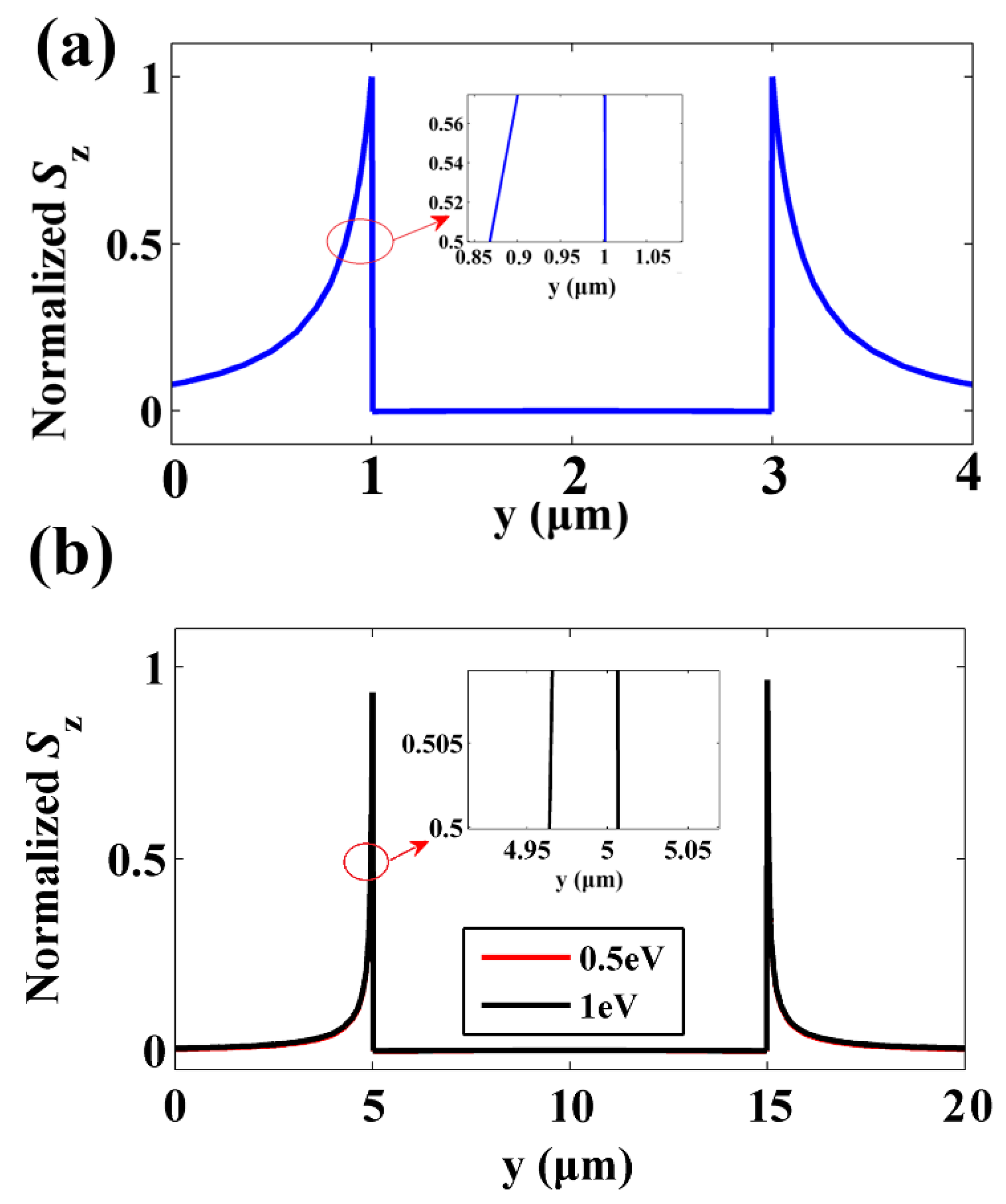
We considered the GCENW waveguide to be surrounded by a dielectric medium (ε2). The elliptical dielectric nanowire (ε1) was covered by monolayer graphene. As shown in Figure 1a, the short axis and long axis were a and b. Here we placed emphasis on the lowest order mode for its long propagation distance. Figure 1b shows the energy distribution of the lowest order GP mode for a = 0.5 μm and b = 1 μm at 3 THz, the majority of the optical energy was restricted in the tips, which is more evident for a larger b/a. The Poynting vector in z direction (Sz) had the largest value at the surface and decayed rapidly away from the interface, seen in Figure 2. Since the elliptical nanowire has two tips, two focal spots with same size could be obtained. Figure 2a, and 2b present the FWHM [51] of Sz at the tips for a = 0.5 μm, b = 1 μm and a = 0.5 μm, b = 5 μm, which were about 140 nm and 40 nm, respectively. Surprisingly, when increasing b/a from 2 to 10, the FWHM of the focal spots reduced from 140 nm to 40 nm, and the propagation length increased from 83 μm to 136 μm. Hence, the ratio of b/a had significant influence on the spot size and propagation length. As shown in Table 1, increasing b/a, the FWHM could be further reduced. However, when b/a increased to a certain value, the elliptical nanowire gradually becomes an approximate parallel plate. Therefore, the ratio of b/a should not be much larger.
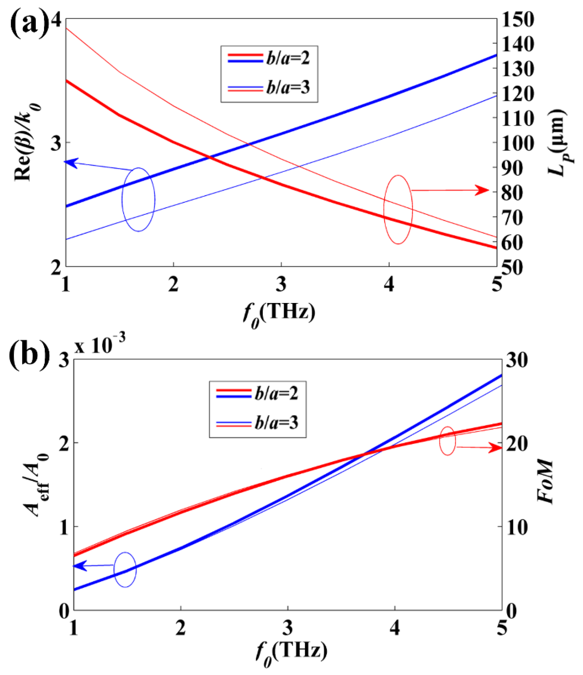
Figure 3a demonstrates the dependencies of the effective mode index and propagation length on frequency for the GP mode. As the frequency ranges from 1 THz to 5 THz, Re(neff) = Re(β)/k0 gradually increased, while the propagation length LP decreased with frequency increasing. At higher frequencies, the much larger absorption of graphene led to the enhancement of the propagation loss. Figure 3b shows the normalized mode area (Aeff/A0), and FoM of the GP mode as a function frequency. When f0 = 1 THz and b/a = 2, LP is approximately 125 μm, and Aeff/A0 is only 2.44 × 10⁻⁴. When b/a = 3, LP is approximately 146 μm, i.e., increased by 16.8%, while the normalized mode area became slightly smaller, seen in Figure 3b. As a result, the GCENW with a larger b/a showed better performance both in propagation length and mode area.
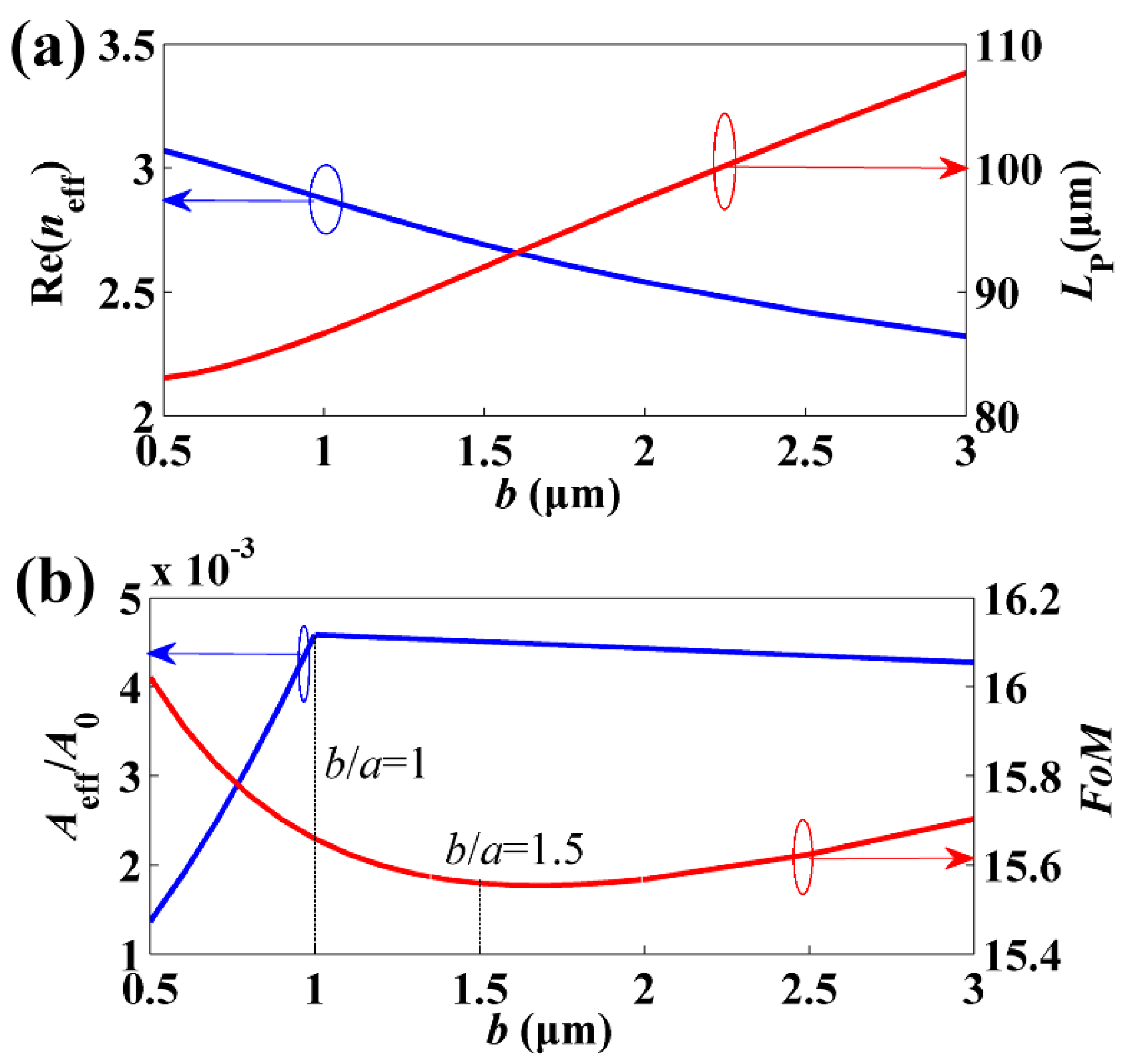
We further discuss the impact of the ratio of b/a on the modal behavior in GCENW. Here, it is necessary to clarify that one can keep a or b constant while changing another. Thus, we set a = 1 μm and swept b from 0.5 μm to 3 μm (i. e., b/a ranging from 0.5 to 3) at 3 THz. Figure 4a depicts Re(neff) and LP with respect to b, and one can see that Re(neff) decreased with the increase of b. For the lowest order mode, propagation length increased with b increasing, and LP is about 83 μm and 107.7 μm for b/a = 0.5 and b/a = 3, respectively. As for the normalized mode area shown in Figure 4b, there was a maximum value at b/a = 1, which is depicted by the vertical black dotted line. This result implies that the graphene-coated circular nanowire (GCCNW) is not the optimal choice. The GP mode in GCENW had superior performances (b/a ranging from 1 to 3) both in propagation length and mode area when compared with the GCCNW (b/a = 1). We will discuss this in Section 4. In addition, the FoM had a minimum value of b/a = 1.5. Therefore, in order to achieve a longer propagation length and smaller mode area, larger b/a values are preferred. The results are in consistent with that of Figure 2.
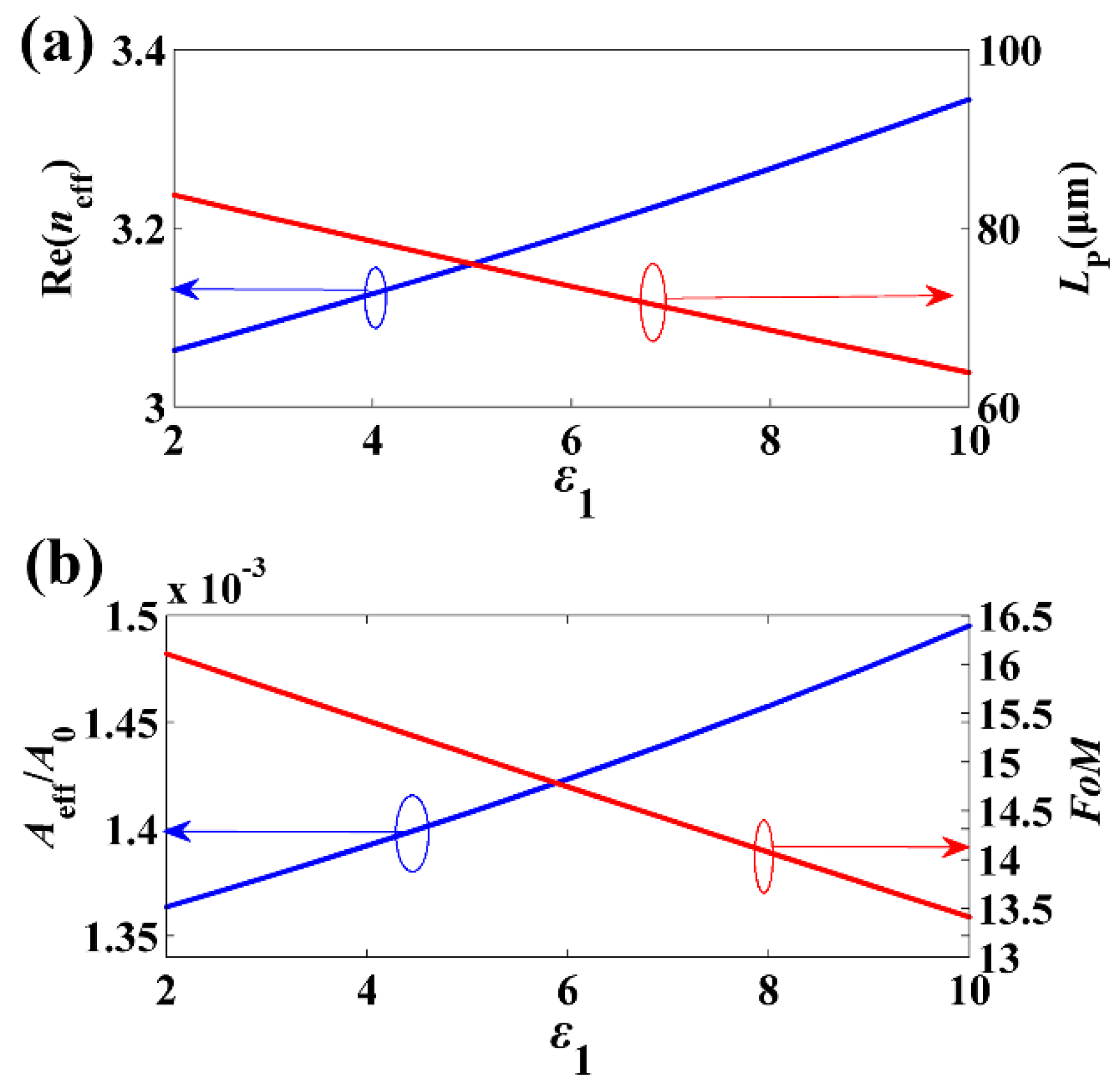
The permittivity of nanowire provided another degree of freedom to be adjusted, which also had a great influence on GP mode in GCENW. Figure 5a shows the relationship between Re(neff), LP and the permittivity at 3 THz. With increasing ε1, Re(neff) almost linearly increased as well as the loss (i.e., decrease of LP). Figure 5b presents Aeff/A0 and FoM with respect to nanowire permittivity. The change of Aeff/A0 with increasing permittivity was very small. For ε1 = 10 and ε1 = 2, the relative error of the normalized mode area was less than 10%. Thus, the permittivity seemed to have a very slight impact on Aeff/A0. Therefore, smaller dielectric permittivity results in better performance of the GP mode.
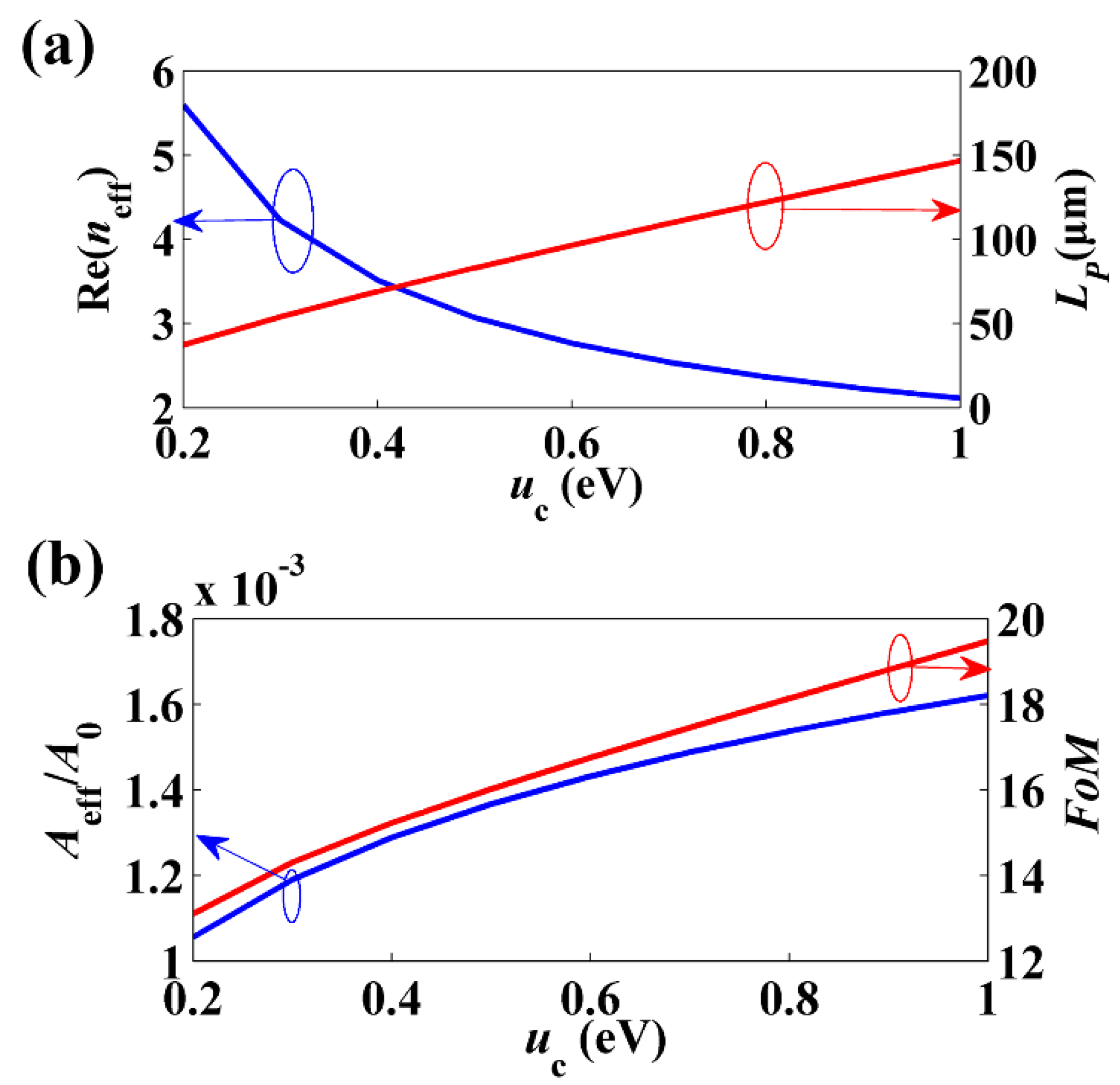
The surface conductivity σg of graphene could be adjusted by changing chemical potential uc. Figure 6 shows the dependences of the GP mode on the chemical potential at f0 = 3 THz. When the chemical potential increased from 0.2 eV to 1 eV, the effective mode index gradually decreased, while LP linearly increased, as depicted in Figure 6a. The normalized mode area was enlarged by less than 2-fold when uc ranging from 0.2 eV to 1 eV, shown in Figure 6b. For b/a = 2 and uc = 1 eV, LP and Aeff/A0 are 147 μm and 1.6 × 10⁻³A0, respectively. When further increasing b/a to 10, the effective mode index of the GP mode was neff = 1.4792 + 0.055868i. The corresponding LP and Aeff/A0 were about 285 μm and 1.4 × 10⁻³.
As shown in Figure 2b, it appeared that when increasing uc from 0.5 eV to 1 eV, the normalized Sz was overlapped with that of uc = 0.5 eV. Thus, the FWHM of the focal spots was still 40 nm. Finally, the increase of uc resulted in the enlargement of FoM. These outcomes imply the possibility of achieving a superior performance of the GCENW by enhancing uc and b/a.

4. Discussion

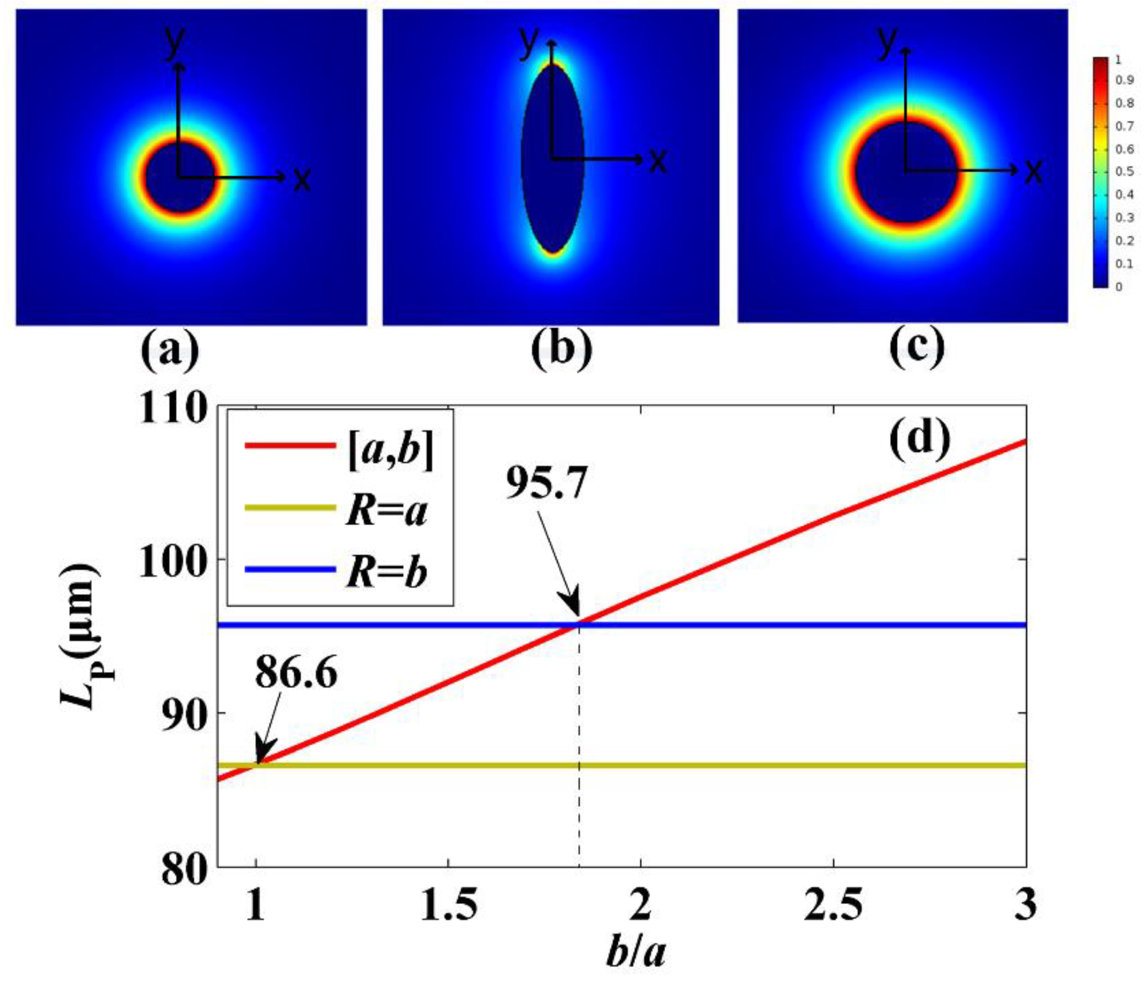
In Figure 4, we studied the dependences of mode properties on the ratio of b/a. Here, we compared the GCENW with two GCCNW waveguides with radii equal to a and b. Figure 7a–c shows the normalized energy distributions of the GP modes for graphene-coated nanowire with R = a = 1 μm, GCENW with a = 1 μm and b = 3 μm, and graphene-coated nanowire with R = b = 3 μm, respectively. In Figure 7d we compared the propagation length of these three GP modes. The red line shows the propagation length of the GP mode in GCENW, with a = 1 μm and b/a ranging from 1 to 3. The gold and blue lines show the propagation length for the plasmon modes of Figure 7a, and 7c, which are LP = 86.6 μm and LP = 95.7 μm, respectively. Therefore, the GP mode in GCENW had a longer propagation length for b/a >1.8 when comparing with GCCNW plasmon modes (with R = 1 μm and R = 3 μm).
Meanwhile, we already knew that the effective mode area of the GP mode was smaller than that of the GCCNW plasmon mode with R = a = 1 μm, seen in Figure 4b. As for the GCCNW plasmon mode with R = b = 3 μm, the effective mode area was about 2.66 × 10⁻² A0, which is enlarged by one order of magnitude when compared with the case of R = a = 1 μm.
Furthermore, we obtained that the FWHM of Sz at the tip was 250 nm for b = 2 μm and a = 1 μm (140 nm for b = 1 μm and a = 0.5 μm, seen in Figure 2a). For GCCNW plasmon mode with R = 1 μm and R = 3 μm, the FWHMs of Sz were approximately 400 nm and 1000 nm, respectively. As the field outside the circular wire was radially polarized, the circular wire shows relatively weak mode confinement. Additionally, the whole graphene layer led to large loss. As for GCENW, the nanofocusing effect of the elliptical nanowire tip resulted in strong modal field confinement, just as the conical metal nanowires. At the same time, only a small fraction of graphene contributed to loss, thus the propagation loss was reduced when compared with circular wire. These results indicated that the plasmon modes in GCCNW were less confined when compared to that of the GCENW, and provided a reasonable explanation for the smaller effective mode area of the GP mode in GCENW.

5. Conclusions

In conclusion, we investigated the subwavelength waveguiding properties of the graphene-coated elliptical nanowires for THz waves. A propagation distance of 285 μm and an effective mode area of 10−3 A0 or smaller were obtained. Results showed that larger b/a, smaller nanowire permittivity, and larger uc could improve the performance of the GCENW. The GP mode in GCENW had superior subwavelength waveguiding performances, both in propagation length and mode area when compared with the corresponding GCCNWs. The introduction of graphene plasmon to guide THz waves far beyond the diffraction limit may have applications in integrated THz photonic devices and THz imaging.

Author Contributions

D.T. and K.W. designed the waveguide structure, and helped proceeding the simulation processes and data analysis; Z.L. organized the paper and contributed in paper writing; Y.Z., G.Z., H.L. and H.W. contributed in paper writing.

Funding

This research was funded partly by the open research Fund of Zhengzhou Normal University, the aid program for Science and Technology Innovative Research Team of Zhengzhou Normal University.

Conflicts of Interest

The authors declare no conflicts of interest.

References

  1. Exter, M.; Fattinger, C.; Grischkowsky, D. Terahertz time-domain spectroscopy of water vapor. Opt. Lett. 1989, 14, 1128–1130. [Google Scholar] [CrossRef] [PubMed]
  2. Hu, B.B.; Nuss, M.C. Imaging with terahertz waves. Opt. Lett. 1995, 20, 1716–1718. [Google Scholar] [CrossRef] [PubMed]
  3. Mittleman, D.M.; Jacobsen, R.H.; Nuss, M.C. T-ray Imaging. IEEE J. Sel. Top. Quantum Electron. 1997, 2, 679–692. [Google Scholar] [CrossRef]
  4. Fitch, M.J.; Osiander, R. Terahertz waves for communications and sensing. Johns Hopkins APL Tech. Dig. 2004, 25, 348–355. [Google Scholar]
  5. Li, S.; Jadidi, M.M.; Murphy, T.E.; Kumar, G. Terahertz surface plasmon polaritons on a semiconductor surface structured with periodic V-grooves. Opt. Express 2013, 21, 7041–7049. [Google Scholar] [CrossRef] [PubMed] [Green Version]
  6. Ung, B.; Mazhorova, A.; Dupuis, A.; Rozé, M.; Skorobogatiy, M. Polymer microstructured optical fibers for terahertz wave guiding. Opt. Express 2011, 19, B848–B861. [Google Scholar] [CrossRef] [PubMed] [Green Version]
  7. Markov, A.; Guerboukha, H.; Skorobogatiy, M. Hybrid metal wire-dielectric terahertz waveguides: Challenges and opportunities [Invited]. J. Opt. Soc. Am. B 2014, 31, 2587. [Google Scholar] [CrossRef]
  8. Atakaramians, S.; Afshar, S.; Monro, T.M.; Abbott, D. Terahertz dielectric waveguides. Adv. Opt. Photonics 2013, 5, 169–215. [Google Scholar] [CrossRef]
  9. Wang, J.; Du, J. Plasmonic and dielectric metasurfaces: Design, fabrication and applications. Appl. Sci. 2016, 6, 239. [Google Scholar] [CrossRef]
  10. Wang, K.; Mittleman, D.M. Metal wires for terahertz wave guiding. Nature 2004, 432, 376–379. [Google Scholar] [CrossRef]
  11. Cao, Q.; Jahns, J. Azimuthally polarized surface plasmons as effective terahertz waveguides. Opt. Express 2005, 13, 511–518. [Google Scholar] [CrossRef] [PubMed]
  12. Xu, L.; Li, F.; Wei, L.; Zhou, J.; Liu, S. Design of surface plasmon nanolaser based on MoS2. Appl. Sci. 2018, 8, 2110. [Google Scholar] [CrossRef]
  13. Heshmat, B.B.; Li, D.; Darcie, T.E.; Gordon, R. Tuning plasmonic resonances of an annular aperture in metal plate. Opt. Express 2011, 19, 5912–5923. [Google Scholar] [CrossRef] [PubMed]
  14. Maier, S.A.; Andrews, S.R.; Martín-Moreno, L.; García-Vidal, F.J. Terahertz surface plasmon-polariton propagation and focusing on periodically corrugated metal wires. Phys. Rev. Lett. 2006, 97, 176805. [Google Scholar] [CrossRef] [PubMed]
  15. Teng, D.; Cao, Q.; Gao, H.; Wang, K.; Zhu, M. Three-wave approximation for the modal field inside high-index dielectric rods of hybrid plasmonic waveguides. J. Mod. Opt. 2016, 63, 1451–1456. [Google Scholar] [CrossRef]
  16. Liang, H.; Ruan, S.; Zhang, M. Terahertz surface wave propagation and focusing on conical metal wires. Opt. Express 2008, 16, 18241. [Google Scholar] [CrossRef]
  17. Zheng, Z.; Kanda, N.; Konishi, K.; Kuwata-Gonokami, M. Efficient coupling of propagating broadband terahertz radial beams to metal wires. Opt. Express 2013, 21, 10642–10650. [Google Scholar] [CrossRef]
  18. Mbonye, M.; Mendis, R.; Mittleman, D.M. A terahertz two-wire waveguide with low bending loss. Appl. Phys. Lett. 2009, 95, 233506. [Google Scholar] [CrossRef] [Green Version]
  19. Pahlevaninezhad, H.; Darcie, T.E.; Heshmat, B. Two-wire waveguide for terahertz. Opt. Express 2010, 18, 7415–7420. [Google Scholar] [CrossRef]
  20. Teng, D.; Cao, Q.; Li, S.; Gao, H. Tapered dual elliptical plasmon waveguides as highly efficient terahertz connectors between approximate plate waveguides and two-wire waveguides. J. Opt. Soc. Am. A 2014, 31, 268–273. [Google Scholar] [CrossRef]
  21. Liang, H.; Ruan, S.; Zhang, M.; Su, H. Nanofocusing of terahertz wave on conical metal wire waveguides. Opt. Commun. 2010, 283, 262–264. [Google Scholar] [CrossRef]
  22. He, X. Investigation of terahertz surface waves of a metallic nanowire. J. Opt. Soc. Am. B 2010, 27, 2298. [Google Scholar] [CrossRef]
  23. Bonaccorso, F.; Sun, Z.; Hasan, T.; Ferrari, A.C. Graphene photonics and optoelectronics. Nat. Photonics 2010, 4, 611. [Google Scholar] [CrossRef]
  24. Politano, A.; Chiarello, G. Plasmon modes in graphene: Status and prospect. Nanoscale 2014, 6, 10927–10940. [Google Scholar] [CrossRef] [PubMed]
  25. Vakil, A.; Engheta, N. Transformation optics using graphene. Science 2011, 332, 1291–1294. [Google Scholar] [CrossRef] [PubMed]
  26. Jablan, M.; Buljan, H.; Soljacic, M. Plasmonics in graphene at infrared frequencies. Phys. Rev. B 2009, 80, 245435. [Google Scholar] [CrossRef] [Green Version]
  27. Wang, B.; Zhang, X.; Garcia-Vidal, F.J.; Yuan, X.; Teng, J. Strong coupling of surface plasmon polaritons in monolayer graphene sheet arrays. Phys. Rev. Lett. 2012, 109, 073901. [Google Scholar] [CrossRef]
  28. Ding, Y.; Guan, X.; Zhu, X.; Hu, H.; Bozhevolnyi, S.I.; Oxenlowe, L.K.; Jin, K.J.; Mortensen, N.A.; Xiao, S. Efficient electro-optic modulation in low-loss graphene-plasmonic slot waveguides. Nanoscale 2017, 9, 15576–15581. [Google Scholar] [CrossRef] [Green Version]
  29. Liu, P.; Zhang, X.; Ma, Z.; Cai, W.; Wang, L.; Xu, J. Surface plasmon modes in graphene wedge and groove waveguides. Opt. Express 2013, 21, 32432–32440. [Google Scholar] [CrossRef]
  30. Lorestaniweiss, Z.; Salar, B. Tunable transverse-electric surface plasmon polariton waves in a parallel-plate graphene-based waveguide. Phys. Scr. 2019. accepted. [Google Scholar] [CrossRef]
  31. Xu, W.; Zhu, Z.; Liu, K.; Zhang, J.; Yuan, X.; Lu, Q.; Qin, S. Dielectric loaded graphene plasmon waveguide. Opt. Express 2015, 23, 5147–5153. [Google Scholar] [CrossRef] [PubMed]
  32. Zhou, X.; Zhang, T.; Chen, L.; Hong, W.; Li, X. A graphene-based hybrid plasmonic waveguide with ultra-deep subwavelength confinement. J. Lightwave Technol. 2014, 32, 3597–3601. [Google Scholar]
  33. Chen, M.; Sheng, P.; Sun, W.; Cai, J. A symmetric terahertz graphene-based hybrid plasmonic waveguide. Opt. Commun. 2016, 376, 41–46. [Google Scholar] [CrossRef]
  34. He, X.; Ning, T.; Lu, S.; Zheng, J.; Li, J.; Li, R.; Pei, L. Ultralow loss graphene-based hybrid plasmonic waveguide with deep-subwavelength confinement. Opt. Express 2018, 26, 10109–10118. [Google Scholar] [CrossRef]
  35. He, X.; Ning, T.; Pei, L.; Zheng, J.; Li, J.; Wen, X.D. Tunable hybridization of graphene plasmons and dielectric modes for highly confined light transmit at terahertz wavelength. Opt. Express 2019, 27, 5961–5972. [Google Scholar] [CrossRef]
  36. Ye, L.; Sui, K.; Liu, Y.; Zhang, M.; Liu, Q. Graphene-based hybrid plasmonic waveguide for highly efficient broadband mid-infrared propagation and modulation. Opt. Express 2018, 26, 15935–15947. [Google Scholar] [CrossRef] [PubMed] [Green Version]
  37. Gao, Y.; Ren, G.; Zhu, B.; Liu, H.; Lian, Y.; Jian, S. Analytical model for plasmon modes in graphene-coated nanowire. Opt. Express 2014, 22, 24322. [Google Scholar] [CrossRef]
  38. Gao, Y.; Shadrivov, I.V. Second harmonic generation in graphene-coated nanowires. Opt. Lett. 2016, 41, 3623–3626. [Google Scholar] [CrossRef]
  39. Hajati, M.; Hajati, Y. High-performance and low-loss plasmon waveguiding in graphene-coated nanowire with substrate. J. Opt. Soc. Am. B 2016, 33, 2560–2565. [Google Scholar] [CrossRef]
  40. Teng, D.; Wang, K.; Li, Z.; Zhao, Y. Graphene-coated nanowire dimers for deep subwavelength waveguiding in mid-infrared range. Opt. Express 2019, 27, 12458–12469. [Google Scholar] [CrossRef]
  41. Davoyan, A.R.; Engheta, N. Salient Features of Deeply Subwavelength Guiding of Terahertz Radiation in Graphene-Coated Fibers. ACS Photonics 2016, 3, 737–742. [Google Scholar] [CrossRef]
  42. Liang, H.; Zhang, L.; Zhang, S.; Cao, T.; Alù, A.; Ruan, S.; Qiu, C.W. Gate-Programmable Electro-Optical Addressing Array of Graphene-Coated Nanowires with Sub-10 nm Resolution. ACS Photonics 2016, 3, 1847–1853. [Google Scholar] [CrossRef]
  43. Kuzmin, D.A.; Bychkov, I.V.; Shavrov, V.G.; Temnov, V.V.; Lee, H.I.; Mok, J. Plasmonically induced magnetic field in graphene-coated nanowires. Opt. Lett. 2016, 41, 396–399. [Google Scholar] [CrossRef] [PubMed]
  44. Huang, Y.; Zhang, L.; Yin, H.; Zhang, M.; Su, H.; Li, I.; Liang, H. Graphene-coated nanowires with a drop-shaped cross section for 10 nm confinement and 1 mm propagation. Opt. Lett. 2017, 42, 2078–2081. [Google Scholar] [CrossRef] [PubMed]
  45. Zhang, T.; Chen, L.; Li, X. Graphene-based tunable broadband hyperlens for far-field subdiffraction imaging at mid-infrared frequencies. Opt. Express 2013, 21, 20888–20899. [Google Scholar] [CrossRef] [PubMed]
  46. Nikitin, A.Y.; Guinea, F.; Garcia-Vidal, F.J.; Martin-Moreno, L. Fields radiated by a nanoemitter in a graphene sheet. Phys. Rev. B 2011, 84, 195446. [Google Scholar] [CrossRef] [Green Version]
  47. Francescato, Y.; Giannini, V.; Maier, S.A. Strongly confined gap plasmon modes in graphene sandwiches and graphene-on-silicon. New J. Phys. 2013, 15, 063020. [Google Scholar] [CrossRef]
  48. Zhou, Y.; Zhu, Y.Y.; Zhang, K.; Wu, H.W.; Peng, R.W.; Fan, R.H.; Wang, M. Plasmonic band structures in doped graphene tubes. Opt. Express 2017, 25, 12081–12089. [Google Scholar] [CrossRef] [PubMed]
  49. Hanson, G.W. Quasi-transverse electromagnetic modes supported by a graphene parallel-plate waveguide. J. Appl. Phys. 2008, 104, 084314. [Google Scholar] [CrossRef]
  50. Xu, J.; Shi, N.; Chen, Y.; Lu, X.; Wei, H.; Lu, Y.; Liu, N.; Zhang, B.; Wang, J. TM01 mode in a cylindrical hybrid plasmonic waveguide with large propagation length. Appl. Opt. 2018, 57, 4043–4047. [Google Scholar] [CrossRef] [PubMed]
  51. Oulton, R.F.; Sorger, V.J.; Pile, D.F.P.; Genov, D.A.; Zhang, X. A hybrid plasmonic waveguide for sub-wavelength confinement and long range propagation. Nat. Photonics 2008, 2, 496–500. [Google Scholar] [CrossRef]
  52. Ghosh, R.R.; Thomas, A.; Bhardwaj, P.; Subramanian, S.; Ahmed, K.; Dhawan, A. Design of long-range hybrid plasmonic waveguides. Opt. Compon. Mater. XVI 2019, 10914, 109141Z. [Google Scholar]
  53. Berini, P. Figures of merit for surface plasmon waveguides. Opt. Express 2006, 14, 13030–13042. [Google Scholar] [CrossRef] [PubMed]
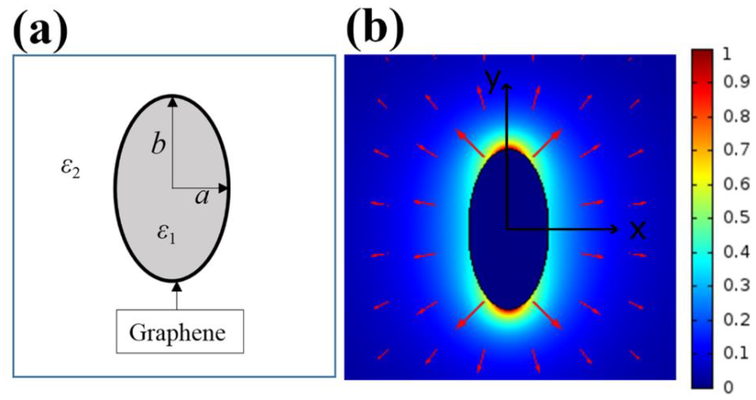
Figure 1. (a) The cross section of the graphene-coated elliptical nanowire (GCENW) waveguide. (b) Normalized electromagnetic energy distribution of the graphene plasmon (GP) mode at 3 THz. Red arrows indicate the polarization directions. The short axis and long axis are a = 0.5 μm and b = 1 μm, respectively. The other parameters are uc = 0.5 eV, ε1 = 2.25, and ε2 = 1.
Applsci 09 02351 g001
Figure 2. The time-averaged Poynting vector Sz along y axis for (a) b/a = 2, uc = 0.5 eV, and (b) b/a = 10, uc = 0.5 eV, 1 eV at 3 THz. The center coordinates of the ellipses are (0, 2 μm) and (0, 10 μm). Here, a = 0.5 μm, ε1 = 2.25, and ε2 = 1. The insets show the enlarged detail of Sz.
Applsci 09 02351 g002
Figure 3. (a) Real part of neff and LP, and (b) Aeff/A0, and figure of merit (FoM) of the GP mode as a function of frequency. Here uc = 0.5 eV, and a = 0.5 μm. The thick and thin lines stand for b/a = 2 and b/a = 3, respectively.
Applsci 09 02351 g003
Figure 4. (a) Real part of neff and LP, and (b) Aeff/A0 and FoM as a function of b at f0 = 3 THz. Here uc = 0.5 eV, ε1 = 2.25, ε2 = 1, and a = 1 μm.
Applsci 09 02351 g004
Figure 5. (a) Real part of neff and LP, and (b) Aeff/A0 and FoM as a function of nanowire permittivity at f0 = 3 THz. Here uc = 0.5 eV, a = 0.5 μm, b = 1 μm, and ε2 = 1.
Applsci 09 02351 g005
Figure 6. (a) Real part of neff and LP, and (b) Aeff/A0 and FoM as a function of chemical potential uc at f0 = 3 THz. Here a = 0.5 μm, b/a = 2, ε1 = 2.25, and ε2 = 1.
Applsci 09 02351 g006
Figure 7. Normalized energy distributions for three GP modes. (a) R = a = 1 μm, (b) a = 1 μm and b = 3 μm, (c) R = b = 3 μm, (d) comparison of the propagation length. The other parameters are uc = 0.5 eV, ε1 = 2.25, ε2 = 1, a = 1 μm, and f0 = 3 THz.
Applsci 09 02351 g007
Table 1. The mode properties versus b/a, and a = 0.5 μm, uc = 0.5 eV, ε1 = 2.25, and ε2 = 1.
b/aneffLP (μm)FWHM (nm)
23.0709 + 0.19168i83140
32.7599 + 0.17064i93100
52.4004 + 0.14512i11075
102.0191 + 0.11677i13640
151.8561 + 0.10439i15236
201.7646 + 0.09751i16332