A Mechatronics-Embedded Pneumatic Soft Modular Robot Powered via Single Air Tube


Abstract
1. Introduction
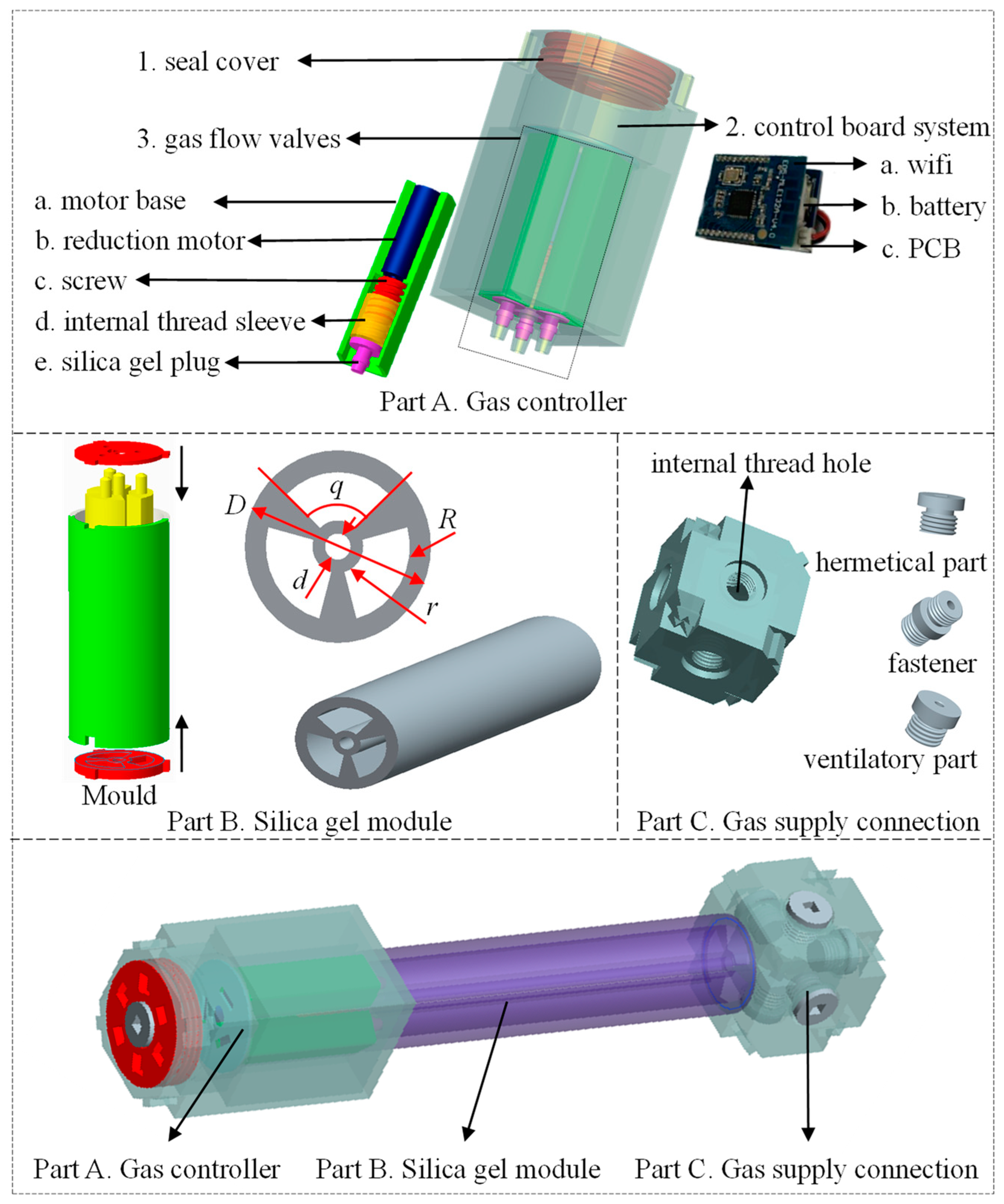
2. Design and Manufacture of Soft Module
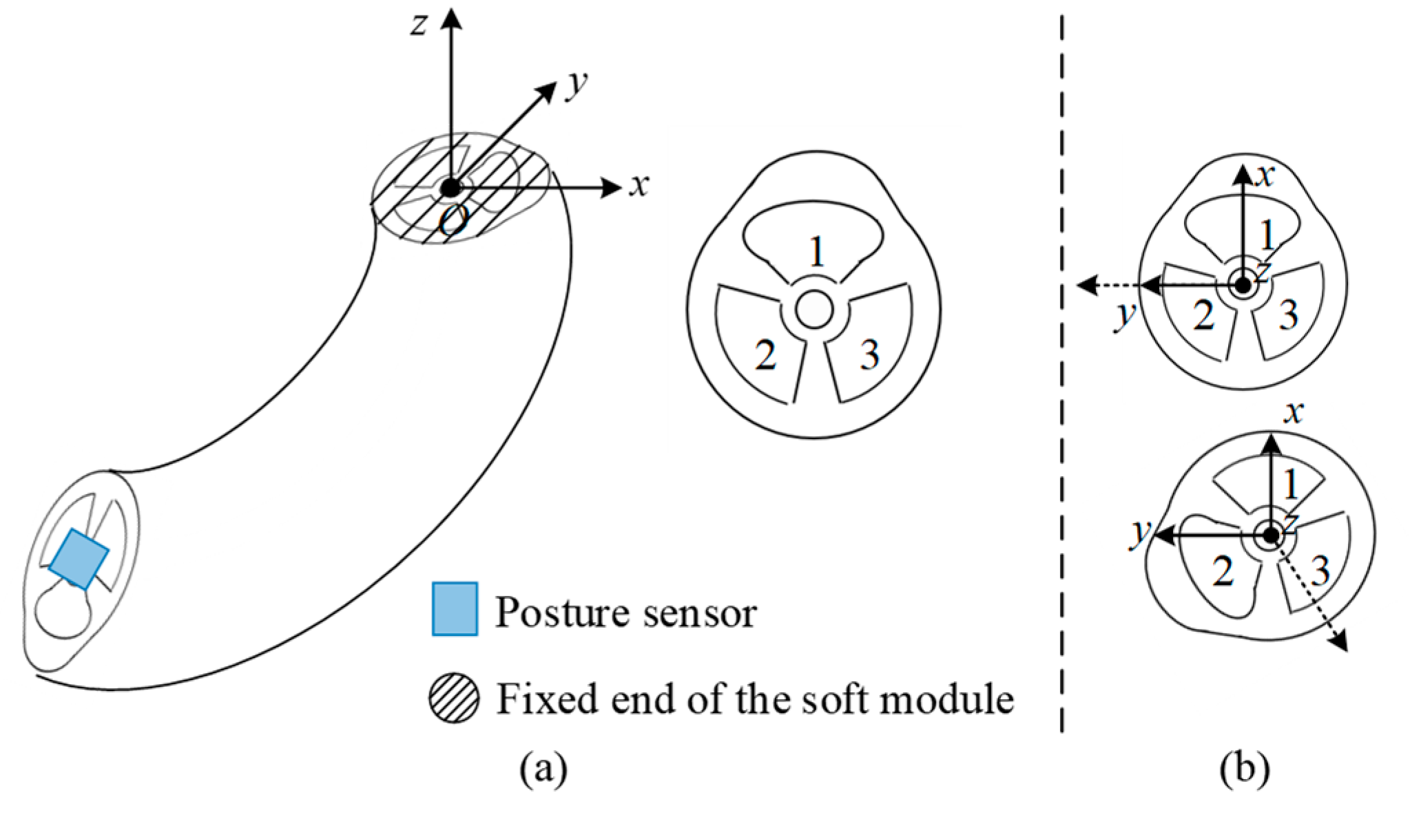
2.1. Structure and Manufacture of Soft Module
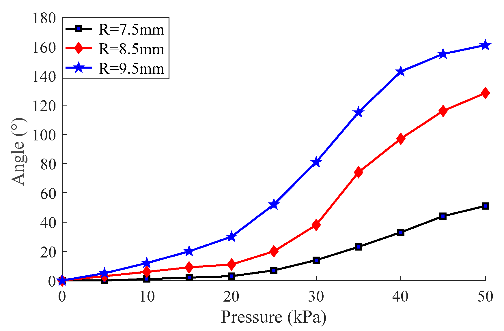
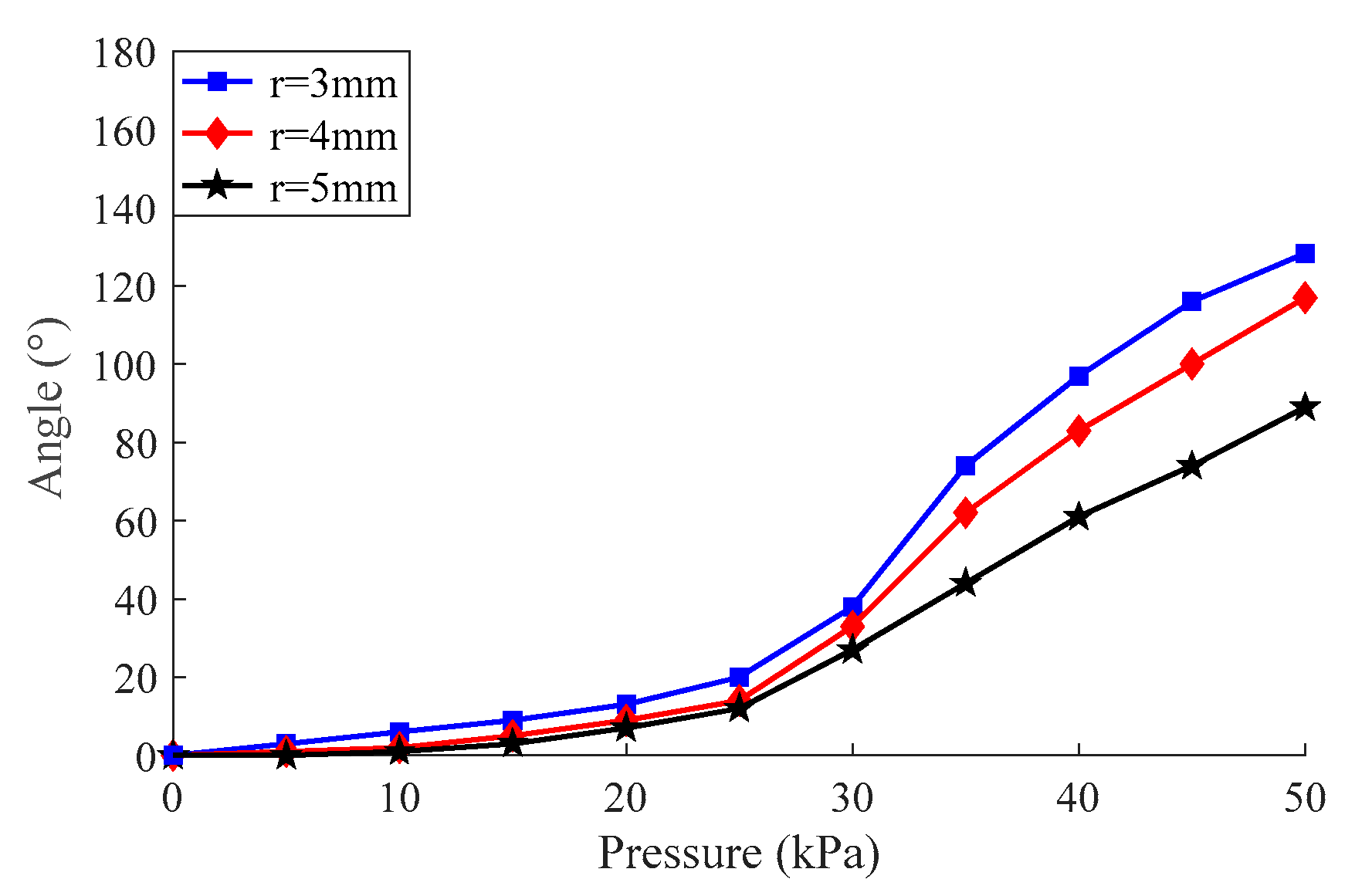
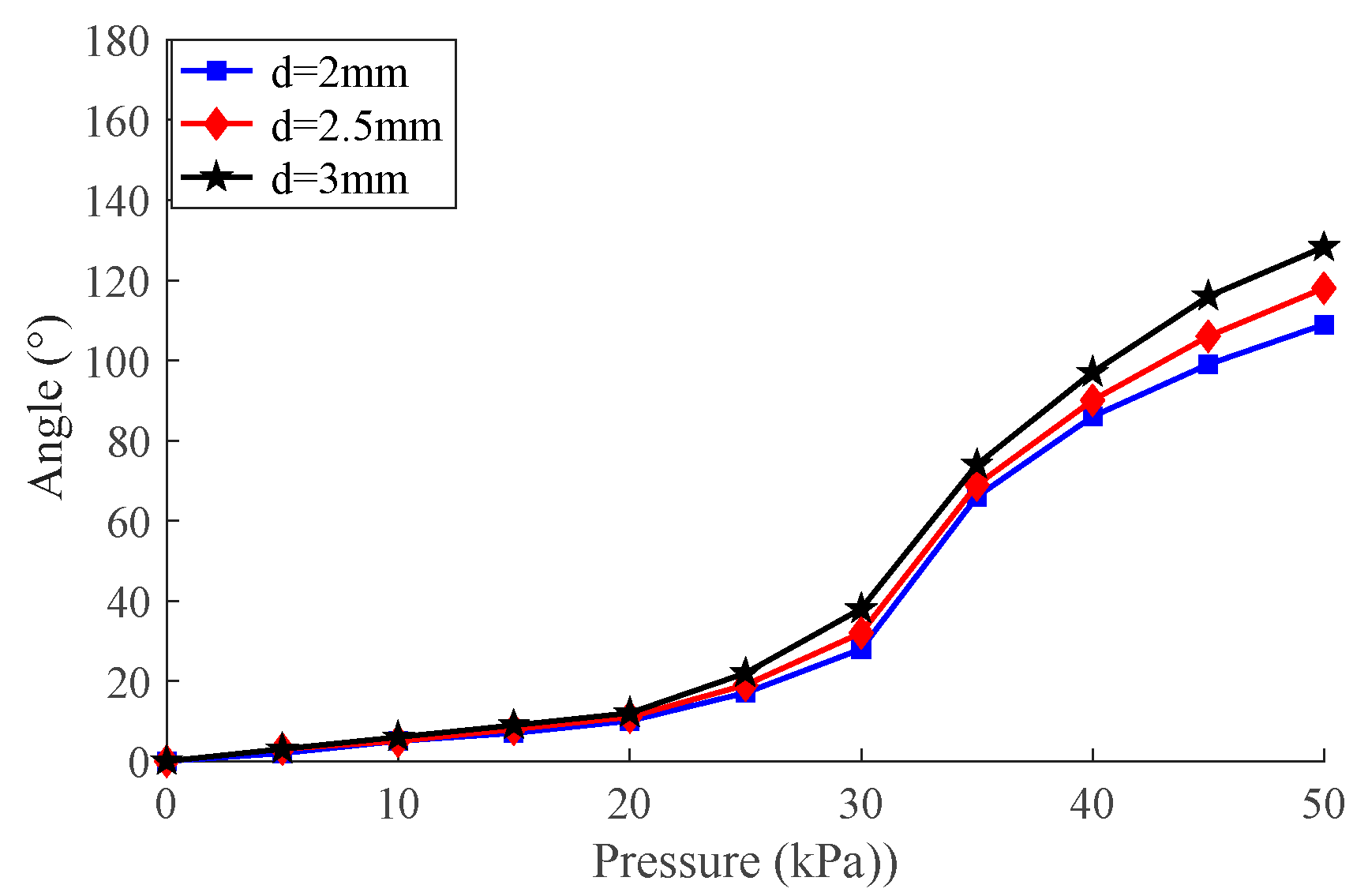
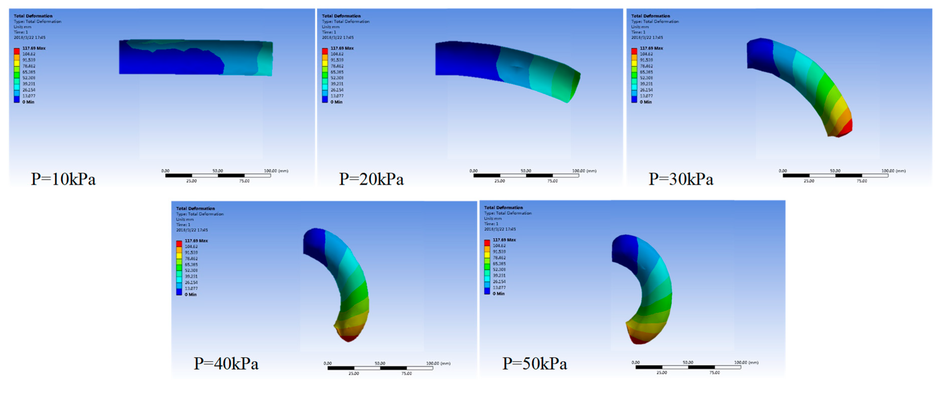
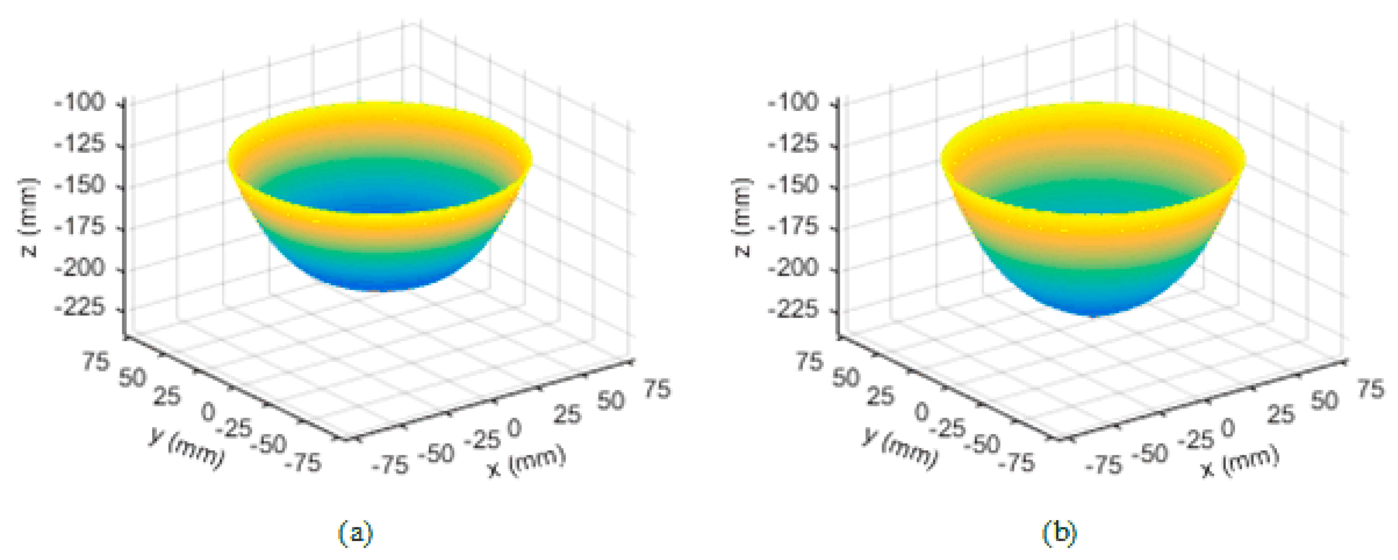
2.2. Parameter Optimization of the Soft Module
3. Control System and Experimental Model
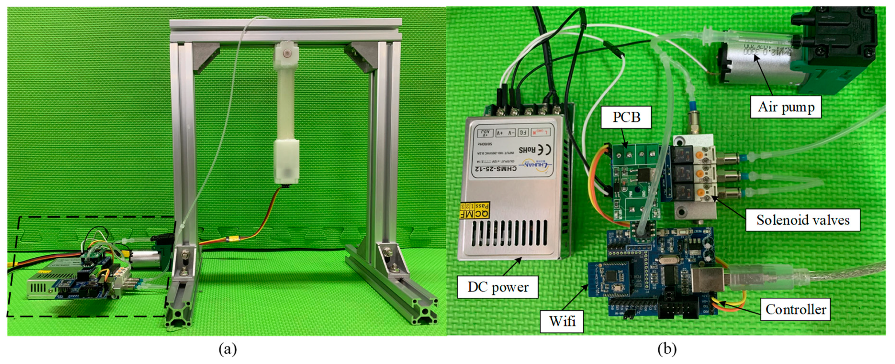
3.1. Control System for the MeSMR
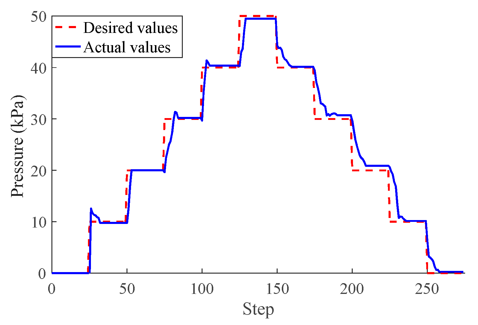
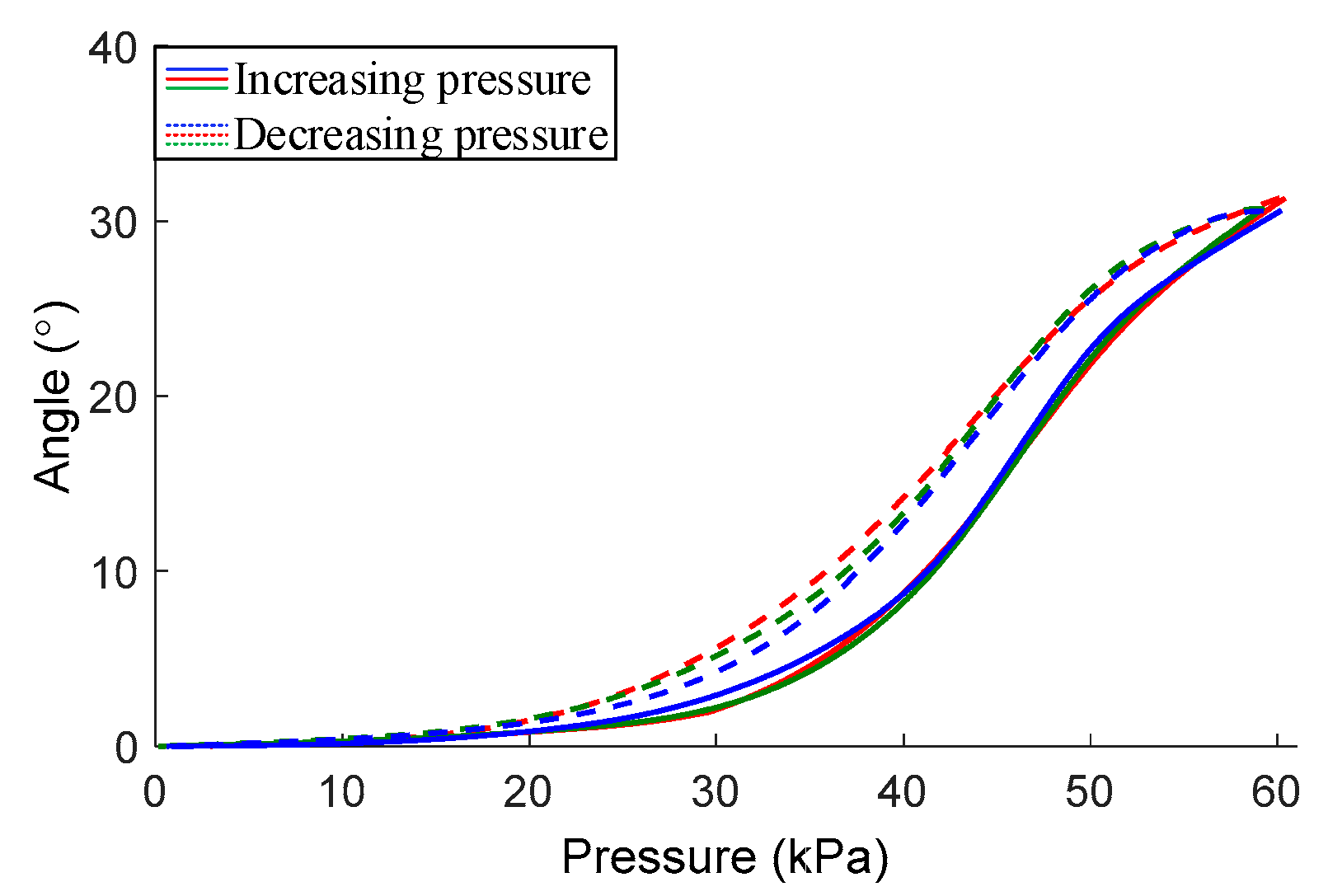
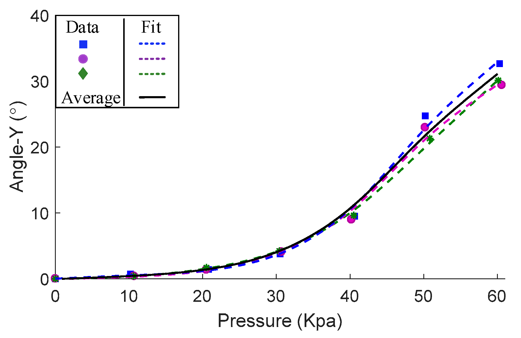
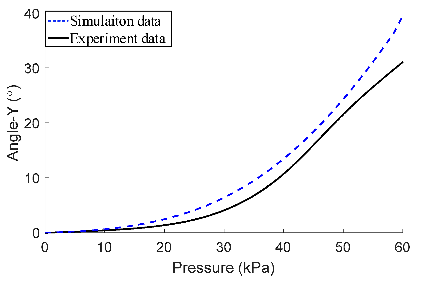
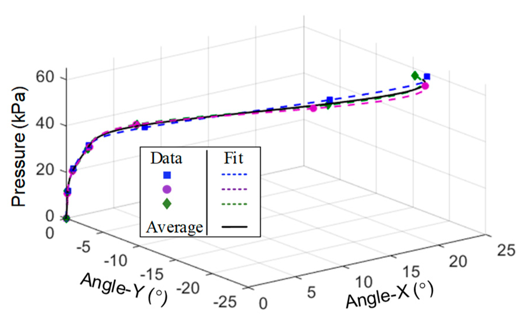
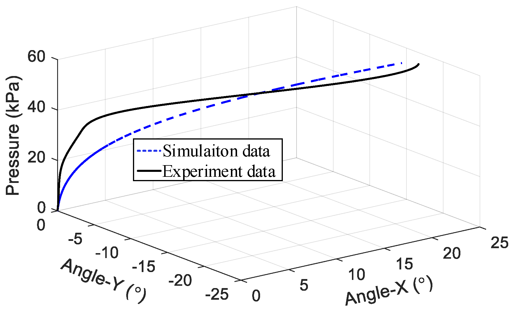
3.2. Experimental Model between Deformation and Pressure of the Module
4. Experiments and Results
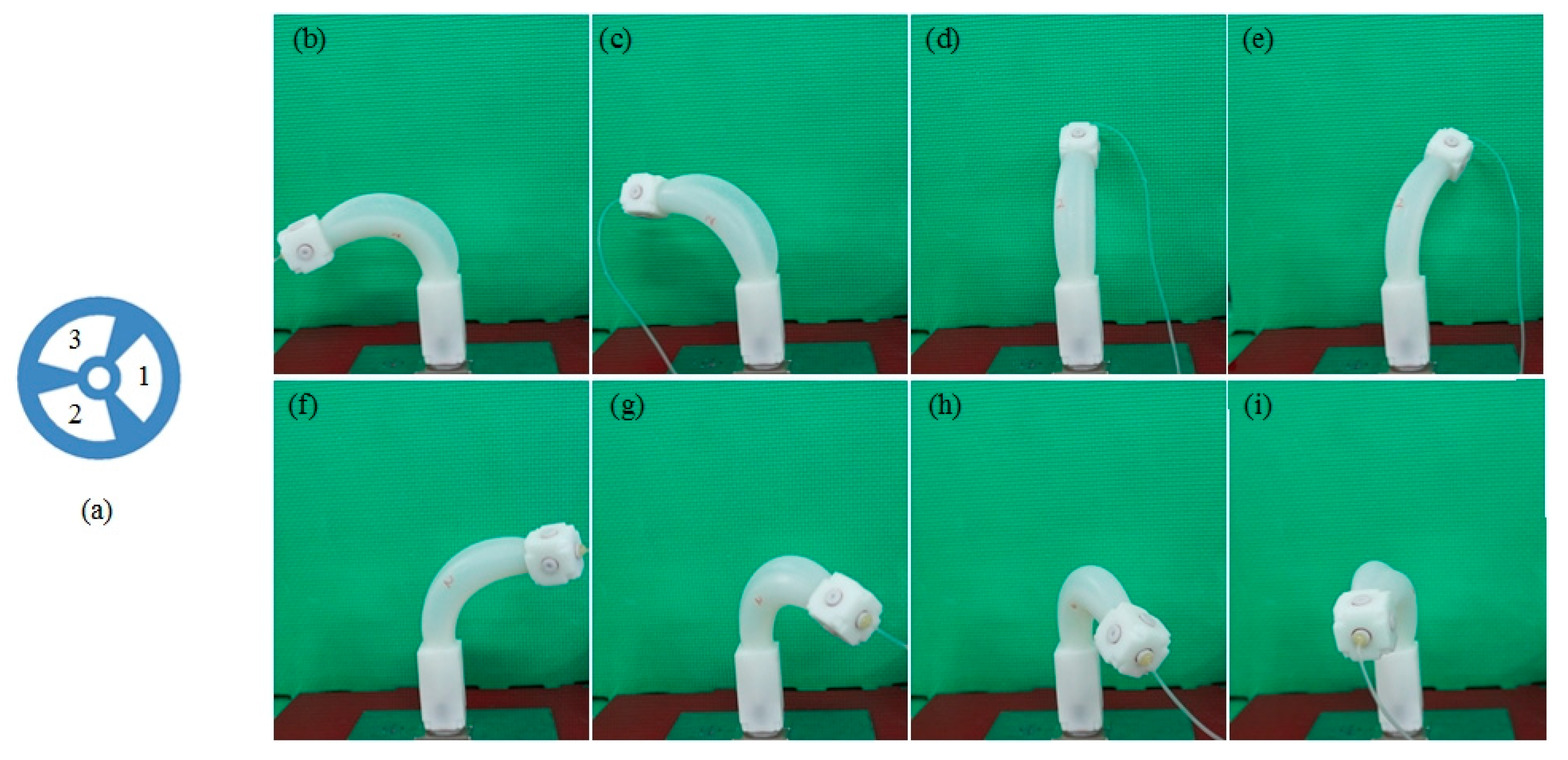
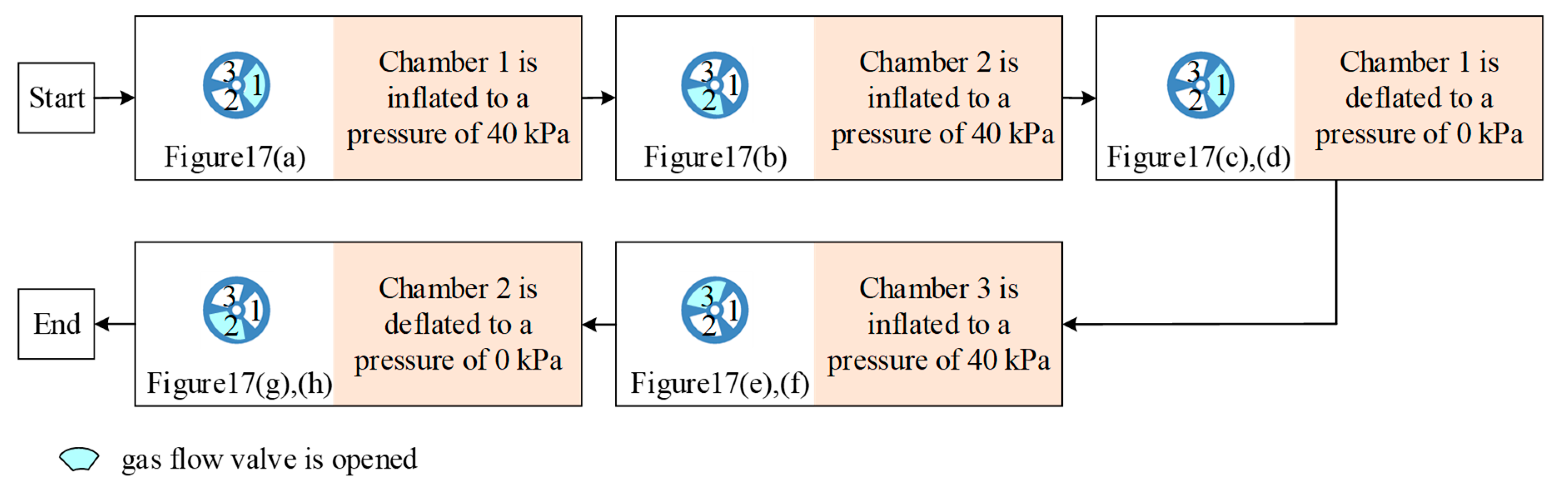
4.1. Bending Motion
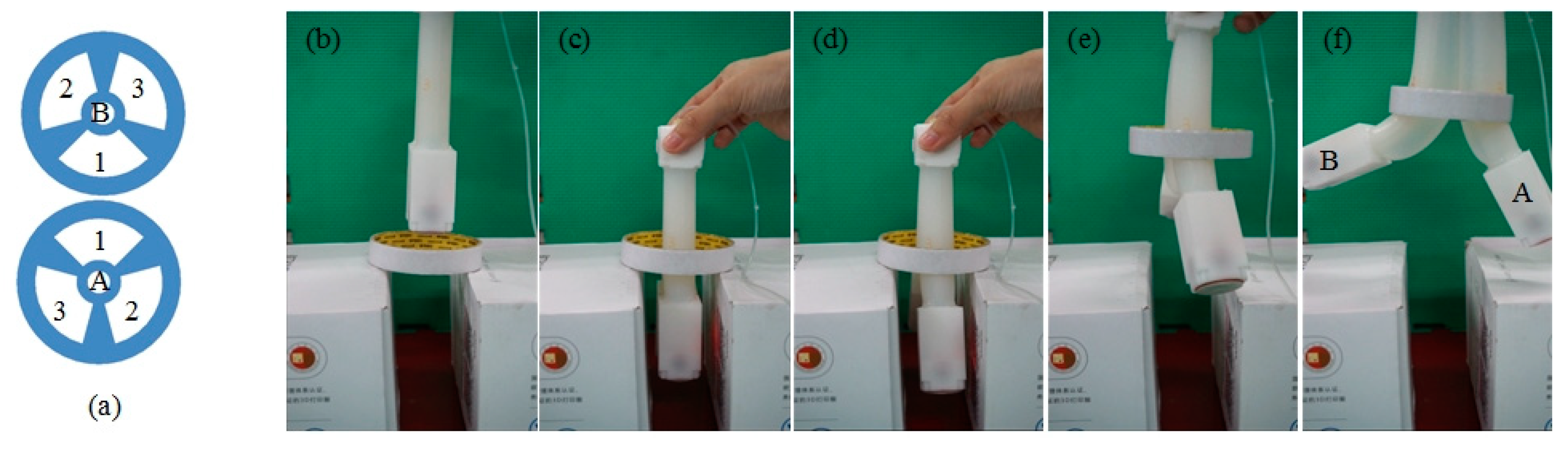
4.2. Hooking Object
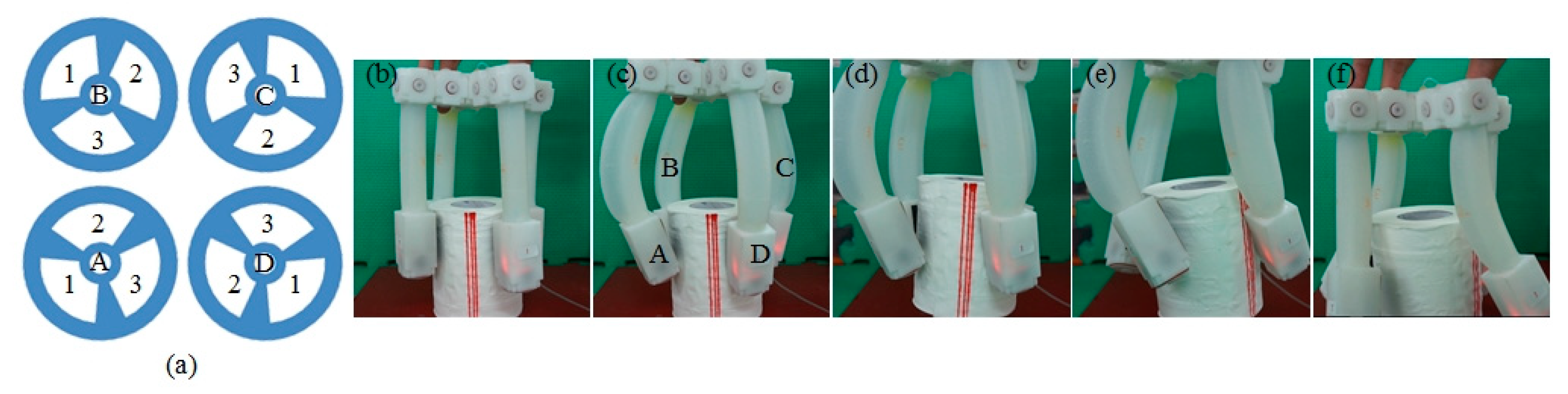
4.3. Twisting Motion
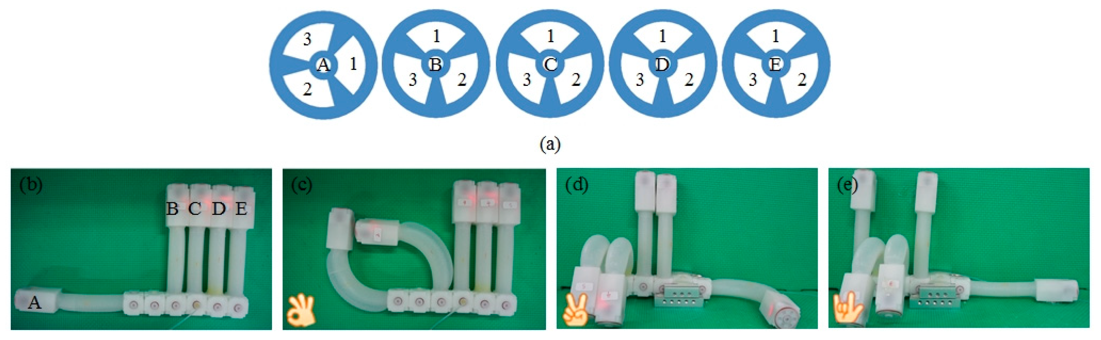
4.4. Bionic gesture
5. Conclusions
Author Contributions
Funding
Conflicts of Interest
References
- Yim, M.; Shen, W.-M.; Salemi, B.; Rus, D.; Moll, M.; Lipson, H.; Klavins, E.; Chirikjian, G.S. Modular self-reconfigurable robot systems—Challenges and opportunities for the future. IEEE Robot. Autom. Mag. 2007, 14, 43–52. [Google Scholar] [CrossRef]
- Zykov, V.; Chan, A.; Lipson, H. Molecubes: An Open-Source Modular Robotics Kit. In Proceedings of the IROS-2007 Workshop on Self-Reconfigurable Robots and Systems and Application, San Diego, CA, USA, 2 November 2007; pp. 3–6. [Google Scholar]
- Moeckel, R.; Jaquier, C.; Drapel, K.; Dittrich, E.; Upegui, A.; Jan Ijspeert, A. Exploring adaptive locomotion with YaMoR, a novel autonomous modular robot with Bluetooth interface. Ind. Robot Int. J. 2006, 33, 285–290. [Google Scholar] [CrossRef]
- Yim, M.; Duff, D.G.; Roufas, K.D. PolyBot: A modular reconfigurable robot. Robotics and Automation. In Proceedings of the IEEE International Conference on Robotics and Automation (ICRA), San Francisco, CA, USA, 24–28 April 2000; pp. 514–520. [Google Scholar]
- Jorgensen, M.W.; Ostergaard, E.H.; Lund, H.H. Modular ATRON: Modules for a Self-Reconfigurable Robot. In Proceedings of the IEEE/RSJ International Conference on Intelligent Robots and Systems (IROS), Sendai, Japan, 28 Stemperber–2 October 2004; pp. 2068–2073. [Google Scholar]
- Castano, A.; Shen, W.M.; Will, P. CONRO: Towards deployable robots with inter-Robots metamorphic capabilities. Auton. Robot 2000, 8, 309–324. [Google Scholar] [CrossRef]
- Kurokawa, H.; Tomita, K.; Kamimura, A.; Kokaji, S.; Hasuo, T.; Murata, S. Distributed self-reconfiguration of M-TRAN III modular robotic system. Int. J. Robot. Res. 2008, 27, 373–385. [Google Scholar] [CrossRef]
- Shen, W.M.; Krivokon, M.; Chiu, H.; Everist, J.; Rubenstein, M.; Venkatesh, J. Multimode lcomotion via SuperBot reconfigurable robots. Auton. Robots 2006, 20, 165–177. [Google Scholar] [CrossRef]
- Zhao, J.; Wang, X.; Jin, H.; Bie, D.; Zhu, Y. Automatic locomotion generation for a UBot modular tobot—Towards both high-speed and multiple patterns. Int. J. Adv. Robot. Syst. 2015, 12, 1–10. [Google Scholar] [CrossRef]
- Wang, X.; Jin, H.; Zhu, Y.; Chen, B.; Bie, D.; Zhang, Y.; Zhao, J. Serpenoid polygonal rolling for chain-type modular robots: A study of modeling, pattern switching and application. Robot. Comput. Integr. Manuf. 2016, 39, 56–67. [Google Scholar] [CrossRef]
- Bie, D.; Gutiérrez-Naranjo, M.A.; Zhao, J.; Zhu, Y. An approach to the bio-inspired control of self-Reconfigurable robots. In Proceedings of the 12th International Conference on Bio-Inspired Computing: Theories an Application (BIC-TA), Harbin, China, 1–3 December 2017; pp. 24–38. [Google Scholar]
- Lipson, H. Challenges and opportunities for design, simulation, and fabrication of Soft robots. Soft Robot. 2014, 1, 21–27. [Google Scholar] [CrossRef]
- Zou, J.; Lin, Y.; Ji, C.; Yang, H. A Reconfigurable Omnidirectional Soft Robot Based on Caterpillar Locomotion. Soft Robot. 2018, 5, 164–174. [Google Scholar] [CrossRef]
- Kurumaya, S.; Phillips, B.T.; Becker, K.P.; Rosen, M.H.; Gruber, D.F.; Galloway, K.C.; Suzumori, K.; Wood, R.J. Modular Soft Robotic Wrist for Underwater Manipulation. Soft Robot. 2018, 5, 399–409. [Google Scholar] [CrossRef]
- Lee, J.Y.; Kim, W.B.; Choi, W.Y.; Cho, K.J. Soft robotic blocks: Introducing SoBL, a fast-build modularized design block. IEEE Robot. Automat. Mag. 2016, 23, 30–41. [Google Scholar] [CrossRef]
- Zhang, Y.; Zheng, T.; Fan, J.; Li, G.; Zhu, Y.; Zhao, J. Nonlinear modeling and docking tests of a soft modular Robot. IEEE Access 2019, 7, 11328–11337. [Google Scholar] [CrossRef]
- Vergara, A.; Lau, Y.S.; Mendoza-Garcia, R.F.; Zagal, J.C. Soft modular robotic cubes: Toward replicating morphogenetic movements of the embryo. PLoS ONE 2017, 12, 1–17. [Google Scholar] [CrossRef] [PubMed]
- Luo, M.; Skorina, E.H.; Tao, W.; Chen, F.; Ozel, S.; Sun, Y.; Onal, C.D. Toward modular soft robotics: Proprioceptive curvature sensing and sliding-mode control of soft bidirectional bending modules. Soft Robot. 2017, 4, 117–125. [Google Scholar] [CrossRef]
- Hamill, S.; Peele, B.; Ferenz, P.; Westwater, M.; Shepherd, R.F.; Kress-Gazit, H. Gait synthesis for modular soft robots. In Proceedings of the International Symposium on Experimental Robotics (ISER), Tokyo, Japan, 3–6 October 2016; pp. 669–678. [Google Scholar]
- Pang, W.; Fei, Y.; He, W. Study on motion process of modular soft robot. In Proceedings of the International Conference on Machine Learning and Cybernetics, Jeju Island, Korea, 10–13 July 2016; pp. 146–151. [Google Scholar]
- Fei, Y.; Gao, H. Nonlinear dynamic modeling on multi-spherical modular soft robots. Nonlinear Dyn. 2014, 78, 831–838. [Google Scholar] [CrossRef]
- Fei, Y.; Wang, X. Study on nonlinear obstacle avoidance on modular soft robots. Nonlinear Dyn. 2015, 82, 91–898. [Google Scholar] [CrossRef]
- Fei, Y.; Pang, W. Analysis on nonlinear turning motion of multi-spherical soft robots. Nonlinear Dyn. 2017, 88, 883–892. [Google Scholar] [CrossRef]
- Luo, M.; Agheli, M.; Onal, C.D. Theoretical modeling and experimental analysis of a pressure-operated soft robotic snake. Soft Robot. 2014, 1, 136–145. [Google Scholar] [CrossRef]
- Nemitz, M.P.; Mihaylov, P.; Barraclough, T.W.; Ross, D.; Stokes, A.A. Using voice coils to actuate modular soft robots: Wormbot, an Example. Soft Robot. 2016, 3, 198–204. [Google Scholar] [CrossRef]
- Umedachi, T.; Trimmer, B.A. Autonomous decentralized control for soft-bodied caterpillar-like modular robot exploiting large and continuum deformation. In Proceedings of the IEEE/RSJ International Conference on Intelligent Robots and Systems (IROS), Daejeon, South Korea, 9–14 October 2016; pp. 292–297. [Google Scholar]
- Agarwal, G.; Robertson, M.A.; Sonar, H.; Paik, J. Design and computational modeling of modular, compliant robot assembly for human lumbar unit and spinal cord. Sci. Rep. 2017, 7, 1–11. [Google Scholar] [CrossRef]
- Robertson, M.A.; Paik, J. New soft robots really suck: Vacuum powered systems empower diverse capabilities. Sci. Robot. 2017, 2, 1–27. [Google Scholar] [CrossRef]


| Stress(MPa) | 0.040 | 0.055 | 0.073 | 0.101 | 0.127 | 0.141 | 0.163 | 0.206 | 0.233 | 0.253 |
| Strain(mm) | 0.078 | 0.294 | 0.509 | 0.734 | 0.968 | 1.082 | 1.207 | 1.431 | 1.676 | 1.874 |
| Gesture | Chambers/Values (kPa) | |||
|---|---|---|---|---|
| OK | A1/45 | B3/45 | B1/30 | —— |
| Yeah | A1/40 | A3/40 | D1/45 | E1/45 |
| Love | C1/45 | D1/45 | —— | —— |
© 2019 by the authors. Licensee MDPI, Basel, Switzerland. This article is an open access article distributed under the terms and conditions of the Creative Commons Attribution (CC BY) license (http://creativecommons.org/licenses/by/4.0/).
Share and Cite
Zhang, Y.; Liu, Y.; Sui, X.; Zheng, T.; Bie, D.; Wang, Y.; Zhao, J.; Zhu, Y. A Mechatronics-Embedded Pneumatic Soft Modular Robot Powered via Single Air Tube. Appl. Sci. 2019, 9, 2260. https://doi.org/10.3390/app9112260
Zhang Y, Liu Y, Sui X, Zheng T, Bie D, Wang Y, Zhao J, Zhu Y. A Mechatronics-Embedded Pneumatic Soft Modular Robot Powered via Single Air Tube. Applied Sciences. 2019; 9(11):2260. https://doi.org/10.3390/app9112260
Chicago/Turabian StyleZhang, Yu, Yubin Liu, Xin Sui, Tianjiao Zheng, Dongyang Bie, Yulin Wang, Jie Zhao, and Yanhe Zhu. 2019. "A Mechatronics-Embedded Pneumatic Soft Modular Robot Powered via Single Air Tube" Applied Sciences 9, no. 11: 2260. https://doi.org/10.3390/app9112260
APA StyleZhang, Y., Liu, Y., Sui, X., Zheng, T., Bie, D., Wang, Y., Zhao, J., & Zhu, Y. (2019). A Mechatronics-Embedded Pneumatic Soft Modular Robot Powered via Single Air Tube. Applied Sciences, 9(11), 2260. https://doi.org/10.3390/app9112260