Abstract
The lower limb exoskeleton is a wearable human–robot interactive equipment, which is tied to human legs and moves synchronously with the human gait. Gait tracking accuracy greatly affects the performance and safety of the lower limb exoskeletons. As the human–robot coupling systems are usually nonlinear and generate unpredictive errors, a conventional iterative controller is regarded as not suitable for safe implementation. Therefore, this study proposed an adaptive control mechanism based on the iterative learning model to track the single leg gait for lower limb exoskeleton control. To assess the performance of the proposed method, this study implemented the real lower limb gait trajectory that was acquired with an optical motion capturing system as the control inputs and assessment benchmark. Then the impact of the human–robot interaction torque on the tracking error was investigated. The results show that the interaction torque has an inevitable impact on the tracking error and the proposed adaptive iterative learning control (AILC) method can effectively reduce such error without sacrificing the iteration efficiency.
1. Introduction
Lower limb exoskeleton robot is a mechanical device to improve a human’s “physical strength” [1,2]. It can assist aged and disabled citizens, rehabilitate injured patients, and extend the capacity of military and engineering forces [3,4,5,6]. As the lower limb exoskeleton should move synchronously with human legs, accurate tracking of human gait is particularly important for its performance [7,8,9]. Human gait is periodic and the gait trajectory tracking can be predicted within finite time intervals. The iterative learning control (ILC) algorithm is such an iterative method to predict gait pattern with prior knowledge [10,11]. ILC takes advantage of the invariant characteristics of a system and improves control performance through historical iterations. Therefore, ILC is suitable for lower limb exoskeleton control with proper gait trajectory tracking. Miao et al. proposed an ILC model to improve the performance of upper limb rehabilitation robotics and concluded that the ILC can be more accurate with repetitive rehabilitation passive training [12]. Wang et al. also designed an ILC algorithm with a forgetting factor to improve the control system robustness at the cost of response speed [13].
Although ILC has been proven effective as a control method for repetitive motions, it is difficult to be applied in practice due to unclear initial value and high tracking error [14,15]. Lin et al. proposed an adaptive fuzzy decoupling control method to approximate the unknown system coefficients and improved the existing ILC model through simplifying the learning process, reducing computing time, and coupling multiple-input multiple output (MIMO) nonlinear systems in real-time operation [16]. Anwar and Juamily implemented adaptive law to smooth exoskeleton interaction and ensure the trajectory-based controller [17]. Other researchers also introduced electromyography (EMG) and other data sources to improve the control accuracy [18,19]. Based on these studies, this study intends to implement an adaptive control mechanism for ILC to minimize the tracking error so that the stability and robustness can be improved in the future. The proposed adaptive iterative learning control (AILC) can not only acquire the prior system knowledge based on multiple iterations but also reduce the nonlinear uncertainty of the controller [20,21].
In summary, this paper contributes to the body of knowledge by introducing a novel adaptive iterative learning control mechanism, which allows a more precise and flexible controller for the lower limb exoskeleton robots. By aggregating and forming a time frame for the prior knowledge, this study utilizes iterative prediction to reduce the gait tracking error so that the nonlinear uncertainty caused by the human–machine coupling can be effectively reduced. The proposed method can further improve the feasibility and safety of the lower limb exoskeleton robots with various functionalities.
The rest of paper is organized as follows: in Section 2, the trajectory tracking algorithm AILC is introduced. Section 3 introduces the design and process of the target trajectory for learning and a validation experiment. In Section 4, the gait tracking results are analyzed and the human–robot interaction moments on gait tracking errors are discussed. In Section 5, the application and limitations of the proposed method are discussed. Section 6 summarizes the conclusions and potential future work.
2. Adaptive Iterative Learning Control
2.1. Design of the AILC Controller
Figure 1 shows the block diagram of a typical iterative learning controller. In the controller, is the desired trajectory and is the initial state. In a given time , the control input should approach and the system output should approach the desired trajectory through iterative parameter updates and learning. is the deviation between the expected output and the actual output . of the iteration is calibrated by the deviation at the closed-loop iteration.

Figure 1.
The block diagram of the iterative learning control (ILC) algorithm.
When the controlled system runs for the time:
where, , , and are the state, output, and input variables of the system, respectively. The tracking error is:
The control law of ILC (iterative learning control) in classical PID (proportion, integral, differential) closed-loop controller can be expressed as:
where, Γ, and are learning gain matrices.
Figure 2 is the schematic diagram of the adaptive iterative learning control (AILC). The adaptive controller corrects the conventional controller’s parameters according to the deviation and a modified value . The iterative learning control system takes the required control system parameters as the function of the running state of the control objective.

Figure 2.
The schematic diagram of the adaptive iterative learning control (AILC).
The control law and adaptive parameter learning the law of the iteration is:
In Equation (4), and are PID gain matrices, is the sign function, which can enhance the anti-interference ability of the system, and is the total number of iterations. In Equation (5), ; is the adaptive parameter; is the transpose of , and:
In Equation (6), , and are the target trajectories of the hip and knee joint of the lower limb exoskeleton, respectively; ; and are the trajectories of the hip and knee joint generated by the iteration.
2.2. Establishment of the Simulation Model
To construct a feasible AILC controller for gait trajectory tracking, a simulation model was built in MATLAB/Simulink (The MathWorks Inc., Natick, MA, USA). The simulation block diagram is shown in Figure 3. The block diagram contains four subroutines as s-function, namely “Input”, “Exoskeleton”, “Controller”, and “Self-adaption”. The “Input” process is used to set the target trajectories of the lower limb exoskeleton. In a validation experiment, the target trajectories were captured by the NDI Optotrak Certus (Northern Digital Inc., Canada), which is as a gait measurement system. The “Exoskeleton” process is used to define the ontology model of lower limb exoskeletons. The “Controller” process contains the control algorithm of the lower limb exoskeleton as shown in Equation (4). The “Self-adaption” process is the adaptive parameter learning module, as shown in Equation (5). In the block diagram, “Phi” is obtained by the adaptive parameter learning process.
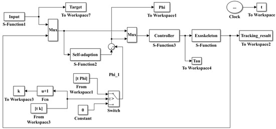
Figure 3.
The simulation block diagram for the AILC-based gait tracking.
3. Validation Experiment
To verify and validate the proposed method, this study conducted an experiment to capture real human gait as the inputs for the simulation and controller. To capture the human subjects’ gaits, a motion capturing system, NDI Optotrak Certus, was used. A motion capture system can be divided into several types, including acoustic type, optical type, electromagnetic type, and inertial type [22,23]. This study used the NDI Optotrak Certus optical 3D motion measurement system. The optical 3D motion capture system has several advantages: (1) it is easy to use and is able to capture a large range of activities without cable and mechanical restrictions; (2) it has a high sampling rate, which can meet the needs of animation, sports, and medical motion measurements; (3) its markers are cheap and convenient to expand. The motion capture system is shown in Figure 4a and it has a precisely calibrated coordinate system and measurement space, as shown in Figure 4b.

Figure 4.
Gait capture system (a) and its coordinate system and measurement space (b).
The position sensor is composed of three CCD (charge coupled device) lenses, which can capture the infrared light emitted by the markers and measure their precise positions. The system control unit (SCU) is a processing device that controls the position sensor and the attached Strobers and streams data to the host computer. Markers are infrared light emitting diodes that are tracked by the position sensor when they are activated by the Strober. The Strober is a device controlled by, and connected to, the SCU, responsible for activating and deactivating markers.
Before the experiment, the physiological data of the subjects, such as gender, quality, height, bone length, and pelvic width were reported. Five markers were attached to the pelvic, hip, knee, ankle, and toe, respectively. Markers were indexed with , as shown in Figure 5 (left). Then, the subjects were allowed to walk around the room for a while to adapt to the test environment. During the experiment, the gait on the flat ground was collected. The angles between the markers were recorded. The scene during the experiment is shown in Figure 5 (right). The data collection time of each trial was 15 s.
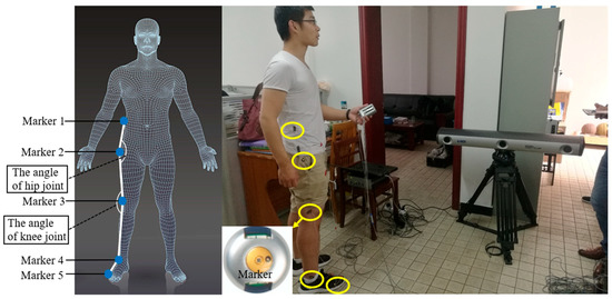
Figure 5.
The layout diagram of markers (left) and gait capture scene (right).
Figure 6 is the flow chart of the experiment, including gait measurement and trajectory tracking modules. The captured gait information was transported into MATLAB/Simulink in real-time for the trajectory tracking simulation.
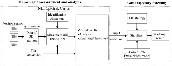
Figure 6.
Flow chart of gait measurement and exoskeleton trajectory tracking.
4. Results and Analysis
The ground truth for the gait prediction was captured by the experiment and the initial values were assumed as the initial angles at time equal to zero. The tracking error was calculated through the experiment process. The initial PID parameters and were set as and the adaptive law parameter was set as 10. After a preliminary test, as the results tend to converge after eight iterations, the results were reported for the first ten iterations, in other words, N was set as 10. Each iteration is composed of a supporting phase (approximately 1.2 s, 60% gait cycle) and a swinging phase (approximately 0.8 s, 40% gait cycle). The tracked angle trajectories of the hip joint and knee joint are shown in Figure 7. The tracked angular velocity of the hip joint and knee joint after 10 iterations is shown in Figure 8. Figure 9 shows the tracking errors of both the angle and angular velocity through all 10 iterations.
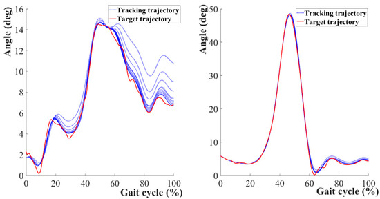
Figure 7.
Gait angle tracking results of the hip (left) and knee (right) joint over 10 iterations.
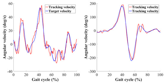
Figure 8.
Gait angular velocity tracking results of the hip (left) and knee (right) joint after 10 iterations.
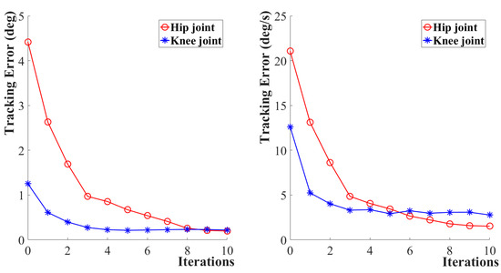
Figure 9.
Tracking errors of angle (left) and angular velocity (right) over 10 iterations.
With Figure 7 and Figure 9 (left), it can be seen that with the proceeding of iterations, the predicated trajectory approached the object trajectory. After 10 iterations, the maximum tracking error of the hip joint was reduced to 0.20 degrees and that of the knee joint was reduced to 0.22 degrees. There was about a 3% relative error of the hip joint angle within 80% of the gait period, while the relative error for the knee joint was about 4.4% over 70% of the gait cycle. With Figure 8 and Figure 9 (right), it can be seen that the angular velocity tracking errors kept decreasing. After 10 iterations, the angular velocity tracking error of the hip joint was 1.52, and that of the knee joint was 2.78. Both maximum errors suggest that the lower extremity exoskeleton robots can be safely operated.
The tracking error inevitably leads to human–robot interaction force/torque, and at the same time, it also is affected by human movement force/torque. To investigate the impact of human–robot interaction torque () on the trajectory tracking error, this study also investigated four forms of human–robot interaction torque , including fixed value, sine change, random change, and sine *random change, as shown in Equation (8). Among them, the function of generates standard normal probability.
Table 1 shows the trajectory tracking errors under different forms of human–robot forces. Figure 10 shows the trajectory tracking errors under four different forms of human–robot interaction torques at the same amplitude. At the same time, the impact of different amplitudes on trajectory tracking under each form of human–robot interaction torque is also demonstrated in Table 1.

Table 1.
The tracking errors with different forms and amplitudes of .

Figure 10.
The impact of on trajectory tracking of the hip joint (left) and the knee (right) joint.
From Figure 10, the majority of torques increases as the tracking error increases. Their amplitudes show that and Therefore, in the case of equal amplitude, the human–robot interaction torque with random change has a smaller error than that with a sine change.
5. Discussion
The lower limb exoskeletons can be divided into three broad categories based on their functionalities. The first category is human performance augmentation exoskeletons for increasing strength, endurance, and other physical capabilities for able-bodied individuals. This type of exoskeleton can be used for lifting heavy objects, carrying heavy loads over large distances, or working with heavy tools. The likely settings for these devices are in warehouses, construction sites, emergency relief operations, or military bases and excursions. The second broad category encompasses assistive devices for individuals with disabilities. Stroke, spinal cord injury, muscle weakness, and other neurological or musculature disorders can lead to difficulty walking or making arm movements. Current estimates suggest that in the United States alone there are 11.7 million individuals who experience difficulty walking and 8.8 million individuals who experience difficulty lifting objects [24]. Assistive robotic exoskeletons can allow users to complete movements they could not complete on their own. For example, many of these exoskeletons are intended to allow an individual with lower limb paralysis to walk with the aid of crutches. The third broad category is therapeutic exoskeletons for rehabilitation. These devices can assist, resist, or perturb the user’s movements to achieve therapeutic exercise. They can train an individual’s muscles and/or nervous system to help them overcome the limitations of a disability when they are not using the exoskeleton. With this proposed study, all types of lower limb exoskeletons can benefit. In the practical application, lower limb exoskeletons have to be applied in complex environmental disturbances and more complex and diversified gaits. It is worthwhile to improve its feasibility by reducing tracking errors and adapting to different working environments and human gaits.
In addition, the proposed method in this study is more suitable for the passive rehabilitation assistance robot as it regards tracking error minimization and safety as a priority. When applied to other purposes, this study is subject to several limitations. First, active lower limb exoskeletons require coordinated movement of both legs. As both legs have complicated interactive movements in non-plane 3D spaces, future work should focus on establishing their trajectory interrelationships. Also, future research should consider the trajectory tracking of the coordinated movement of the legs of the lower limb exoskeleton and optimize trajectory tracking on the basis of different physical environments.
6. Conclusions
This paper proposed an adaptive iterative learning control mechanism to track the gait trajectory of the lower limb exoskeleton. The model was validated with an experimental gait acquisition and results suggest that AILC has better robustness and higher converging speed in dealing with gait trajectory tracking errors. In addition, the impacts of the human–robot interaction torque were studied, and the results show that the human–robot interaction torque can be reduced through minimizing tracking errors. The randomly generated human–robot interaction torque indicates that tracking errors were minimized. The proposed method can broadly impact the industry and be applied for the control of the passive rehabilitation robot and human lower limb assistance equipment.
To summarize the major contribution of this study, the proposed model developed a new control mechanism to reduce the tracking error and nonlinear uncertainty for the human–machine coupling system. It significantly promotes the control accuracy and reliability of the operation of the lower limb exoskeletons. With the help of the proposed method, the safety and feasibility of the lower limb exoskeletons can be improved for practical application.
Author Contributions
Data curation, B.R. and X.L.; formal analysis, B.R. and X.L.; funding acquisition, B.R.; investigation, J.C.; methodology, B.R. and X.L.; project administration, B.R.; writing—original draft, J.C.; writing—review and editing, J.C.
Funding
This research was funded by the National Natural Science Foundation of China (NSFC Grant No. 51775325) and Young Eastern Scholars Program of Shanghai (Grant No. QD2016033).
Conflicts of Interest
The authors declare no conflicts of interest. The funders had no role in the design of the study; in the collection, analyses, or interpretation of data; in the writing of the manuscript, or in the decision to publish the results.
References
- Young, A.J.; Ferris, D.P. State-of-the-art and Future Directions for Robotic Lower Limb Robotic Exoskeletons. IEEE Trans. Neural Syst. Rehabil. Eng. 2017, 25, 171–182. [Google Scholar] [CrossRef] [PubMed]
- Aliman, N.; Ramli, R.; Haris, S.M.M. Design and development of lower limb exoskeletons: A survey. Rob. Auton. Syst. 2017, 95, 102–116. [Google Scholar] [CrossRef]
- Murray, S.A.; Ha, K.H.; Hartigan, C.; Goldfarb, M. An assistive control approach for a lower-limb exoskeleton to facilitate recovery of walking following stroke. IEEE Trans. Neural Syst. Rehabil. Eng. 2015, 23, 441–449. [Google Scholar] [CrossRef] [PubMed]
- Yan, T.; Cempini, M.; Oddo, C.M.; Vitiello, N. Review of assistive strategies in powered lower-limb orthoses and exoskeletons. Rob. Auton. Syst. 2015, 64, 120–136. [Google Scholar] [CrossRef]
- Agrawal, A.; Dube, A.N.; Kansara, D.; Shah, S.; Sheth, S. Exoskeleton: The Friend of Mankind in context of Rehabilitation and Enhancement. Indian J. Sci. Technol. 2016. Available online: http://indjst.org/index.php/indjst/article/viewFile/100889/77458 (accessed on 20 May 2019).
- Yeo, W.-H.; Wei Hong, Y.; King, Y.-J.; Ting, C.-H.; Chuah, Y.-D.; Lee, J.-V.; Chok, E.-T. Lower Extremity Exoskeleton: Review and Challenges Surrounding the Technology and its Role in Rehabilitation of Lower Limbs. Aust. J. Basic Appl. Sci. 2013, 7, 520–524. [Google Scholar]
- Zhang, C.; Liu, G.; Li, C.; Zhao, J.; Yu, H.; Zhu, Y. Development of a lower limb rehabilitation exoskeleton based on real-time gait detection and gait tracking. Adv. Mech. Eng. 2016. [Google Scholar] [CrossRef]
- Wang, L.; Wang, S.; Van Asseldonk, E.H.F.; Van Der Kooij, H. Actively controlled lateral gait assistance in a lower limb exoskeleton. In Proceedings of the IEEE International Conference on Intelligent Robots and Systems, Tokyo, Japan, 3–7 November 2013; pp. 965–970. [Google Scholar]
- Beyl, P.; van Damme, M.; van Ham, R.; Vanderborght, B.; Lefeber, D. Design and control of a lower limb exoskeleton for robot-assisted gait training. Appl. Bionics Biomech. 2009, 6, 229–243. [Google Scholar] [CrossRef]
- Wang, Y.; Gao, F.; Doyle, F.J. Survey on iterative learning control, repetitive control, and run-to-run control. J. Process Control. 2009, 19, 1589–1600. [Google Scholar] [CrossRef]
- Schoellig, A.P.; Mueller, F.L.; D’Andrea, R. Optimization-based iterative learning for precise quadrocopter trajectory tracking. Auton. Robots 2012, 33, 103–127. [Google Scholar] [CrossRef]
- Miao, Q.; Lo, H.S.; Xie, S.Q.; Li, H.S. Iterative Learning Control Method for Improving the Effectiveness of Upper Limb Rehabilitation. In Proceedings of the IEEE International Conference on Mechatronics and Machine Vision in Practice (M2VIP), Nanjing, China, 28–30 November 2016; pp. 1–5. [Google Scholar]
- Wang, F.; Shi, P.; Li, S.; Zhao, S.; Liu, W. Trajectory control of lower limb exoskeleton robot with variable forgetting factor. In Proceedings of the World Congress on Intelligent Control and Automation (WCICA), Guilin, China, 12–15 June 2016; pp. 1502–1507. [Google Scholar]
- Bristow, D.A.; Tharayil, M.; Alleyne, A.G. A survey of iterative learning control. IEEE Control Syst. Mag. 2006, 26, 96–114. [Google Scholar]
- Bristow, D.A.; Barton, K.L.; Alleyne, A.G. Iterative learning control. In The Control Systems Handbook: Control System Advanced Methods, 2nd ed.; Taylor & Francis Group: Boca Raton, FL, USA, 2010. [Google Scholar] [CrossRef]
- Lin, C.W.; Su, S.F.; Chen, M.C. Indirect adaptive fuzzy decoupling control with a lower limb exoskeleton. In Proceedings of the 2016 International Conference on Advanced Robotics and Intelligent Systems (ARIS), Taipei, Taiwan, 31 August–2 September 2016; pp. 1–5. [Google Scholar]
- Anwar, T.; Al Juamily, A. Adaptive trajectory control to achieve smooth interaction force in robotic rehabilitation device. Procedia Comput. Sci. 2014, 42, 160–167. [Google Scholar] [CrossRef]
- Peternel, L.; Noda, T.; Petrič, T.; Ude, A.; Morimoto, J.; Babič, J. Adaptive control of exoskeleton robots for periodic assistive behaviours based on EMG feedback minimisation. PLoS ONE 2016, 11, e0148942. Available online: https://doi.org/10.1371/journal.pone.0148942 (accessed on 17 May 2019). [CrossRef] [PubMed]
- Wang, X.; Li, X.; Wang, J.; Fang, X.; Zhu, X. Data-driven model-free adaptive sliding mode control for the multi degree-of-freedom robotic exoskeleton. Inf. Sci. 2016, 327, 246–257. [Google Scholar] [CrossRef]
- Choi, J.Y.; Lee, J.S. Adaptive iterative learning control of uncertain robotic systems. IEE Proc. Control Theory Appl. 2000, 147, 217–223. [Google Scholar] [CrossRef]
- Jia, X.G.; Yuan, Z.Y. Adaptive iterative learning control for robot manipulators. In Proceedings of the 2010 IEEE International Conference on Intelligent Computing and Intelligent Systems, Xiamen, China, 29–31 October 2010; pp. 139–142. [Google Scholar]
- Pfister, A.; West, A.M.; Bronner, S.; Noah, J.A. Comparative abilities of Microsoft Kinect and Vicon 3D motion capture for gait analysis. J. Med. Eng. Technol. 2014, 38, 274–280. [Google Scholar] [CrossRef] [PubMed]
- Lord, S.; Galna, B.; Rochester, L. Moving forward on gait measurement: Toward a more refined approach. Mov. Disord. 2013, 28, 1534–1543. [Google Scholar] [CrossRef] [PubMed]
- Houtenvill, A.; Brucker, D.; Lauer, E. Annual Compendium of Disability Statistics 2014. Available online: http://disabilitycompendium.org/ (accessed on 26 May 2019).
© 2019 by the authors. Licensee MDPI, Basel, Switzerland. This article is an open access article distributed under the terms and conditions of the Creative Commons Attribution (CC BY) license (http://creativecommons.org/licenses/by/4.0/).