Mode-Selective Photonic Lanterns for Orbital Angular Momentum Mode Division Multiplexing

 , ,
, , 
Abstract
1. Introduction
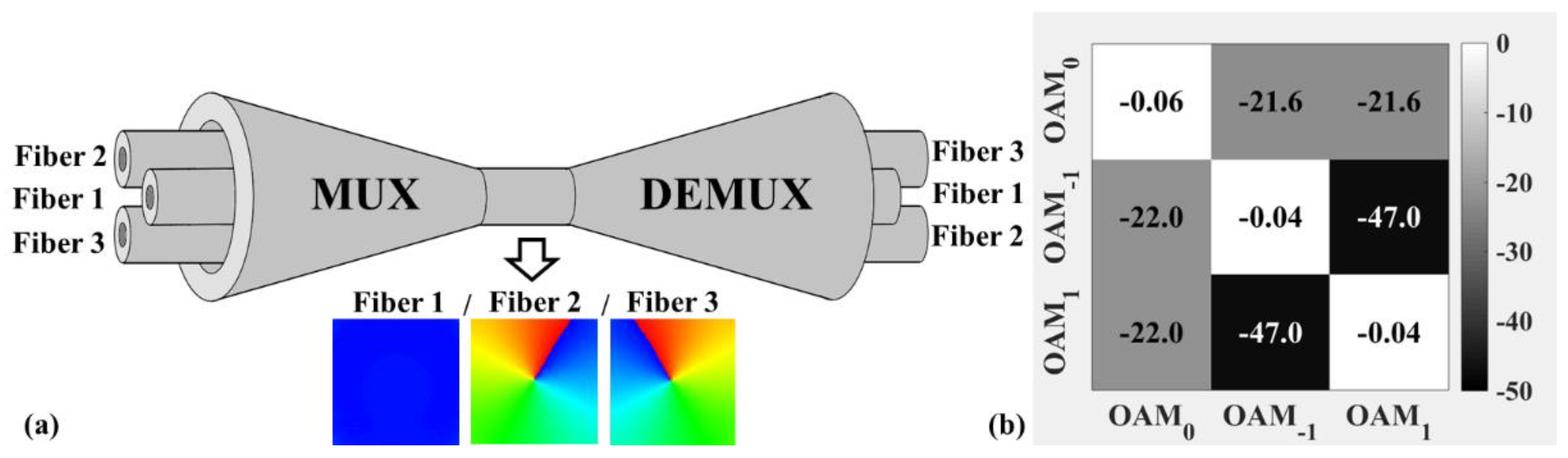
2. Principle
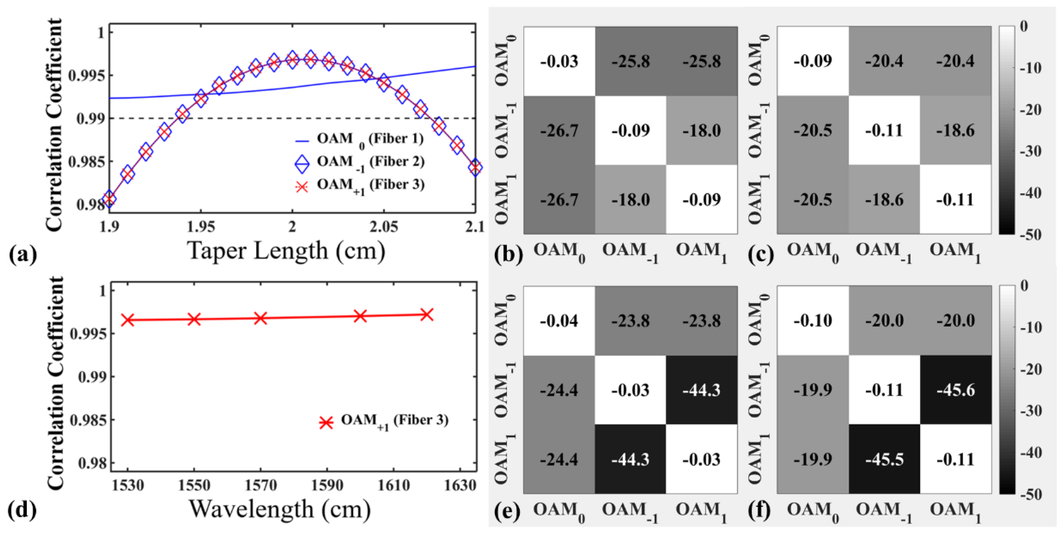
3. Simulation Results
4. Conclusions
Author Contributions
Funding
Conflicts of Interest
References
- Essiambre, R.J.; Kramer, G.; Winzer, P.J.; Foschini, G.J.; Goebel, B. Capacity Limits of Optical Fiber Networks. J. Lightwave Technol. 2010, 28, 662–701. [Google Scholar] [CrossRef]
- Bozinovic, N.; Yue, Y.; Ren, Y.; Tur, M.; Kristensen, P.; Huang, H.; Willner, A.E.; Ramachandran, S. Terabit-scale orbital angular momentum mode division multiplexing in fibers. Science 2013, 340, 1545–1548. [Google Scholar] [CrossRef] [PubMed]
- Gregg, P.; Mirhosseini, M.; Rubano, A.; Marrucci, L.; Karimi, E.; Boyd, R.; Ramachandran, S. Q-plates for Switchable Excitation of Fiber OAM Modes. In Proceedings of the 2015 Conference on Lasers and Electro-Optics (CLEO), San Jose, CA, USA, 10–15 May 2015; pp. 1–2. [Google Scholar]
- Cai, X.; Wang, J.; Strain, M.J.; Johnson-Morris, B.; Zhu, J.; Sorel, M.; O’Brien, J.L.; Thompson, M.G.; Yu, S. Integrated compact optical vortex beam emitters. Science 2012, 338, 363–366. [Google Scholar] [CrossRef] [PubMed]
- Pidishety, S.; Pachava, S.; Gregg, P.; Ramachandran, S.; Brambilla, G.; Srinivasan, B. Orbital angular momentum beam excitation using an all-fiber weakly fused mode selective coupler. Opt. Lett. 2017, 42, 4347–4350. [Google Scholar] [CrossRef] [PubMed]
- Zeng, X.; Li, Y.; Mo, Q.; Tian, Y.; Li, W.; Liu, Z.; Wu, J. Experimental demonstration of Compact and Robust All-Fiber Orbital Angular Momentum Generator. In Proceedings of the 2016 European Conference on Optical Communication (ECOC), Dusseldorf, Germany, 18–22 September 2016; pp. 1–3. [Google Scholar]
- Li, S.; Mo, Q.; Hu, X.; Du, C.; Wang, J. Controllable all-fiber orbital angular momentum mode converter. Opt. Lett. 2015, 40, 4376–4379. [Google Scholar] [CrossRef] [PubMed]
- Pidishety, S.; Khudus, M.A.; Gregg, P.; Ramachandran, S.; Srinivasan, B.; Brambilla, G. OAM Beam Generation using All-fiber Fused Couplers. In Proceedings of the 2016 Conference on Lasers and Electro-Optics (CLEO), San Jose, CA, USA, 5–10 June 2016; pp. 1–2. [Google Scholar]
- Leon-Saval, S.G.; Fontaine, N.K.; Salazar-Gil, J.R.; Ercan, B.; Ryf, R.; Bland-Hawthorn, J. Mode-selective photonic lanterns for space-division multiplexing. Opt. Express 2014, 22, 1036–1044. [Google Scholar] [CrossRef] [PubMed]
- Alvarado-Zacarias, J.C.; Huang, B.; Eznaveh, Z.S.; Fontaine, N.K.; Chen, H.; Ryf, R.; Antonio-Lopez, J.E.; Correa, R.A. Experimental analysis of the modal evolution in photonic lanterns. In Proceedings of the 2017 Optical Fiber Communications Conference and Exhibition (OFC), Los Angeles, CA, USA, 19–23 March 2017; pp. 1–3. [Google Scholar]
- Eznaveh, Z.S.; Zacarias, J.C.; Lopez, J.E.; Shi, K.; Milione, G.; Jung, Y.; Thomsen, B.C.; Richardson, D.J.; Fontaine, N.; Leon-Saval, S.G.; et al. Photonic lantern broadband orbital angular momentum mode multiplexer. Opt. Express 2018, 26, 30042–30051. [Google Scholar] [CrossRef] [PubMed]
- Zeng, X.; Li, Y.; Feng, L.; Wu, S.; Yang, C.; Li, W.; Tong, W.; Wu, J. All-Fiber OAM Mode Multiplexer Employing Photonic Lantern and Mode-Polarization Controller. In Proceedings of the 2018 European Conference on Optical Communication (ECOC), Rome, Italy, 23–27 September 2018; pp. 1–3. [Google Scholar]
- Leon-Saval, S.G.; Birks, T.A.; Bland-Hawthorn, J.; Englund, M. Multimode fiber devices with single-mode performance. Opt. Lett. 2005, 30, 2545–2547. [Google Scholar] [CrossRef] [PubMed]
- Fontaine, N.K.; Ryf, R.; Bland-Hawthorn, J.; Leon-Saval, S.G. Geometric requirements for photonic lanterns in space division multiplexing. Opt. Express 2012, 20, 27123–27132. [Google Scholar] [CrossRef] [PubMed]
- Yeirolatsitis, S.; Harrington, K.; Thomson, R.R.; Birks, T.A. Mode-selective photonic lanterns from multicore fibres. In Proceedings of the 2017 Optical Fiber Communications Conference and Exhibition (OFC), Los Angeles, CA, USA, 19–23 March 2017; pp. 1–3. [Google Scholar]
- Shen, L.; Gan, L.; Huo, L.; Yang, C.; Tong, W.; Fu, S.; Tang, M.; Liu, D. Design of highly mode group selective photonic lanterns with geometric optimization. Appl. Opt. 2018, 57, 7065–7069. [Google Scholar] [CrossRef] [PubMed]
- Ramachandran, S.; Fini, J.M.; Mermelstein, M.; Nicholson, J.W.; Ghalmi, S.; Yan, M.F. Ultra-large effective-area, higher-order mode fibers: A new strategy for high-power lasers. Laser Photonics Rev. 2008, 2, 429–448. [Google Scholar] [CrossRef]
- Sai, X.; Li, Y.; Yang, C.; Li, W.; Qiu, J.; Hong, X.; Zuo, Y.; Guo, H.; Tong, W.; Wu, J. Design of elliptical-core mode-selective photonic lanterns with six modes for MIMO-free mode division multiplexing systems. Opt. Lett. 2017, 42, 4355–4358. [Google Scholar] [PubMed]


© 2019 by the authors. Licensee MDPI, Basel, Switzerland. This article is an open access article distributed under the terms and conditions of the Creative Commons Attribution (CC BY) license (http://creativecommons.org/licenses/by/4.0/).
Share and Cite
Li, Y.; Li, Y.; Feng, L.; Yang, C.; Li, W.; Qiu, J.; Hong, X.; Zuo, Y.; Guo, H.; Tong, W.; et al. Mode-Selective Photonic Lanterns for Orbital Angular Momentum Mode Division Multiplexing. Appl. Sci. 2019, 9, 2233. https://doi.org/10.3390/app9112233
Li Y, Li Y, Feng L, Yang C, Li W, Qiu J, Hong X, Zuo Y, Guo H, Tong W, et al. Mode-Selective Photonic Lanterns for Orbital Angular Momentum Mode Division Multiplexing. Applied Sciences. 2019; 9(11):2233. https://doi.org/10.3390/app9112233
Chicago/Turabian StyleLi, Yan, Yang Li, Lipeng Feng, Chen Yang, Wei Li, Jifang Qiu, Xiaobin Hong, Yong Zuo, Hongxiang Guo, Weijun Tong, and et al. 2019. "Mode-Selective Photonic Lanterns for Orbital Angular Momentum Mode Division Multiplexing" Applied Sciences 9, no. 11: 2233. https://doi.org/10.3390/app9112233
APA StyleLi, Y., Li, Y., Feng, L., Yang, C., Li, W., Qiu, J., Hong, X., Zuo, Y., Guo, H., Tong, W., & Wu, J. (2019). Mode-Selective Photonic Lanterns for Orbital Angular Momentum Mode Division Multiplexing. Applied Sciences, 9(11), 2233. https://doi.org/10.3390/app9112233