Abstract
It is well-known that many species of owl have the unique ability to fly silently, which can be attributed to their distinctive and special feather adaptations. Inspired by the owls, researchers attempted to reduce the aerodynamic noise of aircraft and other structures by learning their noise reduction features from different viewpoints and then using the gained knowledge to develop a number of innovative noise reduction solutions. Although fruitful results have been achieved in the bio-inspired aerodynamic noise control, as far as the authors know, comparatively little work has been done to summarize the main findings and progresses in this area. In this bibliographic survey, we systematically review the progresses and trends of the bio-inspired aerodynamic noise control, including the macroscopic and microscopic morphological characteristics of the owl wing feathers, the noise measurements on both flying birds in the field and prepared wings in the wind tunnel, as well as theoretical, numerical and experimental studies that explored the feasibility, parameter influence, aerodynamic effects and underlying mechanisms of the four main bio-inspired noise reduction techniques, i.e., leading edge serrations, trailing edge serrations, fringe-type trailing edge extensions and porous material inspired noise reduction. Finally, we also give some suggestions for future work.
1. Introduction
In recent years, the problem of aerodynamic noise and its control have become a matter of serious concern and thus attracted a number of researchers’ interest. With the rapid development of the aviation industry and the ever-increasing popularity of air travel, the number of large commercial aircraft, as well as expanded and newly built airports, has increased dramatically. The problem of aircraft noise control has attracted more and more attention, and more stringent standards have been set by the International Civil Aviation Organization (ICAO) on aircraft movements during take-off and landing approach phases. Therefore, NASA, Boeing and so on regard the reduction of noise emission of the aircraft itself aerodynamically as the basic requirement for modern aircraft design and are devoted to the development of silent aircraft [1,2,3,4,5]. As an environmentally acceptable and technologically mature renewable energy, wind energy has been gradually utilized by human beings. However, with the rapid growth of the total installed capacity of the global wind power, large-scale wind farms and wind turbines with increased rotor diameter will inevitably get closer to the densely populated residential areas. As a result, the accompanying noise pollution problems lead to more complaints from the surrounding residents [6,7]. At present, the speed of trains has reached more than 200 km per hour. High-speed trains at 350 km per hour or even faster speed are also being planned. Therefore, to restrain the increase of wayside noise along railway lines is a key issue that cannot be avoided since the acoustic power of the radiated aerodynamic noise satisfies a sixth-order velocity dependence [8].
In the past few decades, a number of methods and devices have been investigated with the aim to reduce the aerodynamic noise, which can be classified into active and passive techniques [9]. Active control techniques need some energy input or relevant auxiliary equipment to manipulate the flow around the objects, such as wall-normal suction or blowing [10,11,12,13] and plasma actuator [14]. On the other hand, passive techniques can control noise emission by making small geometry changes or adding other materials to the surface of the objects, such as vortex generator [15]. However, the advancement of current low noise technologies has gradually entered the bottleneck period and appears to be insufficient to achieve the target of “A Vision for 2020” to reduce the perceived noise to 50% of the noise level in 2000 by 2020 [16], not to mention an even greater challenging objective of “Flightpath 2050” to reduce the Effective Perceived Noise (EPN) levels by 65% in 2050 [17]. Therefore, there is an urgent need to introduce innovative ideas and the engineering of new technologies. Among them, bio-inspired aerodynamic noise control is one of the most promising techniques.
Bionics investigates the structure, function and working principles of biological systems, and tries to transplant these concepts found in nature to create new engineering technologies, and to invent superior instruments, devices, and machines to help solving complex human problems [18]. In the past few decades, bionics has achieved a lot of research results. For example, the bullet-shaped front of the high-speed trains, inspired by the streamlined long-tailed beak of the kingfisher, can reduce the energy consumption of trains and solve the “sonic explosion” problem that occurs when trains pass through narrow tunnels [19]. Swimsuits made in the style of sharkskin can reduce the resistance of the water when athletes are swimming.
The invention of the aircraft was inspired by bird flight and bird wings more than 100 years ago. Recent observations and studies on most genera of owls found that they can fly quietly close to their prey, and have the well-known ability of silent flight, which may be an excellent biological clue for finding solutions for quieter aircraft and other aerodynamic structures. Graham [20] compared the wing feathers of the owls and other non-silent flying birds, and suggested that the owl’s wings have three distinctive and unique characteristics that can reduce noise (see Figure 1), namely, the serrated feathers on the leading edges, the fringes formed at the trailing edges, and the soft downy coating on the surface of wings and legs. In his opinion, it is these characteristics that make the owls “silent flight”. Inspired by owls, researchers attempted to reduce aerodynamic noise by learning their noise reduction features from different viewpoints and developed a number of innovative noise reduction solutions, including serration-type noise reduction, fringe-type noise reduction, and porous material inspired noise reduction.
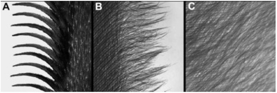
Figure 1.
Details of the three special feather adaptations of the barn owl (redrawn from [21]): (A) leading edge serrations; (B) trailing edge fringes; and (C) soft downy coating surface.
Research into the bio-inspired aerodynamic noise control has continued for more than sixty years. The first boom seems to appear in the 1970s, while the second one is in the past twenty years (see Figure 2). This prolonged period of effort has achieved many fruitful results on the macroscopic and microscopic morphological characteristics of the owl wing feathers, as well as on the noise measurements of flying birds in the field or prepared wings in the wind tunnel. Meanwhile, several theoretical, numerical and experimental studies have been carried out in the past to explore the feasibility, parameter influence, aerodynamic effects and underlying mechanisms of the serration-type, fringe-type and porous material inspired noise reduction techniques. However, as far as the authors know, comparatively little work has been done to summarize the main findings and progresses in these areas. This motivates the present paper, which aims to go one step into that direction. In this bibliographic survey, the progresses and trends of the bio-inspired aerodynamic noise control are systematically reviewed, and some suggestions for future work are also discussed, in an effort to advance the state of the art in these important areas and try to focus future studies into the most promising directions or directions that have not yet been perfectly understood. It is worth pointing out that the selected literature in this paper is by no means complete due to the rapid development of these areas, but focuses on research efforts that may be relevant to the present review.
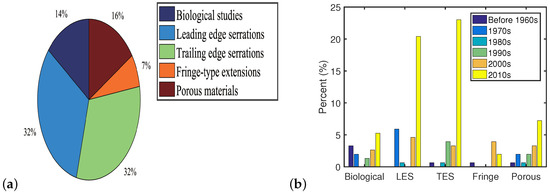
Figure 2.
An overview of the studies on bio-inspired aerodynamic noise control: (a) by categories; and (b) by years (LES and TES denote leading edge serrations and trailing edge serrations, respectively).
The remainder of this paper is organized as follows: Section 2 briefly reviews the biological studies of the owl’s silent flight. In Section 3, Section 4, Section 5 and Section 6, the progress of four main bio-inspired aerodynamic noise control techniques, i.e., leading edge serrations, trailing edge serrations, fringe-type trailing edge extensions and porous material inspired noise reduction, are systematically reviewed. Finally, we provide some concluding remarks and suggestions for future work in Section 7.
2. Biological Studies of the Owl’s Silent Flight
The aeronautical community’s interest in the silent flight of the owl is due to the fact that only the owl can fly almost silently in all the flying creatures and man-made aircraft [22]. Even for human observers, they cannot perceive the existence of a “silent” owl when the owl is gliding beyond a distance of approximately 3 m [23,24].
Fossil records show that the owl lived together with prehistoric animals, such as pterosaurs, about 75 million years ago. After a long period of evolution, the owl evolved the silent flight ability approximately 20 million years ago. From the viewpoint of natural selection and biological evolution, on the one hand, the owl prey on nocturnal creatures (such as mice and other small animals) for a living [25], thus their vision degrades while hearing enhances, which make the owl rely mainly on the weak voice to locate and track their potential prey. This requires the owl to be able to fly silently to avoid the sound of themselves to cover that of their prey, which in turn would disturb their ability to aurally locate the prey. On the other hand, typical prey of the owl has very high alertness, even a small dangerous signal would let them take evasive action and escape capture quickly. This also requires the owl to be able to identify and fly to the location of prey quickly and quietly.
The hearing of the owl’s prey is acute in the frequency ranges of 2–20 kHz. However, the owl only generate noise at frequencies below 2 kHz, no matter in gliding flight or flapping flight. Therefore, the flight of the owl is almost totally silent to their prey [22]. The first published flight noise measurements, which were conducted by Thorpe and Griffin [26,27], revealed that many species of owl (five species of small owls, three species of medium-sized owls and two species of large owls) do not generate ultrasonic noise components (relating to frequency ranges above 15 kHz) during the flapping flight phase, compared with other birds. In fact, Kroeger et al. [24] found that a significant part of the acoustical noise spectrum of the owl was shifted strongly towards the low frequency ranges below the hearing sensitive range of humans and their typical prey. However, no comparison of the measured flight noise spectrum of the owl to other non-silently flying birds was made in this study.
Neuhans et al. [28] presented a comparison of the flight noise between the tawny owl and the mallard duck. The acoustical results gave a proof that the flight noise of the former was indeed lower than that of the latter. The mallard duck generates noise in the range of approximately 3–5 kHz with its peak at around 4 kHz, while the tawny owl’s flight noise has noticeable low-frequency characteristics, which ranges from 50 Hz to 1.5 kHz, with its maximum being between 200 Hz and 700 Hz. However, the measured flight noise was recorded in a somewhat uncommon manner: the flying mallard duck was recorded outdoors while the tawny owl was measured in a large gym since the flyover noise of the owl was too low to be recorded in an outdoor environment. Moreover, no correction for different flight speeds of the duck and the owl was performed within their study, thus it was impossible to determine whether the silent flight of the owl mainly originates from low-speed flight or its evolved special morphological structures [29,30].
Recently, a horizontal 92-channel microphone array and two high-speed cameras were used by Sarradj et al. [31,32] to measure the flight noise and speeds of a barn owl and two non-silently flying species (common kestrel and Harris hawk) in an outdoor environment. During the measurement, the birds glided over the microphone array under natural flying conditions, according to their natural behavior. Noise measurement results of 50 successful flyovers showed that the barn owl produces flight noise that is 3–8 dB below that of other birds, even under similar flight speeds. The third-octave-band sound pressure level spectra of the barn owl are significantly lower than both the common kestrel and the Harris hawk at frequencies above 1.6 kHz (in fact, too low to be measured above 6.3 kHz). Since the mean flight speeds of different birds are not too different in the flying noise measurement (see Table 1), the authors drew the conclusion that “the silent flight of the owl is not only an outcome of its low flight speed but is also a direct consequence of its plumage adaptation”.

Table 1.
Summary of the flight noise test conducted by Sarradj et al. [31,32].
Geyer et al. [29,30,34] carried out aerodynamic noise measurements on the prepared wings of two species of silently flying owls (barn owl and tawny owl) and three non-silently flying birds (buzzard, sparrowhawk and pigeon) in an aeroacoustic open-jet wind tunnel [35] using a 56-channel microphone array and high resolution multichannel data acquisition systems. The advantage of this study is that the noise level can be compared at exactly the same speed. The advantages and disadvantages of the noise measurements on flying birds and prepared wings are presented in Table 2, which shows that they are complementary approaches. The results show that both owl species have a significantly lower gliding flight noise than other birds for frequency bands from 800 Hz to 16 kHz, over the whole range of flow speeds between approximately 7 m/s and 20 m/s. Moreover, the observation of 3D sound maps revealed that the noise sources of the buzzard were located near the wing tip, while they were distributed on the wing surface of the tawny owl. These studies reaffirmed the speculation of Sarradj et al. [31,32] that the silent flight ability of the owl is indeed related to the special wings and feathers characteristics, not only a consequence of the low flight speed.
Table 2.
The advantages and disadvantages of the noise measurements on flying birds and prepared wings [29,33].
The special wings and feather structures evolved by the owl, which result in silent flight, first attracted the attention of ornithologists. In 1934, Graham [20] qualitatively compared the wings and feathers of the silently flying owls with that of non-silently flying birds, and then he first reported three distinctive and unique characteristics of the owl’s wing, which were held responsible for the silent flight: (1) the leading edge serrations, as also observed by Mascha [36]; (2) the soft fringes at the trailing edge of the main wings and of some primary feathers; and (3) a fluffy down-like upper surface and a velvety lower surface on the owls’ wings, as well as thick down on their legs. In the early 1970s, Kroeger et al. [24] built a 240 m3 reverberation chamber and spent more than nine months training one specimen of the Florida barred owl to fly along a certain trajectory from the ground towards forwards food in a reproducible way. In the conducted flyover measurements, the flight speeds, as well as the emitted noise of the owl at different heights from the ground, were measured. This study confirmed Graham’s conclusions since the owl would emit sounds as strong as other flying birds if the leading edge serrations and the trailing edge fringes were removed. Moreover, the flying characteristics would also be severely damaged without these devices.
Bachmann et al. [21] performed detailed morphological measurements between the wing feathers (six remiges and six coverts) of the barn owl and the pigeon from both macroscopic and microscopic level, providing a quantitative morphological database for the systematic analysis of the owl’s silent flight. The results show that although the body weights of the barn owl and the pigeon are comparable, the barn owl’s feathers are in general larger and have lesser radiates, longer pennula, leading to a larger wingspan and wing chord. Therefore, the wing area of the barn owl is larger while the unit wing loading is lower, which in turn would allow a slow flight and high maneuverability. No serrations were found on the pigeon’s feather, while the leading edge of the 10th primary feather (p10) and the 10th greater primary covert (gpc 10) of the barn owl form comb-like serrations (see Figure 3). Fringes were observed at the edges of the feathers and wings of the barn owl due to unconnected barb endings [20,21], which were only found at the base of the pigeon’s feathers. Moreover, the owl feathers are more porous than the pigeon feathers, which could allow the airflow to pass more easily from dorsal to ventral and vice versa. Bachmann et al. [37] further used three-dimensional imaging techniques to investigate the wings and feathers of the barn owl in high spatial resolution. The results show that the profiles of each owl wing are highly cambered, especially at the proximal wing, which would induce a higher lift during flight. However, the air flow tends to separate at such wing geometries. The velvet-like texture of the owl’s feathers compensates this problem by increasing the velocity gradient near the surface and stabilizing the overall flow around the wing. These authors also found that the shape of the leading edge serrations was different to maintain a homogeneous excitation of the air flow: long serrations were found in central regions with acute tips, while shorter serrations were found at the tip of the feather but with rounded tips. The thickness of the serrations decreases while the spacing between adjacent serrations increases towards the tip of the feather.
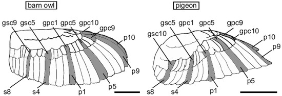
Figure 3.
Feather position in the barn owl and the pigeon (scale bar represents 10 cm), as provided by Bachmann et al. [21].
To reveal the underlying aerodynamic mechanisms of the three noise reduction characteristics of the owl, researchers carried out many exploratory studies from different viewpoints. Graham [20] emphasized that the leading edge serrations are the main apparatus in reducing the noise radiation, which gradually slows down the incoming flow through the serrations and over the upper surface of the wings, smoothing out the local pressure gradient, and thus reducing the emission of any associated noise. The trailing edge fringes allow a partial mixing of the upper and lower airflow, which prevents the formation of the noise-producing vortices. The fluffy down-like texture of the feathers allows a reduction of the noise by reducing the friction between the interlinked feathers [38] and absorbing the flight noise. Neuhaus et al. [28] indicated that the flow on the surface of the owl’s primary flying feather is essentially laminar, while the upper and lower surfaces of mallard duck’s wings have a strong turbulent flow. When the leading edge serrations of the owl’s wing are removed, the laminar flow becomes turbulent, leading to an early flow separation closer to the leading edge, thus making no noise reduction. Therefore, they believed that the leading edge serrated structure suppresses the noise generation by controlling the flow pattern.
Kroeger et al. [24] conducted extensive aerodynamics, acoustics and bionics research in an attempt to reveal the underlying mechanisms which are responsible for the silent flight of the owl, where three mechanisms were discovered: (1) The leading edge serrations behave as vortex sheet generators (not classical vortex generators), which work together with the leading edge slot and the tip feathers to keep the flow laminar and attached to the entire outer half of the wing, which could aid in suppressing turbulent boundary layer noise. (2) Compliant surfaces attenuate the turbulent boundary layer and shift the noise spectrum of the owl towards lower frequency ranges. (3) Distributed wing porosity produced by the soft downy surface thickens the chordwise boundary layer of the flow between the feathers and reduces the velocity gradients at the trailing edge, and thus reduces the trailing edge noise. Kroeger et al. [24] also used flow visualization technology on two prepared owl wings to obtain the boundary layer streamline pattern with and without the leading edge serrations. As illustrated by the results, after removing the leading edge sawtooth structure, the owl wings had a clear flow separation immediately aft of the leading edge and the flow reattached near the trailing edge, causing considerable turbulence.
Based on the work of Graham [20] and the flyover test data of Kroeger et al. [24], Lilley [22,39] gave some tentative but plausible explanations to the three special feather adaptations: (1) The leading edge serrations act as a set of nearly equi-spaced co-rotating vortex generators, which stabilizes the flow over the upper surface of the owl’s wing (evidently “pseudo-turbulent”) and prevents laminar separation. Streamwise vortices generated by each tooth drastically reduce the boundary layer thickness by providing an attached flow up to the trailing edge of the owl wing, and thus reduce the trailing edge noise since the emitted noise is proportional to the turbulent volume passing through the trailing edge. (2) The fringes at the trailing edge of the owl wings reduce or even eliminate the trailing edge noise scattering at the speed owls fly. (3) However, only with leading-edge serrations and trailing edge fringes, Lilley argued that the owl can only fly quietly but not silently compared to all other birds. Therefore, the fluffy down on the wings and legs is important to the silent flight of the owl, although it is possibly the most difficult to explain. Lilley speculated that the downy surface of the owl does not act as a sound absorber but similar to a compliant surface, which dampens the turbulent boundary layer of the airflow passing over it. Moreover, the small fibers of the fluffy down absorb the energy of small vortices in the turbulence. The result is that the owl do not generate sound at high frequencies above 2 kHz or the amplitude of the generated sound is sufficiently low to be heard by their prey since the noise generated by small scale eddies is of high frequency.
Recently, Klän et al. [40,41] studied the impact of leading-edge serrations on the flow field of a 3D airfoil model, which was derived from natural barn owl wings, through the use of advanced measurement equipment. They found that the influence of leading-edge serrations on the flow field strongly depended on the flow conditions such as the angle of attack and Reynolds number, and spanwise position also influenced the effectiveness of the serrations. Klän et al. first digitized the wings of several dead barn owls using an optical digitizer, then transformed the point clouds into polygon meshes and analyzed them with Matlab. Computed tomography scanner was used to obtain the 3D reconstruction data of the owl wing. Subsequently, they also used a confocal laser scanning microscope to digitize the leading edge serrations and the velvet-like surface, which were then assembled into 3D wing models. Finally, Klän et al. compared the flow field of the 3D models with and without serrations using Particle Image Velocimetry (PIV). The results of the PIV measurements at chord-based Reynolds number of and angle of attack (AoA) = 6° show that the average flow field at the 70% spanwise position was not affected significantly. However, the comparison of the Reynolds shear stress distribution showed that the leading edge serrations (attached to the wing in the range of 50–100% spanwise position) forced the laminar-turbulent transition, which led to an increase of boundary layer thickness. On the other hand, the mean flow field at the 90% spanwise position (closer to the wing tip) was significantly affected by the leading edge serrations: the boundary layer of the clean wing model without serrations converted from laminar flow to turbulence later, while reattached to the model earlier, and thus the length of the separation bubble was shortest while the height was largest in this case. For the wings with solid serrations, the length of the separation bubble was longer, but the height became lower, and the thickness of the boundary layer increased strongly.
Little attention is paid to the aerodynamic performance of the owl. Kroeger et al. found that the silence of owls is accompanied by a very poor flight performance, calculating a lift-to-drag-ratio of only 2.25 (less than 5) at [24]. Geyer et al. [29,42] captured the lift and drag forces of the prepared wings of five different species using a six-component-balance, at 16 different flow speeds in the range from 5 m/s to 20 m/s and seven different angles of attack (0° to 24° with a step size of 4°). The results show that the lift coefficients of the wings remain nearly constant under all tested flow speeds at zero angles of attack, and the examined owl wings produce higher lift coefficient and lift-to-drag-ratio than those of the examined non-silently flying birds. Generally, both the lift force and the drag force of the prepared wings of the barn owl continuously increase with increasing flow speed. However, the lift force starts to decrease above approximately 12 m/s due to the deformation of the wing. After removing the leading edge serrations, the deformation of the wing was slightly larger at higher angles of attack, and the lift force was lower than with the leading edge serrations intact. Therefore, Geyer et al. believed that the leading edge serrations help to reduce the deformation of the owl’s wings, thus keeping the wing shape and gliding flight more stable at high angles of attack when an owl is attacking its prey.
3. Leading Edge Serrations
As can be seen in Section 2, leading edge serrations is one of the adaptability characteristics of the owl’s wing, which is to be held responsible for the quiet flight. Therefore, leading edge serrations is seen as a source of inspiration for finding technical solutions for the development of quieter aerodynamic structures. Generally, bio-inspired simulation of the owl’s leading edge can be divided into sawtooth serrations and sinusoidal serrations (see Figure 4), both of which are proved to be effective passive flow control techniques to reduce noise.
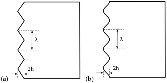
Figure 4.
Schematic of the leading edge serrations showing the parameters of wavelength and amplitude h: (a) sawtooth serrations; and (b) sinusoidal serrations.
3.1. Aeroacoustic Performance of Leading Edge Serrations
Theoretical, experimental and numerical studies (see Table 3) in the past have shown that leading edge serrations (with appropriate geometrical properties) is an effective technique to reduce noise emission [43], either laminar boundary layer instability tonal noise (trailing edge self-noise) in smooth inflow or turbulence–leading edge interaction noise in turbulent flow.
Table 3.
Selected investigations of acoustic effect of leading edge serrations (“⋯” denotes “not clear”, is the distance between the root and peak, and is the chord length).
3.1.1. Sawtooth Serrations
In the early 1970s, a series of extensive studies of the application of sawtooth serrations to the leading edge of stationary and rotating airfoils was suggested by H. J. Allen [56,57] when Director of the NASA Ames Research Center, who was aware that the noise radiated from the airfoils can be reduced by using the silent flight adaptations of the owl wing for reference. In these studies, all serrations were sawtooth with various configurations and attached on the pressure side near the leading edge of airfoils or rotor blades.
The acoustic measurements conducted by Hersh and Hayden [44] at chord-based Reynolds numbers ranging from to showed that the loud, distinct tone noise of both an airfoil and a propeller operating at low angles of attack in a smooth inflow can be definitely reduced or eliminated by using various types of sawtooth serrations attached in various positions on the pressure surface near the leading edge. The authors found that the tones were generated by laminar boundary-layer wake vortex shedding near the trailing edge of the airfoil and propeller at the examined Reynolds number range. The leading edge serrations removed virtually all the tones by generating chordwise trailing vortices which changed the boundary layer from laminar to turbulent on both pressure and suction surfaces and altered the wake vortex shedding from periodic or near periodic to broadband [58]. Arndt and Nagel [45] experimentally examined the possibility of using leading edge sawtooth serrations to reduce rotor noise in an anechoic chamber. The results indicate that the leading edge serrations could effectively reduce both rotational noise and vortex noise components under some specific configurations and running conditions. Soderman [46] investigated the acoustic effects of sawtooth serrations mounted near the leading edges of two different size rotors, operating in hover conditions under various rotor speeds, blade angles, as well as the shape and position of the serrations. He observed that the overall sound pressure level reductions varied from 4 to 8 dB for the small-scale rotor (1.52 m diameter, NACA 0012 airfoil, chord-based Reynolds number at the tip was 1.83 × 10⁵–5.5 × 10⁵) with 3.6% chord serrations, while it was only up to 4 dB for the large-scale rotor (2.59 m diameter, NACA 0015 airfoil, chord-based Reynolds number at the tip was 9.94 × 10⁵–3.18 × 10⁶).
The effectiveness of the sawtooth serrations to suppress tonal noise was sensitive to several factors, such as the geometry and location of the serrations, inflow speed and angle of attack, as well as the profile shape of the models. Hersh and Hayden [44] found that the greatest noise reduction of the NACA 0012 shaped airfoil was achieved by the deepest serration (about 1.1% chord), while the greatest reduction in noise of the two-bladed propeller was obtained by the shallow serration (about 0.75% chord). The noise measurement results on the large-scale rotor [46] revealed that the smaller serrations (0.6–1.2% chord) and serrations with spacing between prongs outperformed than the larger serration (3% chord) and the serration without spacing. However, Arndt and Nagel [45] found that the effectiveness of the serrations was strongly related to blade pitch angle and rotor speed, instead of sawtooth configurations (tooth depth and tooth tip spacing): 5 dB attenuation was realized at 6° pitch angle and 3000 Revolutions Per Minute (RPM), whereas a maximum noise reduction of 8 dB was observed at 10° pitch angle and 2000 RPM. Moreover, the positions of the serrations had a significant effect on noise reduction: the best reduction was obtained when the sawtooth serrations were located near the stagnation point (move downstream with increasing angle of attack) [46], and when they were sticking out from the surface as opposed to when they were attached flush against the surface [44]. It was also noticed [46] that the serrations were more effective at lower rotor tip speeds: up to 10 dB vortex noise reduction for the large-scale rotor at 500 RPM, and 8.5 dB reduction for the small-scale rotor at 840 RPM. In addition, high-frequency broadband noise (caused by vortex shedding and higher harmonics of rotational noise) was reduced with little effect on the low-frequency noise. Hersh and Hayden [44] observed that the noise reduction decreased at high angles of attack (see also [55]).
3.1.2. Sinusoidal Serrations
The application of sinusoidal serrations (also known as tubercles) to the leading edge of the models as a noise attenuator was partly inspired by the flipper of a humpback whale [59,60], which has enhanced maneuverability during prey capture.
Hansen et al. [47,61] found that leading edge sinusoidal serrations significantly reduced the tonal noise (emitted from boundary layer turbulence scattering at the trailing edge) of a NACA 0021 airfoil at a Reynolds number of , as well as the overall broadband noise (generated by the interaction between turbulence and the leading edge of the airfoil) surrounding the peak of the tonal noise. The most effective configurations for tonal noise elimination at = 5° were those serrations with a smaller value of ratio (smaller wavelength and larger amplitude).
Turbulence–airfoil interaction noise generated by the interaction of turbofan turbulent wakes and the outlet guide vanes is known to be the main contribution to the broadband noise emission of aero-engines during landing approach phases [62]. Generally, turbulence–airfoil interaction mechanism (the near-isotropic inflow turbulence) can be obtained by using either a turbulence grid located inside the nozzle near the outlet of wind tunnel [48,49,50,63,64] or a circular cylinder located in a tandem configuration [49,53]. Several acoustic measurements conducted in different anechoic open-jet wind tunnels revealed that a significant broadband noise reduction of turbulence–airfoil interaction noise could be obtained by almost all the modified airfoils with leading-edge sinusoidal serrations over a quite wide range of frequencies and Reynolds numbers: sound power level reduction of about 3–4 dB for the non-symmetrical NACA 65-(12)10 lifting airfoil [48,64], a maximum of about 10 dB (in grid-generated turbulence) or 5–6 dB (in the wake of cylinders) dimensionless reduction for the symmetrical NACA 0012 airfoil [49], and more than 3 dB for a flat plate [50,63].
Comparison of sound power reduction level (ΔPWL) between sinusoidal airfoil and sawtooth airfoil under the same wavelength and amplitude of the serrations by Chaitanya et al. [65] revealed that the latter provided consistently higher noise reductions than the corresponding sinusoidal case above the frequencies of , due to a lower source strength and the singular behavior near the sawtooth root.
The effectiveness of the sinusoidal serrations to suppress noise was also sensitive to several factors listed below, especially the first one, which is the focus and the most studied:
- (1)
- Serration geometry: Roger et al. [49] suggested that the key parameter for the noise reduction of NACA 0012 airfoil was the serration wavelength, however only one sinusoidal serration configuration (i.e., , and , where is the mean chord) was used in their study. Chaitanya et al. [65] found that, when the serration amplitude of two different NACA 0065 airfoil was the same, the one with wider wavelength produced less low-frequency noise but more high-frequency noise (supported by the generalized Amiet model in [66]). Both analytical [66] and experimental [50,63] studies on flat plate demonstrated that the amplitude of the serrations is a key parameter for reducing broadband noise: the level of sound power reductions generally increases with increasing serration amplitude, and wider and longer serrations obtain higher overall noise reductions [63]. However, the parameter study on a realistic NACA 0065 airfoil with the same serration profile showed that sound power reductions generally increased with increasing inclination angle ), which implied that narrower and longer serrations could achieve higher noise reductions [51] (see Figure 5). All these studies showed that noise reductions were less sensitive to the serration wavelength than the serration amplitude. A systematic parametric study on 12 sinusoidal leading edges with different wavelengths and amplitudes by Chong et al. [52] revealed that: (a) Significant laminar instability tonal noise reduction can be achieved by the sinusoidal leading edge serrations with a smaller wavelength and larger amplitude (also observed in [47,54,61]). Smaller wavelength tends to generate more streamwise vortices per unit span, while larger amplitude would produce strong streamwise vortices. Both are more effective in restraining laminar flow separation and destroying the instability of the incoming boundary layer. (b) Turbulence–leading edge interaction noise attenuation improves slowly with reducing serration wavelength (see also in numerical simulations [67,68]). However, small wavelength serrations might increase noise at frequencies greater than 10 kHz, which would translate into the corresponding overall sound pressure level, thus the smallest wavelength is not necessarily the most optimum choice. Moreover, the reduction of turbulence–leading edge interaction noise is increased (nearly linearly [63,68,69]) by increasing the serration amplitude. On the other hand, as shown by the numerical simulation results of Haeri et al. [70], this trend would reach a maximum beyond which no further increase could be achieved. Moreover, the optimal serration varies depending on the parameters of the inflow eddy, and it is clear that no one optimal serration exists that would reduce the noise for all the eddy parameters [71].
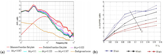 Figure 5. Typical comparison of acoustic spectra, reprinted from [63] with permission from AIP Publishing: (a) variation in amplitude (the prediction by using Amiet theory is shown in this subfigure to validate the measurement method and to establish the baseline acoustic spectra); and (b) variation in wavelength (dashed lines and solid lines for each speed denote and , respectively).
 - (2)
- Inflow speed or Reynolds number: For both the flat plate [50,63] and the NACA airfoils [48,50,54], the level of noise reduction (both boundary layer instability noise and turbulence–airfoil interaction noise) decreases as the mean flow velocities or Reynolds numbers increase (see Figure 5b), although the variations in the noise reductions are not significant.
- (3)
- Angle of attack: Chong et al. [52] showed that the best turbulence–leading edge interaction noise reduction actually occurs at the angle of attack = 0° for the modified airfoils with sinusoidal leading edge serrations, and noise reduction becomes slightly better at > 0° but less effective at < 0°. Moreover, both experimental [48] and numerical [71] studies showed that the maximum noise reduction becomes smaller with increasing angle of attack.
- (4)
- Directivity: OASPL directivity patterns of the symmetrical NACA 0012 airfoil with sinusoidal leading edges at different azimuth angles all reduced 2–5.5 dB rod–airfoil interaction noise [53], while the observations on the non-symmetrical NACA 65-(12)10 lifting airfoil at 60 m/s [48] showed that the noise reduction in the rear arc (gain of 5 dB) is higher than that in the front arc (gain of 3 dB).
- (5)
- Frequency range: Significant noise reductions are confined to the mid to high range of frequencies (typically, 500 Hz to 8 kHz) but with negligible reductions at low frequencies (below about 500 Hz) for all the examined cases [50,53,63,69].
3.1.3. More Innovative Geometries
Different from the above-mentioned leading edge serrations, where the chord changed triangularly or sinusoidally in the spanwise direction (see Figure 6a), Rostamzadeh et al. [72] proposed a novel leading edge model where the geometric angle of attack varied sinusoidally along the span (see Figure 6b). Both predictions by using Prandtl’s nonlinear lifting-line theory and wind tunnel experiments have shown that the newly proposed design had similar aerodynamic characteristics to those with conventional sinusoidal serrations. However, no acoustic measurements were presented in this work.
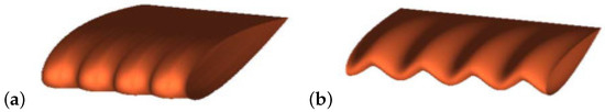
Figure 6.
Two forms of the modified NACA 0021 airfoils, reprinted from [72] with permission from AIP Publishing: (a) the chord changed sinusoidally in the spanwise direction; and (b) the geometric angle of attack varied sinusoidally along the span.
In 2016, several innovative leading-edge geometries were developed by Chaitanya et al. [65], who further modified the geometry profiles of conventional sawtooth or sinusoidal leading edge serrations, with the hope to provide substantially greater noise reductions. These innovative geometries can be classified into two categories according to their noise reduction mechanisms: control of noise radiation and control of noise source. The first category includes the double-wavelength serrations, which were made up of the summation of two single-frequency sinusoidal wavelengths of roughly the same amplitude, and the chopped-peak serrations by clipping the peak. The second category includes the leading edge slitted-root serrations where a narrow slit was added at the root position of the serrations and the leading edge slitted-V-root serrations. Acoustic measurement results confirm the effectiveness of these innovative geometries: (1) Double-wavelength serrations obtained up to 4 dB additional noise reductions around the peak of sound power level, compared to the single wavelength serrations, due to the interference between adjacent serration roots. Moreover, it was observed that, under the same wavelengths, low-frequency noise reduction of the double-wavelength serrations reduced while high-frequency noise reduction increased, as the streamwise distance between two adjacent roots increased. (2) Chopped-peak serrations increased the low-frequency noise reductions, which can be put down to the increased source strength at the clipped peak of the serrations and the enhanced degree of destructive interference between the chopped-peak and the root. (3) As shown by Chaitanya et al. [51] and Kim et al. [73], the dominant noise sources of the serrated sinusoidal leading edges in the low-frequency range are concentrated near the root of the serrations. Thus, the introduction of the leading edge slitted-root serrations reduced the pressure difference and vortex strength at these locations, which in turn increased the noise attenuations at low frequencies in the far field. Slitted-V-root serrations further eliminated the negative noise reductions at high-frequency ranges of the slitted-root serrations, which was caused by a Helmholtz resonance formed in the cavity across the narrow slits.
3.2. Aerodynamic Properties of Leading Edge Serrations
Several studies (see Table 4) have consistently shown that leading edge serrations provided more gradual stall and superior post-stall performance, i.e., to maintain higher lift without adding drag in the post-stall region and at the same time to delay the stall occurrence by increasing the lift at high angles of attack. Therefore, it is believed that leading edge serrations could be practically used to enhance the aerodynamic properties of the aircraft at takeoff or approach conditions, as well as to suppress stall on rotor and propeller blades.
Table 4.
Selected investigations of aerodynamic effect of leading edge serrations (“⋯” denotes “not clear”).
3.2.1. Sawtooth Serrations
Hersh and Hayden [44] found that the fluctuating lift (the dipole source of the acoustic tone), drag, and pitch moment levels were greatly reduced by attaching the sawtooth serrations, but no significant improvements or adverse effects in steady or average aerodynamic performance were observed. Serrations placed near the stagnation point substantially increased the slope of the lift curve by 12% for the symmetrical NACA 0015 airfoil and 22% for the camber NACA 2412 airfoil [74,84], respectively. Both drag and stall angle were not measurably increased by the serrations for either airfoil. Arndt and Nagel [45] showed that both vortex noise and rotational noise were attenuated by using leading edge serrations onto a two-foot diameter rotor, but it was accompanied by obvious losses in rotor efficiency (thrust coefficient reduced and torque coefficient increased), thus the authors believed that the practicality of the leading edge sawtooth serrations as a noise attenuator might be questionable [85].
Soderman [86] at NASA Ames systematically studied the effect of sawtooth leading edge serrations on aerodynamic performance. He found that serration size was an important parameter for determining the aerodynamic effects on a 2D wind tunnel model, while serration lean (spanwise cant angle) had very little effect: smaller sawtooth serrations (0.13% to 0.67% chord length), when properly attached tangentially to the leading edge surface of the NACA 661-012 airfoil’s pressure side, increased maximum lift by approximately 12% and angle of attack for maximum lift (i.e., stall angle) but slightly reduced the slope of the lift-curve, by generating streamwise counter-rotating vortices from each root that re-energized the boundary layer, decreased the airfoil wake thickness and delayed flow separation on the suction side at various angles of attack. On the other hand, larger serrations reduced the maximum lift since they obstructed the flow over the suction side. Maximum lift and lift-curve slope can be further improved when there is some spacing or gaps between the roots rather than immediately adjacent, however, the spacing is not as big as possible but has a suitable intermediate value. The drag was not affected by the introducing serrations at low angles of attack but was reduced at high angles of attack when the stall angle was approached. Soderman also found that serration location was the most critical parameter to performance: serrations attached as close as possible to the stagnation point region (1.25% chord) near the stall angle of attack caused the greatest increase in maximum lift (up to 21%), while the performance was degraded when the serrations were attached forward to the frontline of the airfoil. Ito [77] performed wind tunnel experiments with laminar wing models which were equipped with or without different serrated leading edges. The author found that the aerodynamic characteristics of sawtooth serrations had a strong Reynolds number effect: In the lower Reynolds number of , the sawtooth leading edges showed higher lift coefficient than the unmodified airfoil beyond = 10°, and serrations with lower wavelength had higher lift coefficient. While in the higher Reynolds number of , no significant difference was seen among the different leading edge configurations.
3.2.2. Sinusoidal Serrations
Several experimental and numerical studies have shown that all of the modified airfoils with leading edge sinusoidal serrations had lower lift coefficient slopes, stall angle and maximum lift coefficients , while mildly higher drag coefficient in the pre-stall region of the unmodified airfoils [47,51,52,54,83,87,88]. However, in the post-stall regime, airfoils with leading edge serrations produced higher lift coefficient (by as much as 25% at [81] or 50% at [75,89,90] for the NACA 634-021 airfoil, 48% for the NACA 0020 airfoil at approximately [76], or 48% for the NACA 2412 airfoil at approximately [80]), little or no drag penalty [75,80,81,89] and larger lift-to-drag ratios. Similar to the observations on sawtooth serrations, sinusoidal serrations also reduced the fluctuating lift and drag [82].
Previous studies [47,68,69,75,80,89,90,91] showed that the amplitude of the serrations had a distinct effect on the resulting aerodynamic performance, whereas the wavelength played a minor role. Lift coefficient decreased with larger amplitude at low and medium angles of attack, while it increased with larger amplitude and wavelength in the post-stall region. Over the majority of angles of attack examined, values increased with larger amplitude and wavelength. Malipeddi et al. [80] attributed these observations to the fact that the serrations with higher amplitude had less pressure at the roots and more pressure variations on the surface, which in turn significantly delayed separation and stall. Cranston et al. [79] found different effect of the serration amplitude for the small aspect ratio flat plates at . The small serrated plate showed some increase in at almost all angles, the medium serrations demonstrated similar increases in at low angles of attack but no improvements at higher angles, while the large serrations showed an overall decrease in at almost every angle of attack. However, these observations might be affected by the fact that the mean chord or the aerodynamic area was decreased with the increasing of the amplitude of the serrations. At a low Reynolds number of , an efficient numerical 3D panel method conducted by Watts and Fish [92] showed that sinusoidal leading edge serrations offered no detrimental effects at zero angle of attack, while enhanced aerodynamic performance at modest angles of attack. Yoon et al. [78] numerically studied the effect of serration ratio (the spanwise length covered by the serrations to the entire span length of the NACA 0020 airfoil) on the aerodynamic characteristics at a fixed wavelength of and amplitude of . The numerical results show that the stall occurred earlier and the lift coefficient became larger in the post-stall region as the serration ratio increased. Guerreiro [93] noticed that the aerodynamic benefits of the sinusoidal leading edge serrations were highly sensitive to the aspect ratio of the airfoils. Different from all the above studies, which focused on nominally 2D models, Miklosovic et al. [60,76] experimentally investigated the effect of the sinusoidal leading edges on the performance of a 3D scale model of an idealized humpback whale flipper in a wind tunnel (see Figure 7). The results [60] show vastly different results from 2D configurations: the presence of sinusoidal leading edges increased the stall angle of attack by nearly 40% (from = 12° to = 16.3°) and the value of maximum lift coefficient by approximately 6% (from 0.88 to 0.93) (see Figure 8a). The lift curve was largely unchanged below = 8.5°, while the slope of the lift curve decreased at = 8.5°–14.5°. Generally, the modified flipper model produced consistently lower drag coefficient (as much as 32%), except a limited range of 10.3° < < 11.8° (see Figure 8b). The authors [60] thought that the sinusoidal leading edges had higher vorticity over the surface which acted as spanwise vortex generators (also observed in [80]). These eddies re-energized the flow over the model surface and caused a greater momentum exchange within the boundary layer to attach the flow over the model surface longer (because it has more energy [80]) and delay flow separation, resulting in increased lift by preventing spanwise stall. However, Nierop et al. [94] did not agree with this speculation, since both the amplitude and wavelength of the serrations were significantly larger than the boundary layer thickness. Then, the authors developed an analytically aerodynamic model (with empirical inputs) and proposed a different mechanism: The sinusoidal leading edges locally altered the pressure distribution on the surface of the model (relatively lower and higher pressures appeared in the roots and peaks, respectively) such that the adverse pressure gradient behind the serrated roots was larger than behind the peaks, and separation occurred first behind the roots (also supported by wind tunnel experiments [75,81,88,89,90,91] and simulations [78,92,95]). Therefore, the roots stalled at lower angles of attack while the peaks stalled at higher angles of attack. Since the stall of the entire 3D model requires even the most slender section near the peaks must stall, the overall stall angle increased with a more gradual stall.
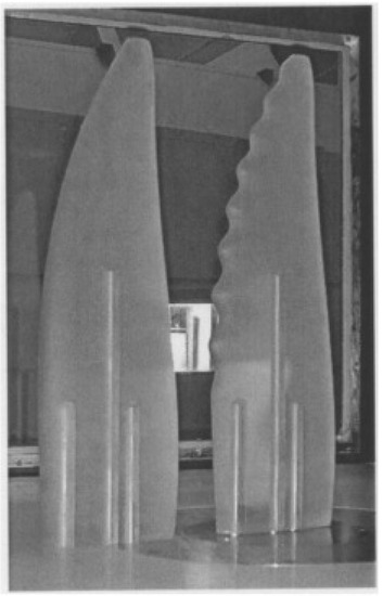
Figure 7.
3D scale model of an idealized humpback whale flipper with and without sinusoidal leading edges, reprinted from [60] with permission from AIP Publishing.
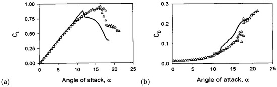
Figure 8.
Lift and drag coefficients for the baseline (solid lines) and serrated (triangles) whale flipper model, reprinted from [60] with permission from AIP Publishing: (a) lift coefficient; and (b) drag coefficient.
3.3. Flow Mechanisms Involved with the Noise Reduction by Using Leading Edge Serrations
The mechanisms responsible for the noise reduction obtained in the past generally include the generation of streamwise vortices and the reduction of spanwise correlation:
- (1)
- Vortex generators: Hot-wire measurements conducted by Arndt and Nagel [45] showed that leading edge sawtooth serrations severely dampened the mean flow and the near wake turbulence intensities at the position of 75% span and two chord lengths downstream of a two-bladed propeller. Combined with the studies of flow visualization (kerosene-burning smoke generator and stroboscopic lights), the authors suggested that the leading edge serrations along the blades acted as “vortex generators", which served to introduce small scale instabilities into the main flow and altered the turbulence structure by quickly breaking up large eddies shed from the blade tips or airfoils, resulting further in reduction of vortex noise. Another effect of “vortex generators” was that it could induce the formation of counter-rotating stream-wise vortex pairs at each root [47,54], which may trigger the laminar boundary layer “bypass transition”, reduce Tollmien–Schlichting (T-S) instability waves, and then destroy the acoustic feedback loop, which in turn further decrease or totally suppress instability tonal noise.
When turbulence impinging to the leading edge, the local sweep angle of the sinusoidal serrations (particularly in the mid-slopes regions) reduced the pressure fluctuations [56,57,69], which decreased the effectiveness of the sound source and thus the turbulence–airfoil interaction noise.
- (2)
- Spanwise correlation loss: Hansen et al. [61] compared the pressure distribution between both the unmodified and modified ( configuration) airfoils at = 5° by using a low-speed wind tunnel, and speculated that another possible explanation of tonal noise reduction was the spanwise variations in separation location: separation bubble extended over the entire span of the unmodified airfoil, while it was localized to or separated earlier behind the roots of the airfoil with serrations (the flow remained largely attached on the peaks; see also [47,54,75,89,95]). This characteristic might affect the coherence of the vortex generation, reduce the sensitivity of the boundary layer to external acoustic excitation and minimize the potential for the development of trailing edge tonal noise feedback loop (T-S waves). This characteristic might also dramatically reduce the size of the separated flow region and thus play a critical role in the corresponding improvements of the aerodynamic performance [75,81,82,89,95], i.e., higher in the post-stall region.
Numerical simulations by Clair et al. [62,64] using RANS/LES and a CAA code solving the nonlinear Euler equations in conjunction to the FW-H acoustic analogy showed that pressure distribution was almost identical away from the leading edge region, while it was noticeably different at the region of leading-edge serrations (also experimentally observed in [48]): The pressure peak and the pressure fluctuation behind the roots of the leading edge serrations were slightly amplified compared to the unmodified configuration, while they were reduced by more than a half at both the peaks and mid-slopes (see also [53]). Therefore, the pressure signals from different locations had significant phase shifts [67] and reduced spanwise correlation [69,70], which might reduce the efficiency of the interaction noise radiation.
4. Trailing Edge Serrations
Serrations can also be used on the trailing edge of airfoils or blades to reduce both broadband self-noise and instability tonal noise (see Table 5), which are known to be the dominant contributor to the overall noise emission of the state-of-the-art aircraft and wind turbines. Broadband self-noise is mostly associated with high Reynolds number flow or when tripping is used where some energy in the turbulent boundary layer will be scattered into noise at the trailing edge, while instability tonal noise is associated with low to medium Reynolds number flow where no boundary layer transition occurs on the pressure side of the baseline model’s surface. Generally, the use of trailing edge serrations can be classified into two different types: adding thin serrated flat plate inserts to the existing trailing edge and cutting sawtooth shapes directly from the sharp trailing edge (Figure 9a). Similar to leading edge serrations, the main geometrical parameters associated with trailing edge serrations are serration wavelength and serration amplitude (Figure 9b).
Table 5.
Selected investigations of acoustic effect of trailing edge serrations (“⋯” denotes “not clear”).
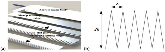
Figure 9.
Trailing edge serrations: (a) CAD drawing of the NACA 0012 airfoil model with one sharp trailing edge and three non-flat plate serrated trailing edges (reprinted from [97] with permission from Elsevier); and (b) sketch of the trailing edge serrations with definition of wavelength and amplitude h.
4.1. Aeroacoustic Performance of Trailing Edge Serrations
4.1.1. Broadband Self-Noise
The first theoretical model for the noise reducing effect of serrated trailing edges was developed by Howe [113,114] in 1991. Assuming that trailing edge serrations do not introduce other extraneous noise sources, change the surface pressure frequency spectrum and affect the turbulent eddies close to the trailing edge, Howe derived analytical noise radiation models for a flat plate airfoil with both sinusoidal and sawtooth trailing edge serrations, at zero angle of attack in low Mach number turbulent flow. It was shown that turbulent boundary layer trailing edge noise reductions of order dB for the sinusoidal profile [113] and dB for the sawtooth profile [114] are possible, at acoustic frequencies f such that , where is the main stream velocity, and h are the wavelength and amplitude of the serrations. According to Howe’s theory, the attenuation relative to that produced by the unserrated trailing edge was significant when the edges of the serrations were inclined at an angle of less than about 45° (i.e., ) to the direction of the mean flow. Moreover, the noise spectrum was shifted to lower frequencies when the amplitude h increased (see Figure 10). Noise reduction increased with increasing frequency and decreasing values of . In other words, a greater noise reduction can be obtained by narrower, shaper serrations (supported by experimental measurements of [97,100,104,115,116,117]). Comparison of the corresponding spectra between sinusoidal type serrations and sawtooth type serrations revealed that the predictions were very similar when while the latter led to greater noise reduction than the former when , due to the sharpness of the tooth at the root and peak regions of the serrations.
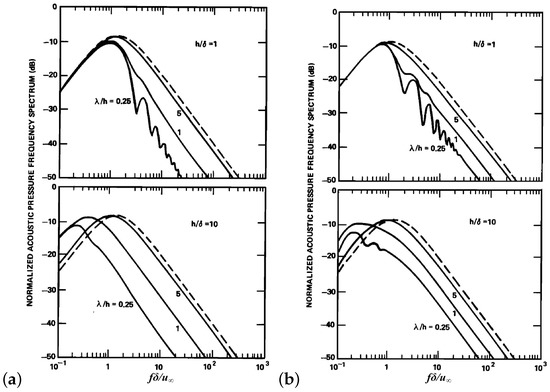
Figure 10.
Normalized acoustic pressure frequency spectrum of noise produced by different trailing edge serrations ( - - - for an unserrated edge, reprinted from [114] with permission from AIP Publishing): (a) sawtooth serrations; and (b) sinusoidal serrations.
Later, Dassen et al. [98] experimentally investigated Howe’s noise reducing potential under more realistic flow conditions and model geometries. Trailing edge serrations with an amplitude of 25 mm and wavelength of 5 mm was attached to six flat plates and eight 2D NACA airfoils of mm chord length with different geometries at high Reynolds numbers of . Comparative analysis of the radiated octave band sound pressure levels between the serrated flat plates/airfoils and the reference flat plates/airfoils showed that significant noise reductions (up to 10 dB in the range of 1 kHz to 6 kHz for the serrated flat plates) can be obtained by the serrated trailing edges. Moreover, the noise reductions of the serrated flat plates were not affected by the inclination of the trailing edge, the inclination of both the leading edge and trailing edge, or the orientations of the teeth in the chord plane. However, misalignment of the serrations with respect to the flow direction and chord plane by 15° gave rise to about 10 dB increase of the radiated noise. On the other hand, the measured noise attenuations were significantly smaller than that predicted by the theoretical model of Howe [114] (also observed in several other experimental studies [102,118,119,120,121,122]). Furthermore, the highest noise reduction was achieved at low to middle frequencies and noise increase occurred at high frequencies (see also [98,99,100,102,104,107,120,121,122]), contrary to Howe’s model that the theoretical noise reduction predictions occurred only at high frequencies . These experimental studies revealed that the assumptions and simplifying approximations made by Howe to derive the serration noise reduction model might be inaccurate [117,119,120,123].
Oerlemans et al. [99] and Hurault et al. [124] did validation measurements on the reduction of trailing edge noise from scaled wind turbine models in different anechoic wind tunnels. The results show that acoustically optimized serrated rotors could achieve 6–7 dB turbulent boundary layer trailing edge noise reduction over a variety of flow conditions, with little to no changes to aerodynamic performance. Based on these encouraging studies, Oerlemans et al. [100,125] and Hurault et al. [124] further performed acoustic measurements on full-scale wind turbines. Several parameters were considered in these works, such as wind speed, observer position and the effect of the blade roughness. The results showed that: (1) Although lower than that obtained on the model wind turbines, the full-scale wind turbines with serrated blade still obtained significant trailing edge noise reduction at frequencies below 1 kHz and high wind speeds: average overall sound power level reduction of 3.2 dB for the upwind measurements on the clean rotor, and 1.2 dB and 1.6 dB reductions for the downwind measurements on the clean and tripped rotor, respectively. (2) The serrated blade was substantially quieter than the baseline one during the downward movement, while much noisier during the upward movement.
Gruber et al. [104] and Moreau et al. [96,117,123,126] experimentally investigated the influence of different parameters on the noise reduction performance of flat plate inserted serrations. In the experiments of Gruber et al. [104], over 30 serrated trailing edges with different sawtooth geometries were tested on a NACA 65-(12)10 airfoil. Several interesting and valuable observations were found: (1) At lower frequencies (300 Hz to 400 Hz), sawtooth serrations reduced less than 1 dB noise due to the dominance of jet noise. Sound power level decreased significantly in the mid-frequency range (more than 7 dB) while increased for higher frequencies (a maximum of about 3 dB). The critical frequency f above which sawtooth serrations began to increase noise followed a Strouhal number dependency of about , where is the boundary layer thickness. (2) With increasing inflow speed or Reynolds number, boundary layer thickness decreased and thus the critical frequency f moved towards higher frequency, i.e., the frequency region where sawtooth serrations has noise reduction capability increased (also observed by Finez et al. [105] for a linear cascade of seven loaded airfoils and by Qiao et al. [107] for a cambered SD 2030 airfoil). However, the maximum noise reduction levels decreased when the inflow speed or Reynolds number was increased [96,104,105,127]. (3) Spectral shape and dependency on the angle of attack appeared to be small, compared to other parameters. (4) When the wavelength of the serrations decreased, noise reduction increased at low to mid frequencies while decreased at higher frequencies. Thus, there existed an optimal value for the serration wavelength. (5) A critical value of serration amplitude is , below which sawtooth serrations are inefficient at attenuating noise radiation since the eddies in the boundary layer are too large to be influenced by a small amplitude h, while above which significant noise reductions occur. Noise radiation efficiency decreased (see also [112]) and noise reduction frequency bands became wide with increasing , but at the same time noise increase at higher frequencies increased. On the other hand, in the experiments of Moreau et al. [96,117,123,126], two different sawtooth geometries with the same amplitude were tested on a flat plate at low-to-moderate Reynolds numbers. The results show similar but slightly different observations to the works of Gruber et al. [104], which were attributed to the significant differences between the geometry of the applied models (NACA 6512-10 airfoil vs. flat plate): (1) Both broadband noise levels and high-frequency peak due to vortex shedding from the blunt trailing edge of the reference flat plate decreased with decreasing flow speed or Reynolds number. Trailing edge serrations slightly reduced broadband noise levels (up to 3 dB) at low frequencies, produced equivalent noise levels or a minor noise increase in the mid-frequency range, while reduced up to 13 dB vortex shedding noise near the high-frequency peak. Noise radiation performance of the serrated trailing edges also appeared to follow three constant Strouhal numbers based on boundary layer thickness. However, the values were different from the study of Gruber et al. [104]. (2) The wide serrations produced larger noise reductions, since the region of low-frequency noise attenuation was much wider and the radiated noise in the mid-frequency region was approximately equal to the reference plate.
To suppress high-frequency noise increase normally observed with trailing edge serrations, Gruber et al. [128] introduced several innovative serrated-type trailing edge treatments. They showed that cutting slits into the sawtooth serrations provided an additional overall sound power reduction of up to 2 dB in the mid-frequency range (1–7 kHz) and about 4 dB in the higher frequency range (7–20 kHz), since slitted sawtooth distributed the pressure difference between the suction side and pressure side of the serrated trailing edges by introducing flow permeability and thus reduced the intensity of the cross flow in each sawtooth root [104]. Moreover, They found that noise reduction gradually improved with increasing depth and reducing the separation distance of the slits. Gruber et al. [128] also showed that random trailing edge geometry provided up to 3 dB broadband noise reduction with no significant noise increase at high frequencies since a random pattern reduced the scattering effect at the trailing edge by maximizing the length of the wetted edge and reducing the correlation lengths of trailing edge turbulence [104].
Different from all the above cases where the serrations were flat plate inserts adding into the trailing edge of the main body, Chong et al. [97,115,129] investigated the noise performance of serrations directly cutting into the main body, which offers better structural strength and integrity. The measurements showed that the cutting serrations not only obtained similar broadband self-noise reductions (2–8 dB) over a larger frequency range but also could suppress the noise increase at high frequencies caused by the flat plate inserts. However, a by-product of the directly cutting serrations was extraneous low-frequency narrowband tonal noise due to the additional vortex roll-up and shedding involving horseshoe vortices [118,130,131,132] (see Figure 11). The vortex shedding noise was produced by the bluntness of varying degrees introduced across each sawtooth side (maximum at the root while minimum at the tip) or the periodic oscillatory flow (upwash and downwash) within each sawtooth gap, and thus resulted in a large penalty for the reduction of the overall sound pressure level. Moreover, they found that the low-frequency tonal noise increased with higher flow speed and longer serration amplitude (see also [130]), while decreased when the wavelength of the serrations increases. To inhibit the growth of the vortical structures at the near wake and thus suppress these extraneous noise components originating from the gap of each sawtooth, the authors further explored a hybrid trailing edge configuration which covered the serrations with a flow-resistant woven-wire mesh screen [97,115] (see Figure 12a) or filled the gaps between adjacent teeth with porous metal, synthetic foams, or thin brush bundles [110]. The results showed significant suppression of the amplitude and frequency of the narrowband tonal noise, as well as the broadband self-noise (as compared in Figure 12b,c). However, the introduced surface roughness of the mesh screen to the sawtooth surfaces slightly increased noise level at high frequencies (around 8 kHz), and thus resulted in similar mean noise performance metric distribution to the non-meshed trailing edge serrations. On the other hand, the integration of porous material into the serrated trailing edges allowed the pressure and suction sides to “communicate”, and thus reducing the acoustic dipole strength and completely suppressing vortex shedding tonal noise at the trailing edge while maintaining the benefits of the serrations. The optimal range of airflow resistivity for the porous material at the sawtooth gaps was found to be around 10 kN.s.m−4 [133]. When the sawtooth gaps were partially filled with a thin layer of brushes, vortex shedding tonal noise was suppressed and slightly wider broadband noise reduction was achieved at mid to higher Reynolds numbers. Moreover, the overall noise performance improved with decreasing brush density.
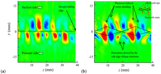
Figure 11.
Contours of streamwise vorticity (redrawn from [134]) for: (a) the baseline trailing edge; and (b) the serrated trailing edge.
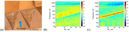
Figure 12.
Photographs of the serrated trailing edges attached with woven-wire mesh screen (a); and color maps of the ΔSPL between serrated and baseline trailing edges (b) or ΔSPL between serrated and poro-serrated trailing edges (c), where positive dB value represents noise reduction. Reprinted from [97] with permission from Elsevier.
Noise reduction mechanism when using serrated trailing edges is very complicated, as pointed out by Qiao et al. [107], since the variation in turbulence velocity fluctuating strength is different for different positions and directions. However, several aerodynamic mechanisms are candidates to explain the noise reduction in the low to mid frequency ranges and the noise increase at higher frequencies:
- (1)
- The mean pressure difference between the suction and pressure sides at the trailing edge drove the wake to start mixing together at the roots of the serrations and finally created cross flow [104]. The cross-flow increased the distance between the model surface and the suction side boundary layer (from 7.1 mm to 8 mm [102]), and thus led to a less efficient scattering source [105].
- (2)
- Flow visualization by an advanced optically active liquid crystal technique [108,134] showed that stronger turbulence existed on the predominantly sawtooth’s oblique side edges and peaks since lower surface temperatures and higher convective heat transfers existed in these regions (see Figure 13). Vathylakis and Chong [108,134] conjectured that there were convective pressure-driven spanwise vortical structures near the sawtooth side edges and amalgamation of the vortical structures on both sides near the sawtooth peaks. The interaction between these vortical structures and the local turbulent boundary layer could be an effective mechanism to redistribute the momentum transfer, turbulent shear stress, and energy spectrum, resulting in reduced convection velocity of the turbulent eddies and weakened scattering of the turbulence interaction noise.
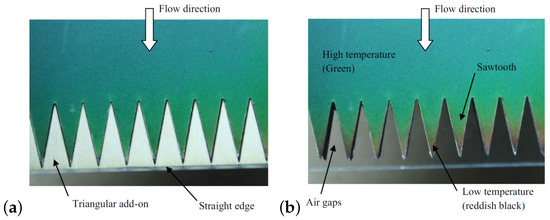 Figure 13. Captured raw active liquid crystal images (redrawn from [134], reddish black color and green color denote low temperature and high temperature, respectively) for: (a) the baseline trailing edge (serrated trailing edge with triangular add-on); and (b) the serrated trailing edge.
 - (3)
- The flow was attached on the suction and pressure sides of the serrated edges [104] and the suction side turbulent boundary layer was suppressed [105], which in turn reduced the broadband noise amplitudes and tonal noise components.
- (4)
- The particular sawtooth geometry reduced the spanwise coherence (related to the spanwise correlation length), which further reduced the noise generation efficiency. In the streamwise direction, the turbulent eddies propagated at a similar speed for both the baseline and serrated trailing edges. In the spanwise direction, on the other hand, no convection velocity or any discernible difference in phase spectra existed for the baseline trailing edge, but noticeably different spanwise coherence and phase spectra functions were presented for the serrated trailing edges [108,134,135].
- (5)
- The cross flow through the roots between adjacent teeth increased turbulence activity and produced small jets [136], which were believed to be the reason for high-frequency noise increase [104].
4.1.2. Instability Tonal Noise
Serpieri et al. [109] investigated the effectiveness of the serrated geometries with flat plate inserts to reduce the laminar boundary layer instability noise at low to moderate Reynolds numbers (3.33 × 10⁵–4.66 × 10⁵). Experimental results show that pressure side instability was the main cause of the instability noise emission for the free transition NACA 0018 airfoil and trailing edge serrations could reduce up to 40 dB acoustic emission.
Chong et al. [101,103,129] presented an acoustical study of the use of directly cutting serrated trailing edges to control instability tonal noise under different low to medium Reynolds numbers and angles of attack, with the aim to establish the causal link between the spectral properties of the radiated tones and the separation bubbles on the pressure side of the NACA 0012 airfoil. The results show that trailing edge serrations did not alter the streamwise pressure gradient, but triggered a bypass transition of the laminar boundary layer into turbulence and suppressed the length of the separation bubble near the serrated trailing edges, resulting in reduced amplitude and tonality of the radiated noise.
Several studies showed that the effectiveness of trailing edge serrations to reduce instability tonal noise was sensitive to several factors: (1) Instability tonal noise attenuation improved with increasing flow speeds or Reynolds numbers [101,103] when the serrations were directly cut or decreased with increasing flow speeds when thin serrated flat plate inserts were added [109]. (2) Tonal noise reduction was more effective at a larger angle of attack [101,103], since the onset of the boundary layer separation bubble at the NACA 0012 airfoil’s pressure side had moved downstream with increasing angle of attack, which led to a smaller bubble length or total amplification factor of the T-S wave. (3) When the ratio between the wavelength and amplitude of serrations was the same, the one with larger amplitude produced less instability noise [101,103,109] since more separation regions were affected under this situation. On the other hand, when the amplitude of the serrations was the same, the one with wider wavelength or larger oblique angle would further suppress the broadband hump and the discrete tones (see also [96,123]). This conclusion is contrary to the theoretical study of Howe [114] who pointed out that serration oblique angle of less than 45° was necessary for the reduction of broadband self-noise for the sawtooth trailing edges. The authors speculated that the reason may be due to the fundamentally different generation mechanisms [101]: The generation mechanism of the instability tonal noise is related to the aeroacoustic feedback loop at the pressure side, which involves the diffraction of the two-dimensional T-S waves at the vicinity of the sharp trailing edge. When the serrations have a larger oblique angle, the incoming T-S waves have an overall shorter “edge” or separation bubble to be amplified sufficiently in the boundary layer and further be scattered into discrete noise, which resulted in a larger tonal noise reduction.
To explore the instability tonal noise attenuation mechanism of the trailing edge serrations, researchers [106,109,129] employed several advanced flow field measurement techniques, including surface mounted hot-film arrays, hot-wire anemometry and PIV. The results of the surface mounted hot-film sensor arrays [106,129] showed that the onset of the boundary layer separation was located at around 83% chord length for the baseline NACA 0012 airfoil at and geometrical angle of = 15°. Chong et al. also found that the mean and fluctuating velocity profiles [129] and boundary layer patterns [106] before the root of the serrated trailing edges were not affected (also supported by the numerical investigation of Jones and Sandberg [118]), and thus they attributed the reduction of the instability noise to the dynamics of local flow within the serrated region. Hot-wire anemometry measurements [106,129] showed that the near wall flow over serrated trailing edges was more turbulent (greater velocity excess and turbulence intensity) than those of the straight edge, thereby shorting the separated region, influencing the radiation and further providing reductions of the instability noise since the existence of a separated boundary layer near the pressure side of the trailing edge acted as an amplifier for the incoming T-S waves and thus was considered as one of several pre-requisite conditions required for the production of the instability tonal noise [137,138]. More detailed PIV measurements [106,109] showed that the wakes generated by the sawtooth geometries were mostly turbulent in character with little distinguishable periodical structures, which helped to eliminate any wake-based noise source in the aeroacoustic feedback models in [139,140]. Moreover, the results of PIV in both span configuration and streamwise configuration showed that the serrations strongly reduced the coherence of the shed instability T-S waves of the transitional flow past the trailing edge [106,109].
4.2. Aerodynamic Properties of Trailing Edge Serrations
Comprehensive studies (see Table 6) showed that the aerodynamic performance of trailing edge serrations relied on the applied model, flow speed, angle of attack, and geometrical characteristics of the serrations.
Table 6.
Selected investigations of aerodynamic effect of trailing edge serrations.
Measurements of the pressure distribution along the chord and wake velocity downstream of the asymmetric NACA 65-(12)10 airfoil [102] showed that both lift and drag coefficients were not significantly influenced by the introduction of trailing edge serrations (see also [99,124] for wind turbine models). However, the measurements on a linear cascade made of 7 NACA 65-(12)10 blades showed that the loading was not affected in the presence of the serrations but the drag coefficient was increased by 14% [105]. Moreover, directly aerodynamic lift and drag measurements [83,131,132,136] by using a force balance showed that NACA 65-(12)10 airfoil attached with different sawtooth serrations reduced up to 15% lift coefficient over the angles of attack ranging from −5° to about 10°, compared to the baseline airfoil with the same surface area, while increased the lift coefficient in the pre-stall region. Sawtooth serrations increased the drag coefficient at angles of attack larger than 10° and more drag was produced by the serrations with increasing wavelengths.
The aerodynamic lift and drag measurements on the symmetric NACA 0012 airfoil [83,131,132,136] showed noticeably different behavior to that of the asymmetric NACA 65-(12)10 airfoil: The effect of sawtooth serrations on lift coefficient was less significant, especially at lower speeds and smaller angles of attack (from 0° to 9°). Serrations decreased the maximum lift coefficient over the critical angle region (from 12° to 15°) but improved the lift performance at deep stall region (from 17° to 20°). Moreover, NACA 0012 airfoil with serrations generally produced lower drag than that of the baseline airfoil with the same surface area.
Knepper and Garry [141] investigated the effect of trailing edge 60° sawtooth serrations ahead of a single slotted flap on the aerodynamic forces of a multi-element airfoil configuration. Measurements on both a generic flat plate model and a 2D high lift model indicated that trailing edge serrations could enhance slotted flap performance across a range of flap lap/gap settings and flap deflections. Flap lift coefficient increased up to 17% and this effect diminished with increasing flap deflection angles. The effect on the flap drag coefficient was found negligible.
Different from all these cases where static serrated airfoils were used, Gharali et al. [142] investigated the effect of a dynamic serrated airfoil (i.e., the airfoil with serrated trailing edges is subjected to highly oscillating angles of attack, which is typical behavior for a wind turbine under field operating conditions). The results show that the lift values of the serrated case were within reasonable agreement with the original airfoil at low angles of attack, while the dynamic stall angle changed from 18.5° to 19.5°, which led to higher lift values close to the dynamic stall angle.
5. Fringe-Type Trailing Edge Extensions
The basic idea behind the introduction of fringe-type (brush-type or slit) trailing edge extensions is inspired by the trailing edge fringes at the primary feathers of some owl species (see Table 7).
Table 7.
Selected investigations of acoustic effect of fringe-type trailing edge extensions (“⋯” denotes “not clear”).
The noise reduction capability of various closely spaced fringe-type trailing edge extensions was tested in DLR’s open jet aeroacoustic wind tunnel in Braunschweig (AWB) at comparatively high chord-based Reynolds numbers of 2.1 × 10⁶ to 7.9 × 10⁶ (for the flat plate [143,147]) or 1.1 × 10⁶ to 1.6 × 10⁶ (for the 2D NACA 0012-like airfoil [144,148]) (see Figure 14). Noise measurement results by using a directional elliptical acoustic mirror showed that the examined fringe-type trailing edge devices led to a significant reduction of both broadband turbulent boundary layer trailing edge noise (in excess of 10 dB within the sensitive frequency range of human perception) and narrow-band vortex shedding noise (up to about 14 dB) due to finite trailing edge bluntness, for all the tested Reynolds numbers and plate lengths. Acoustic measurements on a cambered NACA 65(12)-10 airfoil at chord-based Reynolds numbers of 1.73 × 10⁵ to 3.47 × 10⁵ showed that a relatively low maximum noise reduction of 3 dB was achieved around 600–2000 Hz by a single row of flexible polypropylene fibers, due to the high curvature of the incident flow and a strong secondary emission of the leading edge acoustic source [145].
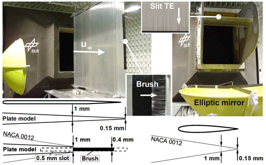
Figure 14.
Experimental setups in the AWB test section with example of trailing edge brush or slit devices, reprinted from [148] with permission from Springer.
Several studies revealed that the noise reduction characteristics of different brush or slit configurations were mostly related to the geometry parameters of the trailing edge extensions (spacing, length, and diameter), rather than on the flow conditions (flow speed, angle of attack, etc.). Herr and Dobrzynski [143,147] conducted a comparison of the respective noise reduction potential for different brush lengths and fiber diameters on a flat plate model. They summarized that the highest low frequency (1.6–2.5 kHz) noise reduction was achieved for a medium length brush (30 mm) with the thickest fiber diameter of 0.5 mm, while more promising mid to high-frequency noise reduction was provided by medium diameter brushes (0.4 mm) with longer length (30 mm to 60 mm). A further investigation on the NACA 0012-like airfoil [144,148] revealed that: (1) A flexible brush was generally more favorable than a stiff brush (also observed in [149,150]), but not essential since the latter could also achieve a noise reduction. (2) The mean spacing of the adjacent fiber materials was the crucial design parameter for either a brush-type trailing edge or a solid slit trailing edge: small fiber spacing (<1 mm) provided a significantly increased noise reduction capability (also noticed in [128]) (see Figure 15). (3) Longer brush-type or slit configurations (exceeded a minimum fiber length of about 15 mm) led to better noise reduction since they became more flexible and provided a larger flow-permeable region to achieve the desired hydrodynamic absorption. (4) When the fibers were not oriented along the flow direction, excess broadband noise increase of about 2 dB was observed. (5) The achievable noise reduction was irrespective of the flow velocity, in the examined range of Reynolds numbers. (6) The brush-type trailing edges nearly did not affect the noise spectra by changes in angle-of-attack, and thus the overall noise reduction appeared to diminish with a growing angle-of-attack since the noise emission of the solid reference NACA 0012-like airfoil significantly decreased in the mid-frequency range. Sudhakaran et al. [146] found that when the open-area ratios of the slit trailing edge were the same, noise reduction increased with decreasing slit separation or increasing number of slits.
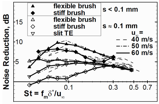
Figure 15.
Effect of fiber spacing s on the noise reduction of NACA 0012-like airfoil, reprinted from [148] with permission from Springer.
Similar to trailing edge serrations, broadband excess noise contributions at high frequencies (>10 kHz) were also analytically predicted or experimentally observed for the brush-type [143,147] or slit [122,146] devices. Herr and Dobrzynski [143,147] speculated that this effect may be due to the decrease of the spanwise correlation scale, which is introduced by the transformation of spanwise vorticity into streamwise vorticity. On the other hand, Finez et al. [145] suspected that excessive high-frequency noise components might be linked to the micro-jets through fibers.
Up to now, the effect of fringe-type devices on the aerodynamic performance has not been experimentally tested. Ortmann and Wild [151,152] numerically studied the effect of two different stiff brush-type devices (cylindrical or rectangular) at the realistic A340-type slat trailing edge on the flow field and force coefficients. The results showed that cross vortex caused by the design-related steps at the root of the cylindrical brush hairs impaired the flow around the slat trailing edge and thus adversely affected the aerodynamic properties, i.e., reduced the lift coefficient while increased the drag coefficient, especially when the length and diameter of the brush hairs were increased. On the other hand, brushes with a rectangular cross-section (i.e., slit trailing edges) had only a minor influence on the slat wake and momentum loss, and thus the loss of lift coefficient was insignificant compared to the reference slat trailing edge configuration.
Several candidate mechanisms can be used to explain the underlying noise reduction capabilities of fringe-type trailing edge extensions: (1) Brush devices smoothed down the abrupt change of a solid trailing edge interacting with the unsteady boundary layer turbulence [143] due to their permeability, and broke-up turbulent eddies that can efficiently radiate noise, thus leading to a reduction of the edge noise generation. (2) Brush edge extensions aligned automatically with the trailing edge flow and thus increased the compliance, which further weakened the diffraction effect at the trailing edge [153]. (3) Flow permeable brush extensions reduced the turbulent flow pressure amplitudes and unsteady turbulent velocities through viscous damping in the flow-permeable region [143,144]. (4) Brush devices induced a transformation of spanwise vorticity into streamwise vorticity [143], de-correlated both spanwise and time correlation scales of the trailing edge vortical structures [145], and thus affected the local flow field in the source area.
6. Porous Material Inspired Noise Reduction
The aeroacoustic effects of a soft and elastic downy upper surface of the owl’s wings and legs are equivalent to an increased permeability to air, thus another bio-inspired aerodynamic noise control technique is to investigate the effects of using different porous materials that have open and mutually interconnected pores for the construction of objects and the subsequent reduction of noise emission. An overview of the acoustic effect studies of porous material inspired noise reduction is listed in Table 8.
Table 8.
Selected investigations of acoustic effect of porous material inspired noise reduction (“⋯” denotes “not clear”).
A noteworthy early (1968) systematic study on the use of porous materials to reduce the “vortex shedding noise” radiated by blade trailing edge in axial flow compressors was conducted by Potter [155]. Experimental results showed that the average decrease in overall sound pressure level was generally less than 1 dB for all the studied Reynolds numbers. The most significant noise attenuation was obtained by a highly porous trailing edge whose last 25% of the chord was replaced by 20% density “foam-metal” nickel: up to 2.6 dB or 3.1 dB overall sound pressure level decrease was obtained when the compressor blades were in a laminar flow or turbulent flow, respectively.
Fink and Bailey [156] found that porous surface treatment using reticulated vitreous carbon material (80 pores per inch, acoustic impedance of 40 rayls) could reduce considerable noise radiation from a NACA 23012 airfoil with a 40° deflected single-slotted flap: up to 1–2 dB or 2–3 dB reduction of total far-field noise was obtained over several octaves of frequency when the porous modification was applied to the side-edges (also observed in [162]) or the leading edge of the flap, respectively. Sueki et al. [154] also found that the aerodynamic noise radiated from cylinders and high-speed pantographs can be reduced by covering their surface with particular porous materials. Numerical results of Lee [163,164] showed that porous leading edge could suppress pressure fluctuations during the blade-vortex interaction of the helicopter and consequently reduce the amplitude of blade-vortex interaction noise by up to 20–30%. To meet airworthiness requirements, such as thermal and chemical stability, mechanical resistance and maintainability, Herr and Reichenberger [160] proposed using sheets of duo-layer metal mesh to reduce noise at a slat trailing edge. The materials combine a coarse metal supporting structure with a fine, hydraulically smooth porous cover material, such as micro-perforated sheet metal, thin metal mesh, etc. Measurement results using a directional microphone system showed that the proposed design could reduce up to 4 dB broadband trailing edge noise in 1/3-octave band spectra or up to 8 dB peak noise.
Several studies showed that not only the overall SPL but also the characteristics of the noise spectrum depend on the porous properties. Chanaud [165] found that noise reduction increased with decreasing density of the fully porous propeller fan blades: 5 dBA, 6–10 dBA and 20 dBA reduction of sound level were achieved by 40%, 20% and 10% dense porous “felt metal”, respectively. Bae [157,166] numerically found that when the porosity is fixed to 0.25, porous trailing-edge of a flat plate with a certain range of normalized permeability (e.g., 0.01) could reduce the tonal peak of the turbulent noise by up to 13 dB, while with other permeability no significant noise reduction could be yielded. Sueki et al. [154] found that noise reduction ability of porous materials seems independent of the material hardness since porous urethane and porous metal have the same level of noise reduction when they have the same porosity and pore densities. However, a numerical study of Jaworski and Peake [167,168] showed that the combined effects of the elasticity and porosity of a semi-infinite poro-elastic plate produced the weakest edge amplification at low frequencies, as compared to a rigid and non-porous edge or a rigid, porous case. Geyer et al. [158] found that improved trailing edge noise reduction can be obtained with increasing flow resistivities of the porous materials (see also [169]), especially for low and medium frequencies, as shown in Figure 16. On the contrary, detailed acoustic measurements by Geyer et al. [159] using a planar 56-channel microphone array showed that noticeable reduction of turbulence–leading edge interaction noise can be obtained by porous airfoils with decreasing air flow resistivities. For the micro-perforated plates configurations, Herr et al. [161] found that small values of local flow resistivity at the trailing edge led to larger noise reduction while noise reduction diminished for larger local flow resistivities. Geyer et al. [170] investigated the generation of trailing edge noise of partially porous airfoil models with varying chordwise extents of the porous material, by simply covering the main part of the fully porous airfoils used in [158] with a thin impermeable foil. They also found that a noticeable broadband trailing edge noise reduction at medium frequencies can be obtained even when 5% chordwise porous extent was used, and noise radiation decreased with increasing porous extent. Geyer et al. [158] found that the dependence of the measured noise reductions on the angle of attack was very complex in their examined range of angles, while Herr et al. [160,161] identified that noise reduction dramatically decreased with increasing angles of attack. Noise reduction decreased with increasing flow speeds or Reynolds numbers [158,160,169], which is unfavorable with regard to a full-scale application.
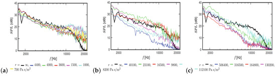
Figure 16.
Sound pressure level at = 0° and m/s, reprinted from [158] with permission from Springer.
Several studies [154,155,160,171,172,173] showed that porous modified objects reduced the lower frequency broadband sound, while increased the higher frequencies sound (starting at approximately 10 kHz) which might be due to any surface roughness introduced by the porous materials since high-frequency noise levels increased for relatively larger pores [154] or decreasing flow resistivities [171,172,173].
Aerodynamic measurements showed that porous airfoils generated a smaller lift force but a higher drag force. At the same time, the normalized lift fore increasing while the normalized drag force decreasing with increasing flow resistivity [158,174] and with decreasing chordwise [169,170] or spanwise [175] extents of the porous materials. Therefore, to take acoustic advantages (low trailing edge noise) of the porous airfoils, without significantly affect aerodynamic performance (high lift and low drag), partially porous airfoil models made of materials with medium flow resistivities (about 8.2–316.5 kPa s/m2) are favorable.
Several candidate mechanisms can be used to account for the reduction of sound generation by using porous materials: (1) When oscillatory fluid passed through the pores of the porous materials, edge-scattered near-field acoustic energy was absorbed by the viscous and thermal losses [174]. However, this contribution was restricted to high frequencies, due to the generally small dimensions of the absorbers [160]. (2) Several numerical and experimental studies showed that material-dependent porous treatments allowed the communication of the flow among the pressure side, suction side and back-end boundary layer, which equalized the dynamic pressure differences or reduced the pressure fluctuating near the leading edge [163,164], trailing edge [155,156,161,174,176] and the flap side-edges [162], and thus weakened the strength of the coherent vortex shedding, as well as the edge-scattering of the convecting eddies. This mechanism was partly confirmed by the experimental observation of Herr et al. [161], where noise reduction benefit fully diminished when either the lower or the upper surface of the porous treated region was sealed with masking tape. (3) Porous materials considerably reduced the spatial correlation length of the pressure fluctuations in both streamwise and spanwise directions, resulting in a significantly weaker strength of the dipole noise source [157,166]. (4) Porous treatments provided an approximately gradual or continuous edge impedance matching of the boundary conditions to free air [160], and then influenced the aerodynamic acoustic feedback mechanism of the trailing edge noise [169].
7. Conclusions and Future Work
It is well-known that many species of owl have the unique ability to fly silently, which has been confirmed by noise measurements on both flying birds in the field and prepared wings in the wind tunnel. Both qualitative comparison in macroscopic level and recently quantitative measurements in microscopic level have revealed that owls’ quiet flight ability is attributed to three adaptability characteristics of their wings: leading edges serrations, trailing edges fringes, and the velvety down feathers on the surface of wings and legs. The gained knowledge from the biological studies of the owl’s silent flight was later used for developing several advanced noise reduction concepts, e.g. serration-type noise reduction techniques (leading edge serrations and trailing edge serrations), fringe-type noise reduction techniques, and porous material inspired noise reduction techniques. In these techniques, fringe-type (brush-type or slit) trailing edge extensions can be considered as porous extensions due to their porous nature, as well as extreme cases of serrations with infinitely sharp tip-angles or nearly zero wavelengths. Many theoretical, numerical and experimental studies reviewed above have demonstrated that these bio-inspired devices are effective means for noise reduction, in the order of up to about 10 dB attenuation, depending on configuration and frequency. Parameter influence, aerodynamic effects and underlying mechanisms of these concepts were also studied, and the accumulated knowledge used as add-on solutions to guide a wide range of technical applications: on aircraft’s high-lift systems, cooling or computer fans, rotors, and propellers, turbomachinery or wind turbine blades, to point out a few of them.
However, it should be noted that bio-inspired aerodynamic noise control techniques are not mature enough, and faulty application may even result in increases of the radiated sound, e.g., misalignment of the trailing edge serrations with respect to the flow direction gave rise to a noise increase of about 1–5 dB [98], and a leading edge slat with a serrated trailing edge that is 1–2 dB louder [156]. Therefore, there are still several details or directions to be improved and developed in the future in terms of the actual engineering realization of these innovative techniques:
- (1)
- At present, it is not known how to determine the relevant design parameters and the respective scaling laws for a future application of the bio-inspired noise reduction devices. A viable path towards this direction is to make use of advanced measurement types of equipment such as three-dimensional surface digitizing camera and laser-scanning electron microscopy, to give a very detailed geometric description of the owl’s feathers, and then use these criteria to guide or narrow the settings of the various parameters.
- (2)
- As demonstrated in the above review, most of the previous investigations of the bio-inspired noise control techniques focused on cases with relatively low Reynolds numbers of . It is still an open question whether these potential techniques still work for future technical applications of comparatively higher Reynolds numbers since Reynolds numbers for modern commercial aircraft can be on the order of several billions (for example, Boeing 747: [37]).
- (3)
- Despite the number of studies from different research groups on the underlying physical mechanisms responsible for the owls’ silent flight and the proposed bio-inspired control techniques, no consistent understanding has been reached and thus further investigations are required prior to a recommendation for prospective full-scale applications. Future experimental studies will have to include detailed simultaneous measurements of the spatiotemporal source information (velocity and pressure fluctuations) in terms of the unsteady flow using more advanced measurement techniques such as high-speed PIV and Pressure Sensitive Paint (PSP), and its effect in the acoustic far field.
- (4)
- Up to date, the materials used in the porous material inspired noise reduction devices generally have the same porosity or flow resistivities. However, airfoils or blades with variable impedance are an attractive research direction in noise reduction. Thus, to obtain a smoother rate of change regarding the impedance of the acoustic treatment, the level of porosity should ideally have a gradual decrease towards the tip of both the leading edge and the trailing edge.
- (5)
- Thus far, noise measurement experiments are generally carried out in low turbulence acoustic wind tunnels. However, in real situations, turbulence may change in a larger range, especially for wind turbines that may operate over various atmospheric conditions in the field. Therefore, it is another meaningful direction to assess the effectiveness of the bio-inspired noise reduction techniques in laboratory experiments under a range of more realistic turbulent inflow conditions, which can be generated by different turbulence grids installed inside the nozzle or circular cylinders ahead of the models.
- (6)
- No matter the serration-type technique, fringe-type technique, or porous material inspired technique, they have mimicked only one of the three adaptive noise reduction characteristics of owl wings. However, the root cause of owl’s silent flight ability is more likely to be a combination of these three characteristics, and thus how to combine or couple together the existing bio-inspired techniques to get better noise reduction goals is an interesting subject of further investigations.
- (7)
- Finally, we can see from the above review that an increase in high-frequency noise was often observed, although low and medium frequency noises were reduced. Understanding the underlying reason for this phenomenon is good for further noise reduction and improving the design of the bio-inspired control techniques. Moreover, several studies have shown that the potential noise gains were often accompanied by a decrease in aerodynamic performance, especially in the pre-stall region. Therefore, another future work for a widespread industrial application will have to balance the acoustic benefits (low noise generation) against the aerodynamic efficiency, as well as structural, manufacturing, safety and maintenance cost issues.
In conclusion, the bio-inspired noise control techniques reviewed in this paper have the potential to achieve low-noise radiation. Although there are several challenging issues that have to be considered and solved to satisfy the requirements of more stringent airworthiness and security standards, we believe that with the progress and improvement in these areas, these techniques will gradually be applied to numerous areas of engineering.
Author Contributions
All authors substantially contributed to this work. Y.W. conceived the topic and basic framework. Y.W. wrote the original draft; K.Z. and Y.-B.S. gave professional advice and edited. All authors helped with conducting the literature survey and gave final approval of the version to be submitted and any revised versions.
Funding
This work was sponsored by the National Natural Science Foundation of China, under the grant number 11602290.
Acknowledgments
The authors want to thank the editor and anonymous reviewers for their helpful comments and suggestions.
Conflicts of Interest
The authors declare no conflict of interest.
References
- Lockard, D.P.; Lilley, G.M. The Airframe Noise Reduction Challenge; Technical Report NASA Technical Memorandum, No. TM-2004-213013; NASA Langley Research Center: Hampton, VA, USA, 2004.
- Hileman, J.I.; Spakovszky, Z.S.; Drela, M.; Sargeant, M.A. Airframe Design for Silent Aircraft. In Proceedings of the 45th AIAA Aerospace Sciences Meeting and Exhibit, Reno, Nevada, 8–11 January 2007. AIAA Paper 2007-0453. [Google Scholar]
- Hall, C.A.; Schwartz, E.; Hileman, J.I. Assessment of Technologies for the Silent Aircraft Initiative. J. Propuls. Power 2009, 25, 1153–1162. [Google Scholar] [CrossRef]
- Zhu, W.J.; Shen, W.Z.; Sørensen, J.N.; Leloudas, G. Improvement of airfoil trailing edge bluntness noise model. Adv. Mech. Eng. 2016, 8, 1–12. [Google Scholar] [CrossRef]
- Pascioni, K.A.; Cattafesta, L.N. Aeroacoustic measurements of leading-edge slat noise. In Proceedings of the 22nd AIAA/CEAS Aeroacoustics Conference, Lyon, France, 30 May–1 June 2016. AIAA Paper 2016-2960. [Google Scholar]
- Doolan, C.J.; Moreau, D.J.; Brooks, L.A. Wind Turbine Noise Mechanisms and Some Concepts for its Control. Acoust. Aust. 2012, 40, 7–13. [Google Scholar]
- Zhu, W.J.; Shen, W.Z.; Barlas, E.; Bertagnolio, F.; Sørensen, J.N. Wind turbine noise generation and propagation modeling at DTU Wind Energy: A review. Renew. Sustain. Energy Rev. 2018, 88, 133–150. [Google Scholar] [CrossRef]
- Moritoh, Y.; Zenda, Y. Aerodynamic Noise of High-Speed Rail-Way Cars. Jpn. Railw. Eng. 1994, 130, 5–9. [Google Scholar]
- Cattafesta, L.N.; Sheplak, M. Active Flow Control Actuators. Ann. Rev. Fluid Mecb. 2011, 43, 247–272. [Google Scholar] [CrossRef]
- Wolf, A.; Lutz, T.H.; Wurz, W.; Kramer, E.; Stalnov, O.; Seifert, A. Trailing Edge Noise Reduction of Wind Turbine Blades by Active Flow Control. Wind Energy 2015, 18, 909. [Google Scholar] [CrossRef]
- Sun, Y.Y.; Liu, Q.; Cattafesta, L.N.; Taira, K.; Ukeiley, L. Effects of sidewalls and leading-edge blowing on flows over long rectangular cavities. AIAA J. 2019, 57, 106–119. [Google Scholar] [CrossRef]
- Zhao, K.; Yang, X.; Okolo, P.N.; Wu, Z.; Bennett, G.J. Use of dual planar jets for the reduction of flow-induced noise. AIP Adv. 2017, 7, 025312. [Google Scholar] [CrossRef]
- Zhao, K.; Alimohammadi, S.; Okolo, P.N.; Kennedy, J.; Bennett, G.J. Aerodynamic noise reduction using dual-jet planar air curtains. J. Sound Vib. 2018, 432, 192–212. [Google Scholar] [CrossRef]
- Inasawa, A.; Ninomiya, C.; Asai, M. Suppression of Tonal Trailing-Edge Noise From an Airfoil using a Plasma Actuator. AIAA J. 2013, 51, 1695–1702. [Google Scholar] [CrossRef]
- McAuliffe, B.R.; Yaras, M.I. Passive Manipulation of Separation-Bubble Transition Using Surface Modifications. J. Fluids Eng. 2009, 131, 021201. [Google Scholar] [CrossRef]
- ACARE-Advisory Council for Aeronautics Research in Europe. European Aeronautics: A Vision for 2020: Meeting Society’s Needs and Winning Global Leadership; Technical Report Report of the European Commission; European Comission: Brussels, Belgium, 2001. [Google Scholar]
- ACARE-Advisory Council for Aeronautics Research in Europe. Flightpath 2050 Europe’s Vision for Aviation; Technical Report Report of the High Level Group on Aviation Research, Report of the European Commission; Uropean Comission: Brussels, Belgium, 2011. [Google Scholar]
- Lu, Y.X. Significance and Progress of Bionics. J. Bionics Eng. 2004, 1, 1–3. [Google Scholar]
- García-Serna, J.; Pérez-Barrigón, L.; Cocero, M.J. New Trends for Design towards Sustainability in Chemical Engineering: Green Engineering. Chem. Eng. J. 2007, 133, 7–30. [Google Scholar] [CrossRef]
- Graham, R.R. The Silent Flight of Owls. J. R. Aeronaut. Soc. 1934, 286, 837–843. [Google Scholar] [CrossRef]
- Bachmann, T.; Klän, S.; Baumgartner, W.; Klaas, M.; Schröder, W.; Wagner, H. Morphometric Characterization of Wing Feathers of the Barn Owl (Tyto Alba Pratincola) and the Pigeon (Columba Livia). Front. Zool. 2007, 4. [Google Scholar] [CrossRef]
- Lilley, G.M. A Study of the Silent Flight of the Owl. In Proceedings of the 4th AIAA/CEAS Aeroacoustics Conference, Toulouse, France, 2–4 June 1998. AIAA Paper 1998-2340. [Google Scholar]
- Gruschka, H.D.; Borchers, I.U.; Coble, J.G. Aerodynamic Noise Produced by a Gliding Owl. Nature 1971, 233, 409–411. [Google Scholar] [CrossRef]
- Kroeger, R.A.; Gruschka, H.D.; Helvey, T.C. Low Speed Aerodynamics for Ultra-Quiet Flight; AFFDL-TR-71-75; U.S. Air Force Flight Dynamics Lab.: Wright-Patterson Air Force Base, OH, USA, 1971.
- Taylor, I. Barn Owls: Predator-Prey Relationship and Conservation; Cambridge University Press: Cambridge, UK, 1994. [Google Scholar]
- Thorpe, W.H.; Griffin, D.R. Lack of Ultrasonic Components in the Flight Noise of Owls. Nature 1962, 193, 594–595. [Google Scholar] [CrossRef]
- Thorpe, W.H.; Griffin, D.R. The Lack of Ultrasonic Components in the Flight Noise of Owls Compared with Other Birds. IBIS 1962, 104, 256–257. [Google Scholar] [CrossRef]
- Neuhaus, W.; Bretting, H.; Schweizer, B. Morphologische und funktionelle Untersuchungen uber den “lautlosen’ Flug der Eulen (Strix aluco) im Vergleich zum Flug der Enten (Anas platyrhynchos). Biol. Zentralblat 1973, 92, 495–512. [Google Scholar]
- Geyer, T.; Sarradj, E.; Fritzsche, C. Silent Owl Flight: Acoustic Wind Tunnel Measurements on Prepared Wings. In Proceedings of the 18th AIAA/CEAS Aeroacoustics Conference (33rd AIAA Aeroacoustics Conference), Colorado Springs, CO, USA, 4–6 June 2012. AIAA Paper 2012-2230. [Google Scholar]
- Geyer, T.; Sarradj, E.; Fritzsche, C. Silent Owl Flight: Comparative Acoustic Wind Tunnel Measurements on Prepared Wings. Acta Acust. United Acust. 2013, 99, 139–153. [Google Scholar] [CrossRef]
- Sarradj, E.; Fritzsche, C.; Geyer, T. Silent Owl Flight: Bird Flyover Noise Measurements. In Proceedings of the 16th AIAA/CEAS Aeroacoustics Conference, Stockholm, Sweden, 7–9 June 2010. AIAA Paper 2010-3991. [Google Scholar]
- Sarradj, E.; Fritzsche, C.; Geyer, T. Silent Owl Flight: Bird Flyover Noise Measurements. AIAA J. 2011, 49, 769–779. [Google Scholar] [CrossRef]
- Geyer, T.; Sarradj, E.; Fritzsche, C. Measuring Owl Flight Noise. In Proceedings of the INTER-NOISE and NOISE-CON Congress and Conference, Melbourne Australia, 16–19 Novermber 2014. [Google Scholar]
- Geyer, T.; Sarradj, E.; Fritzsche, C. Silent Owl Flight: Experiments in the Aeroacoustic Wind Tunnel. Jahrestagung für Akustik (DAGA 2009) 2009, 35, 734–736. [Google Scholar]
- Sarradj, E.; Fritzsche, C.; Geyer, T.; Giesler, J. Acoustic and Aerodynamic Design and Characterization of a Small-Scale Aeroacoustic Wind Tunnel. Appl. Acoust. 2009, 70, 1073–1080. [Google Scholar] [CrossRef]
- Mascha, E. Über die Schwungfedern. Z. FÜr Wiss. Zool. 1904, 77, 606–651. [Google Scholar]
- Bachmann, T.; Mühlenbruch, G.; Wagner, H. The Barn Owl Wing: An Inspiration for Silent Flight in the Aviation Industry? In Bioinspiration, Biomimetics, and Bioreplication; International Society for Optics and Photonics: Washington, DC, USA, 2011. [Google Scholar]
- Sick, H. Morphologisch-Funktionelle Untersuchungen über die Feinstruktur der Vogelfeder. J. Für Ornithol. 1937, 85, 206–372. [Google Scholar] [CrossRef]
- Lilley, G.M. The Prediction of Airframe Noise and Comparison with Experiment. J. Sound Vib. 2001, 239, 849–859. [Google Scholar] [CrossRef]
- Klän, S.; Bachmann, T.; Klaas, M.; Wagner, H.; Schröder, W. Experimental Analysis of the Flow Field over a Novel Owl based Airfoil. Exp. Fluids 2009, 46, 975–989. [Google Scholar] [CrossRef]
- Klän, S.; Klaas, M.; Schröder, W. The Influence of Leading-Edge Serrations on the Flow Field of an Artificial Owl Wing. In Proceedings of the 28th AIAA Applied Aerodynamics Conference, Chicago, Illinois, 28 June–1 July 2010. AIAA Paper 2010-4942. [Google Scholar]
- Geyer, T.F.; Claus, V.T.; Sarradj, E.; Philipp, M.M. Silent Owl Flight: The Effect of the Leading Edge Comb on the Gliding Flight Noise. In Proceedings of the 22nd AIAA/CEAS Aeroacoustics Conference, Lyon, France, 30 May–1 June 2016. AIAA Paper 2016-3017. [Google Scholar]
- Gill, J.; Zhang, X.; Joseph, P. Symmetric Airfoil Geometry Effects on Leading Edge Noise. J. Acoust. Soc. Am. 2013, 134, 2669–2680. [Google Scholar] [CrossRef]
- Hersh, A.S.; Hayden, R.E. Aerodynamic Sound Radiation From Lifting Surfaces With and Without Leading-Edge Serrations; NASA CR-114370; NASA: Washington, DC, USA, 1971.
- Arndt, R.E.A.; Nagel, R.T. Effect of Leading Edge Serrations on Noise Radiation from a Model Rotor. In Proceedings of the Society of Naval Architects and Marine Engineers, and US Navy, Advanced Marine Vehicles Meeting, Annapolis, MD, USA, 17–19 July 1972. [Google Scholar]
- Soderman, P.T. Leading-Edge Serrations Which Reduce the Noise of Low-Speed Rotors; NASA Techinical Note, Report No. NASA TN D-7371; NASA: Washington, DC, USA, 1973.
- Hansen, K.L.; Kelso, R.M.; Doolan, C.J. Reduction of Flow Induced Tonal Noise through Leading Edge Tubercle Modifications. In Proceedings of the 16th AIAA/CEAS Aeroacoustics Conference, Stockholm, Sweden, 7–9 June 2010. AIAA Paper 2010-3700. [Google Scholar]
- Polacsek, C.; Reboul, G.; Clair, V.; Le Garrec, T.; Deniau, H. Turbulence-Airfoil Interaction Noise Reduction using Wavy Leading Edge: An Experimental and Numerical Study. In Proceedings of the Inter-Noise, Osaka, Japan, 4–7 September 2011. [Google Scholar]
- Roger, M.; Schram, C.; De Santana, L. Reduction of Airfoil Turbulence-Impingement Noise by Means of Leading-Edge Serrations and/or Porous Materials. In Proceedings of the 19th AIAA/CEAS Aeroacoustics Conference, Berlin, Germany, 27–29 May 2013. AIAA Paper 2013-2108. [Google Scholar]
- Narayanan, S.; Joseph, P.; Haeri, S.; Kim, J.W.; Chaitanya, P.; Polacsek, C. Noise Reduction Studies from the Leading Edge of Serrated Flat Plates. In Proceedings of the 20th AIAA/CEAS Aeroacoustics Conference, Atlanta, GA, USA, 16–20 June 2014. AIAA Paper 2014-2320. [Google Scholar]
- Chaitanya, P.; Narayanan, S.; Joseph, P.; Vanderwel, C.; Turner, J.; Kim, J.W.; Ganapathisubramani, B. Broadband Noise Reduction through Leading Edge Serrations on Realistic Aerofoils. In Proceedings of the 21st AIAA/CEAS Aeroacoustics Conference, Dallas, TX, USA, 22–26 June 2015. AIAA Paper 2015-2202. [Google Scholar]
- Chong, T.P.; Vathylakis, A.; McEwen, A.; Kemsley, F.; Muhammad, C.; Siddiqi, S. Aeroacoustic and Aerodynamic Performances of an Aerofoil Subjected to Sinusoidal Leading Edges. In Proceedings of the 21st AIAA/CEAS Aeroacoustics Conference, Dallas, TX, USA, 22–26 June 2015. AIAA Paper 2015-2200. [Google Scholar]
- Chen, W.J.; Wang, X.N.; Qiao, W.Y.; Wang, L.F.; Fan, T. Rod-Airfoil Interaction Noise Reduction Using Leading Edge Serrations. In Proceedings of the 21st AIAA/CEAS Aeroacoustics Conference, Dallas, TX, USA, 22–26 June 2015. AIAA Paper 2015-3264. [Google Scholar]
- Chen, W.J.; Qiao, W.Y.; Tong, F.; Duan, W.H.; Liu, T.J.; Wang, X.N.; Liu, X.Q. An Experimental and Numerical Investigation of Airfoil Instability Noise with Leading Edge Serrations. In Proceedings of the 22nd AIAA/CEAS Aeroacoustics Conference, Lyon, France, 30 May–1 June 2016. AIAA Paper 2016-2956. [Google Scholar]
- Juknevicius, A.; Chong, T.P.; Woodhead, P. Leading Edge Noise Reduction of Thin Aerofoil by the Straight and Curved Serrations of the Add-on Type. In Proceedings of the 23rd AIAA/CEAS Aeroacoustics Conference, Denver, CO, USA, 5–9 June 2017. AIAA Paper 2017-3491. [Google Scholar]
- Schwind, R.G.; Allen, H.J. The Effects of Leading-Edge Serrations on Reducing Flow Unsteadiness about Airfoils—An Experimental and Analytical Investigation; NASA CR-2344; NASA: Washington, DC, USA, 1973.
- Schwind, R.G.; Allen, H.J. The Effect of Leading-Edge Serrations on Reducing Flow Unsteadiness about Airfoils. In Proceedings of the 11th Aerospace Sciences Meeting, Washington, DC, USA, 10–12 Janurary 1973. AIAA Paper 73-89. [Google Scholar]
- Hersh, A.S.; Soderman, P.T.; Hayden, R.E. Investigation of Acoustic Effects of Leading Edge Serrations on Airfoils. J. Aircr. 1974, 11, 197–202. [Google Scholar] [CrossRef]
- Fish, F.E.; Battle, J.M. Hydrodynamic Design of the Humpback Whale Flipper. J. Morphol. 1995, 225, 51–60. [Google Scholar] [CrossRef]
- Miklosovic, D.S.; Murray, M.M.; Howle, L.E.; Fish, F.E. Leading-Edge Tubercles Delay Stall On Humpback Whale (Megaptera Novaeangliae) Flippers. Phys. Fluids 2004, 16, L39–L42. [Google Scholar] [CrossRef]
- Hansen, K.; Kelso, R.; Doolan, C. Reduction of Flow Induced Airfoil Tonal Noise using Leading Edge Sinusoidal Modifications. Acoust. Aust. 2012, 40, 172–177. [Google Scholar]
- Clair, V.; Polacsek, C.; Le Garrec, T.; Reboul, G. CAA Methodology to Simulate Turbulence-Airfoil Noise. In Proceedings of the 18th AIAA/CEAS Aeroacoustics Conference (33rd AIAA Aeroacoustics Conference), Colorado Springs, CO, USA, 4–6 June 2012. AIAA Paper 2012-2189. [Google Scholar]
- Narayanan, S.; Chaitanya, P.; Haeri, S.; Joseph, P.; Kim, J.W.; Polacsek, C. Airfoil Noise Reductions through Leading Edge Serrations. Phys. Fluids 2015, 27, 025109. [Google Scholar] [CrossRef]
- Clair, V.; Polacsek, C.; Le Garrec, T.; Reboul, G.; Gruber, M.; Joseph, P. Experimental and Numerical Investigation of Turbulence-Airfoil Noise Reduction using Wavy Edges. AIAA J. 2013, 51, 2695–2713. [Google Scholar] [CrossRef]
- Chaitanya, P.; Narayanan, S.; Joseph, P.; Kim, J.W. Leading Edge Serration Geometries for Significantly Enhanced Leading Edge Noise Reductions. In Proceedings of the 22nd AIAA/CEAS Aeroacoustics Conference, Lyon, France, 30 May–1 June 2016. AIAA Paper 2016-2736. [Google Scholar]
- Lyu, B.; Azarpeyvand, M.; Sinayoko, S. Noise Prediction for Serrated Leading-edges. In Proceedings of the 22nd AIAA/CEAS Aeroacoustics Conference, Lyon, France, 30 May–1 June 2016. AIAA Paper 2016-2740. [Google Scholar]
- Lau, A.S.H.; Kim, J.W. The Effect of Wavy Leading Edges on Airfoil-Gust Interaction Noise. In Proceedings of the 19th AIAA/CEAS Aeroacoustics Conference, Berlin, Germany, 27–29 May 2013. AIAA Paper 2013-2120. [Google Scholar]
- Lau, A.S.H.; Haeri, S.; Kim, J.W. The Effect of Wavy Leading Edges on Aerofoil-Gust Interaction Noise. J. Sound Vib. 2013, 332, 6234–6253. [Google Scholar] [CrossRef]
- Kim, J.W.; Haeri, S.; Joseph, P.F. On the Mechanisms of Noise Reduction in Aerofoil-Turbulence Interaction by using Wavy Leading Edges. In Proceedings of the 21st AIAA/CEAS Aeroacoustics Conference, Dallas, TX, USA, 22–26 June 2015. AIAA Paper 2015-3269. [Google Scholar]
- Haeri, S.; Kim, J.W.; Narayanan, S.; Joseph, P.F. 3D Calculations of Aerofoil-Turbulence Interaction Noise and the Effect of Wavy Leading Edges. In Proceedings of the 20th AIAA/CEAS Aeroacoustics Conference, Atlanta, GA, USA, 16–20 June 2014. AIAA Paper 2014-2325. [Google Scholar]
- Mathews, J.; Peake, N. Noise Generation by Turbulence Interacting with an Aerofoil with a Serrated Leading Edge. In Proceedings of the 21st AIAA/CEAS Aeroacoustics Conference, Dallas, TX, USA, 22–26 June 2015. AIAA Paper 2015-2204. [Google Scholar]
- Rostamzadeh, N.; Kelso, R.M.; Dally, B.B.; Hansen, K.L. The Effect of Undulating Leading-Edge Modifications on NACA 0021 Airfoil Characteristics. Phys. Fluids 2013, 25, 117101. [Google Scholar] [CrossRef]
- Kim, J.W.; Haeri, S.; Joseph, P.F. On the Reduction of Aerofoil-Turbulence Interaction Noise Associated with Wavy Leading Edges. J. Fluid Mech. 2016, 792, 526–552. [Google Scholar] [CrossRef]
- Collins, F.G. Boundary Layer Control on Wings using Sound and Leading Edge Serrations. In Proceedings of the AIAA Aircraft Systems and Technology Meeting, New York, NY, USA, 20–22 August 1979. AIAA Paper 79-1875. [Google Scholar]
- Johari, H.; Henoch, C.; Custodio, D.; Levshin, A. Effects of Leading-Edge Protuberances on Airfoil Performance. AIAA J. 2007, 45, 2634–2642. [Google Scholar] [CrossRef]
- Miklosovic, D.S.; Murray, M.M.; Howle, L.E. Experimental Evaluation of Sinusoidal Leading Edges. J. Aircr. 2007, 44, 1404–1407. [Google Scholar] [CrossRef]
- Ito, S. Aerodynamic Influence of Leading-Edge Serrations on an Airfoil in a Low Reynolds Number—A Study of an Owl Wing with Leading Edge Serrations. J. Biomech. Sci. Eng. 2009, 41, 117–123. [Google Scholar] [CrossRef]
- Yoon, H.S.; Hung, P.A.; Jung, J.H.; Kim, M.C. Effect of the Wavy Leading Edge on Hydrodynamic Characteristics for Flow around Low Aspect Ratio Wing. Comput. Fluids 2011, 49, 276–289. [Google Scholar] [CrossRef]
- Cranston, B.; Laux, C.; Altman, A. Leading Edge Serrations on Flat Plates at Low Reynolds Number. In Proceedings of the 50th AIAA Aerospace Sciences Meeting including the New Horizons Forum and Aerospace Exposition, Nashville, TN, USA, 9–12 January 2012. AIAA Paper 2012-0053. [Google Scholar]
- Malipeddi, A.K.; Mahmoudnejad, N.; Hoffmann, K.A. Numerical Analysis of Effects of Leading-Edge Protuberances on Aircraft Wing Performance. J. Aircr. 2012, 49, 1336–1344. [Google Scholar] [CrossRef]
- Zhang, M.M.; Wang, G.F.; Xu, J.Z. Aerodynamic Control of Low-Reynolds-Number Airfoil with Leading-Edge Protuberances. AIAA J. 2013, 51, 1960–1971. [Google Scholar] [CrossRef]
- Skillen, A.; Revell, A.; Pinelli, A.; Piomelli, U.; Favier, J. Flow over a Wing with Leading-Edge Undulations. AIAA J. 2015, 53, 464–472. [Google Scholar] [CrossRef]
- Liu, X.; Azarpeyvand, M.; Theunissen, R. On the Aerodynamic Performance of Serrated Airfoils. In Proceedings of the 22nd International Congress on Sound and Vibration, Florence, France, 12–16 July 2015. [Google Scholar]
- Collins, F.G. Boundary-Layer Control on Wings using Sound and Leading Edge Serrations. AIAA J. 1981, 19, 129–130. [Google Scholar] [CrossRef]
- Nagel, R.T. The Influence of Leading Edge Serrations on the Noise Radiation from a Statically Thrusting Rotor; NASA Technical Memorandum, No. TM 72-188; NASA: Washington, DC, USA, 1972.
- Soderman, P.T. Aerodynamic Effects of Leading-Edge Serrations on a Two-Dimensional Airfoil; NASA Technical Memorandum, No. TM X-2643; NASA: Washington, DC, USA, 1972.
- Zenger, F.; Renz, A.; Becker, S. Experimental Investigation of Sound Reduction by Leading Edge Serrations in Axial Fans. In Proceedings of the 23rd AIAA/CEAS Aeroacoustics Conference, Denver, CO, USA, 5–9 June 2017. AIAA Paper 2017-3387. [Google Scholar]
- Biedermann, T.M.; Kameier, F.; Koster, O.; Schreiber, D.; Chong, T.P.; Paschereit, C.O. Polyoptimisation of the Aerodynamic and Aeroacoustic Performance of Aerofoils with Serrated Leading Edges. In Proceedings of the 23rd AIAA/CEAS Aeroacoustics Conference, Denver, CO, USA, 5–9 June 2017. AIAA Paper 2017-3493. [Google Scholar]
- Levshin, A.; Custodio, D.; Henoch, C.; Johari, H. Effects of Leading-Edge Protuberances on Airfoil Performance. In Proceedings of the 36th AIAA Fluid Dynamics Conference and Exhibit, San Francisco, CA, USA, 5–8 June 2006. AIAA Paper 2006-2868. [Google Scholar]
- Custodio, D. The Effect of Humpback Whale-like Leading Edge Protuberances on Hydrofoil Performance. Master’s Thesis, Worcester Polytechnic Institute, Worcester, MA, USA, 2007. [Google Scholar]
- Stanway, M.J. Hydrodynamic Effect of Leading-Edge Tubercles on Control Surfaces and in Flapping Foil Propulsion. Master’s Thesis, Massachusetts Institute of Technology, Cambridge, MA, USA, 2008. [Google Scholar]
- Watts, P.; Fish, F.E. The Influence of Passive, Leading Edge Tubercles on Wing Performance. In Proceedings of the Unmanned Untethered Submersible Technology (UUST01), Durham, UK, 21–24 August 2001. [Google Scholar]
- Guerreiro, J.L.E.; Sousa, J.M.M. Low-Reynolds-Number Effects in Passive Stall Control using Sinusoidal Leading Edges. AIAA J. 2012, 50, 461–469. [Google Scholar] [CrossRef]
- Van Nierop, E.A.; Alben, S.; Brenner, M.P. How Bumps on Whale Flippers Delay Stall: An Aerodynamic Model. Phys. Rev. Lett. 2008, 100, 054502. [Google Scholar] [CrossRef]
- Weber, P.W.; Howle, L.E.; Murray, M.M.; Miklosovic, D.S. Computational Evaluation of the Performance of Lifting Surfaces with Leading-Edge Protuberances. J. Aircr. 2011, 48, 591–600. [Google Scholar] [CrossRef]
- Moreau, D.J.; Brooks, L.A.; Doolan, C.J. Flat Plate Self-Noise Reduction at Low-to-Moderate Reynolds Number with Trailing Edge Serrations. In Proceedings of the ACOUSTICS 2011, Gold Coast, Australia, 2–4 November 2011. [Google Scholar]
- Chong, T.P.; Joseph, P.F.; Gruber, M. Airfoil Self Noise Reduction by Non-Flat Plate Type Trailing Edge Serrations. Appl. Acoust. 2013, 74, 607–613. [Google Scholar] [CrossRef]
- Dassen, T.; Parchen, R.; Bruggeman, J.; Hagg, F. Results of a Wind Tunnel Study on the Reduction of Airfoil Self-Noise by the Application of Serrated Blade Trailing Edges. In Proceedings of the European Union Wind Energy Conference and Exhibition, Gothenburg, Sweden, 20–24 May 1996. [Google Scholar]
- Oerlemans, S.; Schepers, J.G.; Guidati, G.; Wagner, S. Experimental Demonstration of Wind Turbine Noise Reduction through Optimized Airfoil Shape and Traling-Edge Serrations. In Proceedings of the European Wind Energy Conference, Copenhagen, Denmark, 2–6 July 2001. [Google Scholar]
- Oerlemans, S.; Fisher, M.; Maeder, T.; Kögler, K. Reduction of Wind Turbine Noise Using Optimized Airfoils and Trailing-Edge Serrations. AIAA J. 2009, 47, 1470–1481. [Google Scholar] [CrossRef]
- Chong, T.P.; Joseph, P.; Gruber, M. An Experimental Study of Airfoil Instability Noise with Trailing Edge Serrations. In Proceedings of the 16th AIAA/CEAS Aeroacoustic Conference (31th AIAA Aeroacoustic Conference), Stockholm, Sweden, 7–9 June 2010. AIAA Paper 2010-3723. [Google Scholar]
- Gruber, M.; Joseph, P.F.; Chong, T.P. Experimental Investigation of Airfoil Self Noise and Turbulent Wake Reduction by the Use of Trailing Edge Serrations. In Proceedings of the 16th AIAA/CEAS Aeroacoustics Conference (31st AIAA Aeroacoustics Conference), Stockholm, Sweden, 7–9 June 2010. AIAA Paper 2010-3803. [Google Scholar]
- Chong, T.P.; Vathylakis, A.; Joseph, P.F.; Gruber, M. On the Noise and Wake flow of an Airfoil with Broken and Serrated Trailing Edges. In Proceedings of the 17th AIAA/CEAS Aeroacoustics Conference (32nd AIAA Aeroacoustics Conference), Portland, OG, USA, 5–8 June 2011. AIAA Paper 2011-2860. [Google Scholar]
- Gruber, M.; Joseph, P.F.; Chong, T.P. On the Mechanisms of Serrated Airfoil Trailing Edge Noise Reduction. In Proceedings of the 17th AIAA/CEAS Aeroacoustics Conference (32nd AIAA Aeroacoustics Conference), Portland, OG, USA, 5–8 June 2011. AIAA Paper 2011-2781. [Google Scholar]
- Finez, A.; Jondeau, E.; Roger, M.; Jacob, M.C. Broadband Noise Reduction of a Linear Cascade with Trailing Edge Serrations. In Proceedings of the 17th AIAA/CEAS Aeroacoustics Conference(32nd AIAA Aeroacoustics Conference), Portland, OG, USA, 5–8 June 2011. AIAA Paper 2011-2874. [Google Scholar]
- Chong, T.P.; Joseph, P.F. An Experimental Study of Airfoil Instability Tonal Noise with Trailing Edge Serrations. J. Sound Vib. 2013, 332, 6335–6358. [Google Scholar] [CrossRef]
- Qiao, W.Y.; Ji, L.; Xu, K.B.; Chen, W.J.; Ton, F. An Investigation on the Near-Field Turbulence and Radiated Sound for an Airfoil with Trailing Edge Serrations. In Proceedings of the 19th AIAA/CEAS Aeroacoustics Conference, Berlin, Germany, 27–29 May 2013. AIAA Paper 2013-2112. [Google Scholar]
- Vathylakis, A.; Chong, T.P. On the Turbulent Boundary Layers Developed on Flat Plate with a Serrated Trailing Edge. In Proceedings of the 19th AIAA/CEAS Aeroacoustics Conference, Berlin, Germany, 27–29 May 2013. AIAA Paper 2013-2107. [Google Scholar]
- Serpieri, J.; Gupta, M.; Pröbsting, S.; Scarano, F. Effect of Serrated Trailing Edge on Boundary Layer Instability Noise. In Proceedings of the 21st AIAA/CEAS Aeroacoustics Conference, Dallas, TX, USA, 22–26 June 2015. AIAA Paper 2015-2363. [Google Scholar]
- Vathylakis, A.; Chong, T.P.; Joseph, P.F. Poro-Serrated Trailing-Edge Devices for Airfoil Self-Noise Reduction. AIAA J. 2015, 53, 3379–3394. [Google Scholar] [CrossRef]
- Arce, C.; Ragni, D.; Pröbsting, S.; Scarano, F. Flow Field Around a Serrated Trailing Edge at Incidence. In Proceedings of the 33rd Wind Energy Symposium, Kissimmee, Florida, 5–9 January 2015. AIAA Paper 2015-0991. [Google Scholar]
- Avallone, F.; Leon, C.A.; Pröbsting, S.; Lynch, K.; Ragni, D. Tomographic-PIV Investigation of the Flow over Serrated Trailing-Edges. In Proceedings of the 54th AIAA Aerospace Sciences Meeting, San Diego, CA, USA, 4–8 January 2016. AIAA Paper 2016-1012. [Google Scholar]
- Howe, M.S. Aerodynamic Noise of a Serrated Trailing Edge. J. Fluids Struct. 1991, 5, 33–45. [Google Scholar] [CrossRef]
- Howe, M.S. Noise Produced by a Sawtooth Trailing Edge. J. Acoust. Soc. Am. 1991, 90, 482–487. [Google Scholar] [CrossRef]
- Chong, T.P.; Joseph, P.F.; Gruber, M. On the Airfoil Self-Noise Reduction by Trailing Edge Serrations of Non-Insertion Type. In Proceedings of the 18th AIAA/CEAS Aeroacoustics Conference (33rd AIAA Aeroacoustics Conference), Colorado Springs, CO, USA, 4–6 June 2012. AIAA Paper 2012-2185. [Google Scholar]
- Lee, S.; Lee, S. Wind Turbine Noise Reduction by Means of Serrated Trailing Edges. In Proceedings of the INTER-NOISE and NOISE-CON Congress and Conference, New York, NY, USA, 19–22 August 2012. [Google Scholar]
- Moreau, D.J.; Brooks, L.A.; Doolan, C.J. On the Noise Reduction Mechanism of a Flat Plate Serrated Trailing Edge at Low-to-Moderate Reynolds Number. In Proceedings of the 18th AIAA/CEAS Aeroacoustics Conference (33rd AIAA Aeroacoustics Conference), Colorado Springs, CO, USA, 4–6 June 2012. AIAA Paper 2012-2186. [Google Scholar]
- Jones, L.E.; Sandberg, R.D. Numerical Investigation of Airfoil Self-Noise Reduction by Addition of Trailing-Edge Serrations. In Proceedings of the 16th AIAA/CEAS Aeroacoustics Conference (31st AIAA Aeroacoustics Conference), Stockholm, Sweden, 7–9 June 2010. AIAA Paper 2010-3703. [Google Scholar]
- Sandberg, R.D.; Jones, L.E. Direct Numerical Simulations of Low Reynolds Number Flow over Airfoils with Trailing-Edge Serrations. J. Sound Vib. 2011, 330, 3813–3831. [Google Scholar] [CrossRef]
- Braun, K.; Van der Borg, N.; Dassen, A.; Doorenspleet, F.; Gordner, A.; Ocker, J.; Parchen, R. Serrated Trailing Edge Noise (STENO). In Proceedings of the European Wind Energy Conference, Nice, France, March 1999; pp. 180–183. [Google Scholar]
- Parchen, R.; Hoffmans, W.; Gordner, Q.; Braun, K.; van der Borg, N.; Dassen, A. Reduction of Airfoil Self-Noise at Low Mach Number with a Serrated Trailing Edge. In Proceedings of the 6th International Congress on Sound and Vibration, Copenhagen, Denmark, July 1999. [Google Scholar]
- Gruber, M.; Azarpeyvand, M.; Joseph, P.F. Airfoil Trailing Edge Noise Reduction by the Introduction of Sawtooth and Slitted Trailing Edge Geometries. In Proceedings of the 20th International Congress on Acoustics (ICA 2010), Sydney, Australia, 23–27 August 2010. [Google Scholar]
- Moreau, D.J.; Doolan, C.J. Noise-Reduction Mechanism of a Flat-Plate Serrated Trailing Edge. AIAA J. 2013, 51, 2513–2522. [Google Scholar] [CrossRef]
- Hurault, J.; Gupta, A.; Sloth, E.; Nielsen, N.C.; Borgoltz, A.; Ravetta, P. Aeroacoustic Wind Tunnel Experiment for Serration Design Optimisation and its Application to a Wind Turbine Rotor. In Proceedings of the 6th International Meeting on Wind Turbine Noise, Glasgow, UK, 20–23 April 2015. [Google Scholar]
- Oerlemans, S.; Fisher, M.; Maeder, T.; Kögler, K. Reduction of Wind Turbine Noise using Optimized Airfoils and Trailing-Edge Serrations. In Proceedings of the 14th AIAA/CEAS Aeroacoustics Conference (29th AIAA Aeroacoustics Conference), Vancouver, BC, Canada, 5–7 May 2008. AIAA Paper 2008-2819. [Google Scholar]
- Moreau, D.J.; Brooks, L.A.; Doolan, C.J. Experimental Investigation of Flat Plate Self-Noise Reduction Using Trailing Edge Serrations. In Proceedings of the 28th International Congress of the Aeronautical Sciences, Brisbane, Australia, 23–28 September 2012. [Google Scholar]
- Moreau, D.J.; Doolan, C.J. Tonal Noise from Trailing Edge Serrations at Low Reynolds Numbers. In Proceedings of the 19th AIAA/CEAS Aeroacoustics Conference, Berlin, Germany, 27–29 May 2013. AIAA Paper 2013-2010. [Google Scholar]
- Gruber, M.; Joseph, P.F.; Azarpeyvand, M. An Experimental Investigation of Novel Trailing Edge Geometries on Airfoil Trailing Edge Noise Reduction. In Proceedings of the 19th AIAA/CEAS Aeroacoustics Conference, Berlin, Germany, 27–29 May 2013. AIAA Paper 2013-2011. [Google Scholar]
- Chong, T.P.; Vathylakis, A.; Joseph, P.F.; Gruber, M. Self-Noise Produced by an Airfoil with Nonflat Plate Trailing-Edge Serrations. AIAA J. 2013, 51, 2665–2677. [Google Scholar] [CrossRef]
- Pröbsting, S. Coherent Structures at the Serrated Trailing-Edge of a NACA 0012. Master’s Thesis, Delft University of Technology, Delft, The Netherlands, 14 June 2011. [Google Scholar]
- Liu, X.; Jawahar, H.K.; Azarpeyvand, M. Wake Development of Airfoils with Serrated Trailing Edges. In Proceedings of the 22nd AIAA/CEAS Aeroacoustics Conference, Lyon, France, 30 May–1 June 2016. AIAA Paper 2016-2817. [Google Scholar]
- Liu, X.; Jawahar, H.K.; Azarpeyvand, M.; Theunissen, R. Aerodynamic Performance and Wake Development of Airfoils with Serrated Trailing-Edges. AIAA J. 2017, 55, 3669–3680. [Google Scholar] [CrossRef]
- Chong, T.P.; Dubois, E.; Vathylakis, A. Aeroacoustic and Flow Assessment of the Poro-Serrated Trailing Edges. In Proceedings of the 22nd AIAA/EAS Aeroacoustics Conference, Lyon, France, 30 May–1 June 2016. AIAA Paper 2016-2833. [Google Scholar]
- Chong, T.P.; Vathylakis, A. On the Aeroacoustic and Flow Structures Developed on a Flat Plate with a Serrated Sawtooth Trailing Edge. J. Sound Vib. 2015, 354, 65–90. [Google Scholar] [CrossRef]
- Myose, R.Y.; Iwata, J. Flow Visualization of an Oscillating Airfoil with Sawtooth Trailing Edge. AIAA J. 1996, 34, 1748–1750. [Google Scholar] [CrossRef]
- Liu, X.; Jawahar, H.K.; Azarpeyvand, M.; Theunissen, R. Aerodynamic and Aeroacoustic Performance of Serrated Airfoils. In Proceedings of the 21st AIAA/CEAS Aeroacoustics Conference, Dallas, TX, USA, 22–26 June 2015. AIAA Paper 2015-2201. [Google Scholar]
- Arbey, H.; Bataille, J. Noise Generated by Arifoil Profiles Placed in a Uniform Laminar Flow. J. Fluid Mech. 1983, 134, 33–47. [Google Scholar] [CrossRef]
- McAlpine, A.; Nash, E.C.; Lowson, M.V. On the Generation of Discrete Frequency Tones by the Flow Around an Aerofoil. J. Sound Vib. 1999, 222, 753–779. [Google Scholar] [CrossRef]
- Tam, C.K.W. Discrete Tones of Isolated Airfoil. J. Acoust. Soc. Am. 1974, 55, 1173–1177. [Google Scholar] [CrossRef]
- Desquesnes, G.; Terracol, M.; Sagaut, P. Numerical Investigation of the Tone Noise Mechanism over Laminar Airfoils. J. Fluid Mech. 2007, 591, 155–182. [Google Scholar] [CrossRef]
- Knepper, A.; Garry, K.P. A Preliminary Investigation of Trailing Edge Serrations in High Lift Systems. In Proceedings of the 35th AIAA Fluid Dynamics Conference and Exhibit, Toronto, Ontario Canada, 6–9 June 2005. AIAA Paper 2005-5261. [Google Scholar]
- Gharali, K.; Tam, N.; Johnson, D.A. A PIV Load and Flow Structure Study of a Serrated Dynamic Airfoil. In Proceedings of the 17th Internationa Symposium on Applications of Laser Techniques to Fluid Mechanics, Lisbon, Portugal, 7–10 July 2014. [Google Scholar]
- Herr, M.; Dobrzynski, W. Experimental Investigations in Low Noise Trailing Edge Design. In Proceedings of the 10th AIAA/CEAS Aeroacoustics Conference, Manchester, England, UK, 10–12 May 2004. AIAA Paper 2004-2804. [Google Scholar]
- Herr, M. Design Criteria for Low-Noise Trailing-Edges. In Proceedings of the 13th AIAA/CEAS Aeroacoustics Conference (28th AIAA Aeroacoustics Conference), Rome, Italy, 21–23 May 2007. AIAA Paper 2007-3470. [Google Scholar]
- Finez, A.; Jondeau, E.; Roger, M.; Jacob, M.C. Broadband Noise Reduction with Trailing Edge Brushes. In Proceedings of the 16th AIAA/CEAS Aeroacoustics Conference, Stockholm, Sweden, 7–9 June 2010. AIAA Paper 2010-3980. [Google Scholar]
- Sudhakaran, R.; Mimani, A.; Potreous, R.Y.; Doolan, C.J. An Experimental Investigation of the Flow-Induced Noise Generated by a Porous Trailing-Edge of a Flat Plate. In Proceedings of the Acoustics 2015, Hunter Valley, Australia, 15–18 November 2015. [Google Scholar]
- Herr, M.; Dobrzynski, W. Experimental Investigations in Low-Noise Trailing-Edge Design. AIAA J. 2005, 43, 1167–1175. [Google Scholar] [CrossRef]
- Herr, M. On the Design of Silent Trailing-Edges. In New Results in Numerical and Experimental Fluid Mechanics VI; VI, NNFM 96; Tropea, C., Jakirlic, S., Heinemann, H., Henke, R., Hönlinger, H., Eds.; Springer: Berlin/Heidelberg, Germany, 2007; pp. 430–437. [Google Scholar]
- Das, C.; Mimani, A.; Porteous, R.Y.; Doolan, C.J. An Experimental Investigation of Flow-Induced Noise Mechanism of a Flexible Flat-Plate Traing-Edge. In Proceedings of the Acoustics 2015, Hunter Valley, Australia, 15–18 November 2015. [Google Scholar]
- Suryadi, A.; Martens, S.; Herr, M. Trailing-Edge Noise Reduction Technologies for Applications in Wind Energy. In Proceedings of the 23rd AIAA/CEAS Aeroacoustics Conference, Denver, CO, USA, 5–9 June 2017. AIAA Paper 2017-3534. [Google Scholar]
- Ortmann, J.; Wild, J. Effect of Acoustic Slat Modifications on Aerodynamic Properties of High-Lift Systems. In Proceedings of the 24th Applied Aerodynamics Conference, San Francisco, CA, USA, 5–8 June 2006. AIAA Paper 2006-3842. [Google Scholar]
- Ortmann, J.; Wild, J. Effect of Acoustic Slat Modifications on Aerodynamic Properties of High-Lift Systems. J. Aircr. 2007, 44, 1258–1263. [Google Scholar] [CrossRef]
- Jones, L.E.; Sandberg, R.D. Direct Numerical Simulations of Noise Generated by the Flow over an Airfoil with Trailing Edge Serrations. In Proceedings of the 15th AIAA/CEAS Aeroacoustics Conference (30th AIAA Aeroacoustics Conference), Miami, FL, USA, 11–13 May 2009. AIAA Paper 2009-3195. [Google Scholar]
- Sueki, T.; Ikeda, M.; Takaishi, T. Aerodynamic Noise Reduction using Porous Materials and their Application to High-speed Pantographs. Q. Rep. RTRI 2009, 50, 26–31. [Google Scholar] [CrossRef]
- Potter, R.C. An Experiment to Examine the Effect of Porous Trailing Edges on the Sound Generated by Blades in an Airflow; Technical Report Wyle Laboratories Report Number WR 68-6, NASA CR-66565; NASA: Washington, DC, USA, 1968.
- Fink, M.R.; Bailey, D.A. Model Tests of Airframe Noise Reduction Concepts. In Proceedings of the 6th AIAA Aeroacoustics Conference, Hartford, CT, USA, 4–6 June 1980. AIAA Paper 80-0979. [Google Scholar]
- Bae, Y.; Jeong, Y.E.; Moon, Y.J. Effect of Porous Surface on the Flat Plate Self-Noise. In Proceedings of the 15th AIAA/CEAS Aeroacoustics Conference (30th AIAA Aeroacoustics Conference), Miami, FL, USA, 11–13 May 2009. AIAA Paper 2009-3311. [Google Scholar]
- Geyer, T.; Sarradj, E.; Fritzsche, C. Measurement of the Noise Generation at the Trailing Edge of Porous Airfoils. Exp. Fluids 2010, 48, 291–308. [Google Scholar] [CrossRef]
- Geyer, T.; Sarradj, E.; Giesler, J.; Hobracht, M. Experimental Assessment of the Noise Generated at the Leading Edge of Porous Airfoils using Microphone Array Techniques. In Proceedings of the 17th AIAA/CEAS Aeroacoustics Conference(32nd AIAA Aeroacoustics Conference), Portland, OG, USA, 5–8 June 2011. AIAA Paper 2011-2713. [Google Scholar]
- Herr, M.; Reichenberger, J. In Search of Airworthy Trailing-Edge Noise Reduction Means. In Proceedings of the 17th AIAA/CEAS Aeroacoustics Conference(32nd AIAA Aeroacoustics Conference), Portland, OG, USA, 5–8 June 2011. AIAA Paper 2011-2780. [Google Scholar]
- Herr, M.; Rossignol, K.S.; Delfs, J.; Mner, M.; Lippitz, N. Specification of Porous Materials for Low-Noise Trailing-Edge Applications. In Proceedings of the 20th AIAA/CEAS Aeroacoustics Conference, Atlanta, GA, USA, 16–20 June 2014. AIAA Paper 2014-3041. [Google Scholar]
- Revell, J.; Kuntz, H.; Balena, F.; Horne, W.; Storms, B.; Dougherty, R. Trailing Edge Flap Noise Reduction by Porous Acoustic Treatment. In Proceedings of the 3rd AIAA/CEAS Aeroacoustics Conference, Atlanta, GA, USA, 12–14 May 1997. AIAA Paper 97-1646. [Google Scholar]
- Lee, S. Effect of Leading-Edge Porosity on Blade-Vortex Interaction Noise. In Proceedings of the 31st Aerospace Sciences Meeting and Exhibit, Reno, NV, USA, 11–14 January 1993. AIAA Paper 93-0601. [Google Scholar]
- Lee, S. Reduction of Blade-Vortex Interaction Noise through Porous Leading Edge. AIAA J. 1994, 32, 480–488. [Google Scholar] [CrossRef]
- Chanaud, R.C. Noise Reduction in Propeller Fans Using Porous Blades at Free-Flow Conditions. J. Acoust. Soc. Am. 1972, 51, 15–18. [Google Scholar] [CrossRef]
- Bae, Y.; Moon, Y.J. Effect of Passive Porous Surface on the Trailing-Edge Noise. Phys. Fluids 2011, 23, 1–14. [Google Scholar] [CrossRef]
- Jaworski, J.; Peake, N. Aerodynamic Noise from a Poroelastic Trailing Edge with Implications for the Silent Flight of Owls. In Proceedings of the 18th AIAA/CEAS Aeroacoustics Conference (33rd AIAA Aeroacoustics Conference), Colorado Springs, CO, USA, 4–6 June 2012. AIAA Paper 2012-2138. [Google Scholar]
- Jaworski, J.; Peake, N. Aerodynamic Noise from a Poroelastic Edge with Implications for the Silent Flight of Owls. J. Fluid Mech. 2013, 723, 456–479. [Google Scholar] [CrossRef]
- Bohn, A.J. Edge Noise Attenuation by Porous-Edge Extension. In Proceedings of the 14th Aerospace Sciences Meeting, Washington, DC, USA, 26–28 January 1976. AIAA Paper 76-80. [Google Scholar]
- Geyer, T.; Sarradj, E. Trailing Edge Noise of Partially Porous Airfoils. In Proceedings of the 20th AIAA/CEAS Aeroacoustics Conference, Atlanta, GA, USA, 16–20 June 2014. AIAA Paper 2014-3039. [Google Scholar]
- Geyer, T.; Sarradj, E.; Fritzsche, C. Porous Airfoils: Noise Reduction and Boundary Layer Effects. Aeroacoustics 2010, 9, 787–820. [Google Scholar] [CrossRef]
- Geyer, T.; Sarradj, E.; Fritzsche, C. Porous Airfoils: Noise Reduction and Boundary Layer Effects. In Proceedings of the 15th AIAA/CEAS Aeroacoustics Conference (30th AIAA Aeroacoustics Conference), Miami, FL, USA, 11–13 May 2009. AIAA Paper 2009-3392. [Google Scholar]
- Geyer, T. Trailing Edge Noise Generation of Porous Airfoils. Ph.D. Thesis, Brandenburg University of Technology Cottbus, Cottbus, Germany, 2011. [Google Scholar]
- Sarradj, E.; Geyer, T. Noise Generation by Porous Airfoils. In Proceedings of the 13th AIAA/CEAS Aeroacoustics Conference (28th AIAA Aeroacoustics Conference), Rome, Italy, 21–23 May 2007. AIAA Paper 2007-3719. [Google Scholar]
- Chanaud, R.C.; Kong, N.; Sitterding, R.B. Experiments on Porous Blades as a Means of Reducing Fan Noise. J. Acoust. Soc. Am. 1976, 59, 564–575. [Google Scholar] [CrossRef]
- Tinetti, A.F.; Kelly, J.F.; Thomas, R.H.; Bauer, S.X.S. Reduction of Wake-Stator Interaction Noise Using Passive Porosity. In Proceedings of the 40th AIAA Aerospace Sciences Meeting and Exhibit, Reno, NV, USA, 14–17 January 2002. AIAA Paper 2002-1036. [Google Scholar]


© 2019 by the authors. Licensee MDPI, Basel, Switzerland. This article is an open access article distributed under the terms and conditions of the Creative Commons Attribution (CC BY) license (http://creativecommons.org/licenses/by/4.0/).