Abstract
Metamaterials research has developed perfect absorbers from microwave to optical frequencies, mainly featuring planar metamaterials, also referred to as metasurfaces. In this study, we investigated vertically oriented metamaterials, which make use of the entire three-dimensional space, as a new avenue to widen the spectral absorption band in the infrared regime between 20 and 40 THz. Vertically oriented metamaterials, such as those simulated in this work, can be experimentally realized through membrane projection lithography, which allows a single unit cell to be decorated with multiple resonators by exploiting the vertical dimension. In particular, we analyzed the cases of a unit cell containing a single vertical split-ring resonator (VSRR), a single planar split-ring resonator (PSRR), and both a VSRR and PSRR to explore intra-cell coupling between resonators. We show that the additional degrees of freedom enabled by placing multiple resonators in a unit cell lead to novel ways of achieving omnidirectional super absorption. Our results provide an innovative approach for controlling and designing engineered nanostructures.
1. Introduction
Metamaterials play a crucial role in the development of micrometer-scale devices for a wide variety of applications, including electromagnetic cloaking [1], perfect absorption ranging from microwave to optical frequencies [2,3,4,5,6,7,8,9,10,11,12,13,14], and ultrasensitive terahertz sensing [15]. Among the numerous resonator geometries that have been explored, the split-ring resonator (SRR) is frequently used [10,15,16,17,18,19,20,21,22,23,24].
For this investigation, SRRs were studied based on their straight-forward fabrication, simple geometry, and strong absorption features. The infrared regime is of particular interest, based on the abundance of vibrational modes supported by the resonators, as well as the breadth of applications, such as sensing [25,26], detection [27], tunable devices [28], and imaging [29].
While a planar SRR (PSRR) can be fabricated using conventional lithography, fabrication of a vertical SRR (VSRR) is challenging, often requiring the combination of lithography and plating [10,18,30], deposition, or metal-stress driven self-folding [31]. However, these techniques require that the SRRs be bound to the top surface of the substrate, preventing any vertical displacement. Moreover, fabrication and design of VSRRs become increasingly difficult as the application wavelength, and therefore SRR dimensions, decreases.
Membrane Projection Lithography (MPL), an alternative fabrication technique, alleviates the need to bind the vertical SRR to the substrate surface [32,33]. Using this method, additional degrees of freedom are unlocked for the VSRRs, including rotation of the VSRR about the axis orthogonal to the broad face of the SRR—a parameter crucial to intra-cell coupling between the VSRR and PSRR. Additionally, MPL allows multiple resonators to be placed in a given unit cell in a dense array [34]. While the dimensions and distance between SRRs in neighboring unit cells undoubtedly impacts inter-cell electromagnetic coupling between SRRs, it is not discussed in detail here.
Motivated by the applicability of vertically-oriented metamaterials to sensing and filtering, this study explored electromagnetic coupling between multiple SRRs in a single unit cell. In doing so, we demonstrate the role intra-cell coupling plays in enhancing the spectral response from a periodic metamaterial layer. Specifically, SRRs on orthogonal surfaces inside a unit cell were utilized to widen the bandwidth of the device’s spectral absorption under plane wave illumination, without increasing the area occupied by the resonators. In contrast, previous investigations to widen absorption bandwidth examine purely planar resonant structures, including multiple crosses [35,36], dual band absorbers [37], planar I-shaped resonators [38], and double split-ring resonators [39]. Similarly, much work has been done to understand coupling between planar split ring resonators [39,40,41,42], but no attention has been given to vertical SRRs as we do here. Opening up designs to the vertical dimension enables new optical devices, such as lenses and polarizers, to be compact and introduce fewer aberrations.
2. Achieving Super Absorption with Vertical Metamaterials: Structure under Analysis
Full wave simulations in Computer Simulation Technology (CST) Microwave Studio [43], Lumerical FDTD [44], and COMSOL Multiphysics [45] were performed to explore the coupling between VSRR and PSRR geometries. Since the results from the three software packages are in perfect agreement, only one set of data, obtained using Lumerical, is reported for brevity. A mesh convergence study was performed to ensure computational accuracy and solution stability.
A general device geometry is illustrated in Figure 1. In each simulation, the unit cell was considered infinitely periodic along the X and Y directions. The incident field was perpendicular to the plane of the supporting membrane, and the electric field was polarized parallel to the SRR gap. In this paper, we focus on spectral absorption as the figure of merit for comparing device behavior within the unit cell’s parameter space. Absorption is defined as , where R and T represent reflectance and transmittance, respectively. This investigation considered three cases: a unit cell containing a single VSRR, a unit cell containing a single PSRR, and a unit cell containing a VSRR and PSRR. The first of these cases is illustrated in Figure 1.
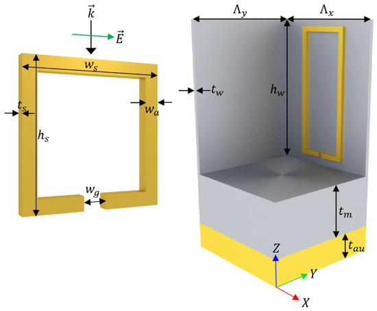
Figure 1.
The parameters used to define: (left) a split-ring resonator (SRR); and (right) unit cell are illustrated.
An individual SRR is defined by its height (), width (), thickness (), arm width (), and gap width (). Additionally, rotation of the SRR about the y-axis could also be considered, but is not shown in Figure 1. The unit cell is defined by its periodicity along X and Y directions ( and , respectively), wall height (), total wall thickness (), membrane thickness (), and thickness of the bottom gold layer (). The SRR material is gold, and the walls and membrane are silicon. Due to the bottom gold layer, and the absorption is simply . Dispersive optical constants for all the materials modeled were acquired using variable angle spectroscopic ellipsometry. The unit cell geometry is the same in each configuration, and is defined as = 2.30 m, m, m, m, m, and m.
3. Unit Cell Containing a Single VSRR
Although the unit cell geometry is relatively straight forward, SRRs demonstrate a rich absorption spectrum due to the several resonant modes they support [46,47,48]. Consider a unit cell containing a single VSRR, defined by parameters in Table 1, centered on a wall.

Table 1.
Dimensions of the VSRR. Units are in micrometers.
Inserted in an empty unit cell, a single VSRR produces a large absorption peak under a normally incident plane wave, polarized with the electric field parallel to the VSRR gap (Figure 2, top). Note that this VSRR is driven by both electric and magnetic fields of the illuminating plane wave, and this condition would not be possible in planar metasurfaces.
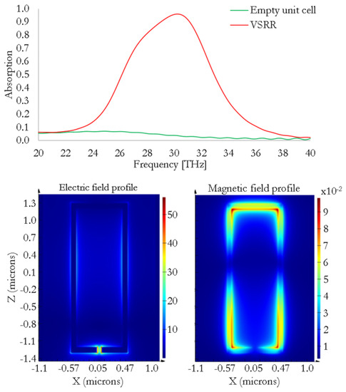
Figure 2.
(top) Spectral absorption; and (bottom) electric and magnetic field profiles (magnitudes) in V/m and A/m, respectively, are shown for a unit cell containing a single vertical split-ring resonator (VSRR).
The absorption peak () is located at 30.21 THz, and demonstrates a full-width at half-maximum (FWHM) of 6.96 THz. Figure 2 (bottom) shows the electric and magnetic field profiles (magnitudes) at the peak absorption frequency. The large absorption peak is being driven by the fundamental resonance of the VSRR, as indicated by the electric and magnetic field plots. The spectral absorption profile of the geometry is heavily dependent on the parameters illustrated in Figure 1. Many of these dependencies were explored as a part of this study but, for brevity, are not included here.
4. Unit Cell Containing a Single PSRR
In a similar manner, we now consider a unit cell containing a single PSRR. The PSRR dimensions are defined in Table 2.

Table 2.
Dimensions of the PSRR. Units are in micrometers.
Under normal incidence with the electric field polarized parallel to the PSRR gap, a plane wave excites a narrower absorption peak, as illustrated in Figure 3 (top). Note this PSRR is driven only by the electric field of the illuminating plane wave. The absorption peak () is located at the same spectral location of the single VSRR ( THz), and demonstrates a FWHM of THz. This result already shows the inherent advantages of using vertical metamaterials enabled by MPL, as the absorption bandwidth of the VSRR is more than double the one exhibited by the PSRR. The electric and magnetic field magnitudes are plotted at the resonance frequency in Figure 3 (bottom). Similar to the single VSRR, the fundamental resonance is driving the absorption for this geometry.
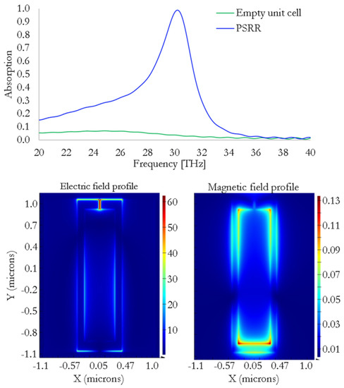
Figure 3.
(top) Spectral absorption; and (bottom) electric and magnetic field profiles in V/m and A/m, respectively, are shown for a unit cell containing a single planar split-ring resonator (PSRR).
5. Unit Cell Containing both a VSRR and PSRR
In a unit cell containing dual split-ring resonators (DSRR), the resonator gaps are, at first, intentionally placed near each other to strengthen intra-cell coupling. This condition is further ensured by the matching spectral locations of the peak absorption for the individual resonators. In the DSRR unit cell, the geometric dimensions of the unit cell, VSRR, and PSRR remain the same as in the previous geometries. The unit cell geometry, as well as the plot of spectral absorption for all geometries, are illustrated in Figure 4.
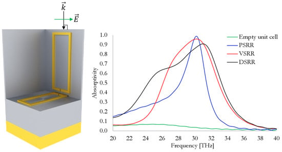
Figure 4.
(left) The dual split-ring resonator (DSRR) unit cell geometry is illustrated. (right) Spectral absorption is plotted for the case of an empty unit cell, a unit cell containing a single PSRR, a unit cell containing a single VSRR, and a unit cell containing both a VSRR and PSRR. Note the widening of the absorption band in the DSRR case.
As with the single resonators, the spectral response is heavily dependent on the geometric parameters of the unit cell and resonators. In the case when two resonators are coupled, however, the parameter space gains complexity from parameters that affect the intra-cell coupling (e.g., relative distance between the SRRs), which arises as a result of MPL’s capability to place SRRs on multiple surfaces within a single unit cell.
In this case, a normally incident plane wave produces an absorption curve characterized by a peak absorption () of the DSRR geometry located at THz, with a FWHM value of THz. The shift of the peak absorption and increased FWHM clearly indicate coupling between the SRRs. Furthermore, the DSRR response demonstrates that the absorption of the coupled resonators is not simply the cumulative sum of the individual resonators.
Similar to previous cases, electric and magnetic field profiles are shown in Figure 5. Specifically, Figure 5a,b shows the electric and magnetic field profile for the VSRR (similar to those shown in Figure 2), and Figure 5c,d shows the electric and magnetic field profile for the PSRR (similar to those shown in Figure 3). At peak absorption, the field profiles appear similar to those in the single SRR cases. When compared to the single SRR geometries, however, a significant decrease in peak field amplitude can be seen for both resonators. Additionally, the field profile near the point of highest concentration is noticeably altered due to the presence of the other resonator, further demonstrating the intra-cell coupling between them.
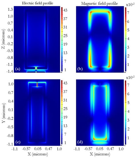
Figure 5.
The (a) electric and (b) magnetic field profiles of the VSRR in V/m and A/m, respectively, are plotted at peak absorption. The (c) electric and (d) magnetic field profiles of the PSRR in V/m and A/m, respectively, are plotted at peak absorption.
The performance of metamaterials as a function of the incidence angle of the source, , is also of great interest [3,39,49,50,51]. In Figure 6, spectral absorption is plotted as is swept from to . Polarization of the source is unchanged as the angle of incidence varies in the YZ plane.
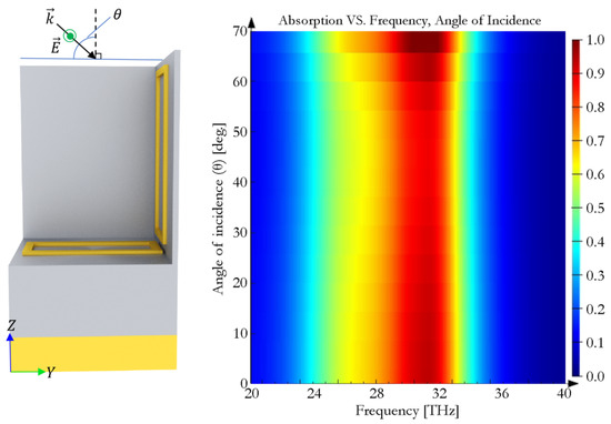
Figure 6.
(left) The DSRR unit cell geometry is shown, also illustrating variation of the angle of incidence, . (right) Spectral absorption is plotted as a function of frequency and angle of incidence.
Similar to individual resonators, the coupled resonators continue to demonstrate intolerance to changes in angle of incidence. As increases, the spectral location of the peak remains nearly unchanged; the lowest value of the absorption peak experienced over this range is .
6. Control of Intra-Cell Coupling
The ability to deactivate intra-cell coupling is of great interest, since this would increase both versatility of the DSRR geometry as well as control over the parameter space. Due to the high field concentration at the gaps in each resonator during peak absorption, three additional geometries were investigated, in which the VSRR and PSRR gaps were spatially separated. All three geometries and their optical responses are illustrated in Figure 7.
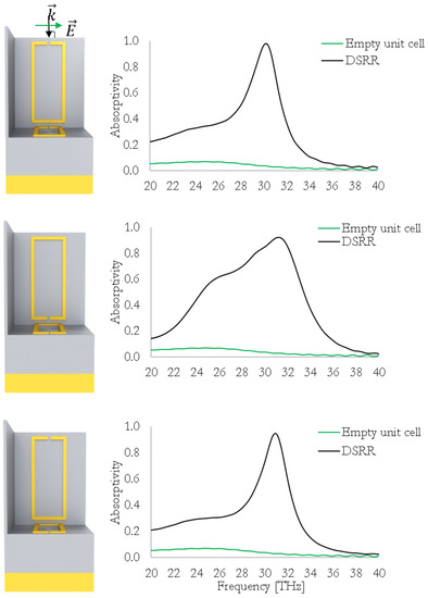
Figure 7.
The DSRR geometry is shown with: (top) a VSRR rotated 180; (middle) a PSRR rotated 180; and (bottom) both VSRR and PSRR rotated 180.
In the first case, the VSRR was rotated about the y-axis by 180, placing the SRR gap near the top of the walls; the PSRR orientation remained constant. In this configuration, the absorption profile strongly resembles that of the single PSRR unit cell, indicating that intra-cell coupling between the SRRs can be deactivated. This is due to interactions of the SRR with the unit cell membrane and gold layers as a function of VSRR orientation. For example, if the VSRR in Figure 1 (right) is placed in the rotated 180 orientation, a much weaker absorption peak is produced (). In the DSRR geometry, this enables the PSRR resonance to dominate the absorption response, yielding an absorption spectrum similar to Figure 3 (top).
In the second case, the VSRR orientation remained unchanged, and the PSRR was rotated about the z-axis by 180. In this configuration, the absorption profile resembles that of the DSRR geometry in Figure 4. Although the spatial distance between the SRRs is unchanged, the coupling is strongly based on the presence of strong absorption in the VSRR.
In the third case, the VSRR was rotated about the y-axis by 180, and the PSRR was rotated about the z-axis by 180. In this configuration, the absorption profile resembles that of the single PSRR unit cell, again indicating that intra-cell coupling between SRRs has been deactivated.
7. Discussion of Parameter Optimization
Maximum coupling between individual SRRs occurs when their peak absorption lies at the same frequency. For this reason, the parameter space of each single-SRR unit cell was investigated. This section provides a brief discussion of the sensitivity of each SRR to some of its geometric parameters. Since the spectral location of the peak PSRR absorption resonance was made to match that of the VSRR, the parameter space of the single-PSRR unit cell was more thoroughly explored, covering the , , and parameters. For brevity, only the height of the VSRR is discussed here. In both cases, the thickness of the SRRs were constrained by fabrication tolerances to m.
The height of the VSRR was swept from m to m. As the height of the VSRR increases, peak location moves towards lower frequencies (ranging from about 30 THz to about 40 THz), and the absorption peak broadens. Peak absorption amplitude remains >90%.
Values for the height of the PSRR were swept from m to m. As the height of the PSRR increases, the amplitude of the absorption peak increases and the FWHM broadens, shifting to lower frequencies (ranging from about 33 THz to about 40 THz).
Values for the width of the PSRR gap () were swept from m to m. At low gap width values, the absorption peak maintains an amplitude of , and shifts to lower frequencies (ranging from about 32 THz to about 34 THz). As the PSRR gap widens, the absorption peak decreases in amplitude, undergoing a decrease in FWHM.
Values for the width of the PSRR () were swept from m, to m. A very weak absorption peak is present even for low values of . As the PSRR widens, the absorption peak increases in amplitude, reaching a maximum, and then decreasing again for larger values of . The spectral location of the absorption peak shifts to lower frequencies as is increased.
8. Conclusions
Based on our investigation, it is evident that the use of multiple resonator geometries within a unit cell is key to enhancing and manipulating the spectral response of metamaterial devices. Unit cells containing a single VSRR, single PSRR, and multiple SRRs were examined to better understand inter-cell and intra-cell coupling. While inter-cell coupling is not discussed, intra-cell coupling between the orthogonal SRR components can be switched on and off based on the orientation of the vertical split-ring resonator.
The parameter space for a single SRR (not to mention two or more SRRs within a single unit cell) remains large and complex. Additional work is needed to gain deeper insight into parameter sensitivity for a single SRR, as well as the electromagnetic coupling between orthogonal or back-to-back resonators [24].
Author Contributions
All authors contributed to the design and implementation of the research, to the analysis of the results, and to the writing of the manuscript.
Funding
This research was supported by the Laboratory Directed Research and Development program at Sandia National Laboratories and by the Defense Advanced Research Projects Agency Defense Sciences Office (DSO) Program: DARPA/DSO EXTREME; Agreement No. HR0011726711.
Acknowledgments
This work was performed, in part, at the Center for Integrated Nanotechnologies, an Office of Science User Facility operated for the U.S. Department of Energy (DOE) Office of Science. Sandia National Laboratories is a multi-mission laboratory managed and operated by National Technology and Engineering Solutions of Sandia, LLC, a wholly owned subsidiary of Honeywell International, Inc., for the U.S. Department of Energy’s National Nuclear Security Administration under contract DE-NA0003525. This article describes objective technical results and analysis. Any subjective views or opinions that might be expressed in the article do not necessarily represent the views of the U.S. Department of Energy or the United States Government.
Conflicts of Interest
The authors declare no conflict of interest.
References
- Schurig, D.; Mock, J.J.; Justice, B.J.; Cummer, S.A.; Pendry, J.B.; Starr, A.F.; Smith, D.R. Metamaterial electromagnetic cloak at microwave frequencies. Science 2006, 314, 977–980. [Google Scholar] [CrossRef]
- Landy, N.I.; Sajuyigbe, S.; Mock, J.J.; Smith, D.R.; Padilla, W.J. Perfect metamaterial absorber. Phys. Rev. Lett. 2008, 100, 207402. [Google Scholar] [CrossRef]
- Tau, H.; Bingham, C.M.; Strikwerda, A.C.; Pilon, D.; Shrekenhamer, D.; Landy, N.I.; Fan, K.; Zhang, X.; Padilla, W.J.; Averitt, R.D. Highly flexible wide angle of incidence terahertz metamaterial absorber: Design, fabrication, and characterization. Phys. Rev. B 2008, 78, 1–4. [Google Scholar] [CrossRef]
- Liu, N.; Mesch, M.; Weiss, T.; Hentschel, M.; Giessen, H. Infrared perfect absorber and its application as plasmonic sensor. Nano Lett. 2010, 10, 2342–2348. [Google Scholar] [CrossRef]
- Hao, J.; Wang, J.; Liu, X.; Padilla, W.J.; Zhou, L.; Qui, M. High performance optical absorber based on a plasmonic metamaterial. Appl. Phys. Lett. 2010, 96, 251104. [Google Scholar] [CrossRef]
- Liu, X.; Starr, T.; Starr, A.F.; Padilla, W.J. Infrared spatial and frequency selective metamaterial with near-unity absorbance. Phys. Rev. Lett. 2010, 104, 207403. [Google Scholar] [CrossRef] [PubMed]
- Ding, F.; Ciu, Y.; Ge, X.; Jin, Y.; He, S. Ultra-broadband microwave metamaterial absorber. Appl. Phys. Lett. 2012, 100, 103506. [Google Scholar] [CrossRef]
- Luk, T.S.; Campione, S.; Kim, I.; Feng, S.; Jun, Y.C.; Liu, S.; Wright, J.B.; Brener, I.; Catrysse, P.B.; Fan, S.; Sinclair, M.B. Directional perfect absorption using deep subwavelength low-permittivity films. Phys. Rev. B 2014, 90, 085411. [Google Scholar] [CrossRef]
- Khuyen, B.X.; Tung, B.S.; Yoo, Y.J.; Kim, Y.J.; Lam, V.D.; Yang, J.G.; Lee, Y.P. Ultrathin metamaterial-based perfect absorbers for VHF and THz bands. Curr. Appl. Phys. 2016, 16, 1009–1014. [Google Scholar] [CrossRef]
- Faniayeu, I.; Mizeikis, V. Vertical split-ring resonator perfect absorber metamaterial for IR frequencies realized via femtosecond direct laser writing. Appl. Phys. Express 2017, 10, 062001. [Google Scholar] [CrossRef]
- Khuyen, B.X.; Tung, B.S.; Yoo, Y.J.; Kim, Y.J.; Kim, K.W.; Chen, L.-Y.; Lam, V.D.; Lee, Y. Miniaturization for ultrathin metamaterial perfect absorber in the VHF band. Sci. Rep. 2017, 7, 45151. [Google Scholar] [CrossRef]
- Zhang, Y.; Duan, J.; Zhang, B.; Zhang, W.; Wang, W. A flexible metamaterial absorber with four bands and two resonators. J. Alloys Compd. 2017, 705, 262–268. [Google Scholar] [CrossRef]
- Wang, W.; Wang, K.; Yang, Z.; Liu, J. Experimental demonstration of an ultra-fexible metamaterial absorber and its application in sensing. J. Phys. D Appl. Phys. 2017, 50, 135108. [Google Scholar] [CrossRef]
- Hasan, D.; Pitchappa, P.; Wang, J.; Wang, T.; Yang, B.; Ho, C.P.; Lee, C. Novel CMOS-compatible Mo–AlN–Mo platform for metamaterial-based Mid-IR absorber. ACS Photonics 2017, 4, 302–315. [Google Scholar] [CrossRef]
- Wang, W.; Yan, F.; Tan, S.; Zhou, H.; Hou, Y. Ultrasensitive terahertz metamaterial sensor based on vertical split-ring resonators. Photonics Res. 2017, 5, 571–577. [Google Scholar] [CrossRef]
- Pendry, J.B.; Holden, A.J.; Robbins, D.J.; Stewart, W.J. Magnetism from conductors and enhanced nonlinear phenomena. IEEE Trans. Microw. Theory Tech. 1999, 47, 2075–2084. [Google Scholar] [CrossRef]
- Katsarakis, N.; Konstantinidis, G.; Kostopoulos, A.; Penciu, R.S.; Gundogdu, T.F.; Kafesaki, M.; Economou, E.N.; Koschny, T.; Soukoulis, C.M. Magnetic response of split-ring resonators in the far-infrared frequency regime. Opt. Lett. 2005, 30, 1348–1350. [Google Scholar] [CrossRef]
- Fan, K.; Strikwerda, A.C.; Tao, H.; Zhang, X.; Averitt, R.D. Stand-up magnetic metamaterials at terahertz frequencies. Opt. Express 2011, 19, 12619–12627. [Google Scholar] [CrossRef][Green Version]
- Campione, S.; Mesa, F.; Capolino, F. Magnetoinductive waves and complex modes in two-dimensional periodic arrays of split ring resonators. IEEE Trans. Antennas Propag. 2013, 61, 3554–3563. [Google Scholar] [CrossRef]
- Monticone, F.; Alu, A. The quest for optical magnetism: From split-ring resonators to plasmonic nanoparticles and nanoclusters. J. Mater. Chem. C 2014, 2, 9059–9072. [Google Scholar] [CrossRef]
- Li, M.; Luk, K.-M.; Ge, L.; Zhang, K. Miniaturization of magnetoelectric dipole antenna by using metamaterial loading. IEEE Trans. Antennas Propag. 2016, 64, 4914–4918. [Google Scholar] [CrossRef]
- Tsai, W.-Y.; Chen, M.-K.; Wu, P.R.; Chen, Y.-H.; Chen, T.-Y.; Chen, J.-W.; Chu, C.H.; Wu, P.C.; Liao, C.Y.; Wu, H.; et al. Plasmonic metadevices by vertical split ring resonator. In 2016 International Conference on Optical MEMS and Nanophotonics (OMN); IEEE: Singapore, 2016. [Google Scholar]
- Lee, W.-H.; Chen, J.-W.; Chung, T.L.; Wu, P.C.; Liao, C.Y.; Tsai, D.P. VSRR for isotropic absorption and nanophotonic sensor. In JSAP-OSA Joint Symposia 2017; OSA: Fukuoka, Japan, 2017. [Google Scholar]
- Buckel, D.B.; Adomanis, B.M.; Sinclair, M.B.; Campione, S. Three-dimensional cut wire pair behavior and controllable bianisotropic response in vertically oriented meta-atoms. Opt. Express 2017, 25, 32198–32205. [Google Scholar] [CrossRef]
- Cubukcu, E.; Zhang, S.; Park, Y.-S.; Bartal, G.; Zhang, X. Split ring resonator sensors for infrared detection of single molecular monolayers. Appl. Phys. Lett. 2009, 95, 043113-3. [Google Scholar] [CrossRef]
- Xu, X.; Peng, B.; Li, D.; Zhang, J.; Wong, L.M.; Zhang, Q.; Wang, S.; Xiong, Q. Flexible visible-infrared metamaterials and their applications in highly sensitive chemical and biological sensing. Nano Lett. 2011, 11, 3232–3238. [Google Scholar] [CrossRef] [PubMed]
- Ishikawa, A.; Tanaka, T. Metamaterial absorbers for infrared detection of molecular self-assembled monolayers. Sci. Rep. 2015, 5, 12570. [Google Scholar] [CrossRef]
- Yue, W.; Wang, Z.; Whittaker, J.; Schedin, F.; Wu, Z.; Han, J. Resonance control of mid-infrared metamaterials using arrays of split-ring resonator pairs. Nanotechnology 2016, 27, 055303. [Google Scholar] [CrossRef][Green Version]
- Montoya, J.A.; Tian, Z.-B.; Krishna, S.; Padilla, W.J. Ultra-thin infrared metamaterial detector for multicolor imaging applications. Opt. Express 2017, 25, 23343–23355. [Google Scholar] [CrossRef] [PubMed]
- Chen, M.K.; Hsu, W.-L.; Wu, P.C.; Chen, J.-W.; Chen, T.-Y.; Chen, W.T.; Huang, Y.-W.; Liao, C.Y.; Sun, G.; Tsai, D.P. Vertical split-ring resonator based metasurface for light manipulation. In Frontiers in Optics; OSA: Rochester, NY, USA, 2016. [Google Scholar]
- Moritake, Y.; Tanaka, T. Controlling bi-anisotropy in infrared metamaterials using three-dimensional split-ring-resonators for purely magnetic resonance. Sci. Rep. 2017, 7, 6726. [Google Scholar] [CrossRef] [PubMed]
- Burckel, D.B.; Wendt, J.R.; Ten Eyck, G.A.; Ginn, J.C.; Ellis, A.R.; Brener, I.; Sinclair, M.B. Micrometer-scale cubic unit cell 3D metamaterial layers. Adv. Mater. 2010, 22, 5053–5057. [Google Scholar] [CrossRef]
- Burckel, D.B.; Resnick, P.J.; Finnegan, P.S.; Sinclair, M.B.; Davids, P.S. Micrometer-scale fabrication of complex three dimensional lattice + basis structures in silicon. Opt. Mater. Express 2015, 5, 2231–2239. [Google Scholar] [CrossRef]
- Burckel, D.B.; Campione, S.; Davids, P.S.; Sinclair, M.B. Three dimensional metafilms with dual channel unit cells. Appl. Phys. Lett. 2017, 110, 143107. [Google Scholar] [CrossRef]
- Liu, X.; Tyler, T.; Starr, T.; Starr, A.F.; Jokerst, N.M.; Padilla, W.J. Taming the blackbody with infrared metamaterials as selective thermal emitters. Phys. Rev. Lett. 2011, 107, 045901. [Google Scholar] [CrossRef]
- Ma, W.; Wen, Y.; Yu, X. Broadband metamaterial absorber at mid-infrared using multiplexed cross resonators. Opt. Express 2013, 21, 30724–30730. [Google Scholar] [CrossRef]
- Tao, H.; Bingham, C.M.; Pilon, D.; Fan, K.; Strikwerda, A.C.; Shrekenhamer, D.; Padilla, W.J.; Zhang, X.; Averitt, R.D. A dual band terahertz metamaterial absorber. J. Phys. D Appl. Phys. 2010, 43, 225102. [Google Scholar] [CrossRef]
- Huang, L.; Chowdhury, D.R.; Ramani, S.; Reiten, M.T.; Luo, S.-N.; Taylor, A.J.; Chen, H.-T. Experimental demonstration of terahertz metamaterial absorbers with a broad and flat high absorption band. Opt. Lett. 2012, 37, 154–156. [Google Scholar] [CrossRef]
- Tung, B.S.; Khuyen, B.X.; Kim, Y.J.; Lam, V.D.; Kim, K.W.; Lee, Y. Polarization-independent, wide-incident-angle and dual-band perfect absorption, based on near-field coupling in a symmetric metamaterial. Sci. Rep. 2017, 7, 11507. [Google Scholar] [CrossRef]
- Gay-Balmaz, P.; Martin, O.J.F. Electromagnetic resonances in individual and coupled split-ring resonators. J. Appl. Phys. 2002, 92, 2929–2936. [Google Scholar] [CrossRef]
- Marques, R.; Mesa, F.; Martel, J.; Medina, F. Comparative analysis of edge- and broadside- coupled split ring resonators for metamaterial design - theory and experiments. IEEE Trans. Antennas Propag. 2003, 51, 10. [Google Scholar] [CrossRef]
- Penciu, R.S.; Aydin, K.; Kafesaki, M.; Koschny, T.; Ozbay, E.; Economou, E.N.; Soukoulis, C.M. Multi-gap individual and coupled split-ring resonator structures. Opt. Express 2008, 16, 18131–18144. [Google Scholar] [CrossRef]
- CST Microwave Studio. Available online: http://www.cst.com (accessed on 29 May 2019).
- Lumerical FDTD Solution. Available online: http://www.lumerical.com/ (accessed on 29 May 2019).
- COMSOL Multiphysics. Available online: http://www.comsol.com (accessed on 29 May 2019).
- Linden, S.; Enkrich, C.; Wegener, M.; Zhou, J.; Koschny, T.; Soukoulis, C.M. Magnetic response of metamaterials at 100 Terahertz. Science 2004, 306, 1351–1353. [Google Scholar] [CrossRef]
- Rockstuhl, C.; Lederer, F.; Etrich, C.; Zentgraf, T.; Kuhl, J.; Giessen, H. On the reinterpretation of resonances in split-ring-resonators at normal incidence. Opt. Express 2006, 14, 8827–8835. [Google Scholar] [CrossRef] [PubMed]
- Giorgis, V.; Zilio, P.; Ruffato, G.; Massari, M.; Zacco, G.; Romanato, F. Resonance properties of thick plasmonic split ring resonators for sensing applications. Opt. Express 2014, 22, 26476–26486. [Google Scholar] [CrossRef]
- Feng, J.-Q.; Hu, W.-D.; Zhang, Q.-L.; Zong, H.; Huang, H.; Jin, Y.-T.; Wu, Y.-M.; Xu, Z.; Lv, X.; Si, L.-M. Polarization-independent and angle-insensitive metamaterial absorber using 90-degree-rotated split-ring resonators. Int. J. Antennas Propag. 2015, 240691. [Google Scholar] [CrossRef]
- Agrawal, A.; Singh, A.; Misra, M. A Multiband metamaterial absorber with concentric continuous rings resonator structure. Int. J. Adv. Microw. Technol. 2016, 1, 5–9. [Google Scholar]
- Nguyen, T.T.; Lim, S. Bandwidth-enhanced and wide-angle-of-incidence metamaterial absorber using a hybrid unit cell. Sci. Rep. 2017, 7, 14814. [Google Scholar] [CrossRef] [PubMed]
© 2019 by the authors. Licensee MDPI, Basel, Switzerland. This article is an open access article distributed under the terms and conditions of the Creative Commons Attribution (CC BY) license (http://creativecommons.org/licenses/by/4.0/).