Article

Design of a Laparoscopic Robot System Based on Spherical Magnetic Field

1
School of Mechanical Engineering & Automation, BeiHang University, Beijing 100083, China
2
School of Automation Science & Electrical Engineering, BeiHang University, Beijing 100083, China
*
Author to whom correspondence should be addressed.
Appl. Sci. 2019, 9(10), 2070; https://doi.org/10.3390/app9102070
Submission received: 12 March 2019 / Revised: 15 April 2019 / Accepted: 9 May 2019 / Published: 20 May 2019
(This article belongs to the Special Issue Next-Generation Surgical Robotics)

Abstract

:
In single incision laparoscopic surgery (SILS), because the laparoscope and other surgical instruments share the same incision, the interferences between them constrain the dexterity of surgical instruments and affect the field of views of the laparoscope. Inspired by the structure of the spherical motor and the driving method of an intraocular micro robot, a fully inserted laparoscopic robot system is proposed, which consists of an inner laparoscopic robot and external driving device. The position and orientation control of the inner laparoscopic robot are controlled by a magnetic field generated by the driving device outside the abdominal wall. The instrumental interferences can be alleviated and better visual feedback can be obtained by keeping the laparoscopic robot away from the surgical incision. To verify the feasibility of the proposed structure and explore its control method, a prototype system is designed and fabricated. The electromagnetism model and the mechanical model of the laparoscopic robot system are established. Finally, the translational, rotational, and deflection motion of the laparoscopic robot are demonstrated in practical experiment, and the accuracy of deflection motion of the laparoscopic robot is verified in open-loop condition.

1. Introduction

1.1. Background

The field of surgery has significantly advanced from traditional open surgery to minimally invasive surgery [1], and now there are new trends in this field aiming to meet the demands of surgeons and patients. One of these trends is the procedure known as single-incision laparoscopic surgery (SILS), which is attracting a great deal of attention worldwide because of the benefits that this method can offer. In SILS, medical instruments and the laparoscope are operated through a single incision in the derma of the patient’s abdominal cavity. Compared with traditional laparoscopic surgeries, SILS has several possible benefits including reduced operative complications, reduced postoperative pain, and better cosmetic results [2]. In SILS, however, because the surgical instruments share a common incision, the interferences between the laparoscope and other medical instruments constrain the dexterity of surgical instruments and affect the field of views of the laparoscope.
To solve these problems and take account clinical needs and technical requirements [3], fully inserted laparoscopes are designed. The interferences and visual affection can be alleviated by keeping the laparoscope away from the surgical incision. For a fully inserted laparoscope, the main challenge lies in the position and orientation control. Position and orientation here refer to the position and orientation of the robot relative to abdominal wall. In order to get clear and broader visual feedback in SILS, the position and orientation of the laparoscope should be controllable.

1.2. Related Works

Existing studies of the fully inserted laparoscope utilized in SILS have developed multiple methods of position control, including suturing, piercing, and attracting the laparoscope to the abdominal wall by an external permanent magnet (EPM).
Hu et al. developed two types of stick-shaped laparoscopic robots, which adopt DC servo motors combined with worm gear mechanisms to enable the pan and tilt motion of the camera [4,5]. During the surgery, these two laparoscopic robots are fixed by being sutured on the abdominal wall. Castro et al. proposed a wireless miniature anchored laparoscopic robot [6], the pan and tilt motion of its camera is manipulated by two inner motors. By applying a needle to pierce through the patient’s abdominal wall, the laparoscopic robot is fixed to the abdominal wall. However, both suturing or piercing methods have two significant shortcomings. One is the extra injures caused by suturing or piercing, the other is the limited reposition ability. Once these laparoscopic robots are fixed, it is difficult to reposition.
Different from the suturing and piercing methods, some research groups use EPMs to achieve the position control of the laparoscopic robot. Platt et al. proposed a fully-inserted modular wireless surgical robot. By changing the payload in its cylindrical housing, the robot can achieve multiple functions [7]. Through two magnetic caps at both ends of the robot, it can be magnetically attached to the inside of the abdominal wall and achieve pan motion by an EPM handle. Valdastri et al. designed a wireless laparoscopic camera system which embeds two internal permanent magnets (IPMs) in a capsule-shaped housing [8], two EPMs are adopted to achieve the pan and shift control of the laparoscopic robot, and the rotation of the camera along its axis is achieved by an inner motor. A modified design is proposed in [9]. Compared with these methods of position control, the use of EMPs are more flexible.
As for orientation control, most of the existing laparoscopic robots use micro motors and gear mechanisms to achieve the tilt motion of the inner camera, and adopt other mechanisms (suturing, piercing, EMP, etc.) to achieve the position control of the robot. However, the inner motor along with a relevant mechanism will complicate the structure, enlarge the dimension, and increase the energy consumption of the laparoscopic robot.
To address the above problems, this paper proposed an innovative configuration of laparoscopic robot, which adopts external magnetic field to achieve position and orientation control of the laparoscopic robot. Therefore, the inner motor-based motion mechanism can be removed, and the laparoscopic robot will have simpler structure, less energy consumption, and more room for other sensors.

1.3. The Present Work

Inspired by the research of spherical motor [10,11], as well as the driving method of an intraocular micro robot OctoMag [12], a laparoscopic robot system is designed in this paper. Both OctoMag and the structure proposed in this paper use multiply electromagnets to generate controllable magnetic field to control the position and of the robot. However, the OctoMag is designed for microrobots used in retinal procedures, therefore, gravity compensation of the robot is relatively easy to achieve due to the liquid work environment and the light weight of the robot. However, for the structure proposed in this paper, electromagnets need to provide enough force to compensate the gravity of the laparoscopic robot, which is the prerequisite for position and orientation control of the robot.
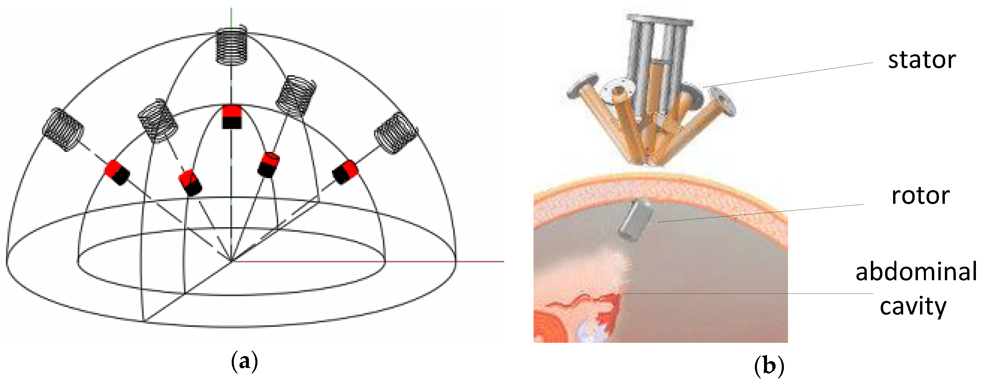
As shown in Figure 1, the system consists of an external driving device (i.e., the stator) and an inner laparoscopic robot (i.e., the rotor). The stator consists of five electromagnets. The rotor is a capsule-shaped cylinder, whose hemispherical dome is installed with IPMs. The distribution of electromagnets and IPMs are shown in Figure 2a.
As shown in Figure 2b, under the action of the external magnetic field, the stator can keep the rotor away from the incision and then make room for other surgical instruments in SILS. Thus, the interferences between rotor and other surgical instruments can be avoided. Additionally, the stator can provide position and orientation control of the rotor to achieve adjustable field of views. Since the driving system is separated from the laparoscopic robot, the laparoscopic robot has a simpler structure, less energy consumption, and smaller size.
In this paper, only the cylindrical shell and the hemispherical dome with IPMs of the rotor are fabricated. In order to test the carrying capacity of our design, the IMU unit, wireless unit, camera unit, and the power unit are replaced by a counterweight in practical experiments.
In the following part, the structure and control principle of the robot system will be introduced in detail.

2. Control Principle of the Laparoscopic Robot System

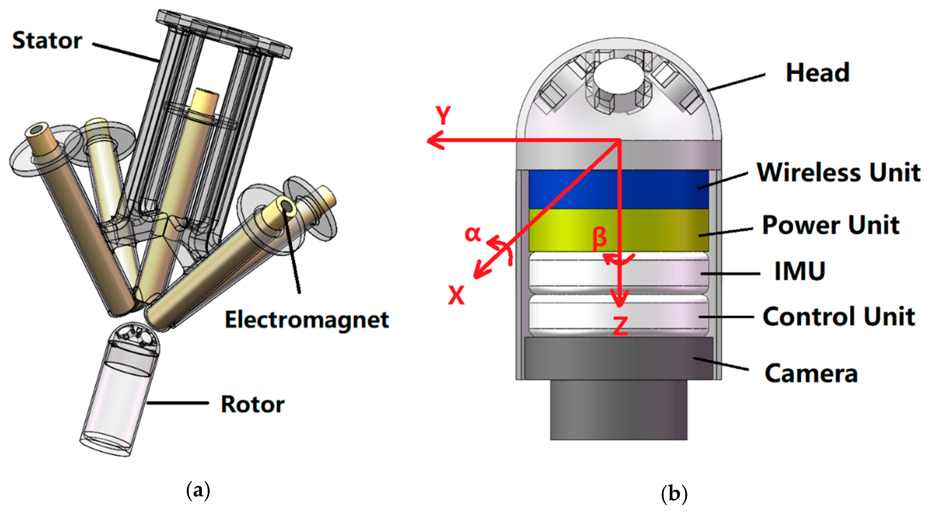
In our design, the control of the rotor consists of two parts: (1) the position control and (2) the orientation control. As shown in Figure 3, the position control involves the shift along the x and y axes, the orientation control involves the deflection perpendicular to the z axis (i.e., the nutation angle α ), and the rotation along the z axis (i.e., the precession angle β ).
The position control of the rotor is achieved by repositioning of the stator. If the position of the stator changes, the position of the magnetic field created by the stator will be changed, and the rotor will follow the movement of the stator under the magnetic force. The orientation of the rotor is determined by both orientation and input electric currents of the stator. By changing these parameters, the intensity and orientation of the magnetic field will be changed, and so are the magnetic force and torque acting upon the IPMs of the rotor. Therefore, the orientation of the rotor can be controlled. To simplify the control model, the rotation motion of the rotor is achieved by rotating the stator, and the deflection motion of the rotor is controlled by changing the input electric currents.
In order to achieve the deflection control of the rotor, the relationship between the combination of five input electric currents I ( I 1 I 2 I 3 I 4 I 5 ) of the stator and the deflection angle α ( I ) of the rotor need to be established. For that purpose, the magnetic flux density B i ( x , y , z , S m , R c , Φ c , I i ) (i from 1–5) created by every coil of the stator and the magnetic moment M j ( k , S m ) (j from 1–5) of every IPM in the rotor should be determined at first, where B i is concerned with the location p ( x , y , z ) , the diameter of wires R c , the dimension of magnetic iron core S m , the numbers of coil turns Φ c , and the electric current I i through every coil., whereas the magnetic moment M j is determined by the material k and the dimension of IPMs S m .
By mechanical design and parameter selection, the expression of the magnetic flux density B i of every coil, as well as the magnetic moment M j of every IPM can be obtained. Subsequently, the magnetic force and torque of coil to IPM can be solved. By superimposing the force and torque of every electromagnet to all five IPMs, the relationship between input current I ( I 1 I 2 I 3 I 4 I 5 ) and the force F ( I , P ) and torque T ( I , P ) from the stator to the rotor can be determined, and both of them are determined by the input current I and the orientation of the rotor P . Then, by analysing the force and torque acting on the rotor, the relationship between the input current I and the deflection angle of the rotor α ( I ) in the balanced condition can be determined.
In the following part, the process of mechanical design and parameter selection will be introduced in detail.

3. Structural Design of Laparoscopic Robot System

3.1. Main Structure of the Laparoscopic Robot System

As shown in Figure 2a, the laparoscopic robot system consists of a stator and a rotor. The stator consists of five electromagnets, while the rotor consists of five IPMs. These electromagnets and IPMs are distributed on concentric hemispheres. For the rotor, one of its IPMs are distributed on the “north” side of sphere, the rest of the four IPMs are distributed at 45 ° north latitude of the sphere, and the latitude difference between adjacent IPMs is 90 ° . The distribution of the electromagnets in the stator is similar to that of the IPMs but in a different concentric hemisphere.
Electromagnets are adopted for the stator rather than permanent magnets because the combination of electromagnets is more flexible in controlling magnetic fields. Additionally, electromagnets can create the desired magnetic field by changing the input currents of electromagnets, which can simplify the position and orientation control of the stator.
In theory, the configuration of three or four electromagnets can achieve the position and orientation control of the stator, and the symmetric configuration of four electromagnets are more stable in the deflection control of the robot than the configuration of three. However, these two configurations will also lead to the strong coupling between gravity compensation and orientation control of the rotor and, therefore, limit the driving capacity to the stator. Thus, a vertically-distributed electromagnet is added in the configuration of four electromagnets to achieve the gravity compensation of the stator, which can weaken the coupling between gravity compensation and deflection control, and then achieve better controlability.

3.2. Design of the Rotor

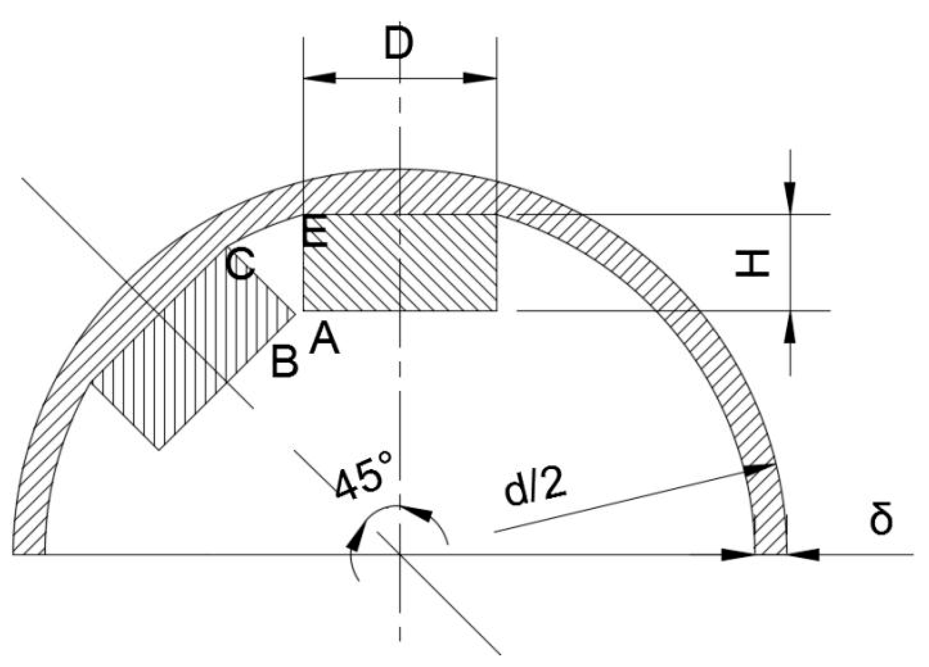
In SILS, the radius of the surgical incision is generally 25 mm to 30 mm [13]. To ensure that the laparoscopic robot can meet the requirements of most SILSs, the diameter of the laparoscopic robot is preliminarily selected as 24 mm (shown in Figure 4). In the design of the rotor, cylindrical magnets (NdFeB35) are selected. To avoid interferences between IPMs, we have:
( d 2 δ ) s i n ( π 8 a r c s i n D d 2 δ ) s i n π 4 H s i n 3 π 8
where d represents the external diameter of the rotor’s hemispherical end and the thickness of hemispherical shell δ is 1 mm. D indicates the diameter of the IPM. And H is the height of the IPM.
According to Equation (1) and available types of IPMs, the parameters of the IPMs are selected as D = 6 mm and H = 3 mm, with residual magnetization as 1.21 Tesla.

3.3. Design of the Stator

To ensure the accuracy of the following linear modeling of magnetic flux density B i , it is necessary to magnetize the iron cores along the radial direction as much as possible when determining the dimension S m of the inserted iron cores.
According to [14], the ferromagnet can be magnetize linearly when the external magnetic field is controlled within a certain range, which can be expressed as:
M = χ H i
where M represents the magnetization intensity of the ferromagnet. χ is the magnetic susceptibility. H i is the internal magnetic field of the ferromagnet.
In Equation (2), H i is composed of external magnetic field H and internal demagnetizing field H d :
H i = H + H d
The intensity of demagnetizing field H d is concerned with the demagnetization tensor N , which can be expressed as:
H d = N M
N is related to the shape of the ferromagnet. For ferromagnets with symmetric axes, when the magnetic coordinate is aligned with the principal axis of the ferromagnet, N is a diagonal matrix, and the diagonal line of which consists of demagnetization factor n x , n y and n z ( n x , n y , and n z , respectively, indicate the demagnetization factor along x, y, and z axis). By combining Equations (3) and (4), one can obtain:
M = χ a H
where:
χ a = d i a g ( χ 1 + n x χ , χ 1 + n y χ , χ 1 + n z χ )
According to [14], we have:
n x + n y + n y = 1
The demagnetization factors n x , n y , and n z only concern with the shape of the ferromagnet.
For a cylindrical ferromagnet, the greater the ratio of the length to the diameter, the closer these parameters approach the following conditions:
n x = n y = 1 2 ,   n z = 0
Since the magnetic susceptibility χ of a ferromagnet is very large, according to Equations (5)–(8), we can tell that the greater the ratio of the length to the diameter, the greater the axial component and the smaller the radial component of magnetization intensity M . Accordingly, the ferrite cores are more inclined to be magnetized along the radial direction.
According to [15], the relationship between the ratio of the length to the diameter and the demagnetization coefficient n z is shown in Table 1.
According to Table 1, when the ratio of length to diameter exceeds 10, n z is less than 0.02, and the axial component of χ a is more than 20 times larger than its radial component. In this condition, the cylindrical ferromagnet is considered to be axially magnetized. Therefore, the dimension of these ferrite cores is preliminarily selected as diameter = 6 mm and length = 100 mm.
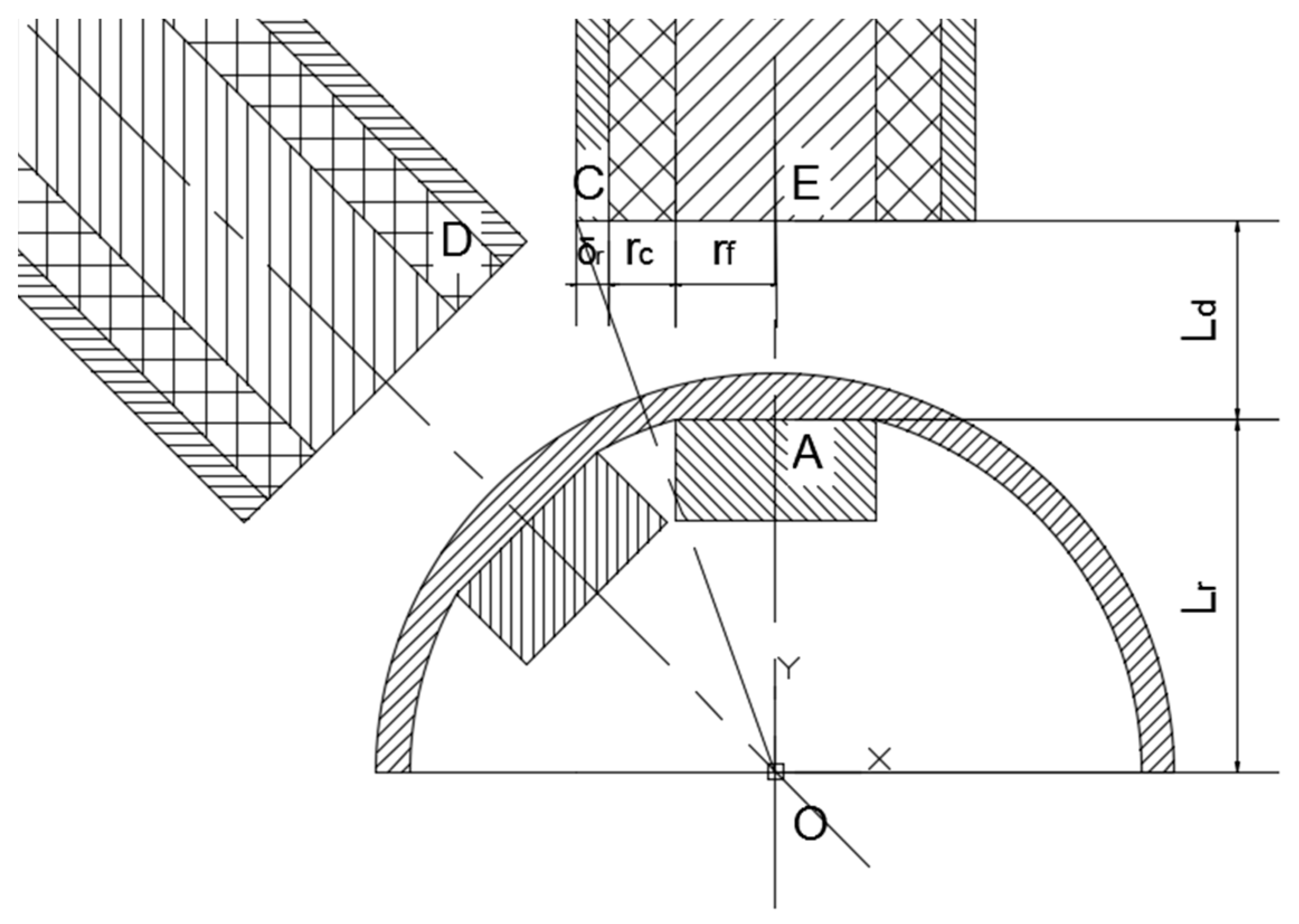
After the size of the ferrite core is determined, the electric current I i through every coil, the turns of electromagnets Φ c , as well as the distance between the rotor and the stator ( L b in Figure 5) can be subsequently determined. To obtain a greater magnetic flux intensity, more coil turns should be adopted, however, since the electromagnets of the stator are tilting to a same point (the point O shown in Figure 5), there is a relationship between the distance of the stator and the rotor and the greatest amount of coil turns without interference between the electromagnets of the stator.
In Figure 5, L d is the distance between the IPMs and the coil. L r represent the distance between the upper surface of IPMs and the sphere center, r c is the thickness of the coil δ r is the thickness of shell and r f is the radius of the magnetic iron core.
To avoid the interference among coils, we have:
t a n π 8 r c + r f + δ r L r + L d
where L r is 10.58 mm, r f is 3 mm and δ r is 1 mm. Thus, one can obtain:
r c 0.38 + 0.414 L d
Considering the gaps among wires, the cross section of wires is equivalent to a square, thereby the maximum turns of coils can be expressed as:
Φ c = 100 r × E ( 0.38 + 0.414 L d r )
In the above formula, r represents the radius of the wire and E is the integral function.
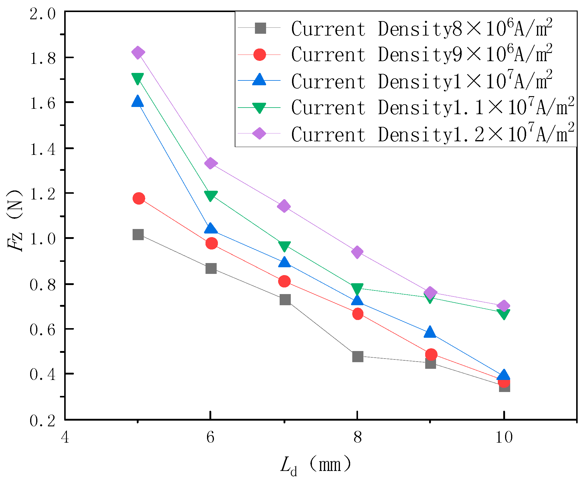
In this paper, the diameter of wires is selected as 0.5 mm. To prevent overheating, the electric current I i through coils should be within 2–3 A (corresponds to 8 ~ 12 × 10 6   A / m 2 in current density). To further determine a proper distance between the stator and the rotor, the relationship between the distance and the magnetic force between the central vertical coil and the rotor in different electric current densities is obtained by the finite-element simulation software ANSYS Maxwell 1.6 (ANSYS Inc., Pittsburgh, PA, USA). In this simulation, the turns of coil Φ c are determined by Equation (11), and the central axis of the rotor is kept vertically. The simulation result is shown in Figure 6.
According to the simulation result, the distance and the electric current I i through the wires can be preliminarily determined. On the one hand, the mass of the stator is approximately 50 g, therefore, there needs to be at least a force of 0.5 N to compensate for gravity. Considering the deflection movement of the rotor, as well as the errors, result from fabrication and assembly, the actual force need to be more than 0.5 N. On the other hand, to avoid the overheating of the coil, lower electric current is better.
In summary, the distance L d is selected as 6 mm, the electric current I i is selected as 8 × 10 6   A / m 2 , and the correspond magnetic force between the stator and the rotor is approximately 0.8 N.
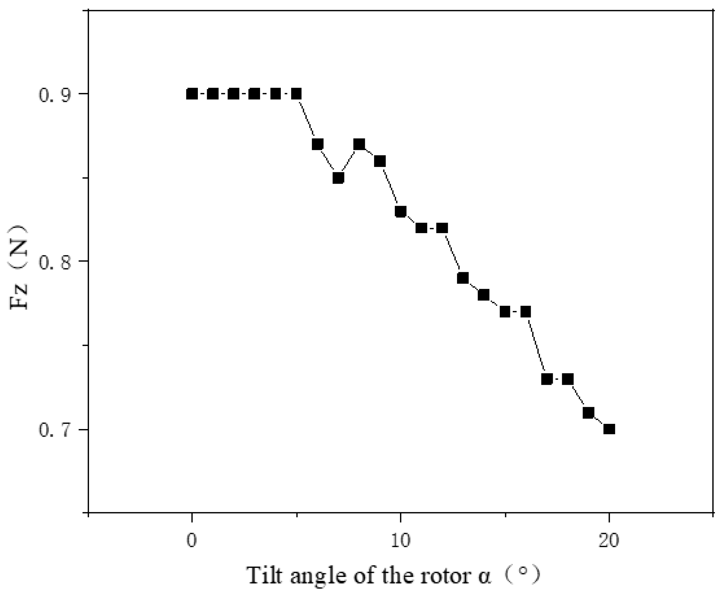
To verify the validity of these selected parameters, the magnetic force between the stator (including all five electromagnets) and the rotor in different deflection angles is obtained by finite-element simulation.
As shown in Figure 7, when the deflection angle α is beyond 20 degrees, the magnetic force between the stator and the rotor is still over 0.6 N. Thus, the parameters selected before are valid.

4. Mathematic Modeling

To realize real-time control of the rotor, it is necessary to establish the force and torque model between the stator and the rotor. All the magnetic material can be denoted by the magnetic moment M , whose unit is A · m 2 . For the permanent magnet (PM), its magnetic moment M is constant. For soft magnetic material, its magnetic moment M is determined by the intensity of external magnetic field.
For PM, the torque acting upon it can be expressed as:
T = M × B
The force acting on PM can be expressed as:
F = ( M · ) B
In Equations (12) and (13), B represents the magnetic flux intensity at the position of PM.
Since there is no electric current in the area of PM, according to the Maxwell equation, we have:
× B = 0
According to Equations (13) and (14), F can be expressed as:
F = [ B x   B y   B z ] T M
In order to obtain the force and torque acting on the rotor, the magnetic flux intensity B produced by the stator and the magnetic moment M of the rotor needs to be solved first.

4.1. The Magnetic Flux Intensity B Produced by Stator

To solve the comprehensive magnetic flux intensity B produced by multiple electromagnets, the magnetic flux intensity created by every single coil B i should be determined first, and then these magnetic fields are superimposed together.

4.1.1. The Magnetic Flux Intensity B Produced by Single Electromagnet

The magnetic field produced by every electromagnet consists of two parts. One part is created by electrified coils, the other is produced by magnetized ferrite cores. On the one hand, since the magnetoconductivity of ferrite cores is very large, it can be assumed that the magnetic field produced by the ferrite cores is much larger than that of the coils, and the latter one can be ignored. On the other hand, because the ferrite cores are cylindrical and their ratio of height to diameter is very large, the ferrite cores can be considered magnetized uniformly.
According to the laws of physics, we have:
M q = χ m H
where M q is the magnetization intensity of the ferrite core, χ m is the magnetic susceptibility of the ferrite core, and H is the magnetic field intensity where the iron cores are located.
According to the Ampere circuit law, one can obtain:
L H = n I L
where n represents the turns of coil on unit length. L indicates the total length of coil. I indicates the electric current through coil.
By combining Equations (16) and (17), one can obtain:
M q = χ m n I
As the ferrite cores are magnetized uniformly, the magnetizing current only exists in the surface of them [16], those magnetized iron cores can be seen as concentrated electromagnets distributed in the surface of the magnetized iron cores, and their surface current density can be expressed as:
i = M q × n n
where n n is the normal vector of the surface of iron core.
According to [16], when the center of magnetic dipole is taken as the coordinate origin O , the magnetic vector potential created by single magnetic dipole at an arbitrary point P in space is:
A p = μ 0 a 2 I   s i n   θ d 4 r 2
In the above equation, μ 0 indicates the magnetoconductivity in vacuum, a is the diameter of the magnetic dipole, I d represents the electric current through the magnetic dipole, r indicates the vector length from the coordinate origin to point P , and θ indicates the angle between vector O P and normal vector of magnetic dipole.
Therefore, the magnetic vector potential produced by a single iron core is:
A = l L + l μ 0 a 2 i   s i n   θ 4 r 2 d h
where l is the distance between the target point and coil. L is the height of coil. According to [16], we have:
B = × A
By combining Equations (18)–(22), one can get the relationship between magnetic flux density B created by every single coil to the electric current I through it:
B = B u ( χ m ) I
where I is the electric current through electromagnets, B u ( χ m ) is the magnetic flux intensity by unit electric current, which concerns the unknown variable χ m .
By fitting the unknown variables in Equation (23) with the exact solution obtained by finite element simulation, the approximate solution of X m can be obtained [12], therefore, the magnetic flux density of every coil B i can be expressed by the input electric current I i .

4.1.2. Superposition of Magnetic Flux Intensity B Produced by Multiple Electromagnets

In order to superimpose the magnetic flux intensity B produced by multiple electromagnets B i , different coordinates need to be established, including five coil coordinates C S i , (i = 1, 2 … 5), a global coordinate C S 0 , as well as a rotor coordinate C S r . These coil coordinates are used to represent magnetic fields B i created by every single coil. These rotor coordinates are used to represent the magnetic moment of every IPM M j in the laparoscopic robot. The global coordinate is used to unify M of every coil and B of every IPM into the same coordinate.
To solve the magnetic field created by every single coil, the position in global coordinate C S 0 needs to be transferred into coil coordinate C S i , the transformation relation can be expressed as:
P i = R i P + T i ;   ( i = 1 ,   2 ,   3 ,   4   o r   5 )
where P = ( x , y , z ) represents the position P in global coordinate C S 0 . P i = ( x i , y i , z i ) is the same position P in coil coordinate C S i . R i and T i are rotation matrix and translation matrix from coil coordinate C S i to global coordinate C S 0 .
After obtaining the magnetic flux intensity produced by all the electromagnets, the total magnetic flux intensity can be obtained by superposing them:
B ( x , y , z ) = i = 1 5 R i T B i ( x i , y i , z i )
According to [16], if the intensity of magnetic field changes within a certain range, the magnetic field intensity created by soft magnetic material is proportional to the intensity of the external magnetic field. Therefore, Equation (25) can be expressed as:
B ( x , y , z ) = i = 1 5 R i T B i u ( x i , y i , z i ) I i
where I i is the electric current through coil i , and B i u is the magnetic flux intensity created by electromagnet i by unit electric current.
In an actual situation, the magnetization of the iron core of a coil will be affected by other electromagnets. Thus, the comprehensive magnetic flux intensity of all five electromagnets is not the linear superposition of that of every coil. Since the relative position among five coils remains unchanged, the actual magnetic flux intensity of all five electromagnets can be expressed as:
B ( x , y , z ) = i = 1 5 K i R i T B i ( x i , y i , z i ) I i
In above formula, K i is the coefficient of correction of magnetic flux intensity of every coil, which can be fitted by the result of finite-element simulation.

4.2. Magnetc Moment of Rotor

In order to solve the comprehensive force F and torque T acting on the rotor, the force and torque acting on every single IPM should be obtained and then superposed together.
In the rotor coordinate C S i , position and orientation of IPM j can be expressed by T j r and R j r respectively (j = 1, 2, 3, 4, or 5). As mentioned before, the size of magnetic moment M of IPM is constant, and the direction of which is determined by orientation of every IPM. Thus, the magnetic moment of IPM j in rotor coordinate C S r M j r can be expressed as:
M j r = m j · r j
where m j denotes the size of magnetic moment of IPM j , and r j represents its direction.
In Equation (27), the size of magnetic moment of IPM j can be expressed as:
m j = k j B r π D j 2 L j 4 μ 0
where B r is the remanence of every IPM, D j and L j respectively denote the diameter and length of every IPM. Similar to the coefficient of correction K i , coefficient of correction k j are utilized to eliminate the effect between different IPMs, which can be obtained by finite-element simulation.
The direction of magnetic moment r j can be solve by the following equation:
r j = R j r ( 0 , 0 , 1 ) T
The transformation equation from the rotor coordinate to the global coordinate can be expressed as:
P = R r P r + T r
In the above equation, R r is the rotation matrix from global coordinate C S 0 to the rotor coordinate C S r , and T r represents the translation matrix from global coordinate C S 0 to the rotor coordinate C S i . Combining Equations (24) and (30), one can obtain:
P i = R i ( R r P r + T r ) + T i
and:
M j i = R j R r M j r
Hence, M and B can be expressed in the same coordinate. M j i is the magnetic moment of the IPM j in coil coordinate C S i , and M j r is the magnetic moment of permanent j in its rotor coordinate.

4.3. Solution of Force and Torque

In order to achieve the position and orientation control, as well as the gravity compensation of the rotor, both force and torque acting on the rotor need to be solved. During the solving process, the magnetic forces of the stator to different IPMs of the rotor are not necessarily collinear. Thus, the torque acting on the rotor consists of two parts. One part is created by direction differences of magnetic flux intensity and the magnetic moment of the IPMs. The other part is produced because the magnetic force upon different IPMs are not collinear.
When calculating the second part of the torque, the computation process can be simplified by setting the rotation center at the hemispherical sphere center of the rotor (i.e., the coordinate origin of the global coordinate). Then, the force and torque of a single coil acting on rotor can be expressed as:
F i u = j = 1 5 [ B i u x B i u y B i u z ] T M j i
T i u = j = 1 5 [ M j i × B i u + L j × [ B i u x , B i u y , B i u z ] T M j i ]
Among the above expressions, L j is the arm of the force of IPM j to the hemispherical center of the rotor, M j i is the magnetic moment of IPM j in coil coordinate C S i . F i u is the magnetic force of coil i to the rotor by unit electric current, and T i u is the magnetic torque of coil i to the rotor by unit electric current.
The force and torque acting on the rotor can be expressed as:
F = j = 1 5 R j T F j u I j
T = j = 1 5 R j T T j u I j

4.4. Statics Analysis

The force acting on the rotor can be divided into four parts: the magnetic force F m from the stator, the gravity m g , the support force F n , as well as the friction force f from the abdominal wall.
When the position and gesture of the rotor change slowly, every moment of the whole moving process can be considered as a quasi-stationary state. According to Newton’s law of motion, we have:
F m F n f m g = 0
As mentioned in the control principle part, the position of the rotor is controlled by the orientation of the stator. The posture control of the rotor consists of two DOFs, the rotation along the precession angle α , and the deflection along the nutation angle β .
To simplify the control model and reduce computation, the rotation of the rotor is realized by the self-rotation of the stator. The deflection control of the rotor is realized by changing the electric current of electromagnets.
To achieve gravity compensation of the rotor we have:
| F z | | m g |
where F z is the attractive force from the stator to the rotor along the vertical axis Z .
To achieve the deflection control of the rotor, the input electric current of the stator need to be change to make the status of the controlling magnetic field corresponds to the target position of the rotor. The related status of the controlling magnetic field can be obtained by combining Equation (32) and the following equation set:
{ T x = m g l T y = 0
In Equation (40), T x is the magnetic torque upon the rotor along the direction of axis x, and T y is the magnetic torque upon the rotor along the direction of axis y. l is the force arm of gravity.
Combining Equations (36), (37), (39), and (40), the relationship between the combination of input electric current I ( I 1 I 2 I 3 I 4 I 5 ) and the deflection angle α ( I ) can be obtained.
In the orientation control of the rotor, because there are five input electric currents, except a constraint condition provided by the gravity compensation of the rotor, there are multiple solutions. Therefore, in the actual orientation control of the rotor, some input electric current need to be selected previously.

5. Verification Experiments

To verify the control principle of the laparoscopic robot system, as well as the accuracy of the previous modeling, a verification experiment of translational, rotational, and deflectional motion of the rotor is carried out. For that purpose, an experimental platform is built.

5.1. The Structure of the Experimantal Platform

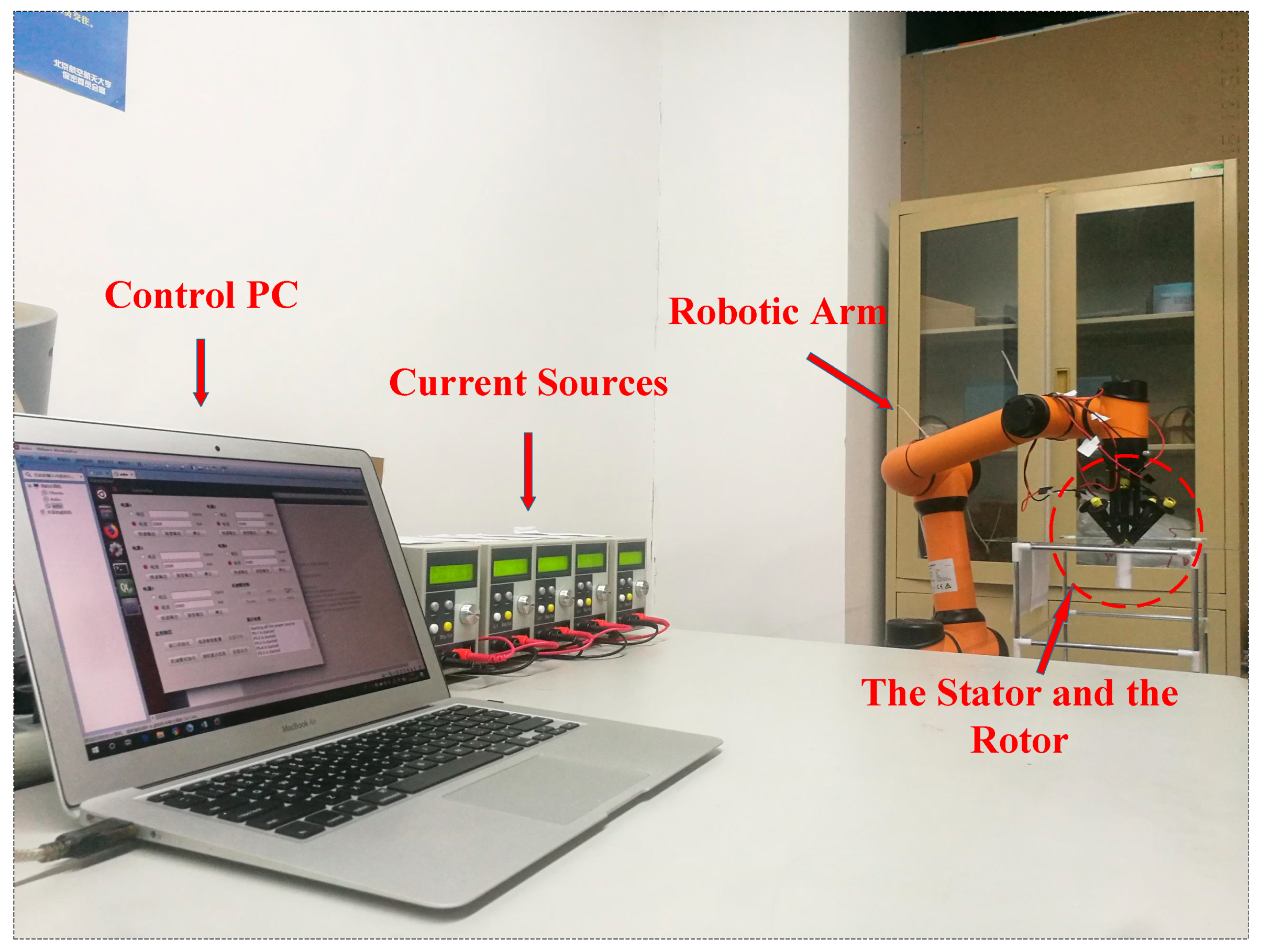
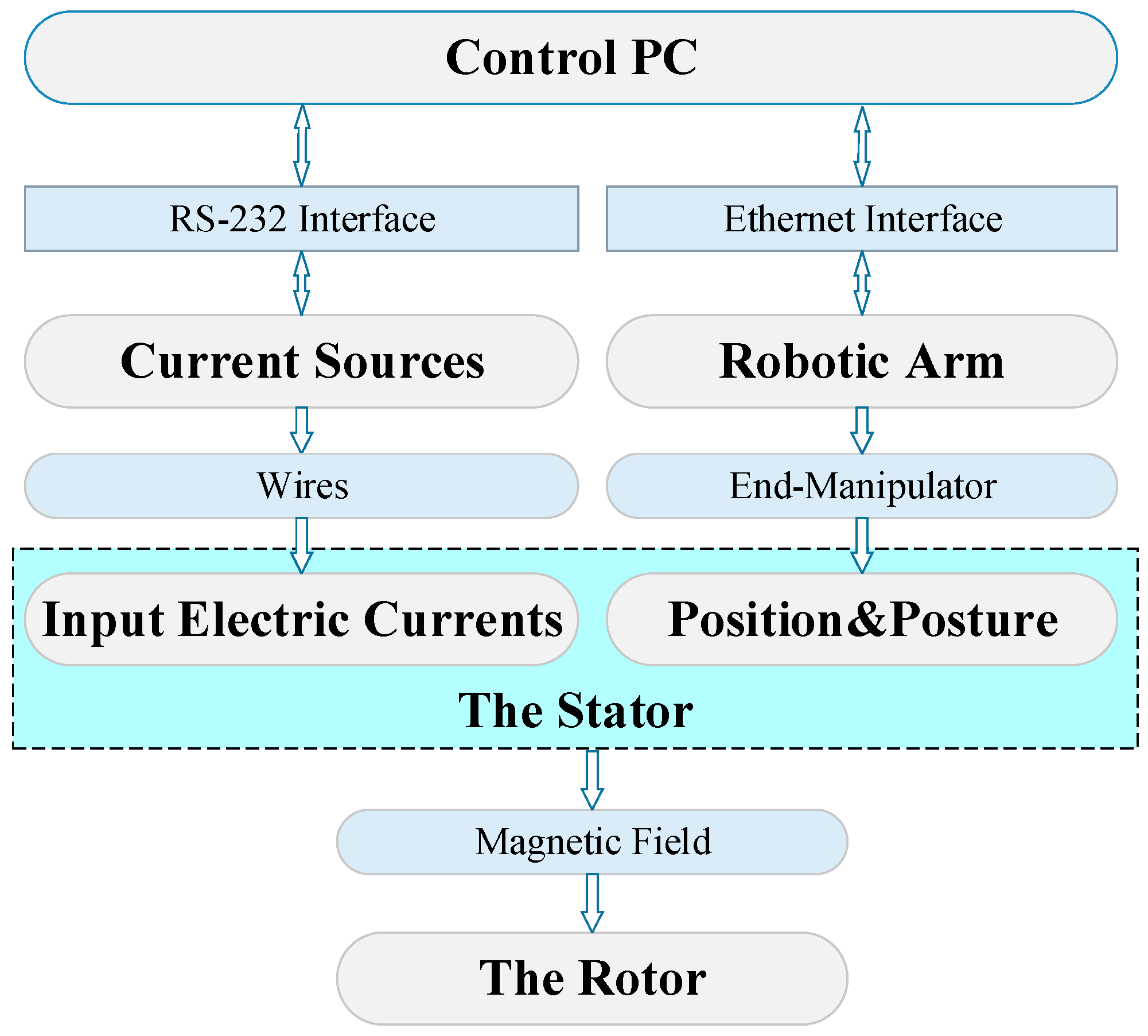
As shown in Figure 8, the experimental platform consists of a control PC, five current sources, a robotic arm, the stator, as well as the rotor. The logical structure of the experimental platform is shown in Figure 9.
In this experimental platform, both the current sources and the robotic arm are connected and controlled by a control PC. These current sources are connected to five electromagnets to supply electric currents for the stator. Through an RS-232 interface, the output of these current sources can be controlled by the control PC. Therefore, the input currents of the stator can be controlled.
For the robotic arm, it is connected to the control PC through an Ethernet interface. Through a control program, the position and orientation of the robotic arm can be controlled by the control PC, as can the position and orientation of the stator fixed at the end-manipulator of the robotic arm. Under the action of the magnetic field created by the stator, the translational, the rotational, as well as the deflection motion of the rotor can be achieved.

5.2. Translational and Rotational Motion of the Rotor

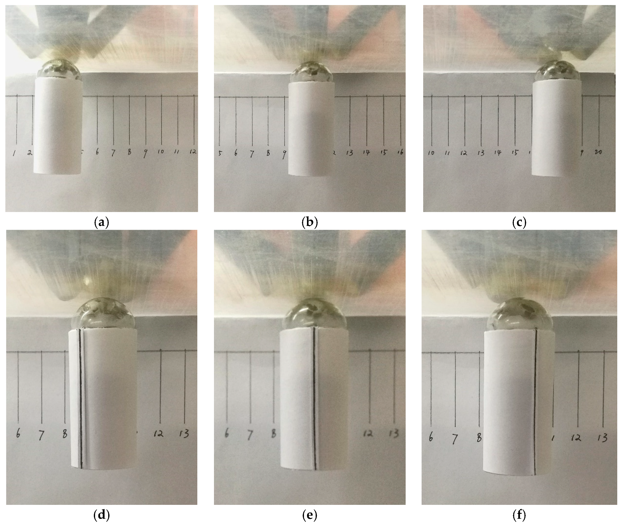
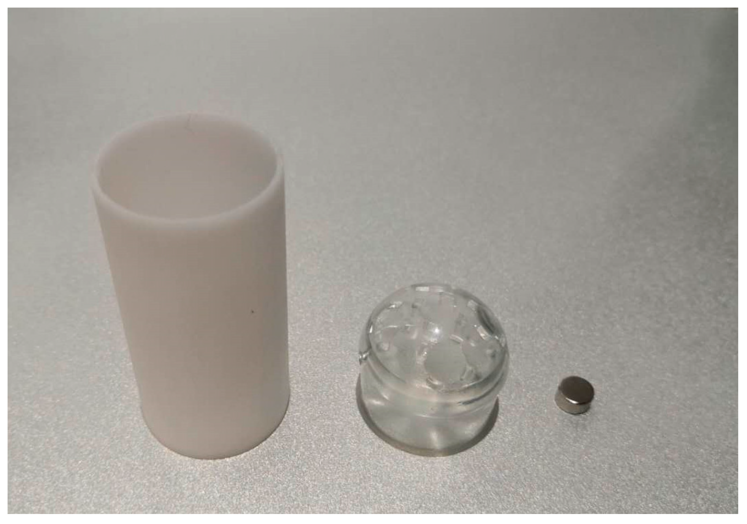
To verify the translational and rotational motion of the stator, a transparent acrylic plate is placed between the stator and the rotor for distance control. Based on the control principle mentioned before, under the magnetic force and torque, the translational and rotational motion of the rotor can be achieved by the corresponding motion of the stator. Figure 10 shows the translational and rotational motion of the rotor. Figure 11 shows the structure of the rotor utilized in experiment.

5.3. Deflection Motion of the Rotor

To verify the deflection control of the rotor, the actual deflection angle α ( I ) under certain input electric currents I ( I 1 I 2 I 3 I 4 I 5 ) needs to be compared with the expected angle. However, it is difficult to obtain the accurate deflection angle during the experiment. Thus, we could compare the actual input electric currents I and its theory value calculated from the established model instead. Figure 12 shows the experimental process, and the experimental principle is given in the following part.

5.4. Measurement of Deflection Angle

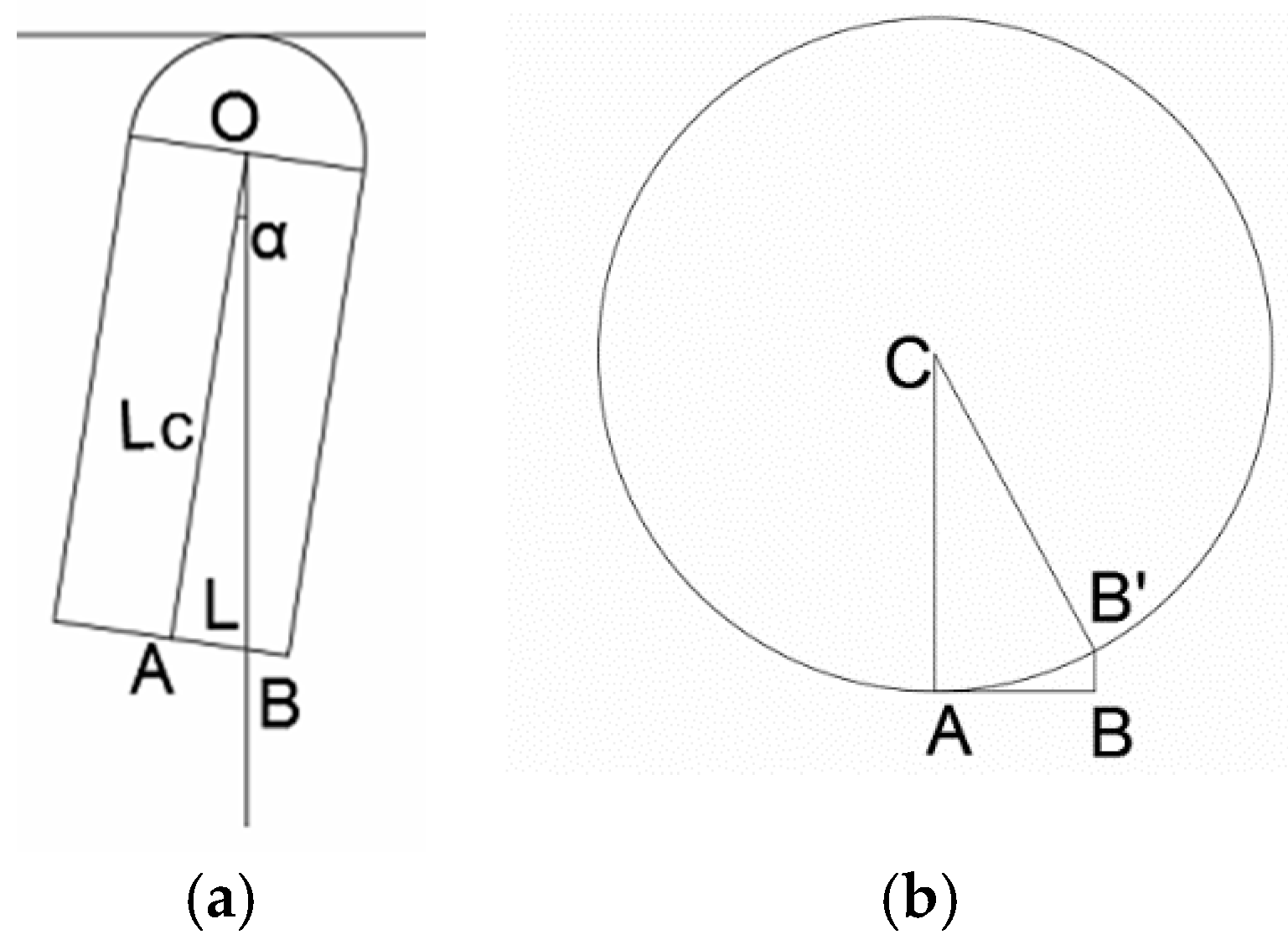
In order to identify different deflection angle during the experiment, a geometric relationship between the arc length of the rotor’s bottom edge (arc A B ^ in Figure 13b) and the deflection angle is established.
In Figure 13a, OA is the intersection line of the external interface of the rotor and the vertical plane. OB indicates the vertical direction and point B is the intersection point of the vertical line and the bottom surface of the rotor. B is the projection of point B on the bottom edge of the rotor along the direction of AC.
According to the geometric relationship there is:
| A B ^ | = | C B | s i n 1 ( | O A   s i n   α | | C B | )
In practical experiments, a serial of arc length A B ^ is previously drawn on the bottom edge of the rotor to identify different deflection angles. Therefore, we can compare the actual input electric currents and the expected value when the deflection angle changes from zero to ten degrees.
Since the maximum input electric current that the electromagnets can withstand for a long time is 3 A, the maximum deflection angle of the rotor is set as ten degrees.
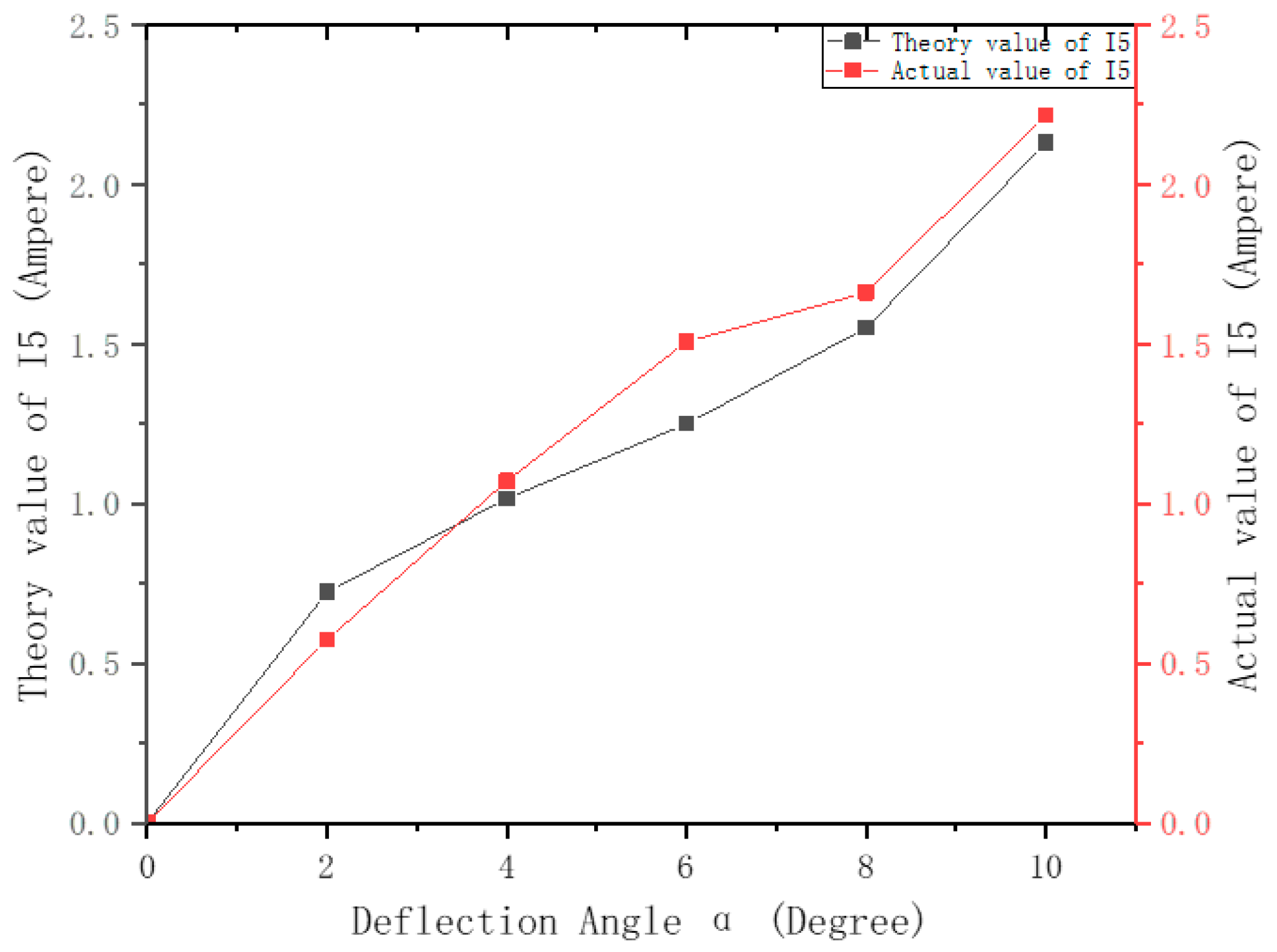
Figure 14 and Figure 15 shows the actual input electric currents and its expected value calculated from the model in Section 4. In order to solve the problem of multiple solutions, I 1 I 2 I 3 I 4 is set to a fixed value to achieve gravity compensation of the stator. The experimental results shown in Figure 13 and Figure 14 indicate that the model of deflection control of the rotor is correct and its average error is 11.72%. Thus, the accuracy of the deflection control model is verified.

6. Conclusions and Future Works

In this paper, an innovative laparoscopic robot system is proposed to solve the problem of instrumental interferences and visualization affection, whose position and orientation control can be achieved by magnetic fields. By mathematical modeling and force/torque analysis, the relationship between the input electric currents of the driving system (i.e., the stator) and the deflection angle of the laparoscopic robot (i.e., the rotor) is determined. In practical experiments, the position and orientation control of the rotor are achieved. By utilizing an external magnetic field, without utilizing a motor-based mechanism, the laparoscopic robot can be simpler in structure, smaller in size, and consume less energy, or there will be more room for other sensors.
In our future work, effort will be focused on two aspects: One is to optimize the present structure to increase the control range and the deflection angle of the rotor; the other lies in the fabrication of the power, wireless, IMU, and the camera unit inside the rotor. According to the feedback from the IMU unit, better accuracy of position and orientation control can be achieved.

Author Contributions

Data curation: K.L.; funding acquisition, H.W.; methodology: K.L. and D.X.; software: W.T.; supervision: H.W. and D.X.; writing—original draft: W.T.; writing—review and editing: W.T.

Funding

This research was funded by the National Natural Science Foundation of China grant number (No. 61673031) and (No. 61573038), and the APC was funded by the National Natural Science Foundation of China grant number (No. 61673031) and (No. 61573038).

Conflicts of Interest

The authors declare no conflict of interest.

References

  1. Díaz, C.E.; Fernández, R.; Armada, M.; Gutiérrez, F.d.J.G. State of the art in robots used in minimally invasive surgeries. Natural Orifice Transluminal Surgery (NOTES) as a particular case. Ind. Robot Int. J. Robot. Res. Appl. 2015, 42, 508–532. [Google Scholar] [CrossRef]
  2. Jung, Y.W.; Kim, S.W.; Kim, Y.T. Recent advances of robotic surgery and single port laparoscopy in gynecologic oncology. J. Gynecol. Oncol. 2009, 20, 137–144. [Google Scholar] [CrossRef] [PubMed] [Green Version]
  3. Díaz, C.E.; Fernández, R.; Armada, M.; García, F. A research review on clinical needs, technical requirements, and normativity in the design of surgical robots. Int. J. Med. Robot. Comput. Assist. Surg. 2017, 13. [Google Scholar] [CrossRef] [PubMed]
  4. Hu, T.; Allen, P.K.; Fowler, D.L. In-vivo pan/tilt endoscope with integrated light source. In Proceedings of the IEEE/RSJ International Conference on Intelligent Robots & Systems, San Diego, CA, USA, 29 October–2 November 2007; pp. 1284–1289. [Google Scholar]
  5. Hu, T.; Allen, P.K.; Hogle, N.J.; Fowler, D.L. Insertable surgical imaging device with pan, tilt, zoom, and lighting. In Proceedings of the IEEE International Conference on Robotics & Automation, Pasadena, CA, USA, 19–23 May 2008; pp. 2948–2953. [Google Scholar]
  6. Castro, C.A.; Alqassis, A.; Smith, S.; Ketterl, T.; Sun, Y.; Ross, S.; Rosemurgy, A.; Savage, P.P.; Gitlin, R.D. A wireless robot for networked laparoscopy. IEEE Trans. Biomed. Eng. 2013, 60, 930–936. [Google Scholar] [CrossRef] [PubMed]
  7. Platt, S.R.; Hawks, J.A.; Rentschler, M.E. Vision and task assistance using modular wireless in vivo surgical robots. IEEE Trans. Bio-Med. Eng. 2009, 56, 1700–1710. [Google Scholar] [CrossRef] [PubMed]
  8. Simi, M.; Silvestri, M.; Cavallotti, C.; Vatteroni, M.; Valdrastri, P.; Menciassi, A.; Dario, P. Magnetically activated stereoscopic vision system for laparoendoscopic single-site surgery. IEEE/ASME Trans. Mechatron. 2013, 18, 1140–1151. [Google Scholar] [CrossRef]
  9. Simi, M.; Sardi, G.; Valdastri, P.; Menciassi, A.; Dario, P. Magnetic Levitation camera robot for endoscopic surgery. In Proceedings of the IEEE International Conference on Robotics & Automation, Shanghai, China, 9–13 May 2011; pp. 5279–5284. [Google Scholar]
  10. Rossini, L.; Chetelat, O.; Onillon, E.; Perriard, Y. Force and torque analytical models of a reaction sphere actuator based on spherical harmonic rotation and decomposition. IEEE/ASME Trans. Mechatron. 2013, 18, 1006–1018. [Google Scholar] [CrossRef]
  11. Wang, W.; Wang, J.; Jewell, G.W.; Howe, D. Design and control of a novel spherical permanent magnet actuator with three degrees of freedom. IEEE/ASME Trans. Mechatron. 2003, 8, 457–468. [Google Scholar] [CrossRef]
  12. Kratochvil, B.E.; Kummer, M.P.; Abbott, J.J.; Kratochvil, B.E.; Borer, R.; Sengul, A.; Nelson, B.J. OctoMag: An electromagnetic system for 5-DOF wireless micromanipulation. IEEE Trans. Robot. 2010, 26, 1006–1017. [Google Scholar]
  13. Tracy, C.R.; Raman, J.D.; Cadeddu, J.A.; Rane, A. Laparoendoscopic single-site surgery in urology: where have we been and where are we heading? Nat. Rev. Urol. 2008, 5, 561. [Google Scholar] [CrossRef] [PubMed]
  14. Abbott, J.J.; Ergeneman, O.; Kummer, M.P.; Hirt, A.M.; Nelson, B.J. Modeling magnetic torque and force for controlled manipulation of soft-magnetic bodies. IEEE Trans. Robot. 2007, 23, 1247–1252. [Google Scholar] [CrossRef]
  15. Qualification Appraisal and Certification Committee of Civil Aviation Non-destructive Testing Staff. Magnetic Particle Test of Aircraft, 2nd ed.; China Civil Aviation Press: Beijing, China, 2009; ISBN 9787801108760. (In Chinese) [Google Scholar]
  16. Zhou, J.B.; Liu, B.Y.B. Magnetic Circuit and Magnetic Field, 1st ed.; Harbin Institute of Technology Press: Harbin, China, 1998; pp. 1–108. ISBN 7560312853. (In Chinese) [Google Scholar]
Figure 1. The prototype of laparoscopic robot system: (a) is the driving device (the stator) which is consist of five electromagnets, and (b) is the laparoscopic robot (the rotor).
Applsci 09 02070 g001
Figure 2. (a) shows the distribution of electromagnets in the stator and the IPMs in the rotor; (b) shows the working principle diagram of laparoscopic robot.
Applsci 09 02070 g002
Figure 3. (a) shows the connection between rotor and stator. (b) shows the structure and degrees of freedom (DOFs) of the rotor. In the conceptual design, the rotor consists of a head, a wireless unit, a power unit, an IMU, a control unit, and a camera. In this paper, only the head is fabricated. The coordinate described in (b) is fixed to the center of the hemispherical head of the robot. α indicates the deflection about the X or Y axis, while β indicates the rotation about the z axis.
Applsci 09 02070 g003
Figure 4. Cutaway view of the rotor.
Applsci 09 02070 g004
Figure 5. The relationship between maximum coil turns and the distance between the stator and the rotor (cutaway view).
Applsci 09 02070 g005
Figure 6. The relationship between the force of the vertical electromagnet to the rotor along z axis and the distance between them in different electric current densities.
Applsci 09 02070 g006
Figure 7. The comprehensive force of the stator to the rotor along z axis in different deflection angles.
Applsci 09 02070 g007
Figure 8. The physical structure of the experimental platform.
Applsci 09 02070 g008
Figure 9. The logical structure of the experimental platform.
Applsci 09 02070 g009
Figure 10. The translational and rotational motion of the rotor. (ac) exhibit the translational motion of the rotor in different position. (df) show the rotational motion of the rotor in different angle, where a black line on the rotor surface indicate the rotational motion of the rotor.
Applsci 09 02070 g010
Figure 11. The structure of the rotor used in experiment. (left) The cylindrical shell of the rotor. (middle) The hemispherical head of the rotor. (right) One of five permanent magnets installed on the hemispherical head.
Applsci 09 02070 g011
Figure 12. The deflection motion of the rotor. (a) shows the initial position of the rotor, and (b) exhibits the deflection motion of the rotor. In above figure, a rotary pair is utilized to equip the plumb and constrain the rotational motion of the rotor.
Applsci 09 02070 g012
Figure 13. The geometric relationship between arc A B ^ and the deflection angle α . (a) is the side view of Figure 12 and (b) is the top view of Figure 12. In practical experiments, the line OB is indicated by a tied hammer.
Applsci 09 02070 g013
Figure 14. The actual input electric current of I ( I 1 I 2 I 3 I 4 I 5 ) and its theoretical value in different deflection angles α ( I ) . I 1 is set as 2A, I 2 and I 3 is set as 1 A, I 4 is set as 0 A.
Applsci 09 02070 g014
Figure 15. The actual input electric current of I ( I 1 I 2 I 3 I 4 I 5 ) and its theoretical value in different deflection angles α ( I ) . I 1 is set as 2 A, I 2 and I 3 is set as 1.5 A, I 4 is set as 0 A.
Applsci 09 02070 g015
Table 1. Demagnetizing factor for soft magnetic materials with different length-diameter ratios.
NumberRatio of Length to DiameterMagnetic Susceptibility in the Long Axis
110.27
220.14
350.04
4100.0172
5200.00617
6500.00129
71000.00036