Abstract
Interest in the design of products that link performance and comfort is rapidly growing in the field of sport. To this end, the equipment industry is progressively shifting towards customization and it is focusing on man-machine interaction. The notion itself remains insufficiently studied by the scientific community. With regard to golf, several works conclude that vibrations that are perceived in the handle may be harmful and they have significant influence on comfort as well as performance. In that respect, the present paper investigates the effects of grip strength on three indicators of club dynamics: modal characteristics, overall vibratory levels, and vibration dose perceived by the club user, according to ISO 5349 standard. The study can be broken down into three steps. First, the experimental modal characteristics of a golf club are identified while using free-free, fixed-free, and grip-free (with three levels of grip strength) boundary conditions. Subsequently, a numerical model is developed and updated using experimental results. Finally, the root mean squared values and vibration dose transmitted to the hand-arm system after ball contact are extracted from the validated numerical model.
1. Introduction
Exposure of the human body to vibration is a well-established concern for industry. It is a source of discomfort, performance degradation, health, and safety risks [1,2]. In this matter, the measurement of vibration doses must follow the standard practice described in [3] and [4]. Besides, European Union (EU) directive EC/2002 [5] defines the prevention and risk thresholds. In the case of hand-arm system vibration, four types of injuries may be distinguished: vascular, neurological, carpal tunnel syndrome, and repetitive strain injury [6,7,8,9]. The literature also investigates the transmission of these vibrations, which is strongly correlated to body position, coupling forces [10,11], or handle size [12].
The works that are mentioned above are also relevant in the field of sport. In 2005, Issurin [13] carried out a thorough study on the possible beneficial applications of vibrations in sport, such as increasing flexibility, body strength, or oxygen consumption. In tennis, vibrations that are perceived by the athletes are considered to be a key parameter for comfort [14] as well as injury risk prevention [15,16]. In cycling, racers may undergo high levels of vibration doses [17], which are likely to cause the aneurysm of the ulnar artery [18] or paralysis of the ulnar nerve, mostly in amateur cyclists [19]. Vibrations that stem from the road profile are a determining factor in athlete’s comfort [20], and thus in performance [21]. Finally, in baseball, it has been demonstrated that the mechanical characteristics of the bat are directly related to the feeling of the player [22]. Furthermore, the literature suggests that the sound of impact in sports is linked to the feeling of the athletes. The sound is the image of the longer batted bat distance in baseball, [23], and the feeling is good for a loud sharp sound in golf [24]. In tennis, the sound allows for discriminating the string tension [25]. Thus, the engineering design takes account of the sound, [26].
Golf is also concerned by vibration exposure: being a sporting activity that is predominantly focused on dexterity, particular attention must be drawn to the design of the club for performance and comfort purposes. The related mechanical characteristics are widely studied in the literature, and the vibratory behavior of the club is unquestionably one of the most important. It turns out that club vibrations generated during the contact with the ball play a part in the feeling and performance of the participant. Osis and Stefanyshyn [27] showed that vibrations of the club shaft decrease the golfer’s accuracy, since they propagate up to body joints (wrist and elbow). In 2005, Roberts et al. [28] concluded that out of experience, golfers perceive a high dose of vibrations whenever swing is improperly executed: therefore, vibratory feedback is intimately related to performance. The influence of various mechanical parameters on the vibratory behavior was assessed in several studies, such as the effect of fixed boundary conditions, the choice of material [29], or the development of numerical models that are updated using modal analysis [30,31]. However, to the authors’ knowledge, the literature does not investigate the effect of grip strength on the vibratory behavior of a golf club, despite evidence of its ability to significantly remove the structural response in other activities [32]. Another in situ observation is that amateur players tend to apply a greater grip force on the club shaft than professional players, which could play a major role in the development of specific diseases, such as tendinitis among amateur players [33].
The aim of this paper is to complement these research studies by focusing on the grip strength and its effect on hand-arm vibration during ball contact. Section 2 of the present paper describes the standard governing the calculation of vibration doses on the human body. Section 3 presents the experimental modal analysis of a golf club while using three types of boundary conditions (free-free, fixed-free, and grip-free with three levels of grip force). This analysis will make it possible to identify the dynamic behavior of the club. Next, Section 4 is dedicated to the formulation of a numerical, finite element (FE)-based model of the golf club, which is updated using test campaigns that are described in Section 2. Subsequently, Section 5 assesses the global vibration levels of the club, and then the vibration doses are perceived depending on the grip strength. Finally, the results are discussed and lead to conclusions and prospects in the matter.
2. ISO 5349 Standard
The ISO 5349 standard describes the methodology to be used in the measurement and a calculation of vibration doses undergone by the human body and transmitted through the hand [3]. Measurement will be preferentially carried out along all three axes and at the hand-tool interface. Vibratory dose () is deducted from the weighted accelerations along the three axes, , , , Equation (1).
Weighting stands for the risk probability related to each frequency, and it consists in the product of a band-limiting filter and a weighting filter , Equation (2). The values refer to resonance frequencies (), while refer to the selectivities of these poles (). Finally, stands for the gain ().
3. Experimental Model
The studied shaft, as presented in Figure 1, is a Hybrid 500 MEN’S RH that is made by INESIS (Decathlon, Lille, France), displaying a loft. The structure is divided in three parts, each made of a different material: an aluminium head, a carbon-epoxy composite shaft, and an ethylene propylene diene monomer (EPDM) rubber grip. The corresponding mechanical parameters are extracted from the literature [34] and are presented in Table 1.
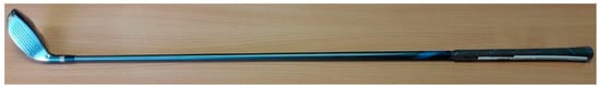
Figure 1.
Studied club (length 101.6 cm).

Table 1.
Mechanical characteristics of the golf shaft before updating, [34]. The parameters are as follows: for Young’s modulus, for Poisson’s ratio, and for shear modulus.
A discretized model is designed using OROS Modal software (OROS, Grenoble, France) in order to rebuild the modal shapes, and it comprises four segments three connected by five nodes. One node represents the three-axis observabilities recorded by a piezoelectric accelerometer (B&K4525, Bruel and Kjaer, Duluth, USA). The other four nodes stand for the three-axis controllabilities, i.e., twelve controllabilities. Excitation is performed using a shock hammer equipped with a force sensor (208C02, PCB Piezotronics, Buffalo, USA), as seen in Figure 2. Synchronous data collection is supplied by an OROS acquisition system (OR36, OROS, France).
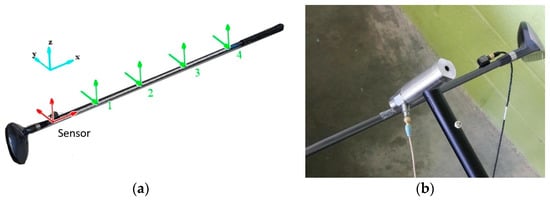
Figure 2.
(a) Discretized model in OROS Modal. The sensor is a piezoelectric accelerometer, while 1, 2, 3, 4 are the impact locations spaced 12.5 cm apart. (b) Example of experimental modal analysis.
Five different sets of boundary conditions are tested. The first two are classical free-free and fixed-free boundary conditions. In the free-free case, the shaft is hung while using elastic cords in order to isolate it from external perturbations. In the fixed-free case, the grip of the shaft measuring 21.5 cm is clamped in a bench vice that is mounted on a slotted plate. With regard to the last three boundary conditions, called “grip-free”, a male participant (37 years old, 173 cm tall, 70 kg) was involved in the study. The local ethic committee approved the experiment and the participant signed a consent form. Modal analyses are performed while having the participant exert hand pressure on the grip, at three different levels. The contact pressure is recorded and visualized in real time using two pre-calibrated pressure mats (Grip System, Tekscan, Boston, MA, USA) (see Figure 3). The participant is able to achieve near constant pressure intensity by visualizing the value of mean pressure on both hands, as is depicted in Table 2.
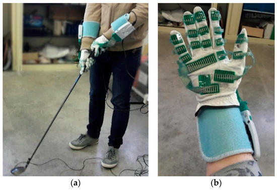
Figure 3.
(a) Experimental modal analysis in grip-free boundary conditions. (b) Glove equipped with pressure sensors.
Table 2.
Measurements of contact pressure and surfaces in various grip strength conditions.
Modal characteristics, frequencies, and damping are extracted using OROS Modal software (OROS, France) and Table 3 summarizes them. The Broband algorithm is used for identification in the 0–500 Hz range, which is characterized by a vibratory risk probability between 0.025 and 1, according to ISO 5349 standard, Equation (2). This algorithm implements the LSCF (Least Squares Complex Frequency) identification method, which offers higher accuracy when compared to SIMO (Single Input Multiple Outputs) methods on coupled modes, thus leading to improved modal estimations [35].
Table 3.
Identification of modal data. The deformed shapes correspond to bending. The results are expressed in Frequency-Hz (Damping-%). (-) corresponds to an undefined value.
The modal density over the studied frequency range is low, as only eight modes are identified. Four modes are located in the x-y plane and four others in the x-z plane. It is worth mentioning that the identified modal frequencies are consistent with the works by Braunwart [29]. These modes are the first four bending modes in the x-y and x-z planes. No torsion mode is highlighted, with the sensor and impact locations being aligned on the longitudinal axis of the golf club. Section 5 discusses the effect of gripping on the modes.
4. Finite Element Numerical Model
4.1. Shaft Modeling
The first step in the development of the numerical model consisted in the scan of the head, while using the DAVID 3D Scanner 4 system (HP, Palo Alto, CA, USA) comprised of a projector, a camera, and a rotating plate. The resulting geometry, as depicted in Figure 4a, was then imported in general purpose CAD software SolidWorks (Dassault Systems, Paris, France). The dimensions of the shaft and grip were too large to allow for scanning, so the decision was made to directly model them using the CAD software, with geometry measurements being carried out using a measuring tape and a sliding caliper. The whole shaft model, as presented in Figure 4b, was then imported in FEA software Abaqus 6.14 (Simulia, Paris, France). For computational cost purposes, the shell elements were selected due to the low thickness of all three components in the assembly: the carbon-epoxy composite shaft is 1.5 mm thick, while the aluminium head and rubber grip are both 3 mm thick. Ultimately, the overall mesh contains 27061 four-node shell elements with reduced integration (S4R elements). Based on the works by [36,37], the shaft material is assumed to be an orthotropic, carbon-epoxy composite, while the grip and head can reasonably be considered isotropic. Table 1 summarizes all of the required mechanical properties.
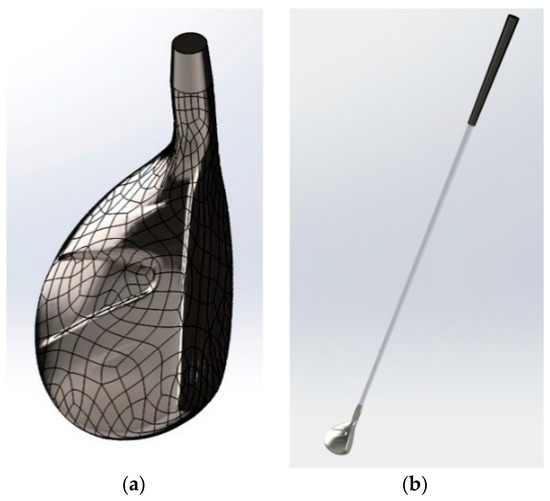
Figure 4.
(a) Three-dimensional (3D) scan of the head, imported in SolidWorks. (b) Whole numerical model of the golf shaft.
A three-step model updating was performed. First, two three-point bending tests, one numerical and the other experimental, were compared, so as to update the Young’s modulus of the shaft. The updated value is 92,550 MPa. After updating and considering the fixed-free boundary conditions, the MAC (Modal Assurance Criterion) matrices were used to determine the similarity of the identified and numerical eigenmodes (Figure 5). The coefficients are bounded between 0 and 1, with 1 indicating fully consistent eigenmodes. A value near 0 indicates that the modes are not consistent [38]. Prior to updating, the discrepancies between model and experiment ranged from 4.82 to 36.93% but decreased to a 2.04–4.21% interval afterwards, Table 4. Only the first two modes retain significant post-updating differences, 18.24 and 33.00%, respectively. The Modal Assurance Criterion (MAC) matrices highlight good identification of modal shapes, with diagonal values above 0.80, except for mode 2 (0.56). However, it should be noted that modes 4 and 2 are only slightly decoupled, which may be attributable to a lack of observability during experimental modal analysis.
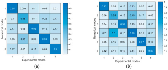
Figure 5.
MAC (Modal Assurance Criterion) matrices computed for identified and numerical eigenmodes after updating in (a) free-free and (b) fixed-free boundary conditions.
Table 4.
Experimental and numerical modal frequencies (Hz) before and after updating.
4.2. Modeling of Contact between the Ball and Club Head
The effect of grip strength on the perceived vibratory dose was investigated by modeling the contact of a golf ball on the club head, while the grip is being maintained. As a preliminary approach, a pressure of 19 MPa was applied on a circle of 24 mm diameter that was located at the center of the head, for a duration of 0.5 ms (see Figure 6a) [39]. Given the small size of some finite elements in the mesh, using a dynamic explicit procedure to simulate contact between the ball and club head would have resulted in very long computations. The reason being that the stable time increment, as computed by the code, is proportional to the size of the smallest finite element in the whole mesh. Implicit dynamic procedures are a trustworthy alternative whenever the strains as well as inertial effects remain limited, which is verified in the present case. However, in this frame, the algorithm for convergence acceleration purposes automatically sets numerical damping, and it affects any material damping previously defined. The parameter cannot be accessed either, which is unfortunate, as it could have provided a starting point for any further improvement in the dynamic behavior of the club. No specific material damping was thus defined in the model, and accuracy could certainly be further improved by refining these parameters. The grip strength that is applied by the golfer is modeled through the definition of eight surfaces on the grip: one for each finger, one for the upper part of the palm, and two for its lower part. To this end, three different numerical models are implemented, with each displaying its own hand-grip interfaces since the contact zones evolve along with grip strength. Figure 6b depicts all models.
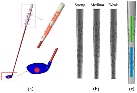
Figure 6.
(a) Modeling of ball contact and grip zones; (b) Representation of grip zones on the numerical model by grip strength; and, (c) Reference points used to calculate vibratory doses.
5. Influence of Grip Strength
5.1. On the Modal Characteristics
Based on the results of experimental modal analysis that is detailed in Section 3, grip strength affects the identified modal frequencies. It can be clearly observed from Table 3 that eigenfrequencies decrease as grip strength increases and converge towards the values that were calculated in fixed-free boundary conditions, except for mode 8. Below 100 Hz, the frequencies only vary by a few hertz as the grip force increases: therefore, it can be assumed to have negligible influence in this range. Beyond 200 Hz, relative variations between weak and strong grip pressure range from 0.75 to 8.00%, i.e., frequency variations of 31 Hz for mode 8. As a conclusion, the influence of grip strength on eigenfrequencies remains limited.
5.2. On the Values of Total Accelerations
Root mean square of the accelerations (RMS values) are estimated for three timeframes after applying grip pressure, as seen in Table 5. The time frames are noted for ranges [ respectively. The smallest RMS value, being averaged over these time frames, is observed in the case of medium grip force with a gain of at time frame , which represents of the RMS value. At time frame , the RMS values for all three levels of grip force only differ by 4 . Finally, at time frame , the strong and medium grips are similar; however, the RMS value for weak grip is 20–23 higher.
Table 5.
Evolution of root mean square (RMS) value () after contact.
It is also observed that vibrations are lower when the participant holds the shaft with medium grip force, and that a longer period of time is required to completely dampen shock in the case of weak grip.
5.3. On the Vibratory Doses
The accelerations are measured at the center of the palm of each hand in accordance with ISO 5349 standard, as seen in Figure 3. Based on these signals, the values of vibratory doses and are calculated for both left and right hand-arm systems and are summarized in Table 6. A mean difference of 13.6% is observed between the two systems, and the right one appears to be more influenced, with a mean value of 3.05 . By referring to the thresholds of prevention (2.5) and risk (5 ) that were laid down in the corresponding European directive [5], and assuming eight hours of daily exposure, the participant should take preventive measures after 5h22, which is broadly acceptable in terms of health safety. The influence of grip strength is moderate for both hand-arm systems, with the highest variation observed being 0.08 , i.e., a relative difference of 1.3%. In the end, grip force does not seem to be a key parameter in the decrease of vibratory doses.
Table 6.
Weighted effective values of acceleration [3].
6. Discussion
The works presented herein rely on experimental modal analyses, with the purpose of readjusting the numerical model and assessing the influence of grip force on the modal behavior of the shaft. The values of eigenfrequencies that were identified in standard boundary conditions (i.e., free and fixed) compare quite well to those found in the literature, even if the clubs are different [29,30,40]. Goff [41] reports that skin is sensitive to vibrations up to 500 Hz, with enhanced sensitivity in the range 100–320 Hz. Subsequently, the participant may be sensitive to the first three modes in each plane. Modal analysis in the case of grip-free BCs highlights the limited influence of the grip force on the modal frequencies of the shaft, but a much greater one on damping. A mean difference of 1.02% is observed in frequencies, with a range of 0.00 to 4.22%. Regarding damping, the mean difference is 26.51% and it lies within the range −7.98–82.14%. The seventh mode is the most affected by the level of grip force, which corroborates the conclusions that are drawn in the scientific literature. The effect on modal damping is confirmed in the works by Chadefaux et al. [32] on tennis rackets and those by Russell [42] on baseball bats and hockey sticks. These studies show that the damping values increase with the level of grip strength. However, broader variations are stated regarding eigenfrequencies: for instance, Chadefaux et al. [32] highlight a decrease of 15% (±5%) between the low and high levels of grip.
The present paper concludes that the RMS value is minimal for a moderate grip force, which appears to be optimal in terms of performance and comfort, although not all users adhere to it. Farber et al. [33] report that amateurs tend to exert a higher grip force on the shaft than professionals, particularly in the ascending phase of the shaft. Besides, the development of medial epicondylitis, which is favored by vibrations, turns out to be more frequent in amateur golfers (24%) than in professional or high-level amateur players (4%) [43,44]. Hence, a correlation between the amateur population and vibratory dose may partly account for medial epicondylitis.
Based on the standards governing the calculation of vibratory doses, the present study shows that the right hand-arm system (for a right-handed player) is more exposed than the left system. A discrepancy below 1.3% exists between the vibratory doses for all three levels of grip strength, which enables us to conclude that it is not a determining factor in their decrease. However, the RMS value of acceleration varies by 23 m/s2, depending on the grip force: in this regard, spectral content is key. For the three different intensities of grip strength, spectral analysis actually shows that 86% of the spectral content lies in the 95–110 Hz range, with the interval of interest being 0–400 Hz. Relying on the frequency weighting curve from standard ISO 5349-2, the 95–110 Hz range shall be given a 0.1 weighting factor, with this factor decreasing beyond 100 Hz. This calculation method justifies the small gap between the values of in Table 5: the frequency weighting diminishes the amplitude of discrepancies. The results show that the limit duration is 5h22; however, a golfer is not submitted to continuous vibration during this duration per day. Thus, the ISO5349 seems to be inadequate to give a recommendation for the golf activity.
The dynamic behavior of the golf shaft is also found to be altered by the intensity of grip force as well as boundary conditions. Besides, the related literature mentions that the participant adjusts the grip force during the swing [45] and as a function of exhaustion [46]. Therefore, our analysis should be extended to actual motor conditions by implementing Operational Modal Analysis (OMA). Operational Modal Analysis or output-only modal analysis [47] provides information regarding the modal parameters by replacing the deterministic knowledge of the input signal with the assumption that the input is a realization of a stochastic process, i.e., white noise. In our case, the ball would be used as the exciter instead of a shock hammer, which allows for us to conclude whether impact triggers the same eigenfrequencies as those identified during EMA. For instance, this technique is used in the works of Mucchi [48] as a means of characterizing the so-called “sweet spot” in beach tennis rackets. Despite low values of MACs (0.53 et 0.48), the eigenmodes that are identified by EMA and OMA have similar shapes.
The present work also provides a numerical model updated on experimental tests, which is able to simulate contact between the ball and the club head and compute the vibratory doses perceived by the participant. It can be used to initiate further simulations on different materials, geometries, or hand placements [49]. Cheong et al. [36] conclude that the mechanical performance of the shaft is greatly influenced by the fiber orientation; Petersen and McPhee [50] optimize the club head and increase the speed at impact by 4.8 m/s, resulting in a 20 m longer shot distance. The contact is simulated at the center of the head without taking the modal shape of the shaft into account. Yet, studies show how important these shapes are in the identification of the sweet spot, which corresponds to a vibration node [30]. To this end, performing a modal analysis on the putter would allow for refining the model and assessing the effects of a misplaced hit. Finally, it has also been demonstrated that vibration feedback is associated to an incorrect hit [28]. A ball might be simulated and studied in order to compute its kinetic energy after being hit, similarly to the finite element simulations that were conducted by Petersen and McPhee [50] on the collision of the ball and club head.
Finally, the results are obtained with a right-handed participant and a club. A large panel of participants must be investigated, involving left and right-handed, male and female golfers, to analyze the influence of parameters, such as the modulation of surface grip or the position of the upper limbs. The same goes for different types of clubs: The geometry and material of the club play an important role on dynamic characteristics and quantifying their influence on vibratory indicators is relevant.
7. Conclusions/Prospects
The work that is presented in this study focuses on the numerical simulation of the contact of a golf ball on a club head, in an attempt to assess the dynamic characteristics of the club: modal parameters (eigenfrequencies and eigenmodes), the root mean square of the accelerations (RMS values), and vibratory doses expressed in terms of standard IS0 5349-2. The model is based on an updated golf club model and the analysis of three levels of grip strength.
Three major results are highlighted. (i) Simulation makes it possible to integrate the grip pressure map experimentally obtained and calculate the vibratory doses and RMS values. (ii) The results show that grip strength affects the modal parameters of the club. Eigenfrequencies decrease with grip pressure, while the damping values decrease. (iii) The right hand-arm system (for a right-handed player) undergoes a dose of 2.32 , i.e., a 13.6 increase as compared to the left one. Grip strength is not a significant parameter in vibratory doses (mean 1.3% variation), although a trend seems to show that moderate pressure (0.044 MPa for the participant in this study) is optimal.
Two further applications of this research work are possible. First, experiments must be carried out with the aim of validating the vibratory doses, as well as determining the modal characteristics using operational modal analysis: in such a way, we may improve knowledge regarding the dynamic behavior of the club in actual motor conditions. The second application is about simulation, and it should mainly be aimed at developing a numerical model that is able to implement new materials or grip strategies.
Author Contributions
X.C. planned, performed the experiments and supervised the research work, S.M. designed the numerical model and updated it. G.K. and R.S. provided suggestions on the results and revised the entire manuscript.
Funding
This research received no external funding.
Conflicts of Interest
The authors declare no conflict of interest.
References
- Taiar, R.; Machado, C.B.; Chiementin, X.; Bernardo-Filho, M. Whole Body Vibrations: Physical and Biological Effects on the Human Body, 1st ed.; CRC Press: Boca Raton, FL, USA, 2018. [Google Scholar]
- Griffin, M.J. Handbook of Human Vibration; Academic Press: Cambridge, MA, USA, 1990. [Google Scholar]
- International Organization for Standardization. ISO5349-1, “Mechanical Vibration—Measurement and Evaluation of Human Exposure to Hand-Transmitted Vibration—Part 1: General Requirements”; International Organization for Standardization: Geneva, Switzerland, 2001. [Google Scholar]
- International Organization for Standardization. ISO 2631-1, ISO 2631-1:1997—Mechanical Vibration and Shock—Evaluation of Human Exposure to Whole-Body Vibration—Part 1: General Requirements; International Organization for Standardization: Geneva, Switzerland, 1997. [Google Scholar]
- Council of the European Union; European Parliament. Directive 2002/44/EC, “Directive 2002/44/EC of the European Parliament on the Minimum Health and Safety Requirements Regarding the Exposure of Workers to the Risks Arising from Physical Agents (Vibration)”; Council of the European Union, European Parliament: Luxembourg, 2002. [Google Scholar]
- Friden, J. Vibration damage to the hand: Clinical presentation, prognosis and length and severity of vibration required. J. Hand Surg. J. Br. Soc. Surg. Hand 2001, 26, 471–474. [Google Scholar] [CrossRef]
- Pyykkö, I.; Färkkilä, M.; Toivanen, J.; Korhonen, O.; Hyvärinen, J. Transmission of vibration in the hand-arm system with special reference to changes in compression force and acceleration. Scand. J. Work Environ. Health 1976, 2, 87–95. [Google Scholar] [CrossRef]
- Bovenzi, M.; Petronio, L.; DiMarino, F. Epidemiological survey of shipyard workers exposed to hand-arm vibration. Int. Arch. Occup. Environ. Health 1980, 46, 251–266. [Google Scholar] [CrossRef]
- Taylor, W. Biological effects of the hand-arm vibration syndrome: Historical perspective and current research. J. Acoust. Soc. Am. 1988, 83, 415–422. [Google Scholar] [CrossRef]
- Pekkarinen, J.; Starck, J.; Pyyko, I. High-speed digital method to measure impulsive hand–arm vibration. In Proceedings of the 3rd International Symposium of the ISSA, Vienna, Austria, 19–21 April 1989. [Google Scholar]
- Starck, J.; Pekkarinen, J.; Chun, L.C. Transmission of vibration from tool handle to wrist and to head. Kurume Med. J. 1990, 37, S1–S11. [Google Scholar] [CrossRef]
- Aldien, Y.; Marcotte, P.; Rakheja, S.; Boileau, P.-É. Influence of hand forces and handle size on power absorption of the human hand–arm exposed to zh-axis vibration. J. Sound Vib. 2006, 290, 1015–1039. [Google Scholar] [CrossRef]
- Issurin, V.B. Vibrations and their applications in sport. A review. J. Sports Med. Phys. Fit. 2005, 45, 324–336. [Google Scholar]
- Stroede, C.L.; Noble, L.; Walker, H.S. The effect of tennis racket string vibration dampers on racket handle vibrations and discomfort following impacts. J. Sports Sci. 1999, 17, 379–385. [Google Scholar] [CrossRef]
- Brody, B.; Létourneau, Y.; Poirier, A. Le coût des accidents du travail: État des connaissances. Relat. Ind. 1990, 45, 94–117. [Google Scholar] [CrossRef]
- Allen, T.; Dixon, S.; Dunn, M.; Knudson, D. Tennis Equipment and Technique Interactions on Risk of Overuse Injuries. In Tennis Medicine; Springer International Publishing: Cham, Switzerland, 2018; pp. 61–79. [Google Scholar]
- Chiementin, X.; Rigaut, M.; Crequy, S.; Bolaers, F.; Bertucci, W. Hand–arm vibration in cycling. J. Vib. Control 2013, 19, 2551–2560. [Google Scholar] [CrossRef]
- Rtaimate, M.; Farez, E.; Lariviere, J.; Limousin, M.; Laffargue, P. Aneurysm of the ulnar artery in a mountain biker, a case report and review of the literature. Chirurgie de la Main 2002, 21, 362–365. [Google Scholar] [CrossRef]
- Haloua, J.P.; Collin, J.P.; Coudeyre, L. Paralysis of the ulnar nerve in cyclists. Ann. Chir. Main 1987, 6, 282–287. [Google Scholar] [CrossRef]
- Parkin, J.; Sainte Cluque, E.; Parkin, J.; Sainte Cluque, E. The impact of vibration on comfort and bodily stress while cycling. In Proceedings of the UTSG 46th Annual Conference, Newcastle University, Newcastle, UK, 6–8 January 2014. [Google Scholar]
- Ayachi, F.S.; Dorey, J.; Guastavino, C. Identifying factors of bicycle comfort: An online survey with enthusiast cyclists. Appl. Ergon. 2015, 46, 124–136. [Google Scholar] [CrossRef]
- Noble, L.; Walker, H. Baseball Bat Inertial and Vibrational Characteristics and Discomfort Following Ball–Bat Impacts. J. Appl. Biomech. 1994, 10, 132–144. [Google Scholar] [CrossRef]
- Tabuchi, N. Effect of rubber-ball baseball playing experience on the batted ball sound evaluation. Proc. Symp. Sport. Hum. Dyn. 2015, 28, 1–6. [Google Scholar]
- Roberts, J.R.; Jones, R.; Mansfield, N.J.; Rothberg, S.J. Evaluation of impact sound on the ‘feel’ of a golf shot. J. Sound Vib. 2005, 287, 651–666. [Google Scholar] [CrossRef][Green Version]
- Bower, R.; Cross, R. Player sensitivity to changes in string tension in a tennis racket. J. Sci. Med. Sport 2003, 6, 120–131. [Google Scholar] [CrossRef]
- Steele, C.; Jones, R.; Leaney, P. Improved tennis ball design: Incorporating mechanical and psychological influences. J. Eng. Des. 2008, 19, 269–284. [Google Scholar] [CrossRef]
- Osis, S.T.; Stefanyshyn, D.J. Vibration at the wrist and elbow joints during the golf swing reveals shaft-specific swing kinematics. Procedia Eng. 2010, 2, 2637–2642. [Google Scholar] [CrossRef][Green Version]
- Roberts, J.R.; Jones, R.; Mansfield, N.J.; Rothberg, S.J. Evaluation of vibrotactile sensations in the ‘feel’ of a golf shot. J. Sound Vib. 2005, 285, 303–319. [Google Scholar] [CrossRef]
- Braunwart, P.R. Experimental and Analytical Examination of Golf Club Dynamics. Ph.D. Thesis, Virginia Tech, Blacksburg, Virginia, March 1999. [Google Scholar]
- Friswell, M.I.; Mottershead, J.E.; Smart, M.G. Dynamic models of golf clubs. Sport. Eng. 1998, 1, 41–50. [Google Scholar] [CrossRef]
- Sandhu, S.; Millard, M.; Mcphee, J.; Brekke, D. 3D Dynamic Modelling and Simulation of a Golf Drive. Procedia Eng. 2010, 2, 3243–3248. [Google Scholar] [CrossRef]
- Chadefaux, D.; Rao, G.; Le Carrou, J.-L.; Berton, E.; Vigouroux, L. The effects of player grip on the dynamic behaviour of a tennis racket. J. Sports Sci. 2017, 35, 1155–1164. [Google Scholar] [CrossRef]
- Farber, A.J.; Smith, J.S.; Kvitne, R.S.; Mohr, K.J.; Shin, S.S. Electromyographic Analysis of Forearm Muscles in Professional and Amateur Golfers. Am. J. Sports Med. 2009, 37, 396–401. [Google Scholar] [CrossRef]
- Carma. Glossaire des Matériaux Composites—Actualisation; Région Provence - Alpes Côte d’Azur, CARMA: Washington, DC, USA, 2006. [Google Scholar]
- Guillaume, P.; Van der Auweraer, H.; Vanlanduit, S.; Peeters, B. A poly-reference implementation of the least-squares complex frequency-domain estimator. In Proceedings of the IMAC, Kissimmee, FL, USA, 3–6 February 2003; Volume 21. [Google Scholar]
- Cheong, S.K.; Kang, K.W.; Jeong, S.K. Evaluation of the mechanical performance of golf shafts. Eng. Fail. Anal. 2006, 13, 464–473. [Google Scholar] [CrossRef]
- Tanaka, K.; Sekizawa, K. Construction of a Finite Element Model of Golf Clubs and Influence of Shaft Stiffness on Its Dynamic Behavior. Proceedings 2018, 2, 247. [Google Scholar] [CrossRef]
- Allemang, R. The modal assurance criterion—Twenty years of use and abuse. Sound Vib. 2003, 37, 14–23. [Google Scholar]
- Arakawa, K.; Mada, T.; Komatsu, H.; Shimizu, T.; Satou, M.; Takehara, K.; Etoh, G. Dynamic Deformation Behavior of a Golf Ball during Normal Impact. Exp. Mech. 2009, 49, 471–477. [Google Scholar] [CrossRef]
- Thomas, G.; Deiters, T.; Best, C. Simulating golf club performance using modal analysis. In Proceedings of the 13th International Modal Analysis Conference, Nashville, TN, USA, 13–16 February 1995. [Google Scholar]
- Goff, G.D. Differential discrimination of frequency of cutaneous mechanical vibration. J. Exp. Psychol. 1967, 74 Pt 1, 294–299. [Google Scholar] [CrossRef]
- Russell, D.A. Flexural vibration and the perception of sting in hand-held sports implements. In Proceedings of the 41st International Congress and Exposition on Noise Control Engineering, New York, NY, USA, 19–22 August 2012; Volume 2012, pp. 10111–10119. [Google Scholar]
- McCarroll, J.R.; Rettig, A.C.; Shelbourne, K.D. Injuries in the Amateur Golfer. Phys. Sportsmed. 1990, 18, 122–126. [Google Scholar] [CrossRef]
- Kohn, H.S. Prevention and treatment of elbow injuries in golf. Clin. Sports Med. 1996, 15, 65–83. [Google Scholar]
- Knudson, D.V. Forces on the Hand in the Tennis One-Handed Backhand. Int. J. Sport Biomech. 1991, 7, 282–292. [Google Scholar] [CrossRef]
- Rossi, J.; Berton, E.; Grélot, L.; Barla, C.; Vigouroux, L. Characterisation of forces exerted by the entire hand during the power grip: Effect of the handle diameter. Ergonomics 2012, 55, 682–692. [Google Scholar] [CrossRef]
- Peeters, B.; Van Der Auweraer, H. Polymax: A revolution in operational modal analysis. In Proceedings of the 1st International Operational Modal Analysis Conference, Copenhagen, Denmark, 26–27 April 2005. [Google Scholar]
- Mucchi, E. On the sweet spot estimation in beach tennis rackets. Measurement 2013, 46, 1399–1410. [Google Scholar] [CrossRef]
- Hung, G.K. Effect of Putting Grip on Eye and Head Movements During the Golf Putting Stroke. Sci. World J. 2003, 3, 122–137. [Google Scholar] [CrossRef]
- Petersen, W.; McPhee, J. Shape optimization of golf clubface using finite element impact models. Sport. Eng. 2009, 12, 77–85. [Google Scholar] [CrossRef]
© 2019 by the authors. Licensee MDPI, Basel, Switzerland. This article is an open access article distributed under the terms and conditions of the Creative Commons Attribution (CC BY) license (http://creativecommons.org/licenses/by/4.0/).