Abstract
The conventional resonance conditions are derived based on the conventionally designed impellers without splitter blades. This paper proposes the resonance conditions for impellers under the excitation from the impeller–diffuser interaction with attention paid on the influence of splitter blades. A lumped parameter model is established and the modal analysis is carried out. The blade-based representative modal vector (RMV) is defined. The influence of splitter blades on the impeller’s traits of modes is investigated by analyzing the spatial harmonic contents of the RMV. Then, given the specific form of the diffuser-induced engine order excitation acting on the main and splitter blades, the resonance conditions are derived. Tuned and mistuned cases are provided for a practical impeller. The resonance conditions are verified by harmonic response calculations. The applications of the proposed resonance conditions in resonance identification and hazard evaluation of different excitations are given. The differences between the proposed resonance conditions and the conventional ones are discussed. The research indicates that even the RMV of the tuned impeller contains two harmonic components due to the existence of splitter blades. When the excitation frequency equals the natural frequency of the impeller and the excitation order matches with either harmonic index of the two harmonics, the resonance occurs. The results of case studies show that the harmfulness of various engine orders of excitation can be exactly evaluated by the joint use of the spatial harmonic contents analysis result and the proposed resonance conditions; however, analyzing based on the conventional resonance conditions may lead to the misjudgment of the harmfulness of the excitations.
1. Introduction
Centrifugal compressors are widely used in gas turbine engines, turbochargers, and oil and gas industries [1,2,3]. The impeller is the vital component of the compressor. It can be classified as two types according to whether it has splitter blades: the conventionally designed impeller and the impeller with splitter blades. Research shows that adding splitter blades not only helps reduce blade loadings but also can improve the compressor performance [4,5,6]. Thus, the impellers with splitter blades are more and more used in engineering [7,8,9].
For both conventionally designed impellers and impellers with splitter blades, high cycle fatigue (HCF) failure due to the forced vibration under the aerodynamic excitation is the main failure form [10,11,12]. The excitation from the impeller–diffuser interaction is the main excitation acting on the impeller. Because the impeller–diffuser radial gap is becoming smaller by design [13,14], the interaction is getting more intense and the resulting unsteady aerodynamic loads are bigger. Moreover, the five-axis machine is now a common tool for impeller machining and the impeller is machined as one piece with very low structural damping [15,16]. As a result, these make the forced vibration of the impeller more prominent [17,18]. Especially when resonance occurs, the resulting excessive vibration stress contributes more to the HCF of the impeller, which threatens the engine’s reliability and integrity [19,20]. Therefore, it is essential to investigate the resonance conditions of the impeller for identifying the potential resonances within the frequency range of interest. Besides, during the design phase of the compressor, the resonance conditions can also be utilized for choosing the appropriate number of diffuser vanes to avoid the resonances [21].
The two types of impellers both belong to cyclic symmetric structures. Previous research has studied the resonance conditions of this kind of cyclic symmetric structure under traveling wave excitation, but only the conventionally designed impellers have been studied [22,23,24]. The research indicates that only when both the following conditions are simultaneously satisfied, can the resonance occur: (1) the frequency matching condition: the excitation frequency equals the natural frequency of the impeller ; (2) the shape matching condition: the harmonic excitation periodic shape matches the natural mode shape. From that, it can be seen that the resonance conditions of impellers are closely associated with two aspects of both the structural natural characteristics and excitation characteristics. However, due to the existence of the splitter blades, there are differences between these two types of impellers in the above two aspects. For instance, in most designs of impellers with splitter blades, splitter blades have the same blade profiles as the main blades but with shorter chord length. They are usually placed at the midpitch of the two main blades. In terms of aerodynmic forcing, the spatial harmonic contents of the unsteady pressure distribution at the impeller exit for impellers with splitter blades are different from those for conventionally desinged ones [25]. Besides, the load amplitudes of the main and the splitter blades are usually different too [25,26,27].
Despite the above differences, very little attention has been paid to the influence of splitter blades on the resonance conditions of impellers. In most research, the vibration characteristics of the impellers are only analyzed based on the duplicated sector by utilizing the structural cyclic symmetry, and the influence of splitter blades is ignored. For example, Wu et al. [28] proposed a cyclic symmetry method for analyzing the impeller’s dynamic characteristics, but the cyclosymmetry of which was demonstrated only from the perspective of the main blade mode shapes. Zhang et al. [29] conducted vibration analysis based on the duplicated sector of the impeller during multidisciplinary design optimization for a centrifugal compressor, but only the modal frequency was investigated. Weber et al. [30] also performed modal analysis based on the duplicated sector with focus on mistuning identification for the high-speed centrifugal impeller. Wang et at. [31] investigated the effects of cracks on the resonance characteristics. As a continuation of Wang et al.’s research, Chen et al. [32] proposed the quantitative identification method for blade crack faults in the centrifugal impeller based on the historical sensor-dependent vibration data. When calculating the forced response in the numerical simulation parts of their research, the engine order excitation was only applied on the main blades. Although Liu et al. [33] used the finite element model of the whole impeller to calculate the resonant response under unsteady aerodynamic excitation, the research focused on the influence of inlet distortion on the main blades’ forced responses. Therefore, an in-depth study on the influence of splitter blades on the resonance conditions of impellers with splitter blades is necessary.
The influence of splitter blades on the resonance conditions of impellers is investigated in this paper and the resonance conditions of impellers with splitter blades are proposed. The study is organized as follows. In Section 2, a lumped parameter model of the impeller is established. The blade-based RMV is defined with the influence of splitter blades taken into consideration. The influence of splitter blades on the traits of modes is investigated by spatial harmonic contents analysis to the RMV. Then, with given the specific form of the diffuser-induced engine order excitation acting on the main and splitter blades, the resonance conditions of impellers with splitter blades are derived. In Section 3, numerical examples are provided. In the tuned case, the potential resonance is identified by the proposed resonance conditions and the conventional resonance conditions, respectively. In the mistuned case, the dangerous engine orders of excitation are determined with the help of the proposed resonance conditions and the harmfulness of these excitations is evaluated. The evaluation result is also compared with that obtained based on the conventional resonance conditions. In Section 4, the proposed resonance conditions and the hazard evaluation results are validated by the harmonic response calculations. The differences between the proposed resonance conditions and the conventional ones are discussed. Finally, the main conclusions of the research are summarized in Section 5.
2. Theoretical Analysis
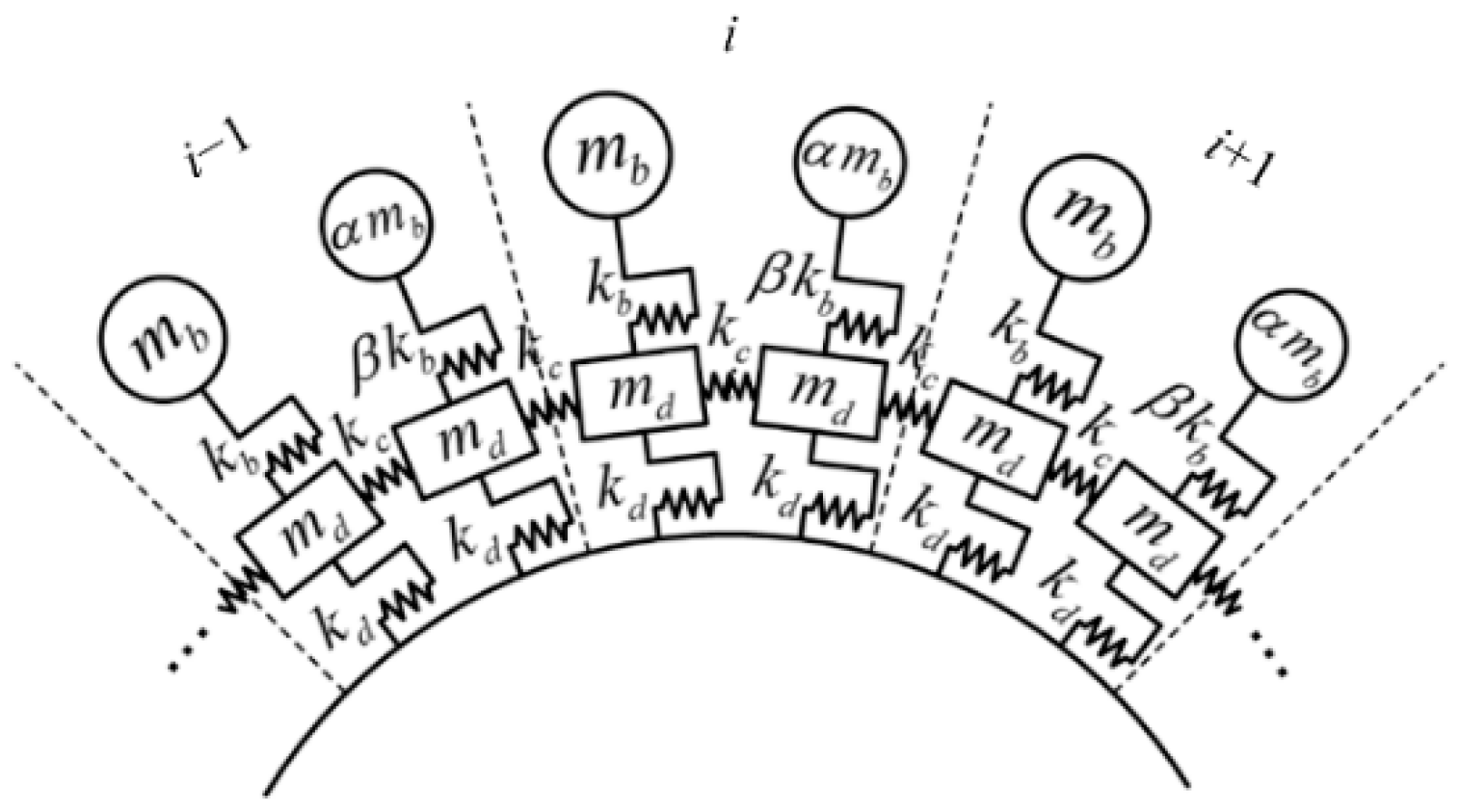
2.1. Lumped Parameter Model of the Impeller with Splitter Blades
In order to more explicitly reveal the influence of splitter blades on the resonance conditions, a lumped parameter model of the impeller is established as shown in Figure 1. Modal analysis is performed and the undamped equation of motion (EoM) of the i-th sector is given as Equation (1):
in which , , and represent masses of the main blade, the splitter blade, and the disk part, respectively, and represent the displacements of the main blade and the splitter blade, and correspond the two disk parts, and are the stiffnesses of the main and the splitter blade, is the coupling stiffness. Unlike the conventionally designed impellers which contain only one blade per sector, the impellers with splitters usually contain one main blade and one splitter blade per sector.
Figure 1.
Lumped parameter model of the impeller with splitter blades.
Rewrite Equation (1) in matrix form
and the nondimensional EoM of the -sector impeller can be written as
Related properties of circulant matrices are utilized to solve the EoM [34]. Transformation of coordinates is introduced as
in which represents the direct product (or Kronecker product), is Fourier matrix as shown in Equation (5) in which , and is the unit matrix.
The original EoM is block decoupled by substituting Equation (4) into Equation (3) and multiplying from the left by . Hence, the eigen equation of the decoupled EoM is written as
and the nondimensional natural frequency of the -th mode of nodal diameter (ND) and its corresponding eigenvector can be obtained, , . Due to the symmetry characteristics of the eigenvalue and eigenvector structure of the cyclic symmetric structures [34], only the circumstance of needs to be discussed, in which denotes floor function.
Partition the eigenvector into the blade part and the disk part as shown in Equation (7) and the blade mode shape for the -th mode of ND can be written in the physical coordinate as Equation (8)
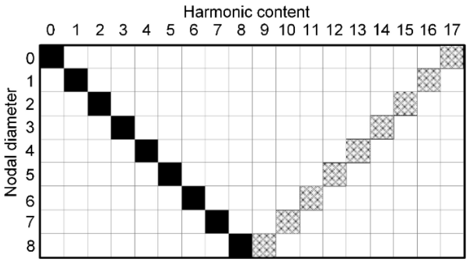
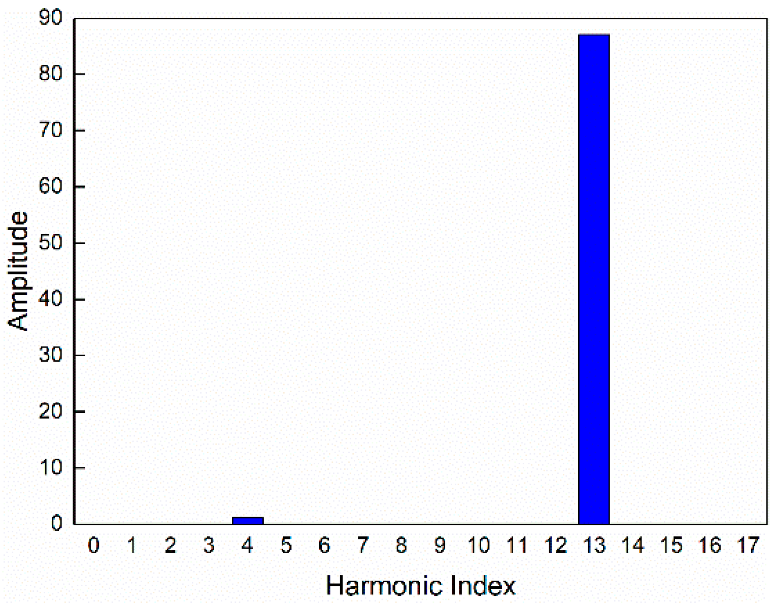
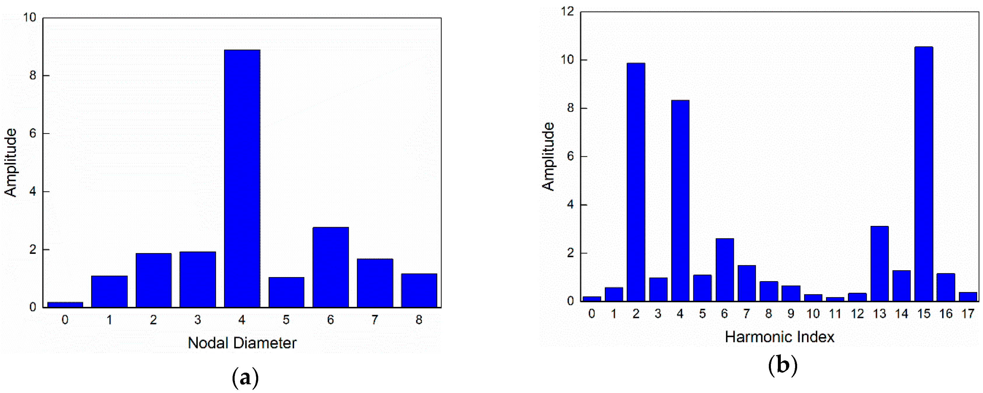
2.2. Spatial Harmonic Contents Analysis to the RMV
The natural mode shape of the impeller needs to be matched with the harmonic excitation periodic shape, which is the necessary condition for the resonance of the impeller [23]. Therefore, after the modal analysis, a blade-based RMV is defined with the influence of splitter blades taken into consideration and the spatial harmonic contents analysis is performed to it in order to make clear the spatial distribution of the mode shape.
As for cyclic symmetric structures like impellers, the mode shape can be described based on the duplicated sector and the pattern of displacement formed by all sectors is similar to a harmonic wave [35]. Thus, the vector formed by modal displacements of nodes with the same relative position of the sector is also spatially sinusoidal, which is guaranteed by the cyclic symmetry properties. This kind of vector reflects the impeller’s traits of modes to some extent, so we name it RMV. The simplest and the most common way to form the RMV is to extract the displacement at a node at the tip of the blades [36,37,38]. When performing the discrete Fourier transform (DFT) of the RMV, the harmonic component is nonzero only at the wavenumber index of the corresponding harmonic wave [36].
As for impellers with splitter blades, each sector includes one main blade and one splitter blade. If the RMV is extracted based on structural cyclic symmetric property in the same way as the conventionally designed impellers, for example, extracting the displacement at a node at the tip of the main (or splitter) blades, the cyclic symmetry of the mode shape is indeed reflected; however, the influence of splitter (or main) blades on the whole impeller’s traits of modes are ignored. Therefore, to guarantee that the whole structure’s traits of modes are reflected adequately, the influence of splitter blades must be taken into account. Namely, the displacements should be extracted from all main and splitter blades to form the blade-based RMV. For example, is the blade-based RMV for the model as shown in Figure 1. Then, the spatial harmonic contents analysis is performed on it.
Denote as the DFT sinusoid matrix then the DFT of can be represented as Equation (9).
Partition into real and imaginary parts:
Then the DFT result can be rewritten as Equation (12)
in which
The ()th and the th element in and are written as Equations (14) and (15), .
The obtained by DFT is a real vector as shown in Equation (16), in which the elements distribute symmetrically around the center of the ()th element except for the first element. Thus, only the first elements are discussed here due to their independence.
When the number of sectors is even, only the circumstances of need to be discussed, which correspond to the ND modes. Further, when , only the th and the ()th ones of the first elements are nonzero and the rest are all zeros because they are independent of or , which can be calculated by Equations (14) and (15). The only two nonzero elements and correspond to the th harmonic and th harmonic, in which and . Obviously,
When , here is the same situation that only the th and the (th element of are nonzero.
When the number of sectors is odd, only the circumstances of need to be discussed which correspond to the ND modes. The same results can be reached. The details are omitted for the sake of brevity.
The above analysis shows that the RMV of the tuned impeller with splitter blades contains two harmonic components rather than one. This is due to the existence of the splitter blades. In addition, it is also found that the order of the th harmonic is equal to the nodal diameter index of the mode, so that the order of the th harmonic can be obtained by Equation (18) as well.
in which, denotes the nodal dimeter index.
2.3. Simplified Diffuser-Induced Engine Order Excitation
The excitation generated from the impeller–diffuser interaction is the main excitation acting on the impeller. The excitation frequency is proportional to the engine speed and the spatial nature of the excitation is in the form of a traveling wave [17,39]. The unsteady force generated from the interaction is mainly acting near the trailing edges of blades [25,27]. According to the Fourier analysis of the static pressure distribution at the impeller exit, the first harmonic pressure is dominant and the higher order pressures attenuate rapidly [40]. Thus, we can only use the first harmonic pressure in forced response calculation as a kind of simplification [27,41]. Unlike the conventionally designed impellers, the amplitude of the aerodynamic force acting on the main blades is usually higher than that on the splitter blades [25,26,27].
Suppose the th blade and the ()th blade represent the main blade and the splitter blade of the th sector, respectively, then the aerodynamic force acting on them can be written in the following form:
in which, and are amplitudes, is the engine order of excitation, is rotating speed of the impeller, and is sector index and all blades are equally spaced by the angle .
2.4. Resonance Conditions of Impellers with Splitter Blades
When the work done by the unsteady aerodynamic forces acting on the impeller is greater than zero after one cycle of the main harmonic, the resonance is excited, which leads to an increasing vibration amplitude. The resonance conditions will be derived based on this.
From Section 2.2, we have already known that the RMV obtained based on all blades contains two harmonic contents. Thus, the displacement of the -th blade can be written as
in which and are the amplitudes of the corresponding -th and -th harmonic components respectively, and are generic phases for the time and the angle variables.
The speed of the -th blade can be obtained as the partial derivative of the displacement with respect to time as shown in Equation (21), in which is the generic phase angle.
The work done to the whole impeller is
which is equal to the sum of the work done to each sector. The work done to the -th sector is written as
in which
Similar to Bertini et al.’s research [42], the above equation yields the following results
Considering the physical meaning of the excitation order, has to be positive. Thus, Equation (26) is rewritten as
in which is taken as or .
Equations (25) and (27) constitute the resonance conditions of impellers with splitter blades. They indicate that only when the excitation frequency equals the natural frequency and the excitation order matches either harmonic index of the two harmonics, can the resonance occur.
Due to the existence of the splitter blades, the blade-based RMV of the impeller contains two harmonic components and the amplitudes of the two harmonics are usually different. This indicates that the excitations corresponding to the different harmonic components will lead to the different resonance states even for the same mode, e.g., the excitation corresponding to the dominant harmonic may arouse a larger resonant response. Numerical examples of the application of the proposed resonance conditions are given in the following section.
3. Numerical Analysis
Resonance conditions are not only used for judging whether the resonance occurs, but also can be utilized to determine the dangerous engine orders of excitation which can arouse the resonance of the target mode. Especially when mistuning is considered, the harmonic contents of a mode become more complex compared with the tuned mode, which makes more excitations of different engine orders capable of arousing the resonance of the impeller [36,37]. In this situation, engine orders of these excitations need to be determined and the harmfulness of these excitations needs to be evaluated. Determination of the dangerous engine order of excitation helps to choose the appropriate number of vanes to avoid the resonance in advance.
In this section, two cases are provided. In the tuned case, the proposed resonance conditions are used for identifying the resonance of a practical impeller and the identification based on the conventional resonance conditions are also provided as a comparison. In the mistuned case, the engine orders of excitation which can arouse the resonance of the target mode are determined by the proposed resonance conditions and the conventional ones, respectively. Further, hazard evaluation is conducted for the excitations of various engine orders.
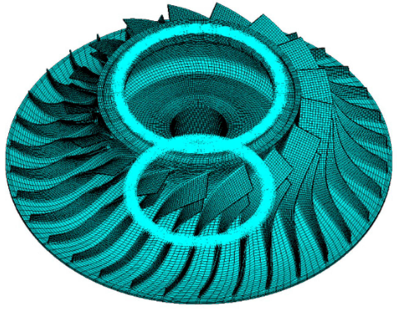
3.1. Description of the Model
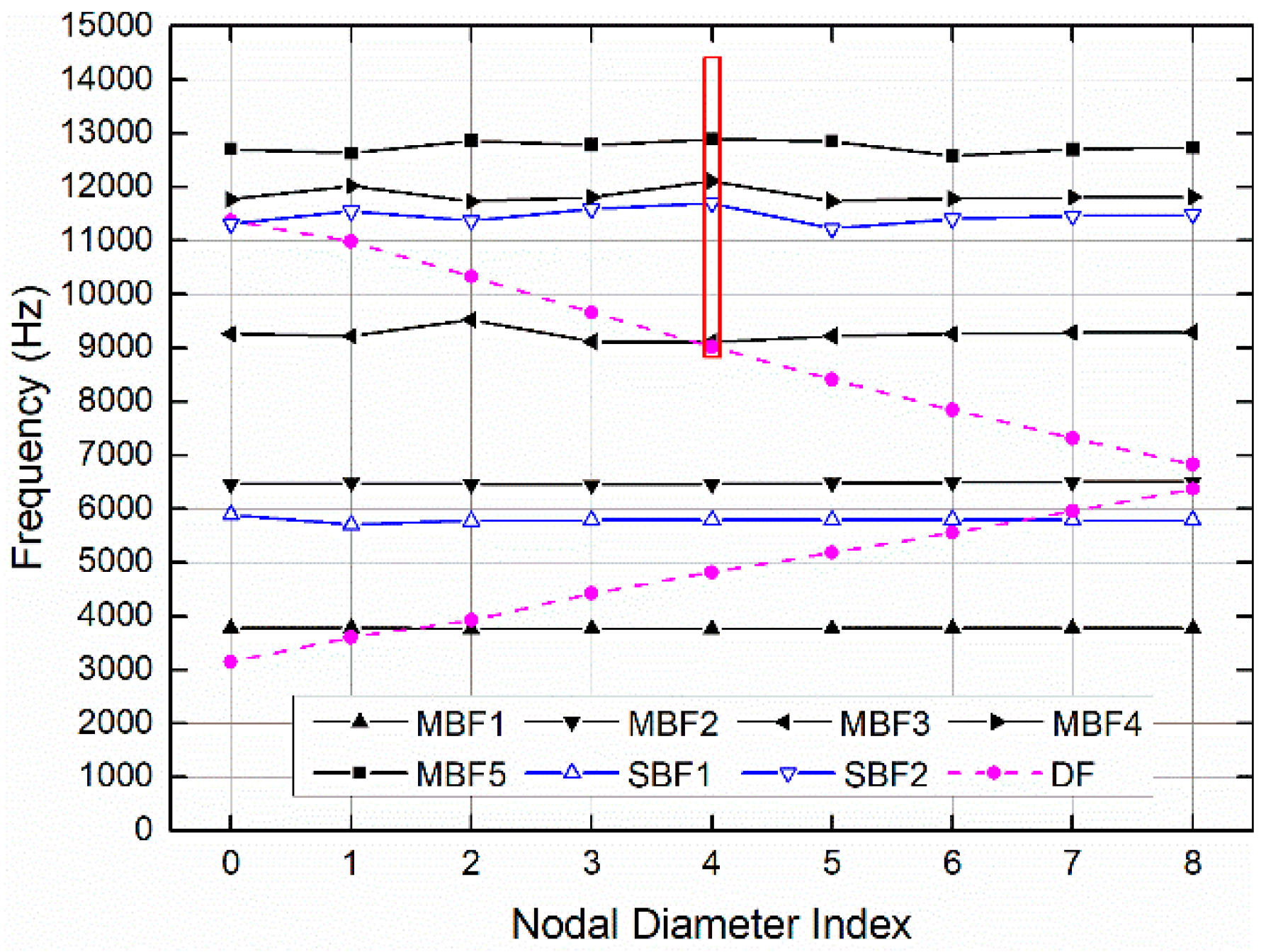
The prototype centrifugal compressor is comprised of two parts: the impeller and the vaned diffuser. The impeller features 17 main blades and 17 splitter blades. The inlet diameter and the outlet diameter are about 165 mm and 310 mm, respectively. The blade heights are about 25 mm and 10 mm at the inlet and outlet of the impeller. The material properties used for the whole impeller are those of titanium (, , ). For this study, the finite element model of the impeller is established in the commercial package ANSYS Mechanical (Version 15.0 64-bit; ANSYS: Canonsburg, PA, USA, 2015) [43]. Additionally, the subsequent modal analysis and harmonic response analysis are performed in ANSYS Mechanical. The model is meshed with the eight-node hexahedral element, i.e., SOLID185 element type in ANSYS, as shown in Figure 2. The front bore of the impeller is constrained circumferentially and the rear bore is constrained axially. The mesh dependency is checked with three mesh models of different mesh density and the result is shown in Table 1. The first 200 frequencies are calculated for these models. Compared with mesh model III, the average frequency error is about 0.71% and 0.01% for the mesh model I and mesh model II, respectively. Considering that the main purpose of the numerical examples is to validate that the proposed resonance conditions and stress calculation are not of concern, mesh model II is employed with sufficient accuracy for modal characteristics.
Figure 2.
Finite element model of the impeller.
Table 1.
Mesh dependency check result.
As for the vaned diffuser, there are two different configurations, corresponding to the number of vanes of 19 and 21. Both designs can meet the aerodynamic performance requirements. In Section 4.2, the significance of the proposed resonance conditions in guiding the compressor design by choosing an appropriate number of vanes will be illustrated.
3.2. Tuned Case
In this case, the analysis processes of identifying the potential resonance of the tuned impeller by the conventional resonance conditions and the proposed resonance conditions are given, respectively. The analysis process is independent with regard to the number of diffuser vanes, so only the configuration of the 21-vaned diffuser is used for illustration.
3.2.1. Resonance Identification by Conventional Resonance Conditions
Modal analysis of the impeller is carried out. The simplified Singh’s advanced frequency evaluation (SAFE) diagram [17] is shown in Figure 3. The first five main blade dominated mode families MBF1~MBF5 are connected by black solid lines and the first two splitter blade dominated mode families SBF1~SBF2 are connected by blue solid lines. The disk dominated mode families DF are connected by pink dashed lines. Some mixed modes are omitted for clarity.
Figure 3.
The simplified Singh’s advanced frequency evaluation (SAFE) diagram.
In the conventional resonance conditions, the frequency matching condition and the shape matching condition can be written as Equations (28) and (29), respectively, in which is the excitation frequency, is the natural frequency of the impeller, is the engine order of excitation, which usually takes the number of vanes or struts, is the number of sectors, is the nodal diameter index, and could be any integer.
From Equation (29), we know that the excitation generated from 21 vanes is capable of arousing the resonances of the ND4 modes. Thus, some of the ND4 modes are marked in the red box as shown in Figure 3, which are likely to encounter resonances. The bottom and top of the box represent the lower and upper bound of the excitation frequency, which is limited by the operating range of engine speed. Because the excitation frequency corresponding to the idle engine speed is very close to the natural frequency of mode 94, mode 94 is chosen as the dangerous mode for further analysis. The mode shape is shown in Figure 4. The deformation mainly occurred in the outer regions around the disk, the axial component of which is prominent. Besides, 13 nodal lines are obvious from the back view of the mode shape.
Figure 4.
(a) Front view of mode shape of mode 94; (b) Back view of mode shape of mode 94.
According to the conventional resonance condition (Equation (29)), the ND4 modes can only be aroused resonances by the excitations with . Therefore, the engine order excitation caused by the 21-vaned diffuser can arouse the resonance of mode 94. In addition, from previous studies we know that for the excitations with , the resultant resonant amplitudes are all the same [23].
3.2.2. Resonance Identification by the Proposed Resonance Conditions
From Section 2, we know that after the spatial harmonic content analysis of the target mode, the resonance of the impeller with splitter blades can be identified by the proposed resonance conditions.
As for the 17-sector impeller used here, the relationship between the nodal diameter index and the harmonic index for a vibration mode is shown in Figure 5, which is obtained by Equation (17). It indicates the harmonic contents of mode 94 contain the 4th harmonic and the 13th harmonic. In order to clearly get the respective contribution of mode 94, spatial harmonic contents analysis of the blade-based RMV is required.
Figure 5.
Relationship between nodal diameter index and harmonic content for a 17-sector impeller with splitter blades.
In Section 2.2, the blade-based RMV is extracted from the degrees of freedom of blades. This is easily obtained by the lumped parameter model. As for the prototype impeller shown in Figure 2, the blade-based RMV can be formed by the axial modal displacements extracted from nodes with relatively similar positions on all blades’ trailing edge regions. Here, the trailing edge nodes of all blades’ tips are used for sampling. This is based on the following considerations: (1) the main and splitter blades have identical geometric characteristics in the trailing edge regions; (2) the diffuser-induced excitations mainly act near the impeller exit; (3) for the typical mode shape of impellers, the axial vibration at the outer regions of the impeller manifests as mode 94.
The harmonic contents analysis is performed on the blade-based RMV and the result is shown in Figure 6. It indicates the 13th harmonic is apparently dominant and the 4th harmonic, in contrast, is negligible. That is exactly why the ND4 mode exhibits 13 nodal lines.
Figure 6.
Harmonic content of the RMV of mode 94.
According to the proposed resonance condition (Equation (27)), we know the 13th harmonic component of the mode can be excited by the excitations with and the 4th harmonic component can be excited by the excitations with . Thus, the excitation generated from 21 vanes can arouse the resonance of mode 94 by exciting the 13th harmonic component. Additionally, due to the higher amplitude of the 13th harmonic component, we conclude that the resonant amplitude aroused by the excitations with should be larger.
3.3. Mistuned Case
In this case, the dangerous excitations of the target mistuned mode are determined by the proposed resonance conditions and the conventional ones, respectively. Further, the harmfulness of these excitations is evaluated.
3.3.1. Mistuning Parameter
Suppose the random blade mistunings are distributed uniformly with zero mean and 3% standard deviation for main blades and 1% standard deviation for splitter blades. The random mistuning pattern is shown in Table 2.
Table 2.
Random mistuning pattern ().
In the finite element model of the impeller, as shown in Figure 2, the mistuning is introduced by modification of the Young’s modulus of each blade. The mistuned elasticity modulus of the th blade of the th sector can be expressed as:
where denotes the tuned elastic modulus and denotes the relative deviation of the th blade of the th sector.
3.3.2. Hazard Evaluation for Excitations of Various Engine Orders
Here, mode 192 is chosen as the target mistuned mode for the following analysis. It corresponds to the ND4 mode in MBF5.
When evaluating the harmfulness of the excitations with various engine orders in the conventional way, the ND components need to be analyzed for the mistuned mode first. Then, the engine orders of excitation corresponding to these ND components can be determined by the conventional resonance conditions using Equation (29). After that, the harmfulness of these excitations can be ranked based on the corresponding amplitudes of the ND components [36,37]. Here, the nodal diameter spectrum method proposed by Yao et al. is used to analyze the ND contents of the mistuned mode 192 and the result is shown in Figure 7a. The ND components are sorted by amplitudes in descending order: ND4, ND6, and ND3. According to Equation (29), the engine orders of excitation which can arouse the corresponding ND components are , and , respectively. Thus, the harmfulness of these excitations can be ranked as follows: , , and .
Figure 7.
(a) Nodal diameter spectrum of the mistuned mode 192; (b) Harmonic content of the RMV of the mistuned mode 192.
According to Section 2, the evaluating process is now conducted as follows: first analyze the harmonic contents of the target mistuned mode. This can be done by performing spatial harmonic content analysis of the blade-based RMV. Then, determine the engine orders of excitation based on the proposed resonance condition using Equation (27). After that, rank the harmfulness of these excitations according to the corresponding amplitudes of the harmonic components. The spatial harmonic contents analysis result is shown in Figure 7b and the largest three harmonics are: , , and . According to Equation (27), the corresponding engine orders are , and respectively. Thus, the harmfulness of these excitations can be ranked as follows: , , and .
Obviously, different evaluation results are obtained. To validate the proposed resonance conditions and the evaluation results, harmonic response analysis is performed in the following section.
4. Validation and Discussion
Harmonic responses under the excitations of various engine orders are calculated for both the tuned and mistuned cases. From that, the validity of the proposed resonance conditions is verified. Then, the differences of the results obtained based on the proposed resonance conditions and the conventional ones are analyzed. Moreover, the significance of the proposed resonance conditions in guiding the compressor design is illustrated. Finally, the differences between the proposed resonance conditions and the conventional ones are discussed.
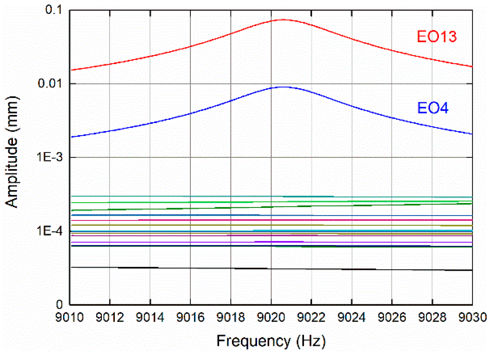
4.1. Harmonic Response Calculation
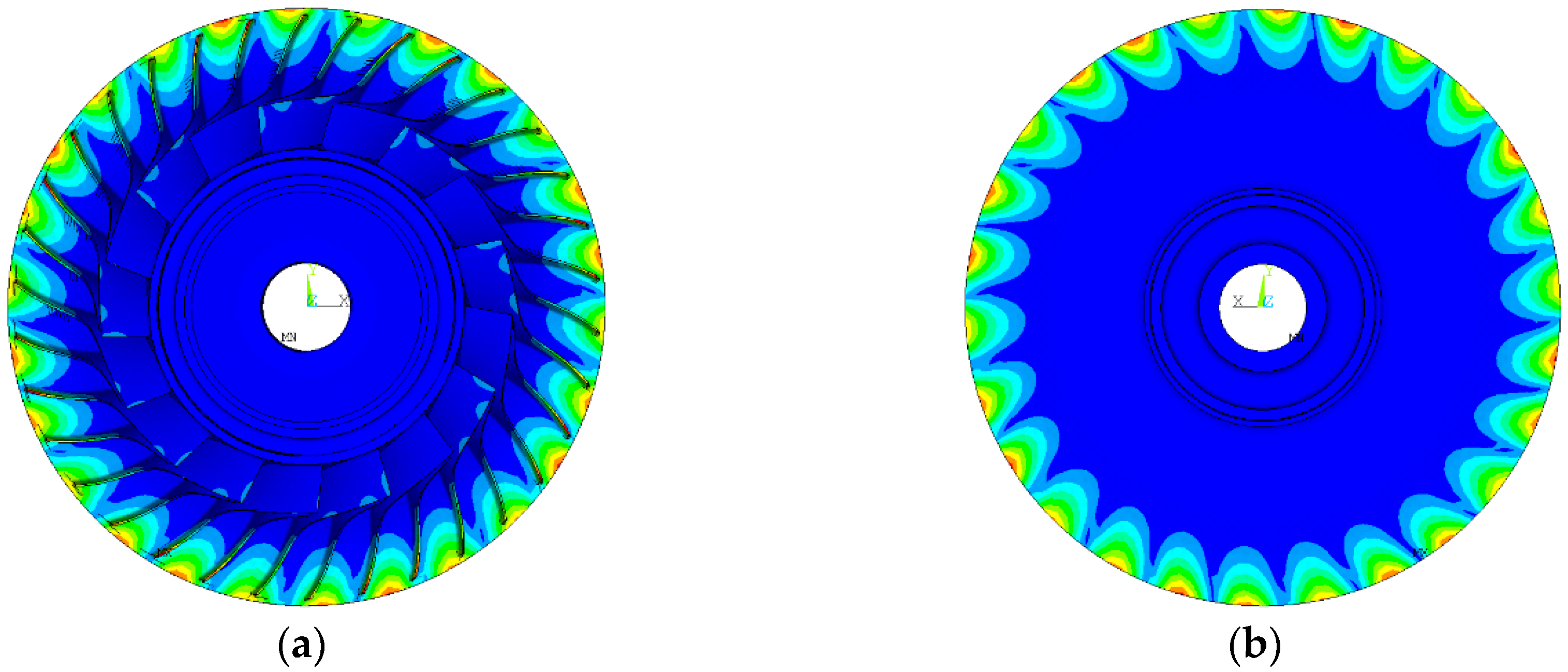
During the harmonic response analysis, the form of the excitation is that of Equation (19). The amplitudes of the exciting forces are taken as 1 N and 0.8 N for the main blades and splitter blades, respectively. The structural damping in the harmonic response calculation is set as 0.005. Due to the effect of aliasing, the excitation order only takes from EO1 to EO17 [23].
4.2. Tuned Results
The tuned harmonic response results are shown in Figure 8. It can be seen that only the excitation of the engine orders satisfying Equation (27) (e.g., EO13, EO4) aroused the resonances of the impeller. Moreover, the excitation with the engine order corresponding to the dominant harmonic component, EO13, aroused the larger resonant response of 0.0737 mm, while the response aroused by EO4 is only 0.00907 mm. The other excitations except EO13 and EO4 failed to arouse resonance with response amplitude under 6 × 10⁻⁵ mm.
Figure 8.
Amplitude–frequency response curves under EO1–EO17.
The tuned harmonic response results confirm that the resonance of the impeller can be effectively identified by the proposed resonance conditions. Furthermore, the excitations of various engine orders can be further distinguished based on the spatial harmonic content, which is reflected from the amplitude of the th harmonic component in the proposed resonance condition via Equation (27). Indeed, the resonance can also be detected by the conventional resonance conditions; however, these excitations cannot be distinguished in the conventional resonance conditions.
4.3. Mistuned Results
The mistuned harmonic response results are shown in Figure 9a. It can be seen that the engine orders of excitation corresponding to the largest three response amplitudes are , , and . This means the most harmful excitations are the excitations of , , and respectively, which is in line with the evaluation results obtained based on the proposed resonance conditions in Section 3.3.2. Moreover, the maximum response amplitude of each excitation and the amplitude of each harmonic component are all normalized and compared in Figure 9b. It shows the variation trends are almost the same.
Figure 9.
(a) Mistuned response under EO1–EO17; (b) Comparison of normalized harmonic content amplitude of mistuned mode 192 and normalized mistuned response amplitude under EO1–EO17.
Once again, it has been proved by the mistuned case that the resonance can be effectively identified by the proposed resonance conditions. More importantly, the results above indicate that when analyzing the harmonic content of a mistuned mode for impellers with splitter blades, the RMV should be extracted based on all blades rather than sectors. Analyzing in the conventional way may lead to the misjudgment of the harmfulness of the excitations.
4.4. Significance in Guiding the Compressor Design
As mentioned earlier, there are two configurations for the vaned diffuser: the 19-vane diffuser and the 21-vane diffuser. As for the mistuned mode with this specific mistuning pattern, the result of the hazard evaluation for the excitations of various engine orders can serve as a guide for choosing a more appropriate number of diffuser vanes. For example, the excitation of EO21, which corresponds to the 21-vaned diffuser configuration, is capable of exciting the 13th harmonic component of the mode. The excitation of EO19, which corresponds to the 19-vaned diffuser configuration, is capable of exciting the 15th harmonic component of the mode. From the mistuned harmonic response result, we have found that the excitation of EO19 is more harmful than the excitation of EO21. Therefore, the 21-vaned diffuser configuration is the better choice when only considering this particular mistuned mode. It should be pointed out that the matching between the impeller and diffuser is a complex process which involves effort from both the aerodynamic side and structural side. So, the example here is only used to illustrate the significance of the proposed resonance conditions in guiding compressor design.
In addition, as a means of vibration reduction, intentional mistuning has been studied and gradually applied to the conventionally designed bladed structures [38,44]. The mechanism of it is to change the harmonic contents of the certain modes by introducing a special form of mistuning and thus to change the excitability of the determined excitation of these modes [37]. This indicates that the harmonic content of a mode must be determined when designing the intentional mistuning. From the research above, we know that as for impellers with splitter blades, the harmonic contents can be determined with the help of the concept of the blade-based RMV and the resonance can be identified by the proposed resonance conditions.
4.5. Differences from the Conventional Resonance Conditions
The differences between the proposed resonance conditions and the conventional ones are caused by the existence of splitter blades, which are reflected in the following points:
- The proposed resonance conditions are derived based on the impellers with splitter blades. The influences of splitter blades on the natural structural characteristics and excitation characteristics are taken into consideration. However, the conventional resonance conditions are derived based on the conventionally designed impellers without considering the splitter blades.
- The shape matching condition of the proposed resonance conditions is dependent with the total number of main and splitter blades, i.e., in Equation (27). For the conventional shape matching condition, it is dependent on the number of sectors, i.e., in Equation (29).
- The proposed shape matching condition is also dependent with the harmonic contents of the mode, i.e., in Equation (27), which are analyzed based on the blade-based RMV. For the conventional shape matching condition, it is related to the nodal diameter component in Equation (29), which is analyzed based on the duplicated sector by cyclic symmetry.
5. Conclusions
In this paper, the resonance conditions for impellers with splitter blades under the excitation from the impeller–diffuser interaction are proposed. The influence of splitter blades on the resonance conditions is investigated analytically and numerically. The applications of the proposed resonance conditions in identification of the potential resonances, determination of the dangerous engine order of excitation, and the hazard evaluation for excitations with various engine orders are illustrated in the tuned and mistuned cases. Moreover, the significance of the proposed resonance conditions in guiding the compressor design by choosing an appropriate number of vanes is discussed. The potential of the proposed resonance conditions in designing the intentional mistuning is also pointed out. Some main conclusions obtained from the current work are as follows:
- A lumped parameter model of the impeller with splitter blades is established for the first time. For describing the traits of the impeller’s modes adequately, the RMV should be extracted based on all main and splitter blades rather than sectors, i.e., the blade-based RMV should be used.
- The blade-based RMV of a tuned mode contains two harmonic components due to the existence of the splitter blades. For the conventionally designed impellers, the RMV of a tuned mode contains only one harmonic component.
- The proposed resonance conditions consist of two terms: (1) the excitation frequency equals the natural frequency of the impeller; (2) the excitation order matches either harmonic index of the two harmonics. When both terms are simultaneously satisfied, resonance occurs.
- The potential resonance can be effectively identified by the proposed resonance conditions. It also indicates that different resonance states of the impeller can be reached even for the same tuned mode. This is due to the different amplitudes of the harmonic components of a mode, which is reflected by the different values of in the proposed resonance conditions. However, the conventional resonance conditions contain no information on this.
- The harmfulness of different excitations with various engine orders can be evaluated accurately by the joint use of the spatial harmonic analysis result and the proposed resonance conditions. Analyzing based on the conventional resonance conditions may lead to the misjudgment of the harmfulness of different excitations. So, when evaluating the harmfulness of the excitations with various engine orders for mistuned impellers, the proposed resonance conditions should be used instead of the conventional ones.
Author Contributions
Conceptualization, K.L.; Methodology, K.L. and C.Y.; Software, K.L.; Validation, K.L. and C.Y.; Formal analysis, K.L. and C.Y.; Investigation, K.L.; Resources, K.L.; Data curation, K.L.; Writing—original draft preparation, K.L.; Writing—review and editing, C.Y.; Visualization, K.L. and C.Y.; Supervision, C.Y.; Project administration, K.L.
Funding
This research received no external funding.
Conflicts of Interest
The authors declare no conflict of interest.
Nomenclature
| Amplitude of the th harmonic component | |
| Amplitude of the th harmonic component | |
| Fourier matrix | |
| Mistuned elasticity modulus of the th blade of the th sector | |
| Tuned elastic modulus | |
| Force amplitude of the main blade | |
| Force amplitude of the splitter blade | |
| Force acting on the jth blade | |
| Harmonic component | |
| unit matrix | |
| Stiffness matrix of the system | |
| Any integer | |
| Blade stiffness | |
| Coupling stiffness | |
| Disk stiffness | |
| Mass matrix of the system | |
| Blade mass | |
| Disk mass | |
| Number of duplicated sectors | |
| Engine order of excitation | |
| Nodal diameter index | |
| DFT of | |
| Physical displacement vector of the system | |
| Displacement of the main blade of the ith sector | |
| Displacement of the splitter blade of the ith sector | |
| Displacement of the disk part corresponding to the main blade of the ith sector | |
| Displacement of the disk part corresponding to the splitter blade of the ith sector | |
| Blade mode shape for the th mode of ND | |
| Blade part of modal displacement vector | |
| Modal displacement vector of the system | |
| Modal displacement vector of the -th mode of ND | |
| Speed of the th blade | |
| Work done to the whole impeller | |
| Work done to the ith sector | |
| DFT sinusoid matrix | |
| Primitive Nth roots of unity | |
| Displacement of the th blade | |
| Greek Symbols | |
| Mass coefficient for splitter blade | |
| Stiffness coefficient for splitter blade | |
| Relative deviation of the th blade of the th sector | |
| Angular spacing of the blades | |
| Mean value of the uniform distribution | |
| Standard Deviation of the uniform distribution | |
| Generic phase for the angle variable | |
| Generic phase angle | |
| Generic phase for the time variable | |
| Rotating speed of the impeller | |
| Excitation frequency | |
| Natural frequency of the impeller | |
| Abbreviations | |
| EO | Engine Order |
| EoM | Equation of Motion |
| DF | Disk Dominated Mode Family |
| DFT | Discrete Fourier Transform |
| HCF | High Cycle Fatigue |
| MBF | Main Blade Dominated Mode Family |
| ND | Nodal Diameter |
| RMV | Representative Modal Vector |
| SAFE | Singh’s Advanced Frequency Evaluation |
| SBF | Splitter Blade Dominated Mode Family |
References
- Krain, H. Review of Centrifugal Compressor’s Application and Development. J. Turbomach. 2005, 127, 25–34. [Google Scholar] [CrossRef]
- Zheng, X.; Zhang, Y.; Yang, M. Research and Development on Transonic Compressor of High Pressure Ratio Turbocharger for Vehicle Internal Combustion Engines. Sci. China Technol. Sci. 2010, 53, 1817–1823. [Google Scholar] [CrossRef]
- Wang, Y.; Shi, D.; Zhang, D.; Xie, Y. Investigation on Unsteady Flow Characteristics of a SCO2 Centrifugal Compressor. Appl. Sci. 2017, 7, 310. [Google Scholar] [CrossRef]
- Ye, L.; Yuan, S.; Zhang, J.; Yuan, Y. Effects of Splitter Blades on the Unsteady Flow of a Centrifugal Pump. In Volume 1: Symposia, Parts A and B, ASME 2012 Fluids Engineering Summer Meeting, Rio Grande, Puerto Rico, USA, 8–12 July 2012; ASME: New York, NY, USA, 2012; pp. 435–441. [Google Scholar]
- Xu, C.; Amano, R.S. Empirical Design Consideration for Industrial Centrifugal Compressors. Int. J. Rotating Mach. 2012, 2012, 184061. [Google Scholar] [CrossRef]
- Xu, C.; Amano, R.S. Meridional Considerations of the Centrifugal Compressor Development. Int. J. Rotating Mach. 2012, 2012, 518381. [Google Scholar] [CrossRef]
- Mojaddam, M.; Pullen, K.R. Optimization of a Centrifugal Compressor Using the Design of Experiment Technique. Appl. Sci. 2019, 9, 291. [Google Scholar] [CrossRef]
- Wang, S.; Zi, Y.; Wan, Z.; Li, B.; He, Z. Effects of Multiple Cracks on the Forced Response of Centrifugal Impellers. Mech. Syst. Signal Process. 2015, 60–61, 326–343. [Google Scholar] [CrossRef]
- Zemp, A.; Abhari, R.S.; Schleer, M. Experimental Investigation of Forced Response Impeller Blade Vibration in a Centrifugal Compressor with Variable Inlet Guide Vanes: Part 2—Forcing Function and FSI Computations. In Volume 6: Structures and Dynamics, Part A and B, ASME Turbo Expo 2011: Turbine Technical Conference and Exposition, Vancouver, BC, Canada, 6–10 June 2011; ASME: New York, NY, USA, 2011; pp. 1381–1392. [Google Scholar]
- Zhang, X.; Zhao, W.; Xie, Y. Fatigue Failure Analysis of Semi-Open Impeller with Mistuning Considered. Eng. Fail. Anal. 2019, 95, 127–139. [Google Scholar] [CrossRef]
- Zhang, M.; Liu, Y.; Wang, W.Q.; Wang, P.F.; Li, J.F. The Fatigue of Impellers and Blades. Eng. Fail. Anal. 2016, 62, 208–231. [Google Scholar] [CrossRef]
- Chen, X.; Xu, S.; Wang, X.; Ju, W.; Yang, S.; Meng, J. Research on Failure of Semi-Open Centrifugal Impeller under Aerodynamic Load. In Volume 7B: Structures and Dynamics ASME Turbo Expo 2017: Turbomachinery Technical Conference and Exposition, Charlotte, NC, USA, 26–30 June 2017; ASME: New York, NY, USA, 2017; p. V07BT36A017. [Google Scholar]
- Robinson, C.; Casey, M.; Hutchinson, B.; Steed, R. Impeller–Diffuser Interaction in Centrifugal Compressors. In Volume 8: Turbomachinery, Parts A, B, and C, ASME Turbo Expo 2012: Turbine Technical Conference and Exposition, Copenhagen, Denmark, 11–15 June 2012; ASME: New York, NY, USA, 2012; pp. 767–777. [Google Scholar]
- Hosseini, M.; Sun, Z.; He, X.; Zheng, X. Effects of Radial Gap Ratio Between Impeller and Vaned Diffuser on Performance of Centrifugal Compressors. Appl. Sci. 2017, 7, 728. [Google Scholar] [CrossRef]
- Artetxe, E.; Olvera, D.; Lopez de Lacalle, L.N.; Campa, F.J.; Olvera, D.; Lamikiz, A. Solid Subtraction Model for the Surface Topography Prediction in Frank Milling of Thin-Walled Integral Blade Rotors (IBRs). Int. J. Adv. Manuf. Technol. 2017, 90, 741–752. [Google Scholar] [CrossRef]
- Calleja, A.; Alonso, M.A.; Fernandez, A.; Tabernero, I.; Ayesta, I.; Lamikiz, A.; Lopez de Lacalle, L.N. Frank Milling Model for Tool Path Programming of Turbine Blisks and Compressors. Int. J. Prod. Res. 2015, 53, 3354–3369. [Google Scholar] [CrossRef]
- Walton, E.J.; Tan, C.S. Forced Response of a Centrifugal Compressor Stage Due to the Impeller–Diffuser Interaction. J. Turbomach. 2016, 138, 9100491–91004913. [Google Scholar] [CrossRef]
- Zemp, A.; Abhari, R.S. Vaned Diffuser Induced Impeller Blade Vibrations in a High-Speed Centrifugal Compressor. J. Turbomach. 2013, 135, 210151–210159. [Google Scholar] [CrossRef]
- Lerche, A.H.; Moore, J.J.; White, N.M.; Hardin, J. Dynamic Stress Prediction in Centrifugal Compressor Blades Using Fluid Structure Interaction. In Volume 6: Oil and Gas Applications, Concentrating Solar Power Plants; Steam Turbines, Wind Energy ASME Turbo Expo 2012: Turbine Technical Conference and Exposition, Copenhagen, Denmark, 11–15 June 2012; ASME: New York, NY, USA, 2012; pp. 191–200. [Google Scholar]
- Mao, Y.J.; Qi, D.T.; Xu, Q.Y. Fatigue Analysis and Lifetime Estimation of Centrifugal Compressor Impeller Blades. In Proceedings of the ASME Expo 2009: Power for Land, Sea and Air, Orlando, FA, USA, 8–12 June 2009; ASME: New York, NY, USA, 2009; pp. 83–91. [Google Scholar]
- Ferioli, M. The Use of Interference Diagrams to Avoid Impeller Resonance: An Application to IGV Design. In Volume 4: 7th International Conference on Multibody Systems, Nonlinear Dynamics, and Control, Parts A, B and C, ASME 2009 International Design Engineering Technical Conferences & Computers and Information in Engineering Conference, San Diego, CA, USA, 30 August–2 September 2009; ASME: New York, NY, USA, 2009; pp. 755–762. [Google Scholar]
- Kushner, F. Rotating Component Modal Analysis and Resonance Avoidance Recommendations. In Proceedings of the Thirty-Third Turbomachinery Symposium, Houston, TX, USA, 20–23 September 2004. [Google Scholar]
- Singh, M.P.; Thakur, B.K.; Sullivan, W.B.; Donald, G. Resonance Identification for Impellers. In Proceedings of the Thirty-Second Turbomachinery Symposium, Houston, TX, USA, 8–11 September 2003. [Google Scholar]
- Wang, Q.; Bartos, J.C.; Houston, R.A. Methodology of Open Bladed Impeller Resonance Identification. In Proceedings of the Twenty-Eighth Turbomachinery Symposium, Houston, TX, USA, 14–16 September 1999. [Google Scholar]
- Smythe, C.J. Forced Response Predictions in Modern Centrifugal Compressor Design. Master’s Thesis, Massachusetts Institute of Technology, Cambridge, UK, 2005. [Google Scholar]
- Liu, B.; Zhang, B.; Liu, Y. Numerical Investigations of Impeller–Diffuser Interactions in a Transonic Centrifugal Compressor Stage Using Nonlinear Harmonic Method. Proc. Inst. Mech. Eng. Part A J. Power Energy 2014, 228, 862–877. [Google Scholar] [CrossRef]
- Ramakrishnan, K.; Lawless, P.B.; Fleeter, S. High Speed Centrifugal Compressor Aeromechanics—Impeller Unsteady Aerodynamics. In Proceedings of the 43rd AIAA/ASME/ASEE Joint Propulsion Conference & Exhibit, Cincinnati, OH, USA, 8–11 July 2007. [Google Scholar]
- Wu, Q.; Zhang, Y.; Zhang, H. Dynamic Characteristic Analysis and Experiment for Integral Impeller Based on Cyclic Symmetry Analysis Method. Chin. J. Aeronaut. 2012, 25, 804–810. [Google Scholar] [CrossRef]
- Zhang, L.; Mi, D.; Yan, C.; Tang, F. Multidisciplinary Design Optimization for a Centrifugal Compressor Based on Proper Orthogonal Decomposition and an Adaptive Sampling Method. Appl. Sci. 2018, 8, 2608. [Google Scholar] [CrossRef]
- Weber, R.; Kuhhorn, A. Mistuning Identification Approach with Focus on High-Speed Centrifugal Compressors. J. Eng. Gas Turbines Power 2018, 141, 032507. [Google Scholar] [CrossRef]
- Wang, S.; Zi, Y.Y.; Li, B.; Zhang, C.L.; He, Z.J. Reduced-Order Modeling for Mistuned Centrifugal Impellers with Crack Damages. J. Sound Vib. 2014, 333, 6979–6995. [Google Scholar] [CrossRef]
- Chen, J.; Sun, H.; Wang, S.; He, Z. Quantitative Index and Abnormal Alarm Strategy Using Sensor-Dependent Vibration Data for Blade Crack Identification in Centrifugal Booster Fans. Sensors 2016, 16, 632. [Google Scholar] [CrossRef]
- Liu, Y.; Lao, D.; Yang, C.; Wang, L.; Li, D. Aerodynamic Excitation and Forced Response of Centrifugal Compressor Impeller in Inlet Distortion. In Volume 8: Microturbines, Turbochargers and Small Turbomachines, Steam Turbines ASME Turbo Expo 2015: Turbine Technical Conference and Exposition, Montreal, QC, Canada, 15–19 June 2015; ASME: New York, NY, USA, 2015; p. V008T23A001. [Google Scholar]
- Olson, B.J.; Shaw, S.W.; Shi, C.Z.; Pierre, C.; Parker, R.G. Circulant Matrices and their Application to Vibration Analysis. Appl. Mech. Rev. 2014, 66, 40803. [Google Scholar] [CrossRef]
- Thomas, D.L. Dynamics of Rotationally Periodic Structures. Int. J. Numer. Methods Eng. 1979, 14, 81–102. [Google Scholar] [CrossRef]
- Yao, J.Y.; Wang, J.J.; Li, Q.H. Improved Modal Localization and Excitation Factors for Understanding Mistuned Bladed Disk Response. J. Propuls. Power 2011, 27, 50–60. [Google Scholar] [CrossRef]
- Castanier, M.P.; Pierre, C. Using Intentional Mistuning in the Design of Turbomachinery Rotors. AIAA J. 2002, 40, 2077–2086. [Google Scholar] [CrossRef]
- Beirow, B.; Kuhhorn, A.; Figaschewsky, F.; Bornhorn, A.; Repetckii, O.V. Forced Response Reduction of a Blisk by Means of Intentional Mistuning. J. Eng. Gas Turbines Power 2019, 141, 011008. [Google Scholar] [CrossRef]
- Boulton, L.A.; Casanova, E. Forced Response of a Mistuned Industrial Impeller with Two Different Blade Geometries, Via Rom. In Volume 7: Structures and Dynamics, Parts A and B, ASME Turbo Expo 2012: Turbine Technical Conference and Exposition, Copenhagen, Denmark, 11–15 June 2012; ASME: New York, NY, USA, 2012; pp. 1143–1153. [Google Scholar]
- Sanders, A.J.; Carnell, W.F., Jr.; Oakes, W.; Lawless, P.B.; Fleeter, S. Characteristics of Potential Forcing Functions in High Speed Centrifugal Compressors. In Proceedings of the 37th AIAA/ASME/SAE/ASEE Joint Propulsion Conference & Exhibit, Salt Lake City, UT, USA, 8–11 July 2001. [Google Scholar]
- Srivastava, R.; Lentz, J.; Liu, J.S.; Panovsky, J. Computation of Unsteady Flowfield and Blade Response Due to Impeller–diffuser Interaction. In Volume 5: Turbo Expo 2007, ASME Turbo Expo 2007: Power for Land, Sea, and Air, Montreal, MTL, Canada, 14–17 May 2007; ASME: New York, NY, USA, 2007; pp. 701–709. [Google Scholar]
- Bertini, L.; Neri, P.; Santus, C.; Guglielmo, A.; Mariotti, G. Analytical Investigation of the Safe Diagram for Bladed Wheels, Numerical and Experimental Validation. J. Sound Vibr. 2014, 333, 4771–4788. [Google Scholar] [CrossRef]
- ANSYS. Ansys Products, Ansys Mechanical; Version 15.0 64-bit; ANSYS: Canonsburg, PA, USA, 2010. [Google Scholar]
- Hohl, A.; Wallaschek, J. A Method to Reduce the Energy Localization in Mistuned Bladed Disks by Application-Specific Blade Pattern Arrangement. J. Eng. Gas Turbines Power 2016, 138, 092502. [Google Scholar] [CrossRef]
© 2019 by the authors. Licensee MDPI, Basel, Switzerland. This article is an open access article distributed under the terms and conditions of the Creative Commons Attribution (CC BY) license (http://creativecommons.org/licenses/by/4.0/).