Geosynthetic Reinforced Steep Slopes: Current Technology in the United States


Abstract
:1. Introduction
2. Geosynthetic Materials
3. Foundation & Backfill Materials
3.1. Weak Foundation Soil
- qult = ultimate bearing pressure, N/m2.
- γ = unit weight of the soil, N/m3.
- H = height of the slope, m.
- cu = undrained cohesion of the soil, N/m2.
- Nc = bearing capacity factor.
- T = tensile strength of reinforcement, N/m.
- FS = factor of safety, N/m3/N/m3.
- MD = driving moment, N·m.
- MR = resisting moment, N·m.
- R = radius, m.
- θ = angle from horizontal to tangent line, degrees.
- β = 0 for brittle strain-sensitive foundation soils.
- = θ/2 for depth/width ratio < 0.4 and moderately compressible soils.
- = θ for depth/width ratio ≥ 0.4 and highly compressible soils.
- b = width of the wedge, m.
- ϕ′ = effective internal friction angle of the soil, degrees.
- K = earth pressure coefficient.
- H = height of the slope, m.
- T = tensile strength of reinforcement, N/m.
- ε = strain limit based on type of fill soil materials (m/m).
3.2. Marginal Backfill Soil
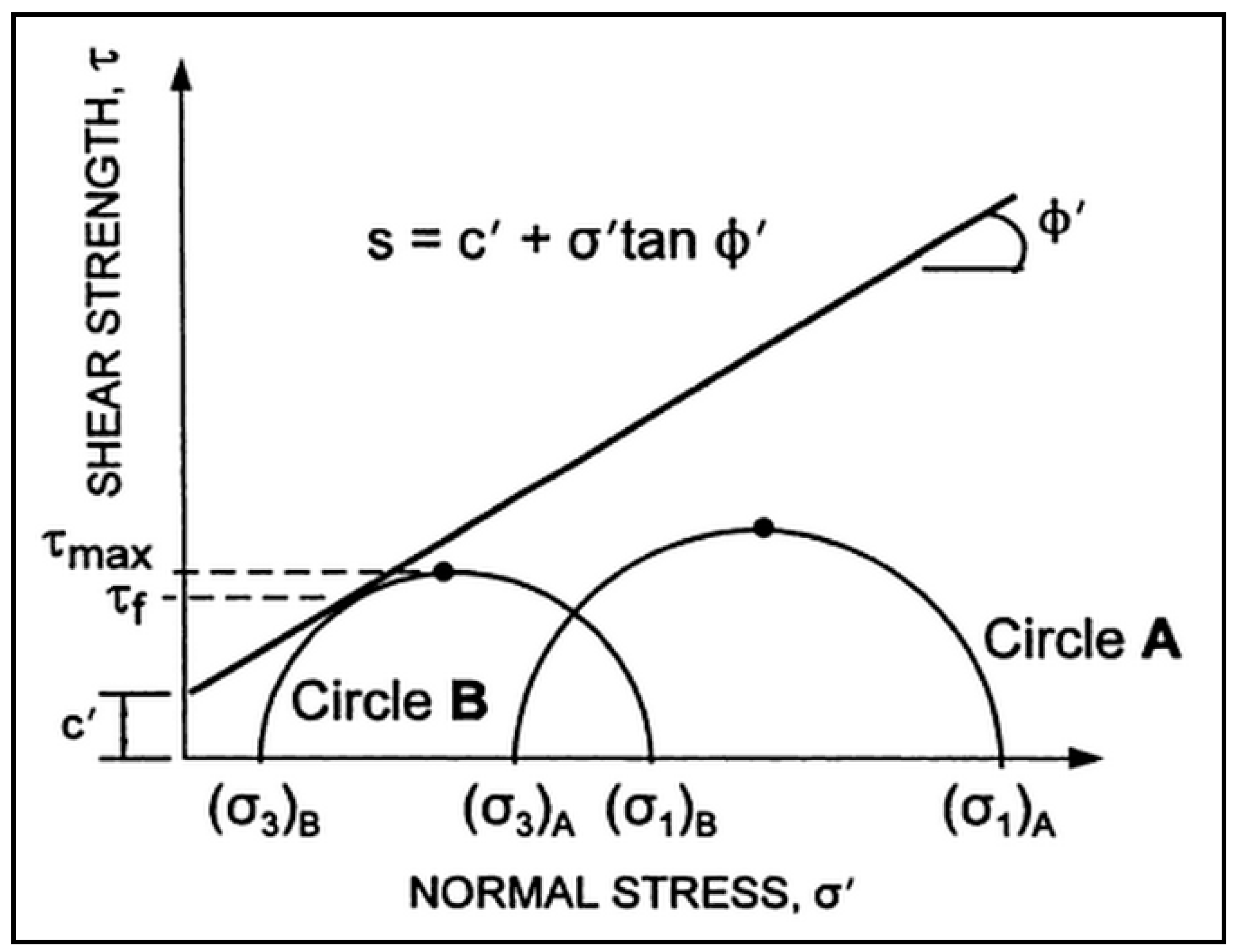
4. Design Methods
- c′ = effective cohesion of the soil, N/m2.
- σn = normal stress, N/m2.
- μw = pore water pressure, N/m2.
- ϕ′ = effective internal friction angle of the soil, degrees.
4.1. Bishop Method
- c′ = effective cohesion of the soil, N/m2.
- b = width of the slice, m.
- W = weight of the slice, N.
- P = total normal force on the base of the slice, N.
- β = slope angle, degrees.
- μw = pore water pressure, N/m2.
- α = inclination angle of the base of the slice, degrees.
- ϕ′ = effective internal friction angle of the soil, degrees.
- mα = cosα + [(sinα × tanϕ′)/FS].
- MP = moment about the center of the circle produced by P, N·m.
- R = radius of the circle, m.
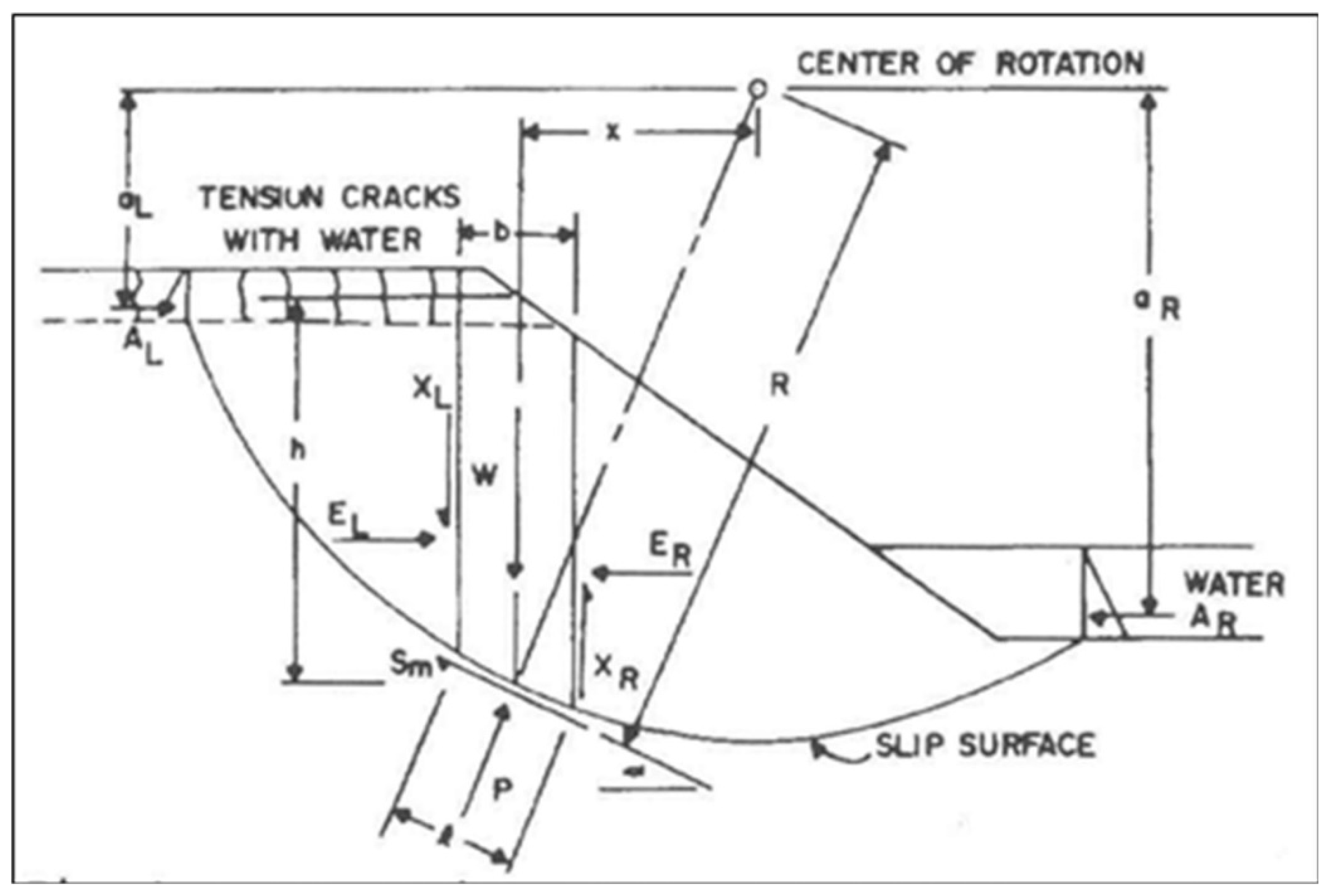
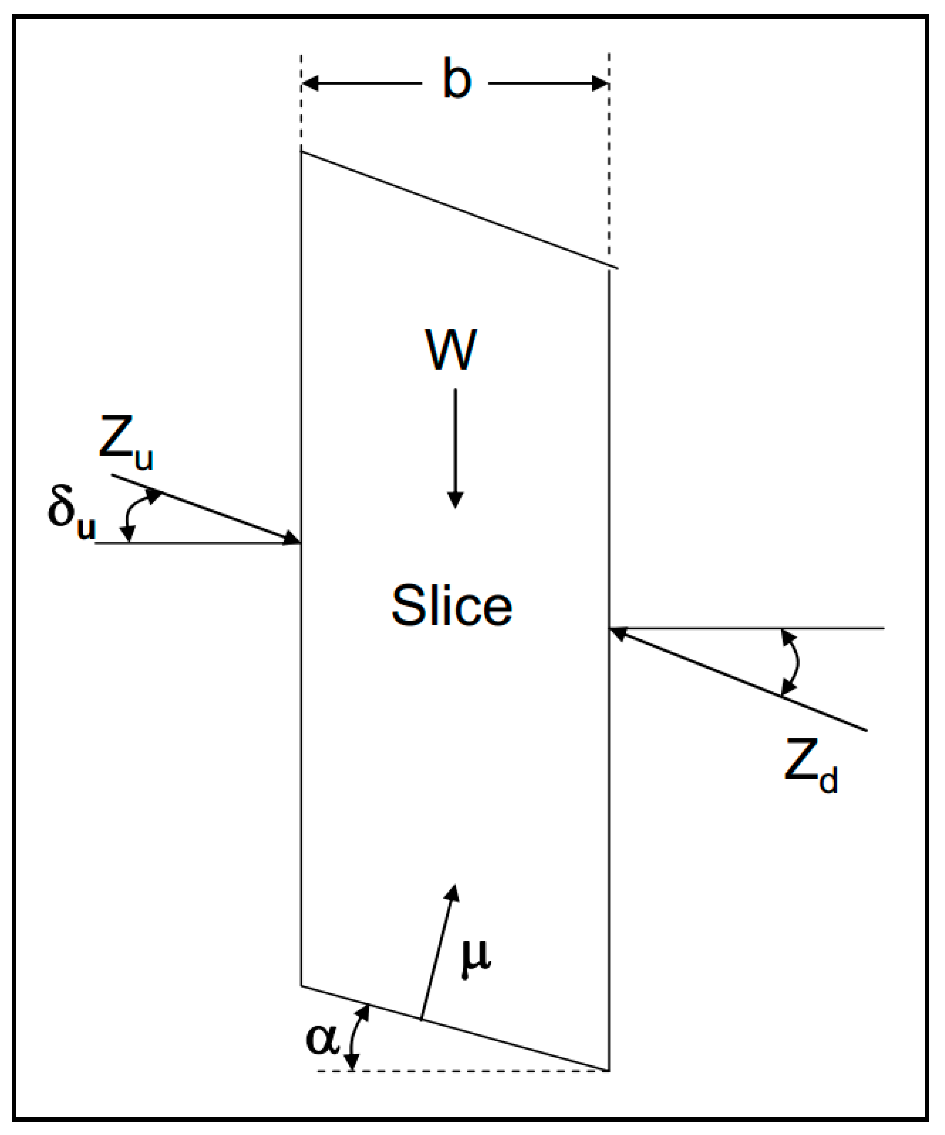
4.2. Spencer Method
- Zu = interslice force on the upslope side, N.
- Zd = interslice force on the downslope side, N.
- Mn = net system moment, N·m.
- c = cohesion of the soil, N/m2.
- FS = factor of safety.
- b = width of the slice, m.
- α = inclination angle of the base of the slice, degrees.
- γ = unit weight of the soil, N/m3.
- ϕ = internal friction angle of the soil, degrees.
- μ = pore pressure, N/m2.
- δ = angle of interslice force, degrees.
- u,d = upslope or downslope side of the slice.
- i,j = slice number.
- δi = angle of interslice force on the upslope side, degrees.
- ki = 1 (linearly reduced to 0 over the last 20 percent of slices).
- θ = constant angle (Spencer’s theta), degrees.
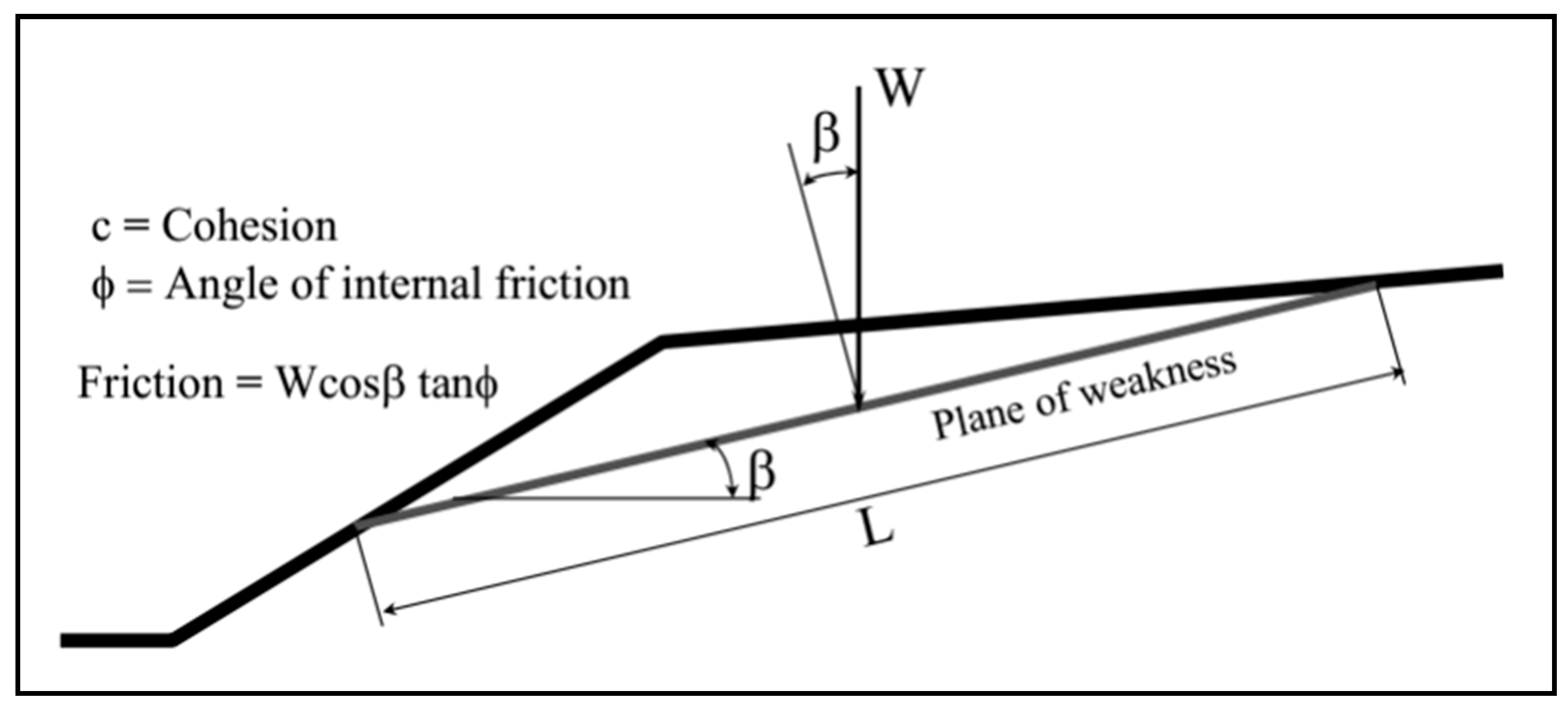
4.3. Jewell Method
- T = tensile force, N/m.
- K = equivalent earth pressure coefficient.
- γ = unit weight of the soil, N/m3.
- H = height of the slope, m.
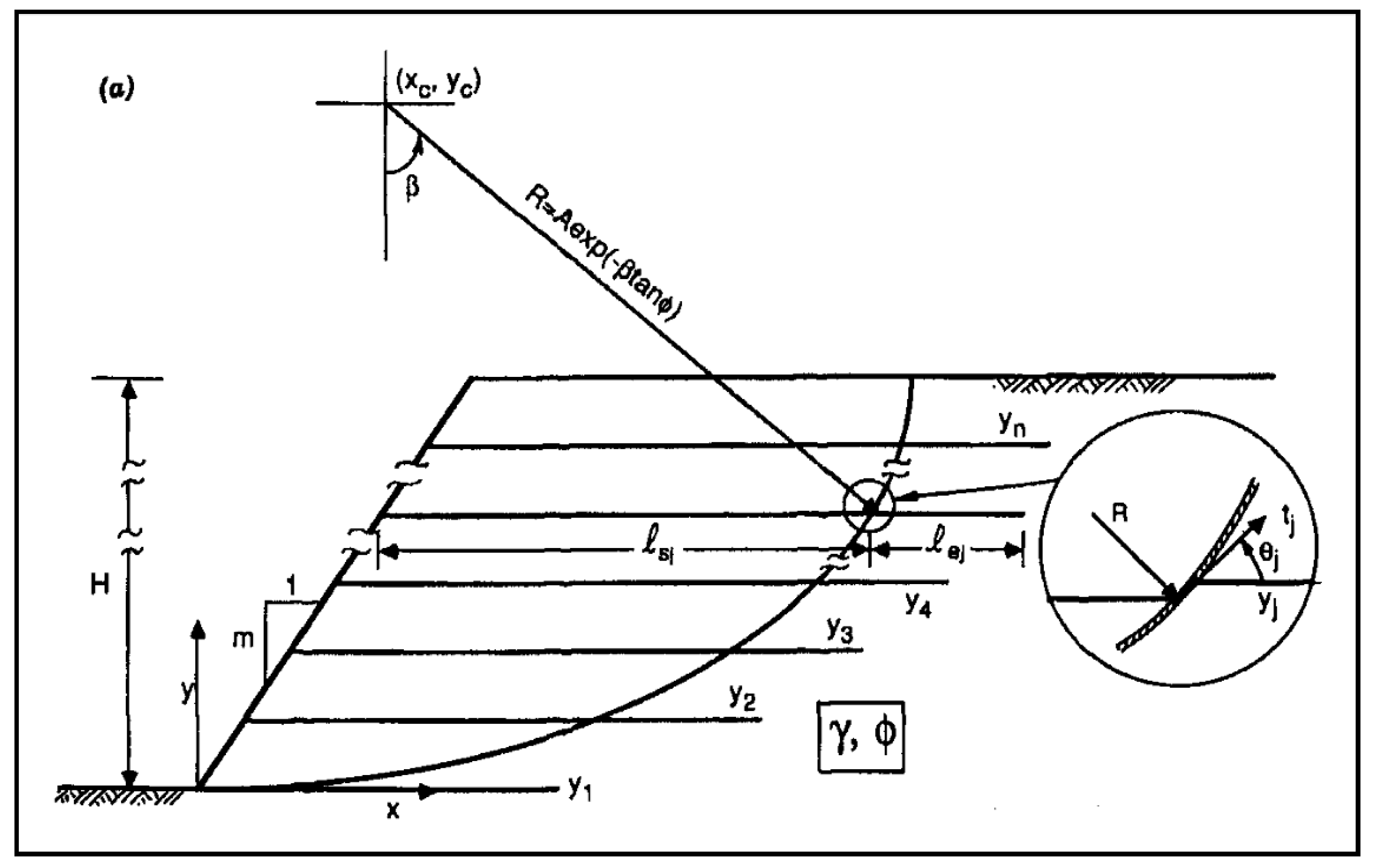
4.4. Leshchinsky Method
- tj = pullout resistance per unit width of geosynthetic sheet (j), N/m.
- k = coefficient of friction at the soil-geosynthetic interface.
- ϕ = internal friction angle of the soil, degrees.
- σ = average normal stress, N/m2.
- Lej = embedment length of geosynthetic sheet (j) beyond the slip surface, m.
4.5. Federal Highway Administration Method
5. Construction Practices
5.1. Construction Sequence
5.2. Transportation Agency Specifications
6. Performance Measures & Cost Effectiveness
6.1. Quality Control
6.2. Failure Modes
- All but one were privately owned (as opposed to publicly financed).
- 72 percent were in North America.
- 49 percent were 4 m to 8 m high.
- 90 percent were geogrid reinforced.
- 81 percent failed in less than 4 years.
- 62 percent used silt or clay backfill in the reinforced soil zone.
- 75 percent had poor to moderate compaction.
- 98 percent were caused by improper design or construction.
- 58 percent were caused by internal or external water (the remaining 42 percent were caused by soil related issues).
7. Conclusions & Recommendations
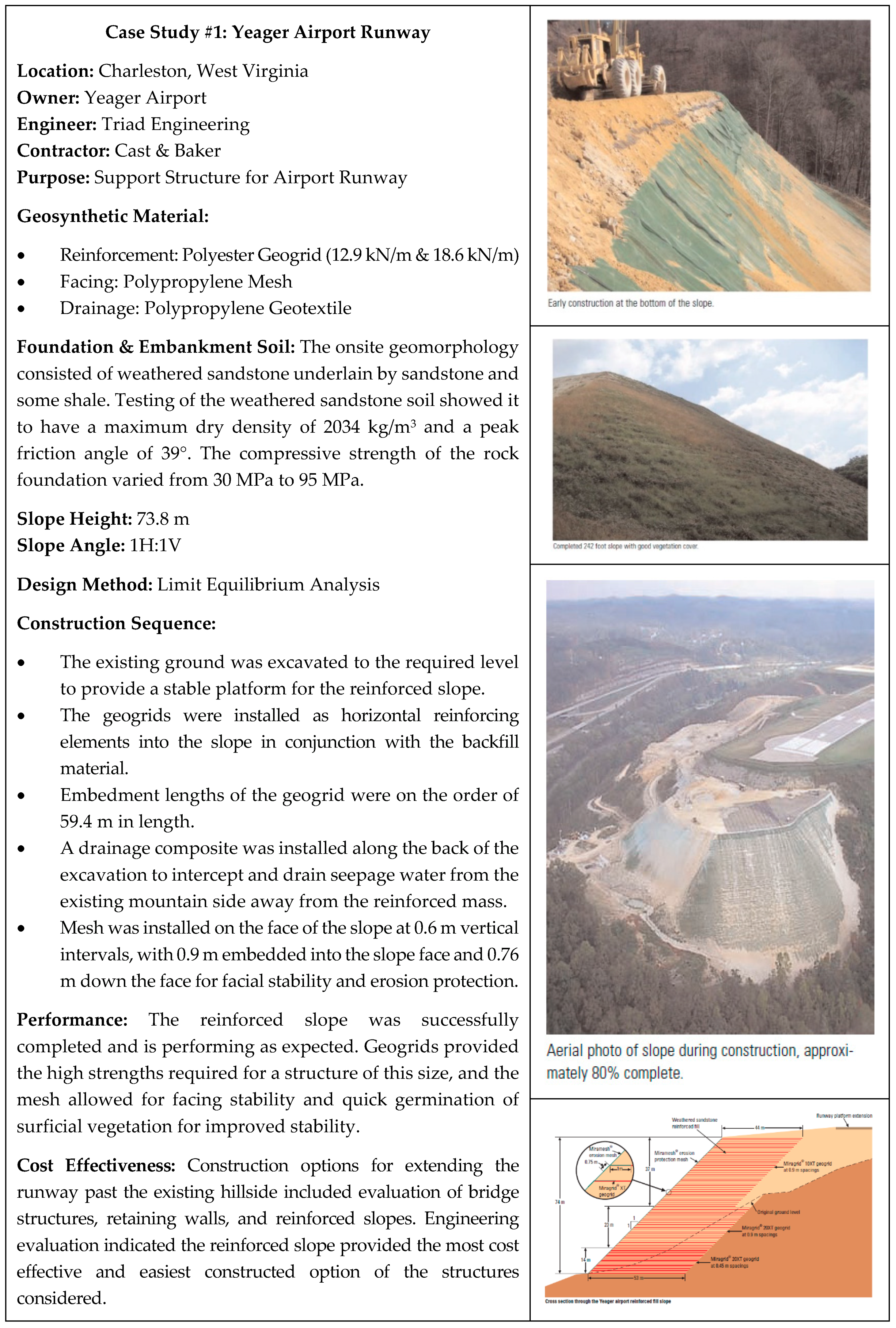
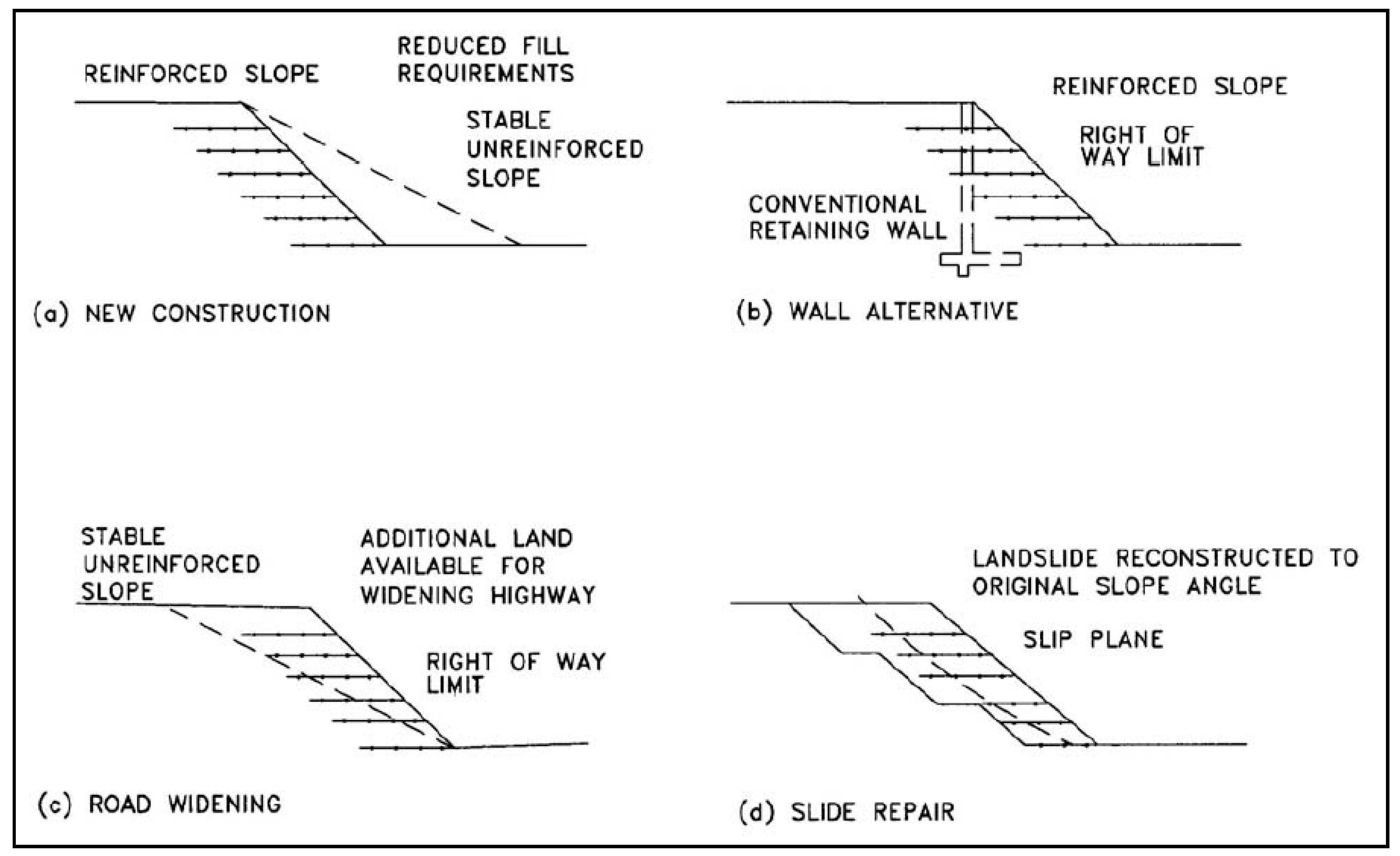
- Reinforced slopes are a form of mechanically stabilized earth that incorporate planar reinforcing elements for the construction of sloped structures with inclinations less than 70°. To provide tensile resistance and stability, geosynthetic reinforcement has been employed for repairing failed slopes, constructing new embankments, and widening existing embankments.
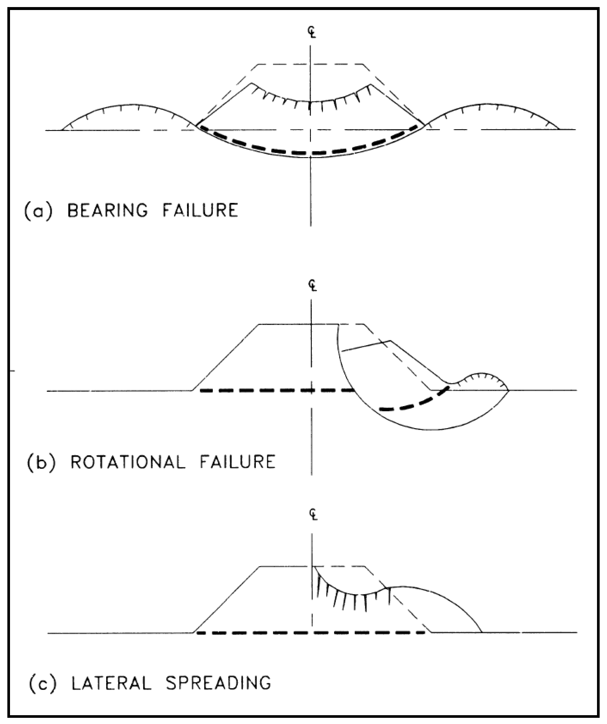
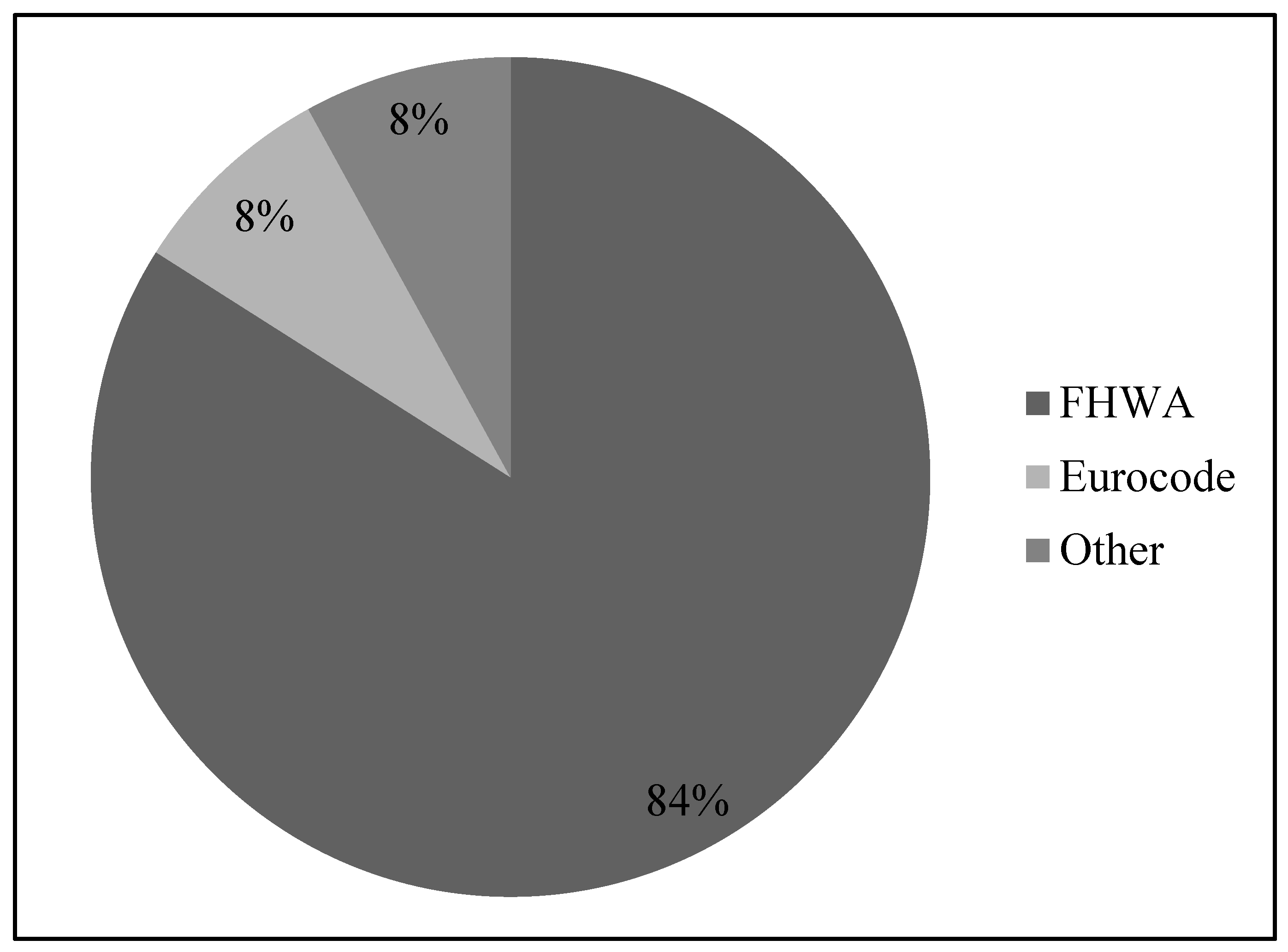
- According to the survey, following the FHWA design guidelines is the most advocated approach for designing reinforced slopes. Other common design methods have been developed by Jewell, Leshchinsky, and Eurocode. Internal and external stability are considered, including rotational, sliding, bearing, and lateral failure.
- Geogrids and geotextiles manufactured from polyester, polypropylene, or polyethylene are commonly used for reinforcement. The material must be resistant to all naturally occurring alkaline and acidic soil conditions, resistant to heat, ultraviolet light, and to attack by bacteria and fungi in the soil.
- An adequate subsurface investigation should be performed for the existing foundation, as well as behind and in front of the structure, to assess overall performance behavior. To facilitate compaction, a high quality fill meeting gradation, shear strength, and internal friction angle requirements are recommended for the embankment soil.
- The reinforcement is placed with the principal strength direction perpendicular to the face of the slope, pulled taut, and secured with retaining pins to prevent movement during fill placement. Backfill material is placed and compacted without deforming the reinforcement, utilizing lightweight compaction equipment near the slope face to maintain alignment.
- Performance monitoring programs are recommended for cases in which new features or materials have been incorporated in the design, post construction settlements are anticipated, or where degradation/corrosion rates of reinforcements are to be monitored.
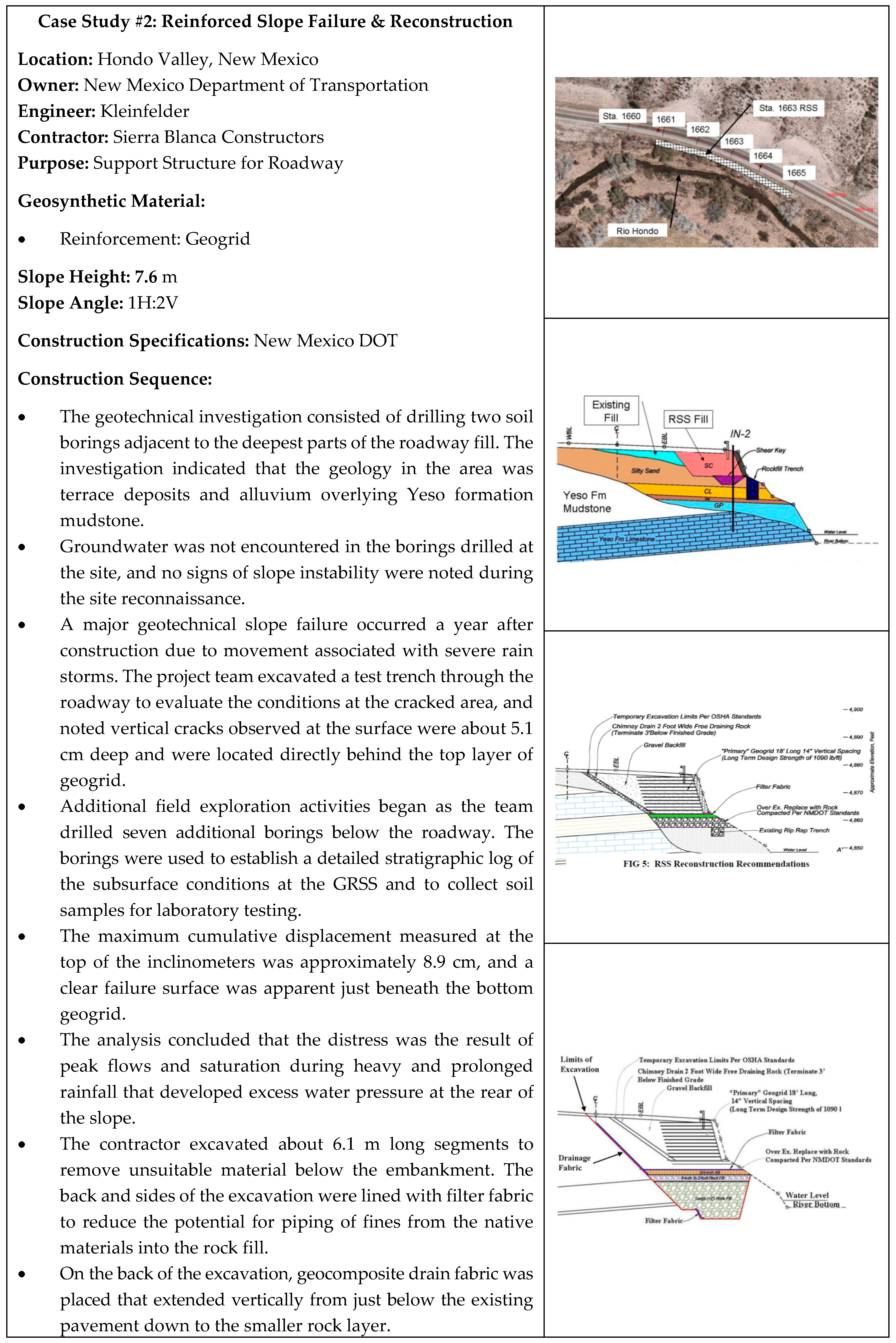
- Geosynthetics can be degraded by a combination of environmental mechanisms. However, none of the documented failures were due to inadequate reinforcement. All failures within the reviewed body of literature were due to improper design in the area of surface and internal water removal or the use of fine grained silt and clay backfill soils.
- Many site specific characteristics contribute to the overall cost, including cut-fill requirements, slope size and type, existing soil type, available backfill materials, facing finish, and application. The approximate costs of the principal components are as follows: reinforcement 45–65 percent, backfill 30–45 percent, and face treatment 5–10 percent.
- There is a need to use the specification and construction checklists, as well as implementing a comprehensive performance monitoring program, in order to compare the observed behavior and the intended design.
- The FHWA design guidelines should be followed. In addition, there is a need to follow the existing topography, soil properties, and subsurface conditions in evaluating the construction site. The investigation should also seek to determine the backfill materials as well as availability of the required type of reinforced fill.
- It is also recommended that the polyester, polypropylene, or polyethylene’s constructed geotextile or geogrid should be used in reinforcing deep slopes. The materials should have characteristics such as heat resistance, ultraviolet resistance, and fungi and bacteria attack resistance, as well as resistance to alkaline and acidic soil conditions.
- There is also a need to use free draining backfill having the recommended gradation limits of AASHTO T-27 in the reinforced volume. Moreover, there should be a plasticity index of less than 20 and a pH level of 5–10 in addition to the reinforced fill being reasonably free from organic or other such deleterious materials. When developing design calculations, factors such as soils density, cohesion, and internal friction angle must be determined and taken into consideration.
- It is also recommended that the surface water runoff must be collected above the slope that has been reinforced prior to channeling the water to slope’s base. The subsurface water drainage features must also be designed in order to address the challenges of filtration, flow rate, placement, and outlet details.
- Facing elements should also be designed appropriately such that if the slope facing is designed to prevent soil erosion, the face’s reinforcement should turn up and return into the next reinforcement layer’s embankment below it. The other most commonly used facing elements include different meshes made up of steel or polymers, which make it possible for the face to be vegetated after it has been constructed.
Author Contributions
Funding
Acknowledgments
Conflicts of Interest
Appendix A
Appendix B
- Geometric and Load Requirements:
- Slope Height (H) = 6.1 m
- Slope Angle (β) = 70°
- Surcharge Load (q) = 12 kN/m2
- Crest Width (A) = 6.1 m
- Performance Requirements:
- Internal Stability: FS = 1.5
- External Stability: FS = 1.5
- Foundation and Retained Soils:
- Internal Friction Angle (ϕu′) = 34°
- Cohesion (cu′) = 0
- Density (γu) = 19.6 kN/m3
- Reinforced Soil:
- Internal Friction Angle (ϕr′) = 34°
- Cohesion (cr′) = 0
- Density (γr) = 19.6 kN/m3
- Depth of Water Table (dw) = 5 ft
- ϕf = [tan−1 × (tanϕr/FS)] = [tan−1 × (tan34°/1.5)] = 24.2°
- K = 0.34 as per reference 10
- TS-MAX = [0.5 × K × γr × (H′)2] = {0.5 × 0.34 × 19.6 × [6.1 + (12/19.6)]2} = 150.1 kN/m
- TMAX = [(TS-MAX × Sv)/H)] × (RFID × RFCR × RFD)
- = [(150.1 × 0.4)/6.1)] × (1.2 × 3.0 × 1.25)
- = 44.3 kN/m
- L/H′ = 0.8 as per reference 10
- L = (L/H′) × H′ = 0.8 × [6.1 + (12/19.6)] = 5.37 m
| H = 6.1 m | (height) |
| β = 70° | (slope angle) |
| q = 10.1 kN/m2 | (surcharge load) |
| c = 0 | (soil cohesion) |
| ϕ = 32° | (soil internal friction angle) |
| γ = 20 kN/m3 | (soil unit weight) |
| FSdesign = 1.30 | (design factor of safety) |
| FSgrid = 2.75 | (geogrid factor of safety) |
| Tult = 65.7 kN/m | (geogrid tensile strength) |
| ru = 0.25 | (pore water pressure coefficient) |
- (1)
- Calculate the allowable tensile strength (Tallow) and design tensile strength (P).
- Tallow = (Tult/FSgrid) = (65.7/2.75) = 23.9 kN/m
- P = (Tallow/FSdesign) = (23.9/1.30) = 18.4 kN/m
- (2)
- Based on the pore water pressure coefficient, determine the coefficient of earth pressure (K) and the ratios of reinforcement length to embankment height (L/H)overall and (L/H)sliding using the charts in reference 10, then calculate the reinforcement length.
- K = 0.30
- (L/H)overall = 0.65
- (L/H)sliding = 0.60
- H′ = [H + (q/γ)] = [6.1 + (10.1/20)] = 6.6 m
- L = [H′ × (L/H)overall] = (6.6 × 0.65) = 4.3 m
- (3)
- Define the spacing constant (Q) for the slope in terms of the minimum spacing (v) to be used.
- v = 0.2 m
- Q = [P/(K × γ × v)] = [18.4/(0.30 × 20 × 0.2)] = 15.33 m,
- (4)
- Define the zones for reinforcement layers spaced equally at v1, v2, v3, … vn.
i Spacing (Svi) Depth (Zi) Thickness (si) 1 1v = 0.2 m Q = 15.33 m - 2 2v = 0.4 m Q/2 = 7.67 m 7.67 − 5.11 = 2.56 m 3 3v = 0.6 m Q/3 = 5.11 m 5.11 − 3.83 = 1.28 m 4 4v = 0.8 m Q/4 = 3.83 m - (5)
- Calculate the number and position of the required reinforcement layers. The number of grids in a zone (N) is rounded down to the nearest whole number.
i si′/Svi Number of Grids (Ni) Remaining Thickness (Ri = si−1 − (Svi × Ni)) si+1′ = si+1 + Ri 0 1 R0 = base 1 2.56 m/0.4 m = 6.4 6 R1 = 2.56 − (0.4 × 6) = 0.16 m s2′ = 1.28 + 0.16 = 1.44 m 2 1.44 m/0.6 m = 2.4 2 R2 = 1.44 − (0.6 × 2) = 0.24 m s3′ = 3.83 + 0.24 = 4.07 m 3 4.07 m/0.8 m = 5.09 5 R3 = 4.07 − (0.8 × 5) = 0.07 m
- (6)
- Calculate the gross horizontal force for equilibrium and check the geogrid tensile force.
- T = [0.5 × K × γ × (H′)2] = [0.5 × 0.30 × 20 × (6.6)2] = 130.7 kN/m
- T/Ntotal = 130.7/15 = 8.71 kN/m
- T/Ntotal ≤ P
References
- Holtz, R.D.; Christopher, B.R.; Berg, R.R. Geosynthetic Design and Construction Guidelines; Federal Highway Administration: Washington, DC, USA, 1998.
- Rimoldi, P.; Ricciuti, A.; Recalcati, P. Steep Reinforced Slopes; TENAX: Baltimore, MD, USA, 2006. [Google Scholar]
- S&P. Geosynthetic Reinforced Steep Slopes; S&P Clever Reinforcement Company: Seewernstrasse, Sweden, 2009. [Google Scholar]
- Elias, V.; Christopher, B.R.; Berg, R.R. Mechanically Stabilized Earth Walls and Reinforced Soil Slopes Design and Construction Guidelines; Federal Highway Administration: Washington, DC, USA, 2001.
- Vidal, H. The principle of reinforced earth. Transp. Res. Rec. 1969, 282, 1–16. [Google Scholar]
- Jones, W.V.; Anderson, L.R.; Bishop, J.A.; Holtz, R.D.; Wu, T.H. Reinforcement of Constructed Earth. Committee on Placement and Improvement of Soils; American Society of Civil Engineers: Atlantic City, NJ, USA, 1987. [Google Scholar]
- Holtz, R.D. The Civil Engineering Handbook, 2nd ed.; CRC Press: Danvers, MA, USA, 2003. [Google Scholar]
- Leshchinsky, D.; Ling, H.; Hanks, G. Unified design approach to geosynthetic reinforced slopes and segmental walls. Geosynth. Int. 1995, 2, 845–881. [Google Scholar] [CrossRef]
- Rowe, R.K.; Jones, C.J. Geosynthetics: Innovative materials and rational design. In Proceedings of the GeoEng2000: An International Conference on Geotechnical and Geological Engineering, Melbourne, Australia, 19–24 November 2000. [Google Scholar]
- Berg, R.R.; Christopher, B.R.; Samtani, N.C. Design of Mechanically Stabilized Earth Walls and Reinforced Soil Slopes; Federal Highway Administration: Washington, DC, USA, 2009.
- McGown, A.; Kupec, J.; Heerten, G.; Von Maubeuge, K. Testing biaxial geogrids for specification and design purposes. In Geosynthetics Research and Development in Progress; American Society of Civil Engineers: Atlantic City, NJ, USA, 2005. [Google Scholar]
- Pathak, Y.P.; Alfaro, M.C. Laboratory simulation of seasonal wetting-drying cycles on geosynthetic-reinforced clay slopes and embankments. In Geosynthetics Research and Development in Progress; American Society of Civil Engineers: Atlantic City, NJ, USA, 2005. [Google Scholar]
- Hsieh, C.W. Ongoing Geosynthetics Researches of GSI-Taiwan: Geosynthetics Research and Development in Progress; American Society of Civil Engineers: Reston, VA, USA, 2005. [Google Scholar]
- Berg, R.R.; Suits, L.D. Geosynthetics; Transportation Research Board: Washington, DC, USA, 1999. [Google Scholar]
- Kim, M.; Oh, T.; Han, S.; Joo, S.; Jeon, H.; Chang, D. Preparation of Poly (vinyl alcohol)/Silver-Zeolite Composite Hydrogels by UV-Irradiation. Fiber Polym. 2014, 15, 101–107. [Google Scholar] [CrossRef]
- GEOfabrics Limited. An Introduction to Geosynthetics; International Geosynthetics Society: Stourton, UK, 2011. [Google Scholar]
- ASTM D5262. Standard Test Method for Evaluating the Unconfined Tension Creep and Creep Rupture Behavior of Geosynthetics; ASTM International: West Conshohocken, PA, USA, 2012. [Google Scholar]
- Muller-Rochholz, J.; Reinhard, K. Creep of geotextiles at different temperatures. In Proceedings of the International Conference on Geotextiles, Geomembranes & Related Products, Hague, The Netherlands, 28 May–1 June 1990; pp. 657–659. [Google Scholar]
- Becker, L.D. Creep of Geotextiles Confined in Experimental Fill; Federal University of Rio Grande do Sul: Porto Alegre, Brazil, 2001. [Google Scholar]
- Alabama DOT. Standard Specifications for Highway Construction; Alabama Department of Transportation: Montgomery, AL, USA, 2012. [Google Scholar]
- California DOT. Geosynthetic Reinforced Embankment; California Department of Transportation: Sacramento, CA, USA, 2005.
- West Virginia DOT. Standard Specifications for Roads and Bridge; West Virginia Department of Transportation: Charleston, WV, USA, 2010.
- ASTM D4355. Standard Test Method for Deterioration of Geotextiles by Exposure to Light, Moisture and Heat in a Xenon Arc Type Apparatus; ASTM International: West Conshohocken, PA, USA, 2007. [Google Scholar]
- AASHTO T-27. Standard Test Method for Sieve Analysis of Fine and Coarse Aggregates; American Association of State Highway and Transportation Officials: Washington, DC, USA, 2011. [Google Scholar]
- AASHTO T-90. Standard Method of Test for Determining the Plastic Limit and Plasticity Index of Soils; American Association of State Highway and Transportation Officials: Washington, DC, USA, 2008. [Google Scholar]
- AASHTO T-104. Standard Method of Test for Soundness of Aggregate by Use of Sodium Sulfate or Magnesium Sulfate; American Association of State Highway and Transportation Officials: Washington, DC, USA, 2011. [Google Scholar]
- Florida DOT. Standard Specifications for Road and Bridge Construction; Florida Department of Transportation: Tallahassee, FL, USA, 2010.
- Pennsylvania DOT. Standard Special Provision for Geosynthetic Reinforced Slope Construction; Pennsylvania Department of Transportation: Harrisburg, PA, USA, 2007.
- Haliburton, T.A.; Anglin, C.C.; Lawmaster, J.D. Testing of geotechnical fabric for use as reinforcement. Geotech. Test. J. 1978, 1, 203–212. [Google Scholar]
- Chai, J.C.; Zhu, H.H. Behavior of Reinforced Embankment over Soft Subsoil; Practices and Advances in Geotechnical Engineering: Shanghai, China, 2009. [Google Scholar]
- Bonaparte, R.; Christopher, B.R. Design and Construction of Reinforced Embankments over Weak Foundations; Federal Highway Administration: Washington, DC, USA, 1987.
- Yoo, H.; Kim, H.; Jeon, H. Evaluation of Pullout and Drainage Properties of Geosynthetic Reinforcements in Weathered Granite Backfill Soils. Fibers Poly. 2007, 8, 635–641. [Google Scholar] [CrossRef]
- Ehrlich, M.; Becker, L. Reinforced Soil Walls and Slopes; Huesker: Sao Paulo, Brazil, 2010. [Google Scholar]
- Abramson, L.W. Slope Stability and Stabilization Methods; John Wiley & Sons: New York, NY, USA, 2002. [Google Scholar]
- Wilson, G.W.; Clifton, A.W.; Barbour, S.L. The Emergence of Unsaturated Soil Mechanics; NRC Research Press: Ottawa, ON, Canada, 1999. [Google Scholar]
- Whitman, R.V. Use of computers for slope stability analysis. J. Soil Mech. Found. Div. 1967, 93, 475–498. [Google Scholar]
- Bishop, A.W. The use of the slip circle in the stability of slopes. Geotechnique 1955, 5, 7–17. [Google Scholar] [CrossRef]
- Spencer, E. A method of analysis of the stability of embankments assuming parallel inter-slice forces. Geotechnique 1967, 17, 11–26. [Google Scholar] [CrossRef]
- USACE. Engineering and Design Slope Stability; United States Army Corps of Engineers: Washington, DC, USA, 2003. [Google Scholar]
- Jewell, R.A. Some Effects of Reinforcement on the Mechanical Behavior of Soils; University of Cambridge: Cambridge, UK, 1980. [Google Scholar]
- Jewell, R.A. Application of the Revised Design Charts for Steep Reinforced Slopes; AKZO Industrial Systems: Arnhem, The Netherlands, 1990. [Google Scholar]
- Leshchinsky, D.; Boedeker, R.H. Geosynthetic reinforced soil structures. J. Geotech. Eng.-ASCE 1989, 115, 1459–1478. [Google Scholar] [CrossRef]
- Yu, H.S.; Salgado, R.; Sloan, S.W.; Kim, J.M. Limit analysis versus limit equilibrium for slope stability. J. Geotech. Geoenviron. 1998, 124, 1–11. [Google Scholar] [CrossRef]
- Abramento, M.; Whittle, A.J. Shear-lag analysis of a planar soil reinforcement in plane strain compression. J. Eng. Mech. 1993, 119, 270–291. [Google Scholar] [CrossRef]
- Ehrlich, M.; Mitchell, J.K. Working stress design method for reinforced soil walls. J. Geotech. Eng.-ASCE. 1994, 120, 625–645. [Google Scholar] [CrossRef]
- Dantas, B.; Ehrlich, M. Analysis method for reinforced slopes under working stress. Int. J. Geotech. Geoenviron. 2000, 23, 113–133. [Google Scholar]
- Teixeira, S.H. Study of Soil-Geogrid Interaction in Pullout Tests and Its Use on Design and Analysis of Reinforced Soil Structures; University of Sao Paulo: Sao Paulo, Brazil, 2003. [Google Scholar]
- USACE. Unified Facilities Guide Specification; United States Army Corps of Engineers: Washington, DC, USA, 2008. [Google Scholar]
- TenCate. Geosynthetic Reinforced Steepened Slopes; TenCate Geosynthetics North America: Pendergrass, GA, USA, 2010. [Google Scholar]
- AASHTO T-99. Standard Method of Test for Moisture-Density Relations of Soils Using a 2.5 kg Rammer and a 305 mm Drop; American Association of State Highway and Transportation Officials: Washington, DC, USA, 2010. [Google Scholar]
- ASTM D4595. Standard Test Method for Tensile Properties of Geotextiles by the Wide-Width Strip Method; ASTM International: West Conshohocken, PA, USA, 2011. [Google Scholar]
- ASTM D6637. Standard Test Method for Determining Tensile Properties of Geogrids by the Single or Multi-Rib Tensile Method; ASTM International: West Conshohocken, PA, USA, 2011. [Google Scholar]
- Mississippi DOT. Standard Specifications for Road and Bridge Construction; Mississippi Department of Transportation: Jackson, MS, USA, 2004.
- Koerner, R.M.; Koerner, G.R. A data base and analysis of 141 failed geosynthetic reinforced mechanically stabilized earth (MSE) walls. In Proceedings of the 26th Central Pennsylvania Geotechnical Conference, Hershey, PA, USA, 24–26 October 2012. [Google Scholar]
- Liu, C.N.; Yang, K.H.; Ho, Y.H.; Chang, C.M. Lessons learned from three failures on a high steep geogrid-reinforced slope. Geotext. Geomembr. 2012, 34, 131–143. [Google Scholar] [CrossRef]

| Soil Environment | PET | PE | PP |
|---|---|---|---|
| Acid Sulphate Soils | NE | ETR | ETR |
| Organic Soils | NE | NE | NE |
| Saline Soils (pH < 9) | NE | NE | NE |
| Ferruiginous Soils | NE | ETR | ETR |
| Calcereous Soils | ETR | NE | NE |
| Modified Soils (Lime, Cement, etc.) | ETR | NE | NE |
| Sodic Soils (pH > 9) | ETR | NE | NE |
| Soils with Transition Metals | NE | ETR | ETR |
| PP = Polypropylene, PET = Polyester, PE = Polyethylene NE = No Effect, ETR = Exposure Tests Required | |||
| Geosynthetic Type | Weight 2 (g/m3) | Ultimate 3 Tensile Strength (kN/m) | Strain at 3 Ultimate Tensile Strength (%) | Secant 3 Modulus at 10% Strain (kN/m) | Grab 4 Strength (N) | Puncture 5 Strength (N) | Burst 6 Strength (kPa) | Tear 7 Strength (N) | Equivalent 8 Darcy Permeability (m/s) |
|---|---|---|---|---|---|---|---|---|---|
| Monofilament Polypropylene Geotextile | 120–240 | 16–70 | 20–40 | 70–260 | 700–2300 | 320–700 | 2700–4800 | 200–440 | 10−4–10−2 |
| Silt Film Geotextile | 50–170 | 12–45 | 20–40 | 50–260 | 32–1600 | 80–600 | 1400–4800 | 200–1600 | 10−4–10−3 |
| Fibrillated Tape and Multifilament Polypropylene Geotextile | 240–760 | 35–210 | 15–40 | 175–700 | 700–6200 | 700–1100 | 4100–10400 | 440–1800 | 10−4–10−3 |
| Multifilament Polyester Geotextile | 140–710 | 25–350 | 10–30 | 175–10500 | 700–9000 | 200–1400 | 3400–10400 | 360–2300 | 10−4–10−3 |
| Polypropylene Geogrid | 140–240 | 8–35 | 10–20 | 90–230 | n/a | n/a | n/a | n/a | >10 |
| High Density Polyethylene Geogrid | 240–710 | 8–90 | 10–20 | 55–70 | n/a | n/a | n/a | n/a | >10 |
| Polyester Geogrid | 240–710 | 35–140 | 5–15 | 350–2600 | n/a | n/a | n/a | n/a | >10 |
| Gradation (AASHTO T-27) | Sieve Size | Percent Passing (%) |
| 4 in. | 100 | |
| #4 | 100–20 | |
| #40 | 60–0 | |
| #200 | 50–0 | |
| Plasticity Index (AASHTO T-90) | PI (Plastic Index) ≤ 20 | |
| Soundness (AASHTO T-104) | Magnesium sulfate soundness loss less than 30% after 4 cycles, based on AASHTO T-104 or equivalent sodium sulfate soundness of less that 15% after 5 cycles. | |
© 2019 by the authors. Licensee MDPI, Basel, Switzerland. This article is an open access article distributed under the terms and conditions of the Creative Commons Attribution (CC BY) license (http://creativecommons.org/licenses/by/4.0/).
Share and Cite
Kim, Y.-J.; Kotwal, A.R.; Cho, B.-Y.; Wilde, J.; You, B.H. Geosynthetic Reinforced Steep Slopes: Current Technology in the United States. Appl. Sci. 2019, 9, 2008. https://doi.org/10.3390/app9102008
Kim Y-J, Kotwal AR, Cho B-Y, Wilde J, You BH. Geosynthetic Reinforced Steep Slopes: Current Technology in the United States. Applied Sciences. 2019; 9(10):2008. https://doi.org/10.3390/app9102008
Chicago/Turabian StyleKim, Yoo-Jae, Ashley Russell Kotwal, Bum-Yean Cho, James Wilde, and Byung Hee You. 2019. "Geosynthetic Reinforced Steep Slopes: Current Technology in the United States" Applied Sciences 9, no. 10: 2008. https://doi.org/10.3390/app9102008
APA StyleKim, Y.-J., Kotwal, A. R., Cho, B.-Y., Wilde, J., & You, B. H. (2019). Geosynthetic Reinforced Steep Slopes: Current Technology in the United States. Applied Sciences, 9(10), 2008. https://doi.org/10.3390/app9102008