1. Introduction
Power electronic converters have major roles in renewable energy resources, energy storage systems, electric or hybrid electric vehicles (HEVs), and aerospace application [
1,
2,
3,
4]. Isolated Gate Bipolar Transistors (IGBTs) and Metal-Oxide-semiconductor Field-Effect Transistors (MOSFETs) are two well-known power switches, which are the main active components in power converters. The IGBT stands out for high power density which makes it practical in high power applications such as wind energy generation systems, electric rail transportation systems, etc. [
5,
6,
7]. On the other hand, MOSFETs offer high frequency switching which improve the dynamics of the converters [
8,
9]. Nevertheless, the high switching frequency leads to high dv/dt and increases power loss and electromagnetic emissions [
10]. Despite their features, the two mentioned power switches suffer from a high failure rate. The high failure rate of switches decreases the reliability of converters. Regarding the essential role of converters in the critical applications, reliability of the converters, which are considered the main parts of the system, becomes an important challenge [
11,
12,
13]. Hence, the issue is gaining more attention and is considered as a major step in design and operation of systems [
14].
In [
15,
16], some fault tolerant cascaded multilevel inverters are suggested; the suggested structures use certain relays to isolate the failure parts. Similarly, in [
17] the relays are used to isolate the failed branches of the interleaved dc-dc converter. Since relays have an insignificant failure rate, these devices could improve the reliability. On the contrary, relays are pretty slow and the converter task will be interrupted for some milliseconds when the relays act to remove the failure parts. Another strategy to enhance the expected life span of power electronic devices is to use redundant configurations and reconfiguration strategies, as investigated in [
18]. The researchers in [
18] focus on the effect of the redundancy of a Power Distribution Unit (PDU)-reliant system and prove that any failure in the PDU, which uses no redundancy, can cause the whole system to fail. According to [
19], by adding a redundant switch to a silicon carbide (SIC)-based three-phase inverter, the MTTF of the inverter can be increased by approximately five times. Furthermore, [
19] suggests making a trade-off between the efficiency and reliability in the studied high-power inverter. In [
20], the reliability of the dc-dc converter utilized in a solar farm is studied, where the converters in solar farms deal with different power ranges, and thereby having different MTTF, are associated. In order to obtain an overall MTTF for such a system, [
20] suggests an average MTTF which is given by
(
n is the number of operation conditions). The failure rate and MTTF obtained in this reference are based on MIL-HDBK-217 F military handbook [
21]. In certain applications, the system interruption may lead to immense economic losses and/or life-threatening conditions. [
22] makes use of a special switching method to control the main and redundant power switches to the end of reducing the Electromagnetic Interface (EMI) which is produced by the converter, so that a safe condition is provided for the other components of the system. Thus, in turn, the overall high reliability of the system is achieved.
Reliability evaluation methods are needed to evaluate the reliability of the systems. These methods can provide a valuable guideline to manage the system performance in its mission profile. Some studies have evaluated the availability and reliability of power electronic based systems and their components through conventional reliability analyzing methods, such as fault tree and Markov models [
23]. The Markov model is based on a graphical representation of the operation states of the system. The operation states, which are related to system configuration, are obtained by assuming the possible sequence of elemental faults and the system reconfiguration steps. [
24] exemplifies the Markov chain method in the reliability field and the probability-based reliability theory is used to study the lifetime of large solar Photovoltaic (PV) arrays. Due to the fact that different power electronic devices have different failure rates, the MTTF of a converter must be calculated based on a static value. As reported in literature, the reliability of a component is associated with uncertainties that originate from manufacturing technology, design uncertainty and lack of sufficient knowledge of physics of failure [
25,
26,
27]. Regarding the mentioned fact and knowing that the failure rates of components and fault-coverage-mechanism probability are not pre-defined values, fuzzy-based reliability analysis can be a suitable technique in common systems architecture [
28,
29,
30,
31].
In light of the above, the fuzzy mathematics theory can be combined with a Markov model as an alternative method to calculate the MTTF of power-electronic-based converters. This paper focuses on the application of fuzzy logic in the reliability evaluation of a fault-tolerant multi-phase interleaved dc-dc converter (hereinafter is called converter for brevity). In this regard, fuzzy-based Markov chains are developed to analyze the MTTF of the considered converter. In order to enhance the reliability of the considered converter, redundant-phase and redundant-switch configurations are considered. Then by using fuzzy logic theory, the fuzzy functions of the MTTF for the single-phase, two-phase and three-phase modes, in the presence of the redundant-switch configurations, are extracted. The considered redundant-switch configurations are termed as parallel-switch and standby-switch configurations. Moreover, assuming different conditions, the junction temperature and the thermal factors of the switches are calculated. The obtained fuzzy results of the MTTFs are translated into certain indexes to provide a fair comparison between the reliability of the converters equipped with different redundant configurations. The whole work is converged to approach to a suitable defuzziation method to enhance the reliability of the interleaved dc-dc converter. To sum up, this paper is aimed at investigating the fuzzy reliability of interleaved converter with redundant switch configuration. To best of the authors’ knowledge, there is no research to investigate the reliability of fault-tolerant interleaved converters from the fuzzy concept point of view. This research presents a systematic process to evaluate the reliability of the interleaved dc-dc converters through fuzzy functions of switch base-failure and probability of successful operation of the fault managing system. The presented process consists of three analysis tools, i.e., failure rates calculation, Markov chains and fuzzy theory application in MTTF functions derivation. Contrary to expectation, the results show that under certain conditions, an n-phase converter is not more reliable than a (n-1)-phase converter. Moreover, for an n-phase converter, the suitability of each switch configuration should be assessed to determine the best configuration.
The MTTF analyses simulation result obtained in Matlab/Simulink and experimental results extracted from a lab-scale prototype are provided to analyze the performance of the converter equipped with the studied redundant-switch configurations.
2. The Studied Dc-Dc Converters
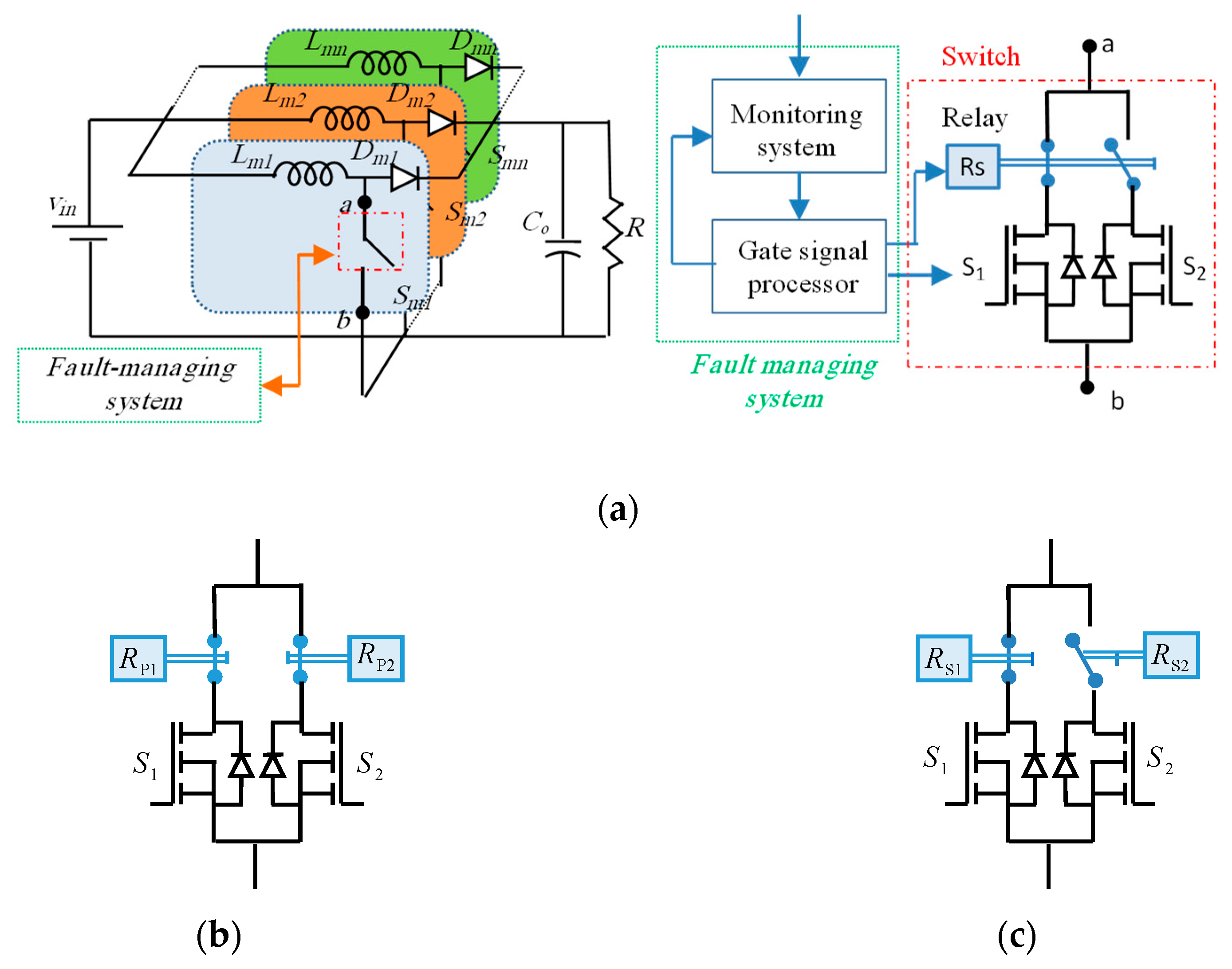
Figure 1a shows the general configuration of an
n-phase interleaved boost converter in which each phase operates with a phase-shift of
2π/n. This converter features high efficiency, compact size, easy thermal management and low input current ripple. The converter is also equipped with a fault managing system to detect the fault and isolate it by reconfiguring the converter through some relays. In order to enhance the reliability of the converter, a hybrid-redundant structure is employed. This structure is combined with redundant-phase and redundant-switch configurations. As shown in
Figure 1b,c, two common redundant structures for power switches, which are termed as parallel and standby switch configurations, can be considered to fend off the fault effect [
32]. In this strategy, the mentioned redundant-switch configurations are replaced with the single switch in each phase. In the parallel-switch configuration, which is shown in
Figure 1b, two relays with a normally-closed contactor are used. However, in the standby-switch configurations, only one relay is used. The relay in this configuration has one normally-closed and one normally-opened contactor.
Figure 1c shows the standby-switch configuration. The relays get excited individually by the fault managing system under faulty conditions. In parallel-switch configuration, when one of the switches (S
j) fails the fault managing system detects the faulty switch and opens the related contactor (R
pj). Therefore, the healthy switch conducts the total branch current. Once the second fault happens, the other contactor is opened to remove the faulty phase, thus the converter proceeds to function with the remaining phases. As shown in
Figure 1c in the standby-switch configuration, the switch S
2 is a reserve switch. Hence as the main switch (S
1) fails, the relay isolates it through contactor R
S1 and the reserve switch is replaced with the faulty switch by closing the contactor R
S2. When the reserve switch fails, the related phase is totally removed and the converter proceeds to operate with the healthy phases.
3. Markov Model
One important step to compare the reliability of power converter is to use a quantitative reliability evaluation which is executed by employing some suitable models. The Markov chain is one of the well-known reliability models which is used to evaluate the reliability of different power converters. In order to obtain the Markov model of a power converter, the failure rates of the utilized components must be calculated in different operation modes. Since power switch failure is more probable than that of the other devices [
32,
33], only the failure of the switches is considered in this paper. According to MIL-HDBK-217F, the failure rate of a semiconductor switch is given as:
where,
,
,
,
,and
are the basic failure rate, the quality of configuration factor, application factor, environment factor, and temperature factor, respectively. The basic failure rate can be obtained by referring to historical reports of power switch failure rates under normal and standard conditions. The other factors are accelerated factor that increase the failure rates of the power switch. For different manufacturing technology, environmental conditions, application type,
,
, and
, can be considered as fixed values. The temperature factor of semiconductor devices (
) can be calculated as follow:
where,
,
, and
are constant values [
33,
34], and
is the junction temperature of the power switch. In order to compare the MTTF of the switches, the power losses should be obtained. The total power loss of a typical switch is as follows:
where
,
,
, and
are average current of switch, voltage across the switch, switching frequency, and parasitic drain-source capacitor, respectively. Also,
,
,
, and
are the turn
on and
off switching times of the switch, Root Mean Squire (RMS) current passing through the switch and on-state resistance of the switch, respectively. Having the failure rates (
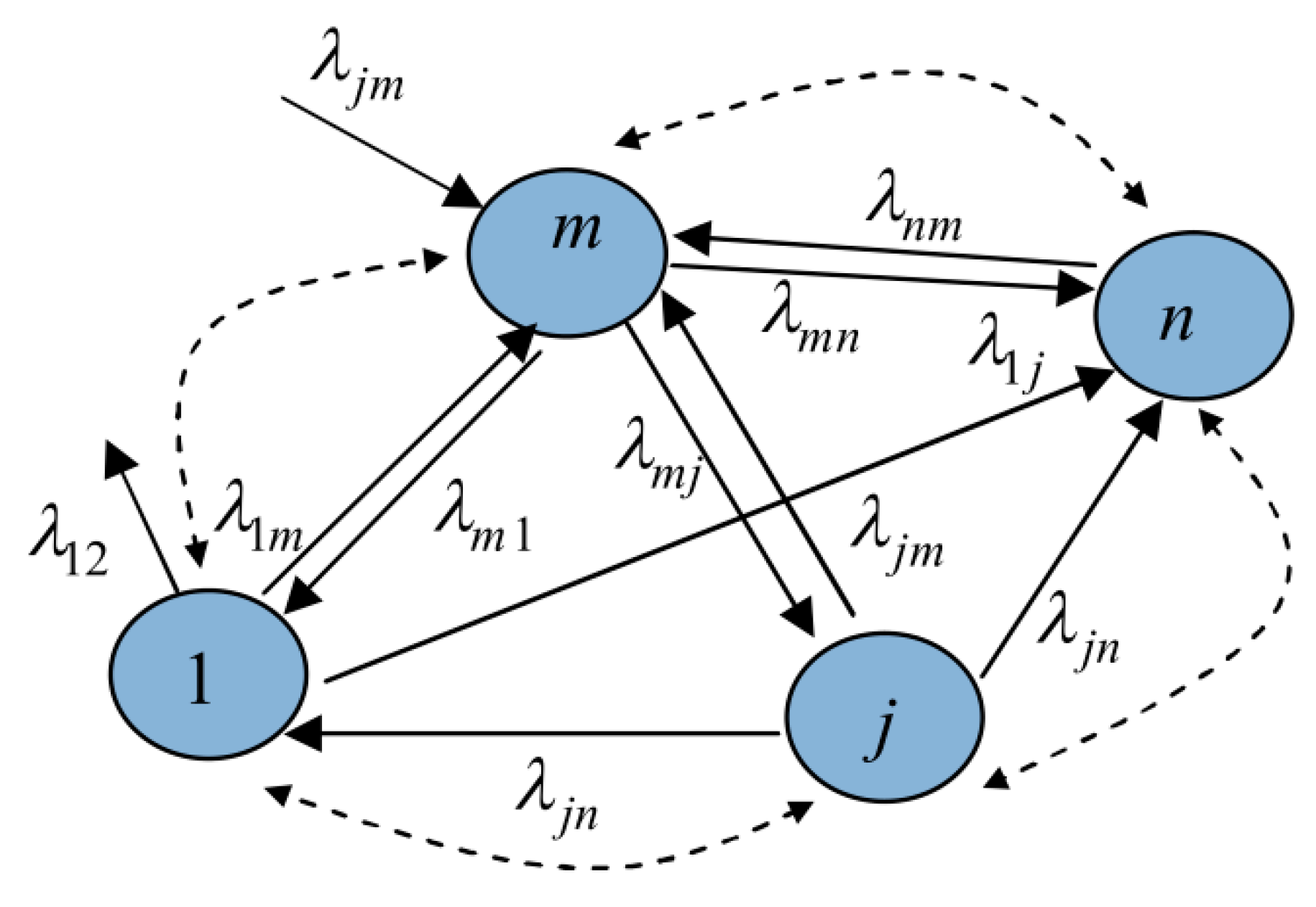
λ) in different modes, the Markov chain is used to determine the total MTTF of the system.
Figure 2 exemplifies a typical Markov chain, which is a stochastic process of
λ(t).According to
Figure 2, the probability that the system is in the
mth state at t moment (P
m(t)), is given by the following equation:
As stated in reference [
35], the reliability is the probability of a device performing its purpose adequately for the period of time intended under the operating conditions encountered. The MTTF is the average time during which the system successfully operates before it fails. This index is given by:
where
is the reliability of the system.
5. MTTF Analysis
In this paper, the single-phase, two-phase and three-phase interleaved boost converters are evaluated from the MTTF point of view. Also, the redundant-switch configurations are applied to the single-phase, two-phase and three-phase interleaved dc-dc converters. Four steps for the MTTF analysis are considered as follow:
Step 1: The MTTF curves for the parallel-switch-based and standby-switch-based single-phase converter are extracted. The obtained curves are illustrated as triangular fuzzy memberships.
Step 2: The fuzzy curves related to the parallel-switch-based and standby-switch-based two-phase converter are traced based on the obtained fuzzy-MTTF functions.
Step 3: With respect to the results obtained from the two previous steps and the three-phase operation condition, fuzzy-based MTTF curves are extracted.
Step 4: The fuzzy results are defuzzied to real values. This step provides a fair comparison to analyse the reliability of the considered converters in different modes.
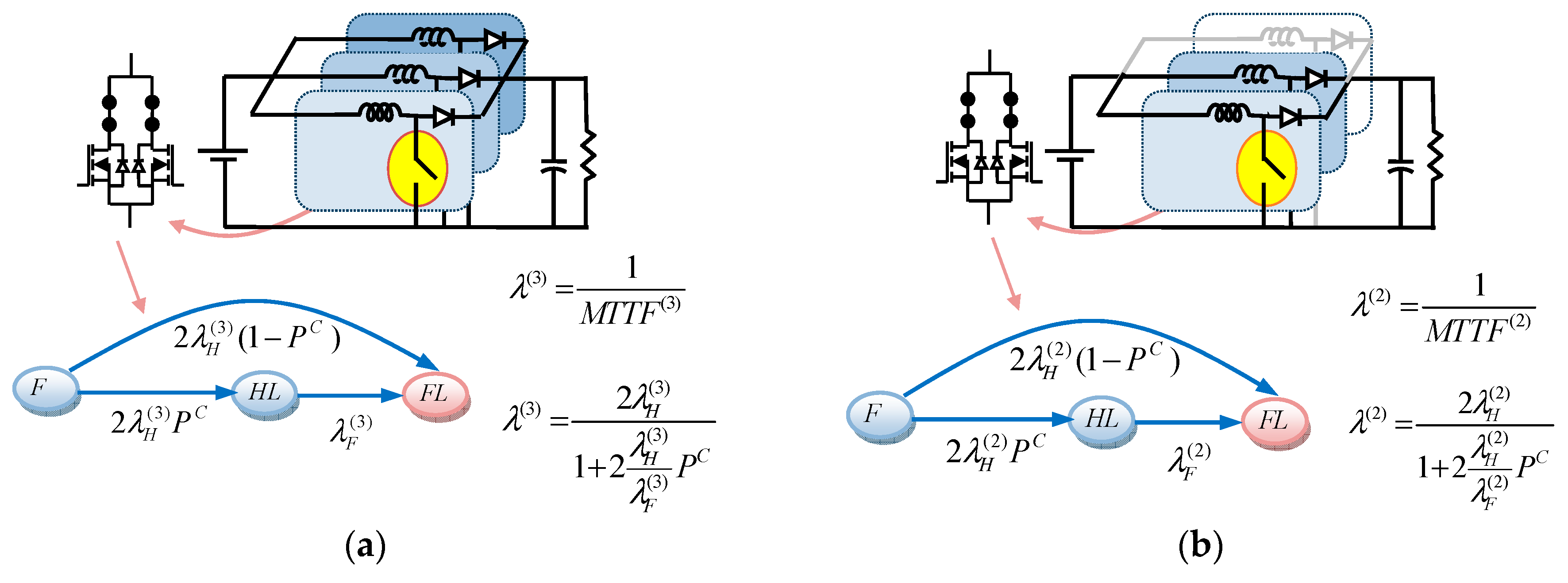
The Markov reliability modes of a three-phase converter with parallel-switch and standby-switch configurations are shown in
Figure 3. As shown in these figures, four states can be identified as follows:
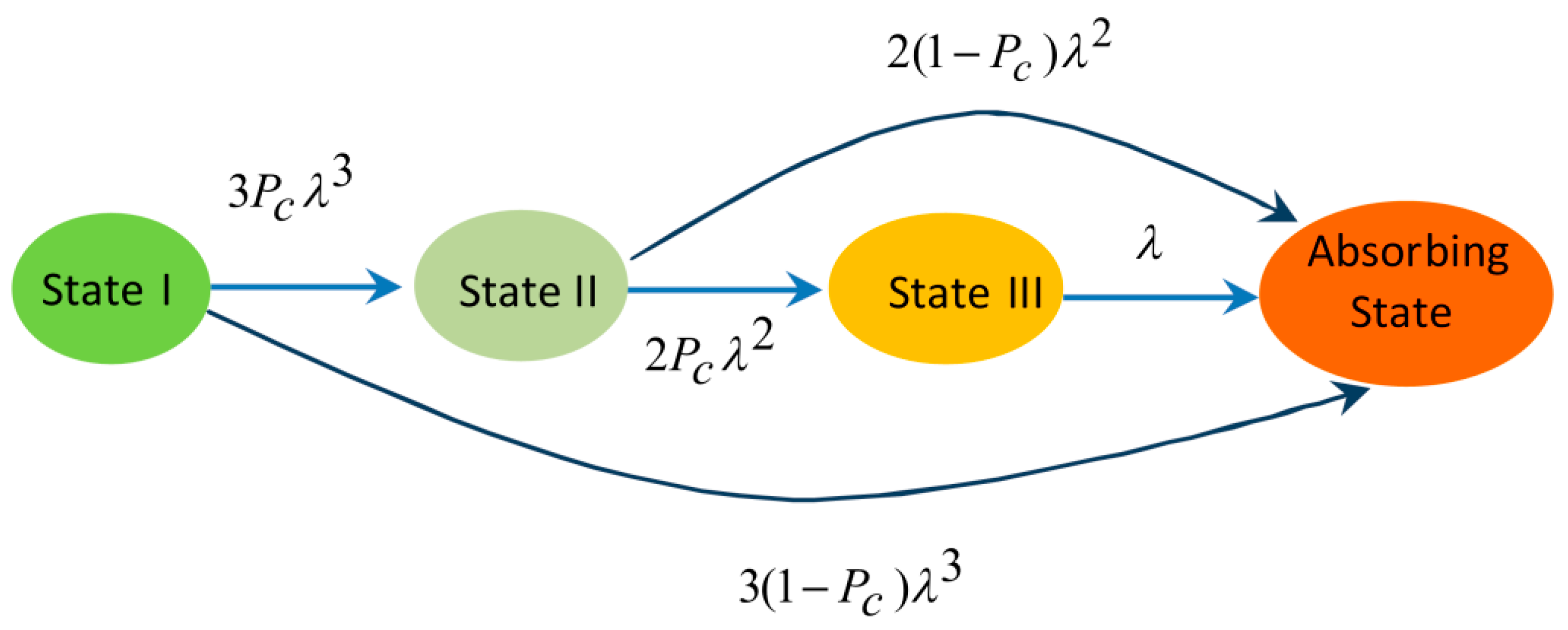
The overall Markov model of the considered converter is shown in
Figure 4. In the shown Markov model, the failure rate of a
k-phase converter is
, which is a constant value. The probability of successful operation of the fault-managing system is considered
. For example, as shown in
Figure 4, the transition rate from three-phase-converter state to two-phase-converter state is
. If the fault-managing system fails, the probability of the transition from three-phase-converter state to the absorbing state is
.
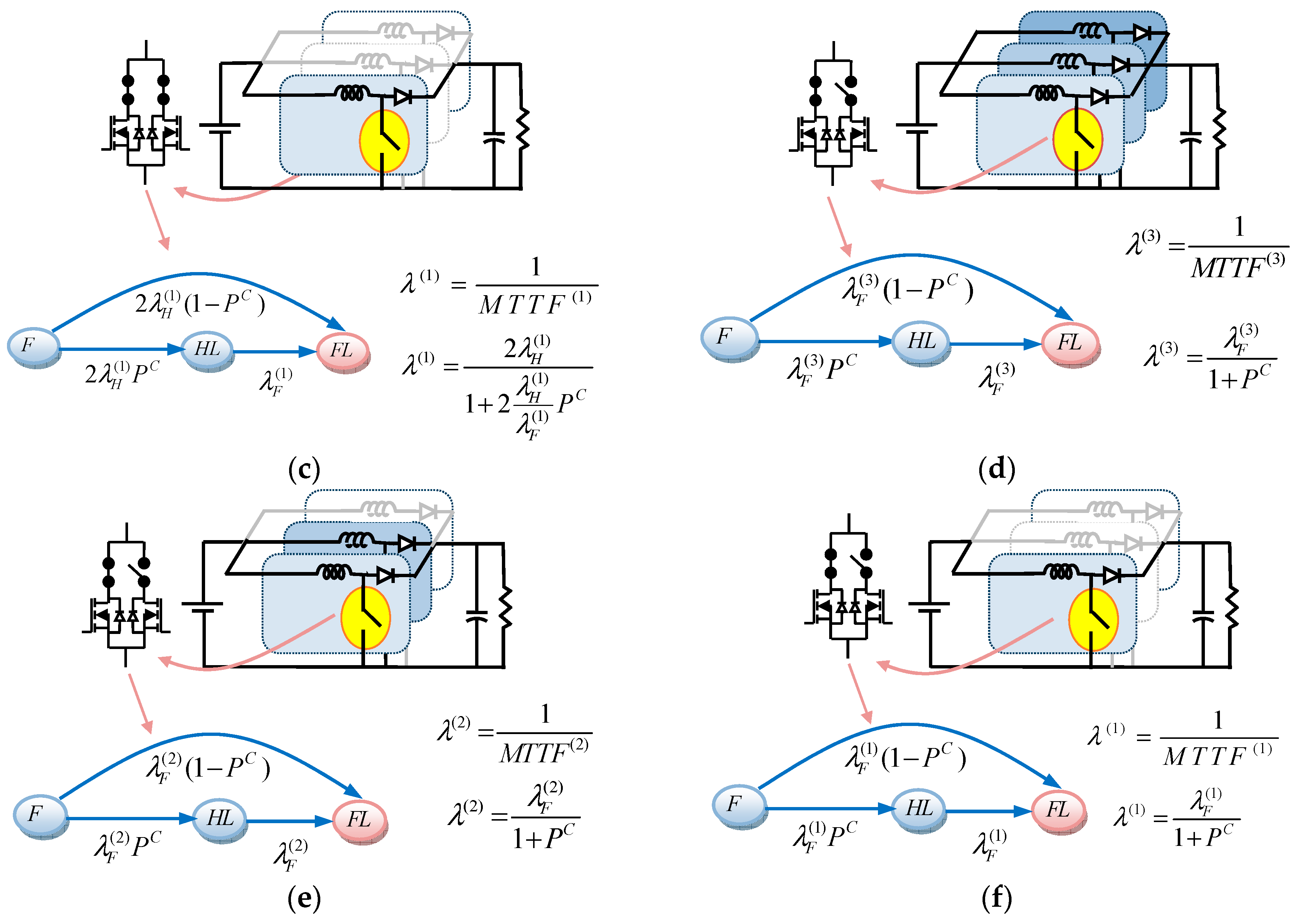
The MTTF of the single-phase and two-phase converters can be evaluated by referring to
Figure 4. The Markov model of the two-phase operation can be obtained by assuming
. As the same, the Markov model of the single-phase converter is obtained by considering
, and
. With respect to Equations (2)–(4), the junction temperatures and temperature factors of the switches in the studied converters are listed in
Table 1. By using these values, the MTTFs of the phases can be easily calculated. In general, three failure rates, which are seen in
Figure 3, are described as follows:
: Failure rate of a switch when the converter operates in k-phase mode, and the two parallel-switches conduct the phase current in parallel state;
: Failure rate of a switch when the converter operates in k-phase mode and only one of the standby-switches conducts the phase current;
: Probability of successful operation of the fault-managing system.
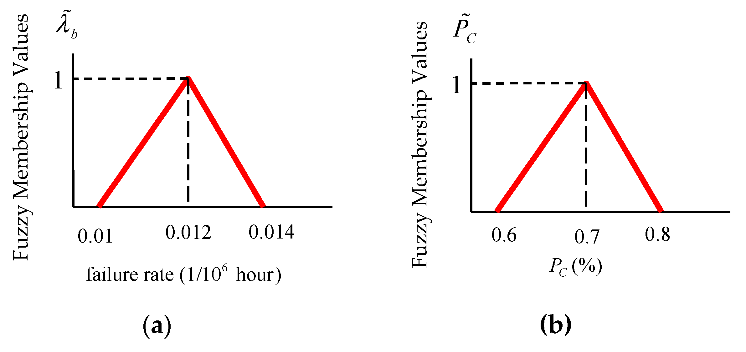
As shown in
Figure 5, the basic failure rate is considered as a fuzzy function The triangular memberships depend on three constant parameters a, b, and c, (a = 0.01, b = 0.012, and c = 0.014 for the basic failure curve and a = 0.6, b = 0.7 and c = 0.8 for the probability of successful operation of the fault managing system curve), according to
Table 1 and the basic failure rate, the failure rates of power switches in different redundant configuration can be obtained. As seen in
Figure 3, to calculate MTTF of a single-phase, two-phase and three-phase converter,
,
,
,
,
, and
must be determined. In these parameters, superscript 1,2,3 show the operation mode of the converter, i.e., single-phase, two-phase and three-phase states. Subscript
F and
H show the states of the switch that conducts either half the current of a phase or the whole of it, respectively. These parameters are fuzzy and can be extracted as follows:
In order to calculate the MTTF of the single-phase, two-phase and three-phase converter, referring to
Figure 3, the probability of successful operation of the fault-managing system is defined in
Table 2 where the differential equations for reliability analysis are given as follow:
The reliability functions of the three-phase converters can be obtained as follows:
Regarding Equation (5), (11), and (12), the MTTF of the three-phase converter is given by:
Similarly, the MTTF functions of the two-phase and single-phase converters are extracted by Equation (14) and (15), respectively.
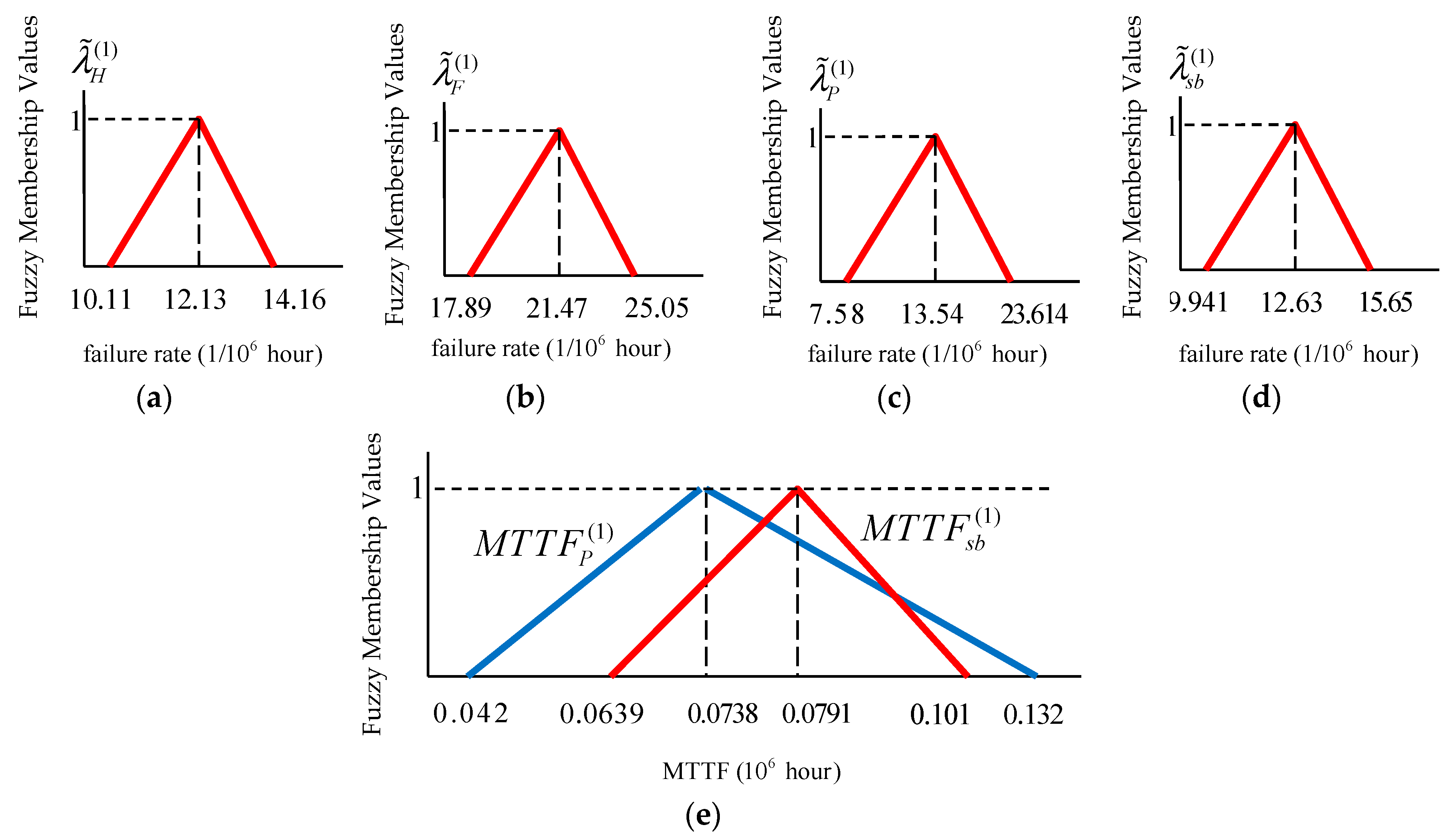
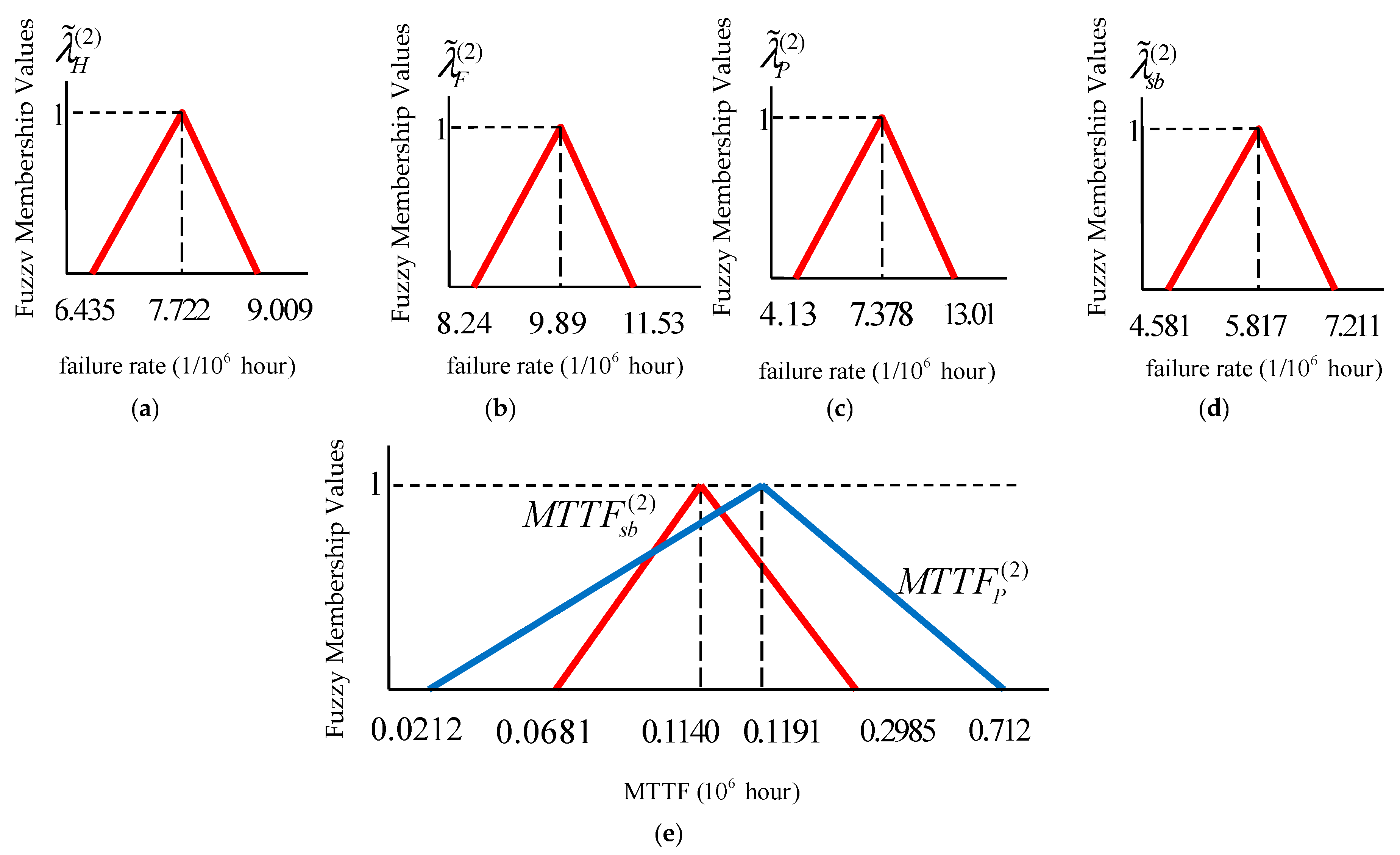
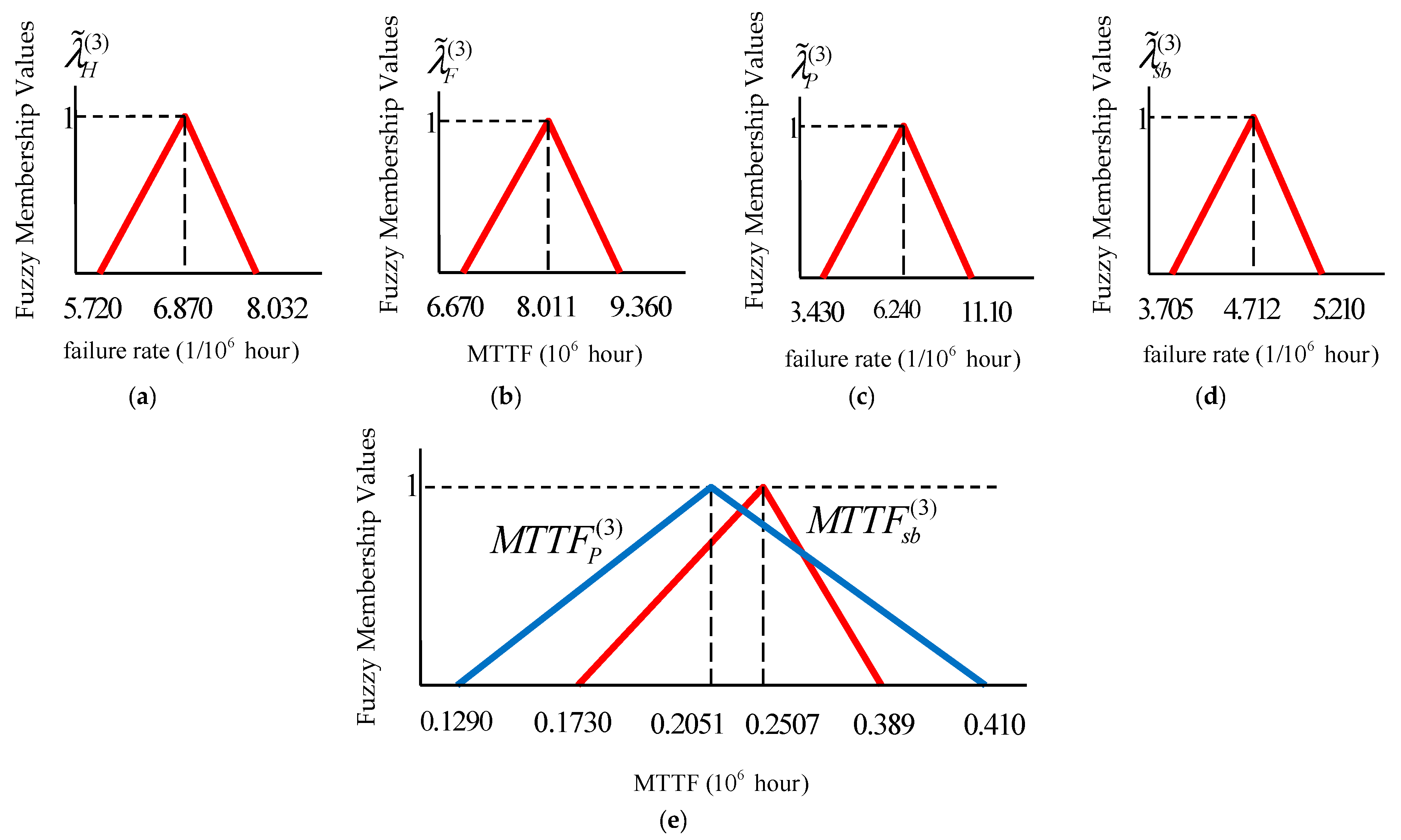
The fuzzy memberships of the switches are used to extract the fuzzy curves of the redundant-switch configuration. According to the obtained triangular functions, the MTTF functions of the converters can be extracted through
Figure 6,
Figure 7 and
Figure 8. By referring to Equation (9) and (10), and
Figure 5a, the fuzzy curve of the failure rate for each single switch in the parallel-switch and standby-switch configurations are obtained. The results are shown in
Figure 6a,b (for standby and parallel switches in the single-phase mode, respectively),
Figure 7a,b (for standby and parallel switches in the two-phase mode, respectively), and
Figure 8a,b (for standby and parallel switches in the single-phase mode respectively). Then, by considering the probability of the successful operation of the fault managing system (Pc) the fuzzy curves of the standby and parallel configurations are individually obtained. The results are shown in
Figure 6c,d (for standby and parallel configurations in the single-phase mode, respectively),
Figure 7c,d (for standby and parallel configurations in the two-phase mode, respectively), and
Figure 8c,d (for standby and parallel configuration in the single-phase mode, respectively). Finally, the fuzzy curves of the MTTF of different modes are extracted. The results are shown in
Figure 6e (for single-phase mode),
Figure 7e (for two-phase mode), and
Figure 8e (for three-phase mode).
The described fuzzy curves of the MTTFs show the probability of the healthy life of the converter equipped with the mentioned redundant structure. According to the results from fuzzy analysis, the standby-switch-based converters offer higher reliability compared to the parallel-switch-based converters. The MTTF of the standby-switch-based converter is in a narrower range than that of the parallel-switch-based ones. For example, for the two-phase converter, the probabilities of high and low MTTF for the standby-switch-based converter are small values. The medium MTTF value is more probable for the standby-switch-based converters than that for the parallel-switch-based ones.
As seen in fuzzy MTTF curves, it is probable that under certain conditions the MTTF of an n-phase converter is lower than that of a (n−1)-phase converter. To sum up, employing a proper fault-managing strategy makes it possible to prolong the MTTF of an n-phase converter in a way that it exceeds the MTTF of an (n−1)-phase converter.
Mapping the fuzzy numbers to a real number is the final step in fuzzy-based reliability evaluation. The defuzzified central (
) of triangular fuzzy numbers
can be determined by Equation (16). The results of the defuzzified values of the considered converters are provided in
Table 2.
According to
Table 2, it can be concluded that:
Standby-switch-based converter is suitable for three-phase and single-phase operation mode.
The MTTF of the three-phase converter is lower than that of the parallel-switch-based two-phase converter. Hence, the parallel-switch-based two-phase converter offers the highest reliability level.
For instance, the overall MTTF of the standby-switch-based converter in three-phase operation mode is 0.279 (106 h). This means that, regarding all the uncertainties, the mean life span of the converter in this operation mode is approximately 32 years ((0.297 × 10⁶)/(365 × 2)).
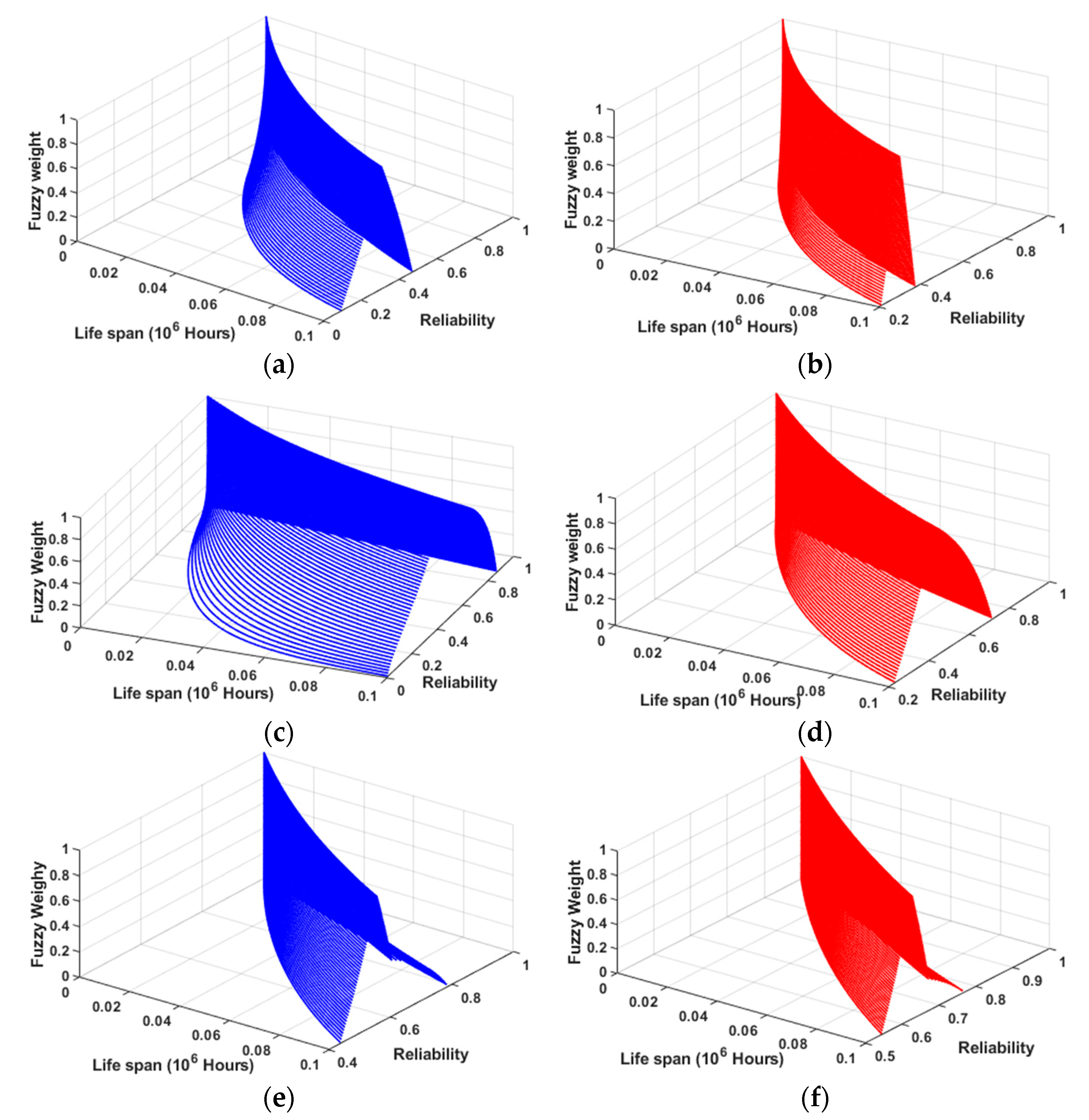
It is worthwhile to show the reliability of the redundant-switch converters as a function of time. To do so, the reliability curves of the converters, with respect to the obtained fuzzy MTTF memberships, against the life span are plotted in
Figure 9. In these figures, the reliability functions with their fuzzy weights are shown. The reliability curves of the parallel-switch-based converters (blue curves) are in a wider range than that of the standby-switch-based ones (red curves).
6. Simulation and Experimental Results
In this section, simulation results, obtained in Matlab/Simulink, and the experimental results, extracted from a lab-scaled prototype, are provided to verify the performance of the redundant-switch based converter. The characteristics of the employed elements are listed in
Table 3. For brevity only the commercial name of the components are listed in this table; however, the detail information can be found in the datasheets.
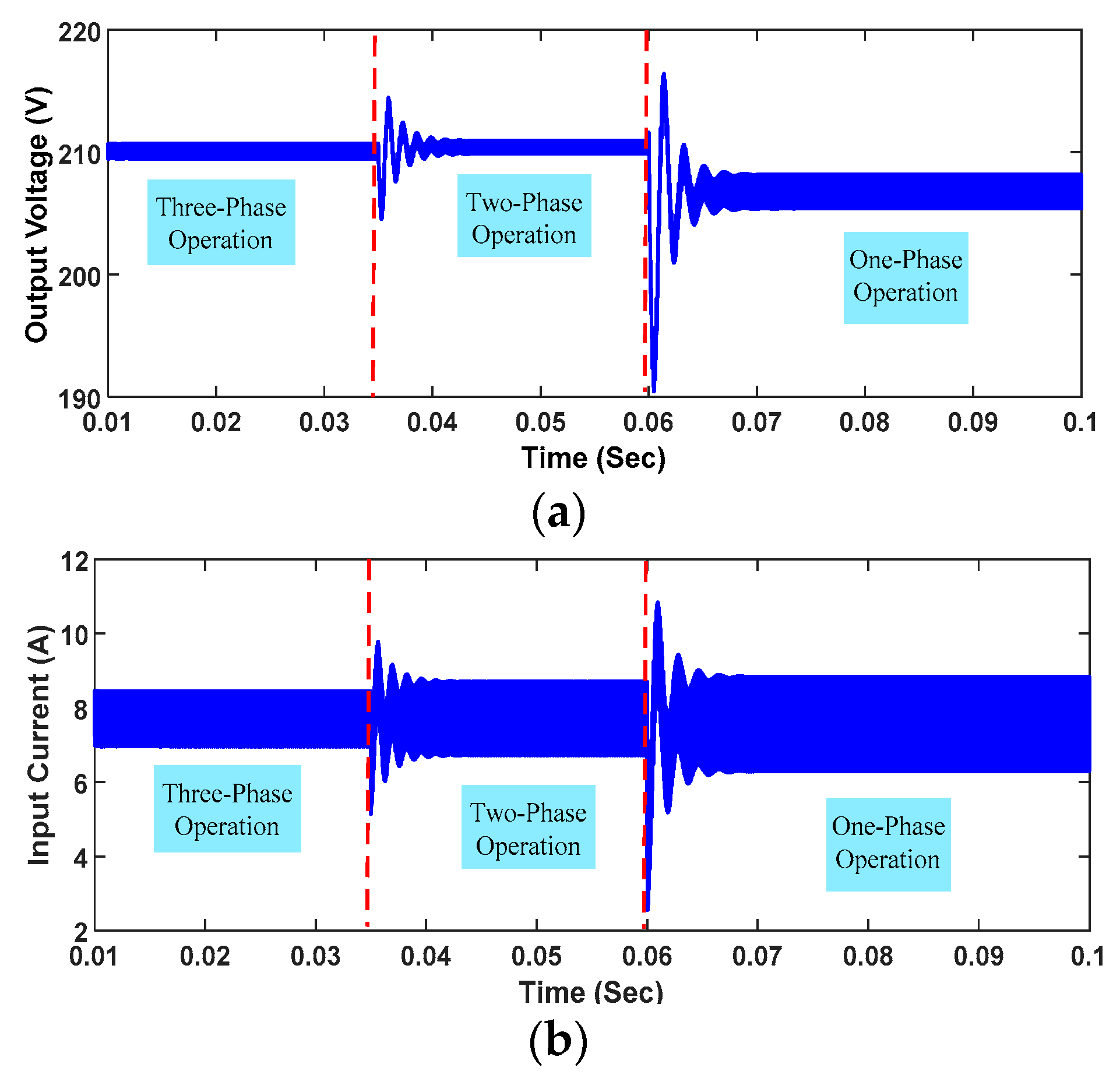
To substantiate better reliability, it is better to examine the dynamic behavior of the converter under a condition that one interleaved phase is out of operation. When one of the phases is out of operation, the faulty phase should be bypassed so that the other phases can continue to function and guarantee the normal operation of the converter. In order to test the performance of the converter under faulty conditions, two faults are exerted to two of the phases in different instances. The first and second faults are considered to happen at 35 ms and 60 ms, respectively. Under the first faulty condition, the faulty phase should be bypassed and the converter should proceed to operate with the remaining phases. In the healthy mode of a three-phase converter, the switches are symmetrically triggered by 120 degree phase-shift to guarantee a smooth current at the input side. When a fault occurs in one of the phases, the converter is reconfigured from three-phase to two-phase to fend off the fault effects. Additionally, to avoid asymmetric switching, the switches should be triggered by 180 degree phase-shift instead of 120 degree phase-shift. However, this will cost a higher input current ripple and output voltage. To prove the ability of the considered converter in the mentioned operation modes, simulation results of the output voltage and input current are shown in
Figure 10a,b respectively. As predicted, due to the reduction of the phase, the ripple of the input current and output voltage increase as the faulty phases are bypassed to react against the faults.
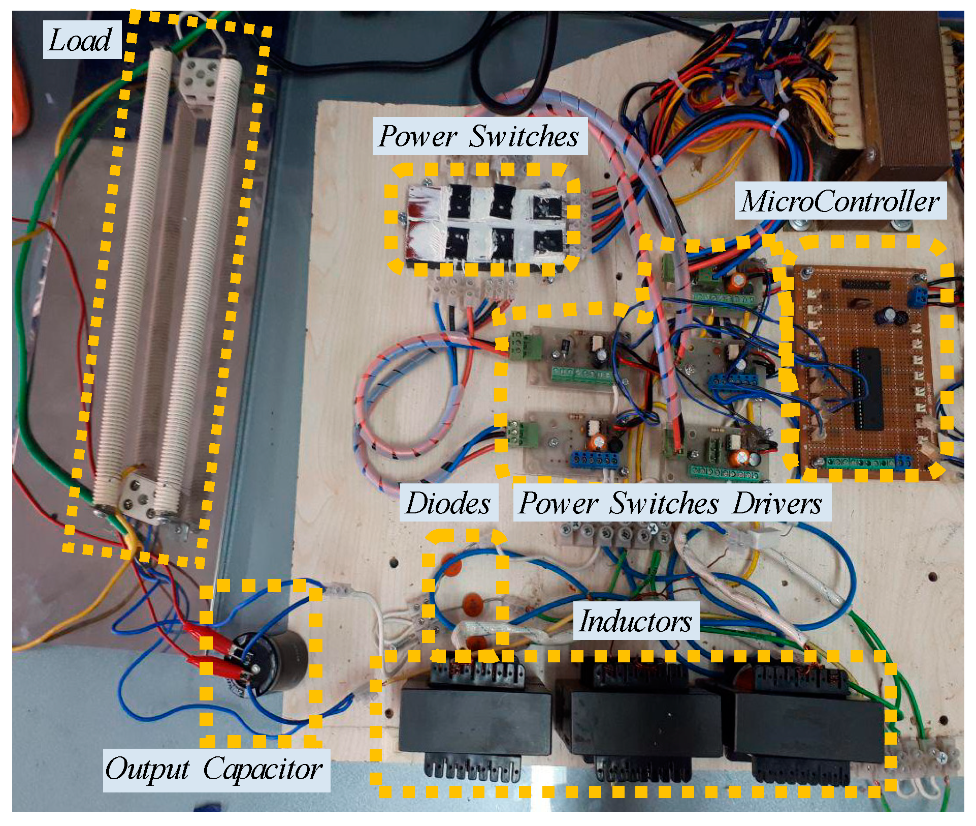
The lab-scaled prototype, which is shown in
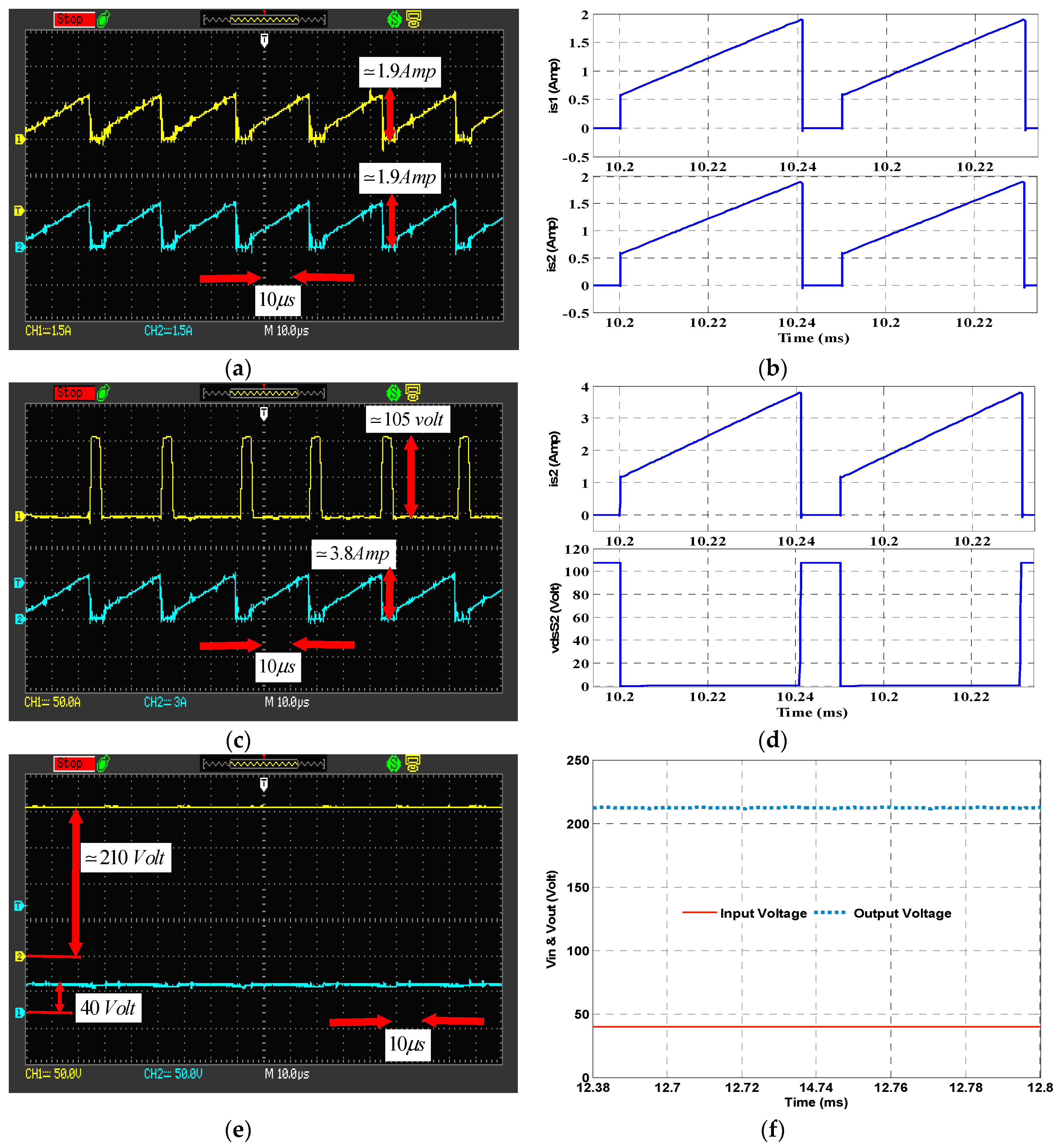
Figure 11, is a 300 W three-phase interleaved dc-dc converter that is equipped with redundant-switch (the parallel-switch and standby-switch) configurations. The experimental and simulation results of the considered redundant configuration are shown in
Figure 12. As seen in
Figure 12a,b, the parallel-switches carry half the phase current, and thus it includes lower conduction power losses. The voltage across the switches is equal to the output voltage. Since the switching power loss depends on the voltage across the switches and all the switches tolerate the same voltage, the switching power loss of the switches are the same.
Figure 12c,d shows the experimental and simulation results of the voltage of the standby-switch along with the current passing through the active switch in the standby-switch configuration, respectively. Furthermore, the input current and output voltage of the converter are shown in
Figure 12e,f, (
Figure 12e shows the experimental results and
Figure 12f shows the simulation results). Since this work is not aimed at improving the performance of the studied converter, the components and measuring devices are chosen arbitrarily. That is why the distortions and noises appear in experimental results. However, it is possible to extract more qualitative results by using some suitable components and precise measuring devices. Despite the noise and spikes in experimental results, the overall waveforms of experimental and simulation results are in full agreement with each other.

 ,
, 


