Article

Non-Contact Ultrasonic Inspection of Impact Damage in Composite Laminates by Visualization of Lamb wave Propagation

1
National Metrology Institute of Japan, National Institute of Advanced Industrial Science and Technology (AIST), 1-1-1 Umezono, Tsukuba, Ibaraki 305-8568, Japan
2
Department of Aeronautics and Astronautics, Kyushu University, 744 Motooka, Nishi-ku, Fukuoka 819-0395, Japan
*
Author to whom correspondence should be addressed.
Appl. Sci. 2019, 9(1), 46; https://doi.org/10.3390/app9010046
Submission received: 27 November 2018 / Revised: 12 December 2018 / Accepted: 21 December 2018 / Published: 24 December 2018
(This article belongs to the Special Issue Nondestructive Testing in Composite Materials)

Abstract

:
This study demonstrates a rapid non-contact ultrasonic inspection technique by visualization of Lamb wave propagation for detecting impact damage in carbon fiber reinforced polymer (CFRP) laminates. We have developed an optimized laser ultrasonic imaging system, which consists of a rapid pulsed laser scanning unit for ultrasonic generation and a laser Doppler vibrometer (LDV) unit for ultrasonic reception. CFRP laminates were subjected to low-velocity impact to introduce barely visible impact damage. In order to improve the signal-to-noise ratio of the detected ultrasonic signal, retroreflective tape and a signal averaging process were used. We thus successfully visualized the propagation of the pulsed Lamb A0 mode in the CFRP laminates without contact. Interactions between the Lamb waves and impact damage were clearly observed and the damage was easily detected through the change in wave propagation. Furthermore, we demonstrated that the damage could be rapidly detected without signal averaging. This method has significant advantages in detecting damage compared to the conventional method using a contact resonant ultrasonic transducer due to the absence of the ringing phenomenon when using the LDV.

Graphical Abstract

1. Introduction

Carbon fiber reinforced polymer (CFRP) laminates are increasingly being applied to structural components in aircrafts and automobiles to improve fuel efficiencies, due to its lightweight, superior strength and stiffness. Composite structures in these safety-critical applications must be inspected to ensure safety and reliability and to prevent catastrophic failure. Among the various types of damage, internal damage from low-velocity impact is the most common type found in composite structures. This damage is easily induced from things as simple as tools being dropped during maintenance. Damage presents in the form of matrix cracks, delamination, and fiber breakage. Moreover, this damage is barely visible to the naked eye on the structure’s surface, which is explained by the term, “barely visible impact damage (BVID)”. Delamination in particular, must be detected during inspection processes, as it causes a significant loss of compressive strength. Current inspection practices employ non-destructive testing (NDT) techniques such as X-ray or ultrasonic C-scan to identify delamination. However, these techniques are very time-consuming and expensive for inspecting large structures. Therefore, a new, non-contact NDT technique to detect damage quickly, reliably, and automatically is required by industry. Should any damage be found, the conventional method can be applied to evaluate the damage in detail.
Ultrasonic waves propagate as Lamb waves in thin plate-like structures such as aircraft skins and automobiles bodies. They have significant potential for large-area, non-destructive inspection because they have a long propagation distance and allow the whole volume of the material between the transmitting and receiving transducers to be inspected. Therefore, Lamb wave inspection has been extensively applied for the detection of delamination in CFRP laminates in the literatures [1,2,3,4,5,6,7,8]. Recently, phased array ultrasonic techniques have also been developed for large-area inspection [9,10]. However, interpretation of the detected Lamb waves is challenging due to their dispersive nature, as well as the presence of multiple modes and scattered waves from the edge of the components.
On the other hand, by visualizing the ultrasonic waves propagating in an actual structure, the appearance of the additional scattered waves can be used to directly observe damage—without having to interpret the complicated measured waveforms. Ultrasonic wave propagation visualization is thus very effective for reliable damage inspection. We have previously developed a technique for the visualization of ultrasonic wave propagation in general solid media [11], which uses a pulsed laser that scans an object for ultrasonic wave generation and a fixed contact receiver to provide a movie (or series of snapshots) of the propagating waves. Although this is not a “fully” non-contact technique, it operates excellently, enables quick inspection of objects of arbitrary shapes. We have applied it to the non-destructive inspection of various structural components and demonstrated its usefulness [12,13,14].
In recent times, the development of ultrasonic wavefield imaging techniques for detecting delamination in composite laminates has attracted notable attention. Measurement systems utilizing a combination of fixed and/or scanning sources and receivers have been proposed to obtain the Lamb wave propagation images [15,16,17,18,19,20,21,22]. However, limited research has been undertaken on complete non-contact ultrasonic wavefield imaging techniques. Park et al. [20] adopted a Nd: YAG pulse laser for ultrasonic wave generation and a laser Doppler vibrometer (LDV) for reception to obtain the wavefield of the Lamb wave in composite structures, and detected delamination and disbonding. However, further studies are still needed to improve, especially in relation to inspection time, inspection area and image quality.
In this study, we demonstrate a rapid non-contact ultrasonic inspection technique by visualization of Lamb wave propagation for detecting BVID in CFRP laminates. This optimized laser ultrasonic wavefield imaging system utilizes rapid pulsed laser scanning and LDV units to clearly visualize damage in impacted CFRP laminates. Measurement techniques are developed to improve the signal-to-noise ratio of the detected ultrasonic signals. Furthermore, we compare the proposed method to a conventional contact piezoelectric transducer method. Through this study, we demonstrate the efficiency and feasibility of the proposed technique for the non-contact inspection of composite structures.

2. Experimental Procedure
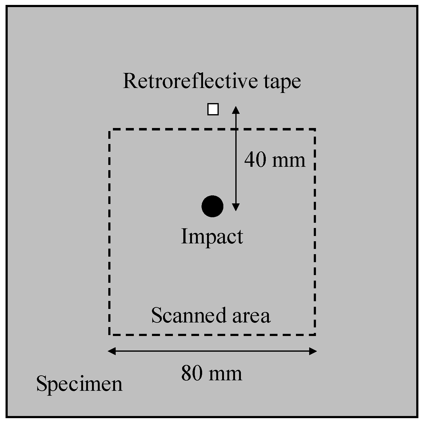
2.1. Specimens

The materials used were CFRP (TR380-G250SM, Mitsubishi Chemical, Tokyo, Japan) cross-ply and quasi-isotropic laminates with stacking sequences of [0/90]2S and [0/45/90/−45]S. The specimens had dimensions of 160 × 160 × 1 mm and were subjected to low-velocity impact with an energy of 6 J using a vertical drop-weight impact system (CREAST 9310, Instron, Norwood, MA, USA) to induce the BVID. A hemispherical impactor with a diameter of 20 mm was used. The impacted specimens were inspected using a water-immersion ultrasonic C-scan system (TT-UTCS01, Tsukuba Technology, Tsukuba, Japan). Square regions of 40 × 40 mm, which included the impacted positions, were scanned with an interval of 0.3 mm using a focused ultrasonic transducer with a resonant frequency of 10 MHz, diameter of 5 mm, and focal distance of 25 mm. Figure 1 shows the C-scan images for both specimens. Internal impact damages consisting of delamination of multiple interlayers were clearly detected, with dimensions of about 14 mm in the major axis and 9 mm in the minor axis. These BVIDs are the inspection targets of this study.

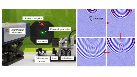
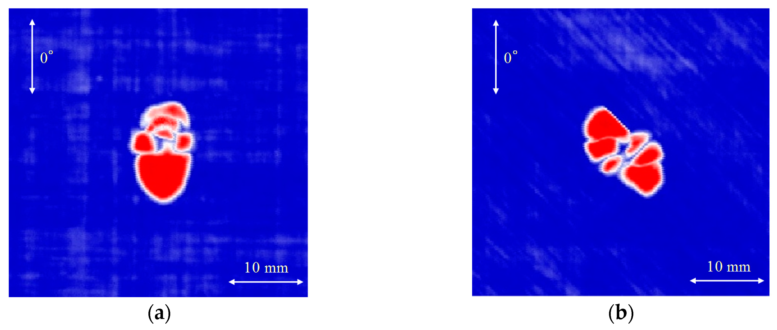
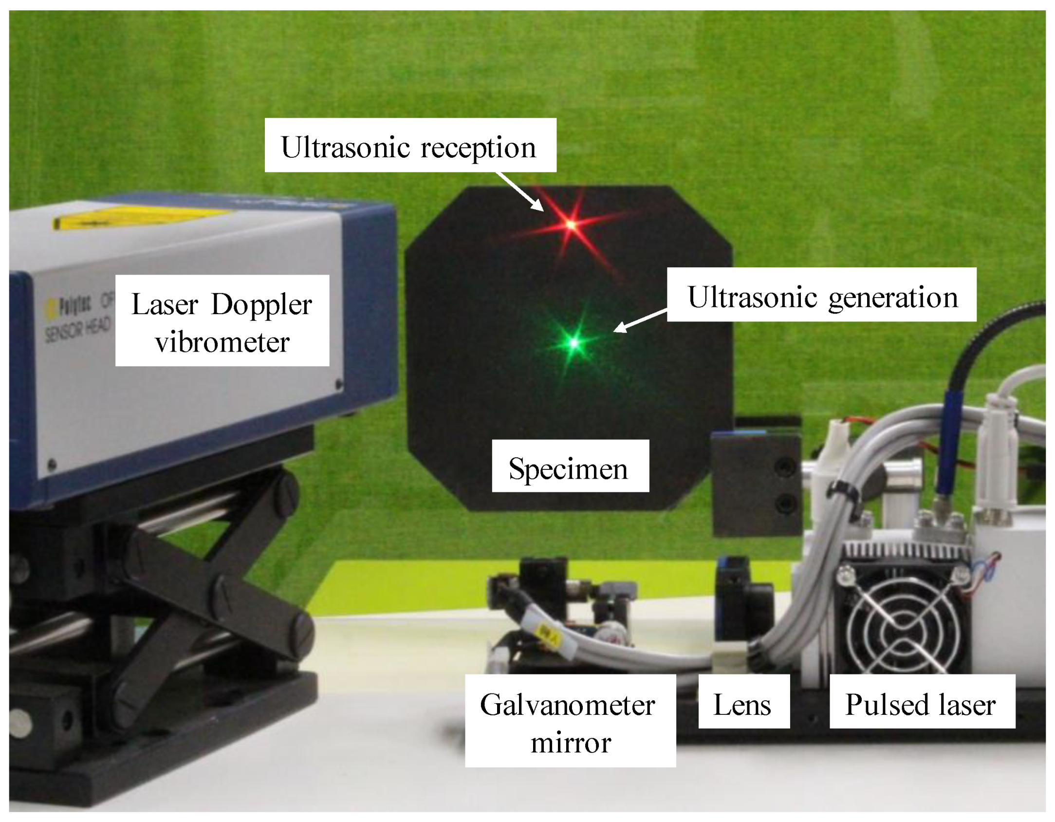
2.2. Non-Contact Laser Imaging System for Ultrasonic Wave Propagation

Figure 2 displays a photograph of the non-contact laser imaging system for visualizing ultrasonic wave propagation. This system consists of a rapid pulsed laser scanning unit for ultrasonic generation and a LDV unit for ultrasonic reception. Pulsed thermoelastic ultrasonic waves are generated by illuminating the specimen surface with a Q-switched Nd: YAG laser (Wedge-HB-1064-DB, Bright Solutions, Pavia, Italy) with a wavelength of 1064 nm, pulse width of 1.5 ns, maximum pulse energy of 2 mJ, and maximum repetition frequency of 2 kHz. The diameter of the laser beam is reduced by using a varifocal lens (APL-1050, Holochip, Hawthorne, CA, USA). The laser beam is scanned on the specimen surface using a computer-controlled galvanometer mirror (VM500+, Novanta, Bedford, MA, USA). A green laser beam with a wavelength of 532 nm is also illuminated for convenience, since the pulsed laser beam is invisible. The LDV system is used to receive the ultrasonic wave signals. It consists of a modular vibrometer (OFV-5000, Polytec, Waldbronn, Germany) and a sensor head (OFV-505-KA, Polytec, Waldbronn, Germany). A He-Ne continuous wave (CW) laser with a wavelength of 633 nm and energy of 2 mW is illuminated at a fixed position on the specimen surface, and the out-of-plane displacement at that position is measured based on the Doppler effect. The received signals are bandpass-filtered from 50 to 400 kHz using a variable-frequency filter (3628 Dual Channel Programmable Filter, NF, Yokohama, Japan) and stored in the computer through a high-speed digitizer (NI PCI-5124, National Instruments, Austin, TX, USA). A snapshot of the propagating waves at any given time is obtained by plotting the amplitude of each waveform at that time on a contour map. The snapshots can be continuously displayed in a time series to form a video of the waves propagating beneath the CW laser.

2.3. Non-Contact Ultrasonic Inspection

The specimens were vertically fixed at a position about 400 mm from the galvanometer mirror and LDV sensor head. As illustrated in Figure 3, laser scanning with an interval of 0.5 mm was performed in square regions of 80 × 80 mm. To improve the signal-to-noise ratio, each position was illuminated 30 times during the scanning and the 30 received signals were averaged. The pulse energy and scanning speed were set to about 0.6 mJ and 300 points/s, respectively, so that the laser illumination did not cause surface ablation. Due to the poor reflectivity of the CW laser, and the fact that the diameter of the laser beam at the specimen surface was about 50 µm, a 3 × 3 mm square of retroreflective tape (A-RET-T010, Polytec, Waldbronn, Germany) was attached to the specimen surface at the CW-laser illuminated position (40 mm from the impacted position) to improve the reflectivity. It should be noted that the scanning speed used in this study is estimated to be about 25 times faster than that in the previously reported technique [20,21].

3. Results

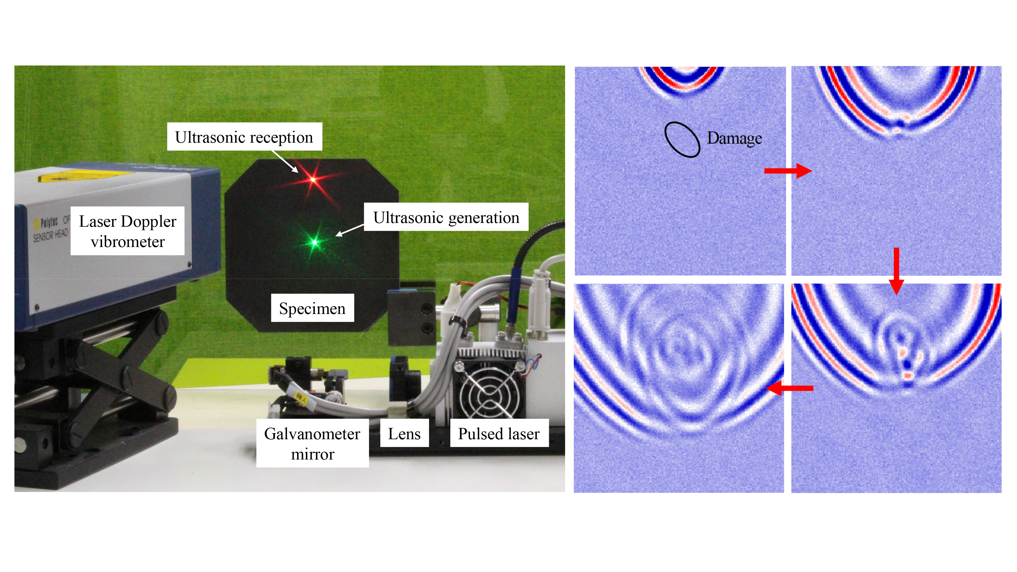
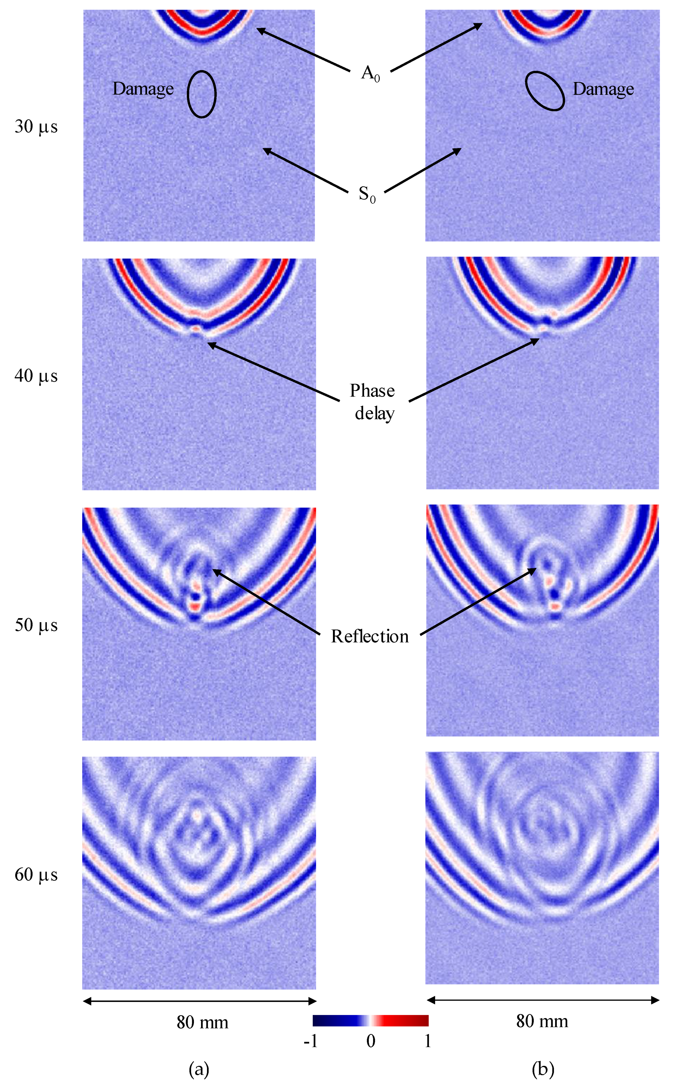
3.1. Non-Contact Ultrasonic Damage Inspection

Figure 4 depicts the visual results of the ultrasonic wave propagation for both specimens. The ellipses shown in the top figures demonstrate the approximate location and shape of the damage in each specimen. The ultrasonic waves propagate as Lamb waves in these thin CFRP laminates, and it was confirmed that only the first symmetric (S0) and first anti-symmetric (A0) modes exist in the low frequency range between 50 and 400 kHz by using the dispersion curve analysis program Disperse [23]. The faster S0 mode is almost invisible in the figure since the amplitude detected by the LDV was very low. On the other hand, the detected amplitude of the slower A0 mode was high enough for its propagation behavior with a pulsed shape to be clearly visualized. In both specimens, when the A0 mode reaches the damage, a phase delay is observed. Furthermore, following the phase delay, reflected waves from the damage are distinctly observed; the shape of the reflected wave strongly depends on that of the damage shown in Figure 1. It is very important that the detailed interactions between the Lamb wave and the impact-induced damage were clearly visualized, and that the damage was easily detected using the proposed non-contact laser imaging method for ultrasonic-wave propagation. These results demonstrate the drastic improvement in inspection time without losing the quality in the ultrasonic images [20,21].

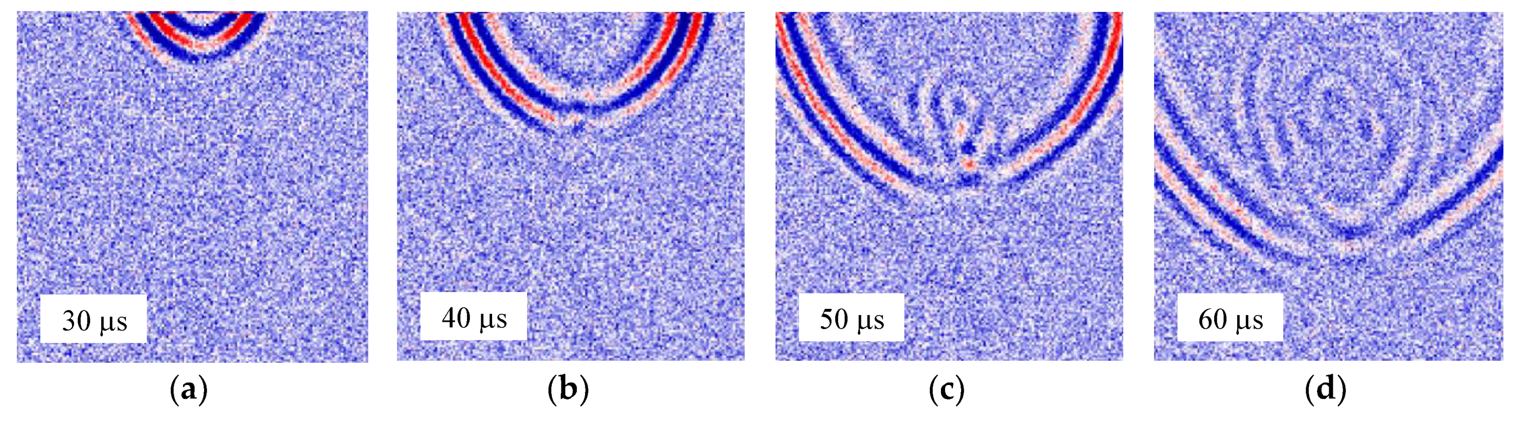
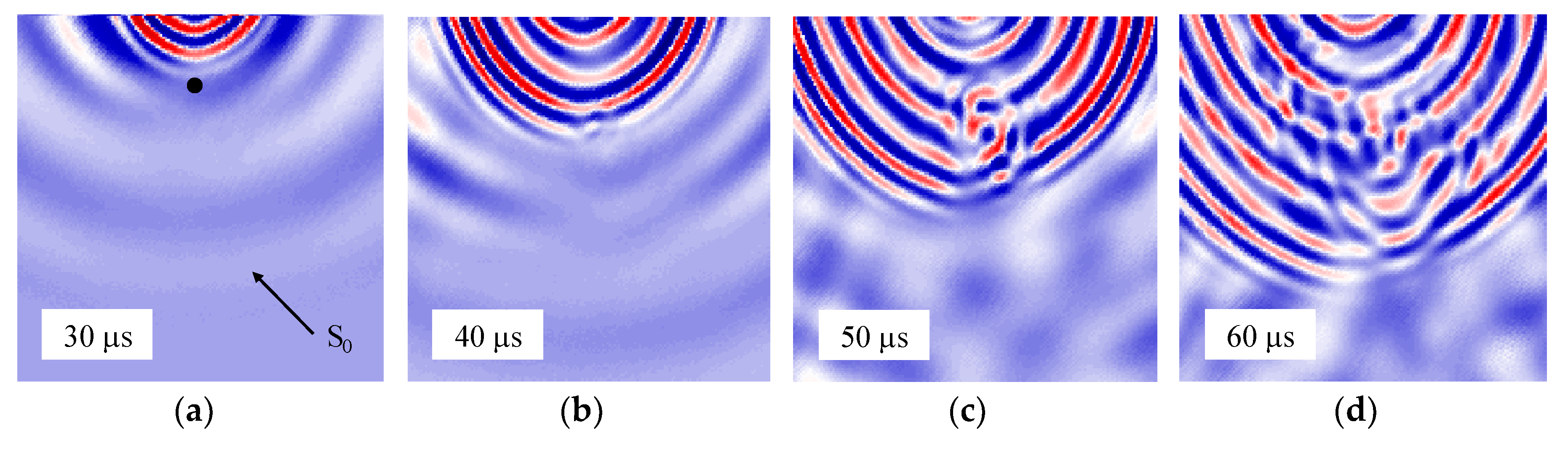
3.2. Rapid Ultrasonic Damage Detection

In order to achieve non-contact inspection by visualization of ultrasonic wave propagation, it is necessary to use the LDV to receive the low-energy ultrasonic waves induced by the pulsed laser. However, the LDV sensitivity is much lower than that of conventional contact transducers. We therefore used a time-consuming signal averaging process to improve the signal-to-noise ratio. Consequently, clear images of the pulsed A0 mode propagation waves were obtained as shown in Figure 4. On the other hand, there is a high demand for rapid non-destructive inspection techniques that can quickly indicate whether or not damage is present. Figure 5 depicts the visual results of ultrasonic wave propagation for the CFRP quasi-isotropic specimen without signal averaging. The obtained images are noisier than those in Figure 4b; however, the presence of the damage can still easily be identified through the reflected waves. Furthermore, we confirmed that non-contact and quick inspection is compatible with the impacted specimen used in this study.
Figure 6 compares ultrasonic images at 55 μs for the CFRP quasi-isotropic specimen for various averaging times. As a result, the images become clearer with increasing averaging time (i.e., increasing scanning time). The averaging time should be selected according to the damage (type, size), objective materials, inspection time, inspection resolution, and so on. Moreover, the signal-to-noise ratio could be drastically improved and inspected quickly using the mid-infrared laser developed by Hatano et al. [24], as it can generate significantly larger ultrasonic amplitude in CFRP laminates than the conventional Nd: YAG laser [25].

4. Discussion

To identify how the proposed non-contact method compares to the conventional methods [11,12,13,14], we analyzed the same specimen using a contact ultrasonic transducer instead of the LDV. Figure 7 depicts the visual results of the ultrasonic-wave propagation for the CFRP quasi-isotropic specimen using the conventional method. The contact ultrasonic receiver had a resonant frequency of 200 kHz (M204A, Fuji Ceramics, Fujinomiya, Japan) and was glued to the specimen surface at the position of the CW laser illumination. The received signals were amplified by a preamplifier (A1201, Fuji Ceramics, Fujinomiya, Japan) and bandpass-filtered from 50 to 400 kHz before being stored on the computer.
The sensitivity of the transducer is high enough for the S0 mode to be observed. Similarly to the result shown in Figure 4, a phase delay is observed when the A0 mode reaches the damage. However, the visualized incident wave of the A0 mode is displayed as a continuous wave rather than a pulsed wave, causing the wave reflected from the damage to interact with the incident wave, obstructing its clear identification. Figure 8 compares the waveforms received by both methods when the pulsed laser illuminates the position shown by the black dot in Figure 7a. As expected, using the LDV unit, the incident wave of the A0 mode has a pulsed shape; therefore, the wave reflected from the damage can be identified. In contrast, when using the contact transducer, the S0 mode is observed and followed by a ringing phenomenon in the A0 mode due to the resonance of the piezoelectric transducer. Due to the ringing, the reflected wave cannot be identified. This ringing often causes difficulty in detecting reflected waves from small defects or damage, and additional filtering becomes necessary for detailed analysis of the damage. In contrast, the LDV purely measures the out-of-plane displacement of the pulsed ultrasonic wave and thus does not cause such ringing. It should be noted that this is another significant advantage of the proposed non-contact method for easy inspection.

5. Conclusions

This study demonstrated a rapid non-contact ultrasonic inspection technique by visualization of Lamb wave propagation for detecting barely visible impact damage in CFRP laminates. Our laser ultrasonic imaging system consists of a rapid pulsed laser scanning unit for ultrasonic generation and a LDV unit for ultrasonic reception. The signal-to-noise ratio of the ultrasonic signal was improved using retroreflective tape and a signal averaging process, and we successfully visualized the propagation of the pulsed Lamb A0 mode in CFRP laminates. The interactions between the Lamb waves and the impact damage were clearly observed and the damages were easily detected through changes in wave propagation. Furthermore, we demonstrated that damage could be rapidly detected without applying signal averaging. The proposed method using the LDV has significant advantages in detecting damage compare to the conventional resonant ultrasonic transducer method. However, further improvement of the signal-to-noise ratio is necessary to inspect large areas and to detect smaller defects. In addition, we plan in the near future to establish an ultrasonic wavefield image dataset and to develop an automated image analysis system for damage detection in composite structures using machine learning.

Author Contributions

Conceptualization, N.T.; investigation, N.T. and S.Y.; methodology, J.Y. and W.K.; writing—original draft preparation, N.T.; writing—review and editing, J.Y., W.K. and S.Y.

Funding

This article is based on results obtained from a project commissioned by the New Energy and Industrial Technology Development Organization (NEDO).

Conflicts of Interest

The authors declare no conflict of interest.

References

  1. Guo, N.; Cawley, P. The interaction of Lamb waves with delaminations in composite laminates. J. Acoust. Soc. Am. 1993, 94, 2240–2246. [Google Scholar] [CrossRef]
  2. Hayashi, T.; Kawashima, K. Multiple reflections of Lamb waves at a delamination. Ultrasonics 2002, 40, 193–197. [Google Scholar] [CrossRef]
  3. Diamanti, K.; Hodgkinson, J.M.; Soutis, C. Detection of low-velocity impact damage in composite plates using Lamb waves. Struct. Health Monit. 2004, 3, 33–41. [Google Scholar] [CrossRef]
  4. Toyama, N.; Takatsubo, J. Lamb wave method for quick inspection of impact-induced delamination in composite laminates. Compos. Sci. Technol. 2004, 64, 1293–1300. [Google Scholar] [CrossRef]
  5. Su, Z.; Ye, L.; Lu, Y. Guided Lamb waves for identification of damage in composite structures: A review. J. Sound Vib. 2006, 295, 753–780. [Google Scholar] [CrossRef]
  6. Ramadas, C.; Padiyar, J.; Balasubramaniam, K.; Joshi, M.; Krishnamurthy, C.V. Lamb wave based ultrasonic imaging of interface delamination in a composite T-joint. NDT&E Int. 2011, 44, 523–530. [Google Scholar] [CrossRef]
  7. Liu, Z.; Yu, H.; Fan, J.; Hu, Y.; He, C.; Wu, B. Baseline-free delamination inspection in composite plates by synthesizing non-contact air-coupled Lamb wave scan method and virtual time reversal algorithm. Smart Mater. Struct. 2015, 24, 045014. [Google Scholar] [CrossRef] [Green Version]
  8. Feng, B.; Ribeiro, A.L.; Ramos, H.G. Interaction of Lamb waves with the edges of a delamination in CFRP composites and a reference-free localization method for delamination. Measurement 2018, 122, 424–431. [Google Scholar] [CrossRef]
  9. Taheri, H.; Du, J.; Delfanian, F. Experimental observation of phased array guided wave application in composite materials. Mater. Eval. 2017, 75, 1308–1316. [Google Scholar]
  10. Taheri, H. Utilization of Non-Destructive Testing (NDT) Methods for Composite Material Inspection (Phased Array Ultrasonic). Master’s Thesis, South Dakota State University, Brookings, SD, USA, August 2014. [Google Scholar]
  11. Takatsubo, J.; Wang, B.; Tsuda, H.; Toyama, N. Generation laser scanning method for the visualization of ultrasounds propagating on a 3-D object with an arbitrary shape. J. Solid Mech. Mater. Eng. 2007, 1, 1405–1411. [Google Scholar] [CrossRef]
  12. Yashiro, S.; Takatsubo, J.; Miyauchi, H.; Toyama, N. A novel technique for visualizing ultrasonic waves in general solid media by pulsed laser scan. NDT&E Int. 2008, 41, 137–144. [Google Scholar] [CrossRef]
  13. Yashiro, S.; Takatsubo, J.; Toyama, N. An NDT technique for composite structures using visualized Lamb-wave propagation. Compos. Sci. Technol. 2007, 67, 3202–3208. [Google Scholar] [CrossRef]
  14. Toyama, N.; Yamamoto, T.; Urabe, K.; Tsuda, H. Ultrasonic inspection of adhesively bonded CFRP/aluminum joints using pulsed laser scanning. Adv. Compos. Mater. 2017. [Google Scholar] [CrossRef]
  15. Sohn, H.; Dutta, D.; Yang, J.Y.; Park, H.J.; DeSimio, M.; Olson, S.; Swenson, E. Delamination detection in composites through guided wave field image processing. Compos. Sci. Technol. 2011, 71, 1250–1256. [Google Scholar] [CrossRef]
  16. Chia, C.C.; Lee, J.-R.; Park, C.-Y.; Jeong, H.-M. Laser ultrasonic anomalous wave propagation imaging method with adjacent wave subtraction: Application to actual damages in composite wing. Opt. Laser Technol. 2012, 44, 428–440. [Google Scholar] [CrossRef]
  17. Lee, J.-R.; Chia, C.C.; Park, C.-Y.; Jeong, H. Laser ultrasonic anomalous wave propagation imaging method with adjacent wave subtraction: Algorithm. Opt. Laser Technol. 2012, 44, 1507–1515. [Google Scholar] [CrossRef]
  18. Michaels, T.E.; Michaels, J.E.; Ruzzene, M. Frequency–wavenumber domain analysis of guided wavefields. Ultrasonics 2011, 51, 452–466. [Google Scholar] [CrossRef]
  19. Rogge, M.D.; Leckey, C.A. Characterization of impact damage in composite laminates using guided wavefield imaging and local wavenumber domain analysis. Ultrasonics 2013, 53, 1217–1226. [Google Scholar] [CrossRef]
  20. Park, B.; An, Y.-K.; Sohn, H. Visualization of hidden delamination and debonding in composites through noncontact laser ultrasonic scanning. Compos. Sci. Technol. 2014, 100, 10–18. [Google Scholar] [CrossRef]
  21. An, Y.-K. Impact-induced delamination detection of composites based on laser ultrasonic zero-lag cross-correlation imaging. Adv. Mater. Sci. Eng. 2016, 2016, 6474852. [Google Scholar] [CrossRef]
  22. Kudela, P.; Radzienski, M.; Ostachowicz, W. Impact induced damage assessment by means of Lamb wave image processing. Mech. Syst. Signal Pr. 2018, 102, 23–36. [Google Scholar] [CrossRef]
  23. Pavlakovic, B.; Lowe, M.; Alleyne, D.; Cawley, P. Disperse: A general purpose program for creating dispersion curves. In Review of Progress in Quantitative Nondestructive Evaluation; Thompson, D.O., Chimenti, D.E., Eds.; Springer: Boston, MA, USA, 1997; Volume 16, pp. 185–192. ISBN 9781461377252. [Google Scholar]
  24. Hatano, H.; Watanabe, M.; Kitamura, K.; Naito, M.; Yamawaki, H.; Slater, R. Mid IR pulsed light source for laser ultrasonic testing of ca-bon-fiber-reinforced plastic. J. Opt. 2015, 17, 094011. [Google Scholar] [CrossRef]
  25. Kusano, M.; Hatano, H.; Watanabe, M.; Takekawa, S.; Yamawaki, H.; Oguchi, K.; Enoki, M. Mid-infrared pulsed laser ultrasonic testing for carbon fiber reinforced plastics. Ultrasonics 2018, 84, 310–318. [Google Scholar] [CrossRef] [PubMed]
Figure 1. C-scan images depicting impact-induced delamination for carbon fiber reinforced polymer (CFRP) laminates subjected to impact loading with an energy of 6 J. (a) [0/90]2S, (b) [0/45/90/−45]S.
Applsci 09 00046 g001
Figure 2. Photograph of the non-contact laser imaging system for visualizing ultrasonic wave propagation.
Applsci 09 00046 g002
Figure 3. Schematic of the pulsed laser scanning area and the retroreflective tape position on the impacted specimen.
Applsci 09 00046 g003
Figure 4. Lamb wave propagation in the impacted carbon fiber reinforced polymer (CFRP) laminates using the non-contact laser imaging system. Interactions between Lamb waves and impact-induced damages are clearly visible. (a) [0/90]2S, (b) [0/45/90/−45]S.
Applsci 09 00046 g004
Figure 5. Lamb wave propagation in the impacted carbon fiber reinforced polymer (CFRP) quasi-isotropic laminate without signal averaging. (a) 30 μs; (b) 40 μs; (c) 50 μs; (d) 60 μs.
Applsci 09 00046 g005
Figure 6. Effects of the averaging times on the ultrasonic images at 55 μs for carbon fiber reinforced polymer (CFRP) quasi-isotropic laminate. (a) non-averaged; (b) 5 times; (c) 10 times; (d) 30 times.
Applsci 09 00046 g006
Figure 7. Lamb wave propagation in the impacted carbon fiber reinforced polymer (CFRP) quasi-isotropic laminate using a contact resonant ultrasonic transducer. (a) 30 μs; (b) 40 μs; (c) 50 μs; (d) 60 μs.
Applsci 09 00046 g007
Figure 8. Comparison of the waveforms received by the laser Doppler vibrometer (LDV) and the contact transducer when pulsed laser illuminated at the black dot in Figure 7a.
Applsci 09 00046 g008

