Article

Optical Assembling of Micro-Particles at a Glass–Water Interface with Diffraction Patterns Caused by the Limited Aperture of Objective

School of Instrument Science and Opto-Electronics Engineering, Hefei University of Technology, Hefei 230009, China
*
Author to whom correspondence should be addressed.
Appl. Sci. 2018, 8(9), 1522; https://doi.org/10.3390/app8091522
Submission received: 8 August 2018 / Revised: 25 August 2018 / Accepted: 28 August 2018 / Published: 1 September 2018
(This article belongs to the Special Issue Optical Trapping)

Abstract

:
Optical tweezers can manipulate micro-particles, which have been widely used in various applications. Here, we experimentally demonstrate that optical tweezers can assemble the micro-particles to form stable structures at the glass–solution interface in this paper. Firstly, the particles are driven by the optical forces originated from the diffraction fringes, which of the trapping beam passing through an objective with limited aperture. The particles form stable ring structures when the trapping beam is a linearly polarized beam. The particle distributions in the transverse plane are affected by the particle size and concentration. Secondly, the particles form an incompact structure as two fan-shaped after the azimuthally polarized beam passing through a linear polarizer. Furthermore, the particles form a compact structure when a radially polarized beam is used for trapping. Thirdly, the particle patterns can be printed steady at the glass surface in the salt solution. At last, the disadvantage of diffraction traps is discussed in application of optical tweezers. The aggregation of particles at the interfaces seriously affects the flowing of particles in microfluidic channels, and a total reflector as the bottom surface of sample cell can avoid the optical tweezers induced particle patterns at the interface. The optical trapping study utilizing the diffraction gives an interesting method for binding and assembling microparticles, which is helpful to understand the principle of optical tweezers.

Graphical Abstract

1. Introduction

Two-dimensional materials possess a large number of interesting and important properties. There have been various methods developed to assemble two-dimensional colloidal crystals [1,2,3]. Since the discovery of optical tweezers [4], optical tweezers have been used in various applications [5,6,7,8], and widely used for the assembly and reconfiguration of particles. In the liquid environment, each optical trap can only manipulate one or very few particles three-dimensionally. To assemble and reconfigure the colloidal particles, optical tweezers are required to manipulate many particles at the same time. The natural solution is to manipulate the particles with multiple traps. Multiple traps can be generated with the methods such as adding amount of trapping laser source [9], trapping laser beam splitting [10], time-shared optical trapping [11], and holographic optical traps [12,13,14,15]. Those methods can create multiple individual optical traps, and the traps can manipulate a large amount of colloidal particles.
It is generally believed that the particles are trapped only in an irradiated diffraction limited spot where optical force is exerted on the particles by a laser beam. However, in recent years, it has been demonstrated that single beam optical tweezers can gather lots of colloidal particles outside the focus of trapping laser at the glass–solution interfaces [16,17,18,19,20,21,22]. The mechanism of the above phenomenon is complicated. Optical trapping force derives from the conservation of the electromagnetic momentum in the light–matter interaction. The total optical force acting on a particle can be separated into the gradient force and the scattering force. The gradient force tends to attract the particle into the beam focus, and the scattering force tends to push the particle along the beam propagation direction. If the gradient force is stronger than the scattering force, the particle is trapped and can be manipulated. In general, the particle can be only trapped in the central diffraction spot of the laser beam, which is focused by a high numerical aperture objective. The high order diffraction fringes can not trap the particles because their axial gradient forces are weak and easily overwhelmed by thermal fluctuations. When the optical tweezers are close to an interface, the particles can be held in two dimensions against the interface to prevent them from escaping the traps. The transverse gradient forces drive the particles into the diffraction fringes, and the particles are reconfigured and assembled at the interface.
In this work, the optical assembly is driven by an optical force from the diffraction patterns, which are induced by the limited aperture of microscope objective. The particles are confined in the bright diffraction fringes. The particles’ distributions in the transverse plane are controlled by changing the trapping depth, or using cylindrical vector beams as trapping beams. Furthermore, the particles can form steady patterns at the bottom of the sample cell when the particles are dispersed in a salt solution. Finally, the disadvantage of diffraction traps is discussed when the optical tweezers are used to trap the particles close to the interface, and a corresponding solution is proposed.

2. Experimental Methods

Our optical tweezers setup is based on an upright microscope as shown in Figure 1a. A 1064-nm laser (CNI, Changchun, China, MIL-N-1064, TEM00,cw) with the beam waist 3 mm is used as the trapping laser source. The beam is converted into a linearly polarized beam after a linear polarizer. The beam can be converted into a cylindrical vector beam via a radial polarization converter (s-waveplate, Workshop of Photonics, Vilnius, Lithuania). The beam is expanded to fulfill the pupil of objective (6 mm) with the beam expander, which is constructed with two lens (L1 and L2, f L 1 = 50 mm, f L 2 = 100 mm). The beam is reflected by mirrors M1 and M2 into the microscope, and reflects downward by a dichroic mirror to a microscope objective (PLAN, oil immersion, 100×, NA 1.25, Mingmei, Guangzhou, China) and focuses into the sample cell. The trapping depth (the distance between the focus and the slide interface) can be adjusted by moving the sample stage along the beam propagation direction. The images are recorded by a Complementary Metal Oxide Semiconductor (CMOS) camera, and acquired by the movie capture software. The laser beam is a linearly polarized beam except those specially mentioned. The laser power can be changed by adjusting the input current and measuring at the pupil of the objective lens.
The samples were the suspensions of polystyrene microbeads. Four kinds of beads (Thermo Scientific, Waltham, MA, USA, Catalog & Diameter, 4202A, 2 μ m; 4009A, 1 μ m; 3500A, 0.5 μ m; 3200A, 0.2 μ m) were used in the experiments. The particles were washed and resuspended in the deionized water except those specially mentioned. The particle concentration was adjusted by the volume of deionized water. About 40 μ L suspension was dropped on a slide and then covered with a coverslip for observation and optical trapping. Due to the limited working distance of the objective, the suspension drop was pressed to a thin sample cell with thickness about 140 μ m between the slide and coverslip.
In this work, the micro-channel chip made of polydimethylsiloxane (PDMS) & coverslip was purchased from Suzhou Wenhao Chip Technology Co., Ltd. Suzhou, China. The lower surface of the chip was closed with a coverslip with a thickness of 170 μ m, which can be observed by the objective in the experiment. The channel was 50 μ m in height and 100 μ m in width. The polystyrene suspension was injected into the channel by a digital injection pump. The injection pump and chip were connected by polyethylene (PE) pipes and stainless steel joints.

3. Results and Discussion

3.1. Assembling of Particles with Linearly Polarized Beam

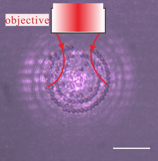
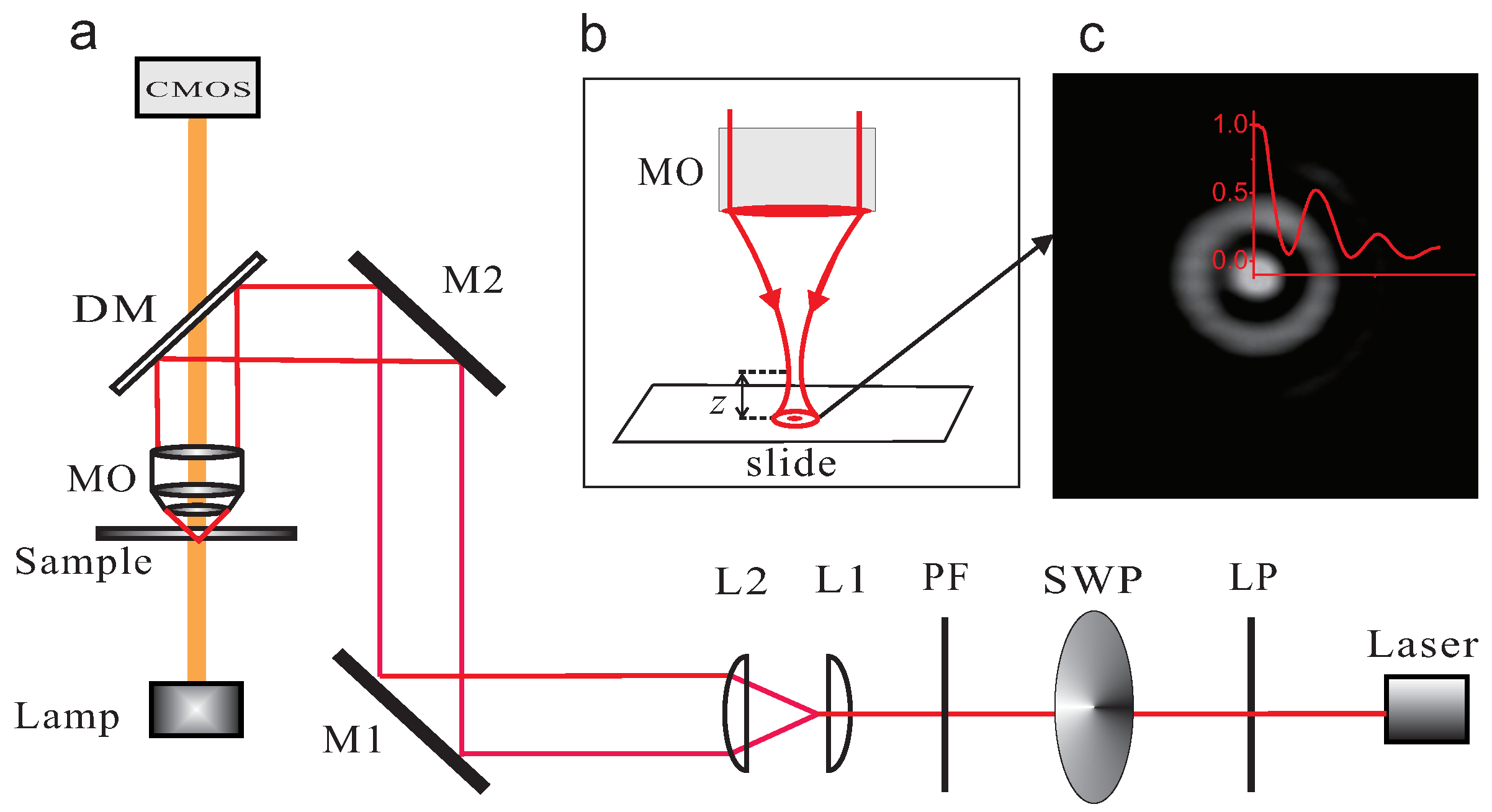
In typical optical tweezers, a high numerical aperture objective is used to focus a laser beam tightly for a three-dimensional potential well. In general, the aperture of the objective lens is much smaller than the waist of the trapping beam. The diameter of the objective aperture is 1 mm in the experiments. When the beams propagate through the objective lens, the diffraction patterns are visible at the slide–water interface. The bright diffraction fringes generate the diffraction optical traps near the surface of slide. 
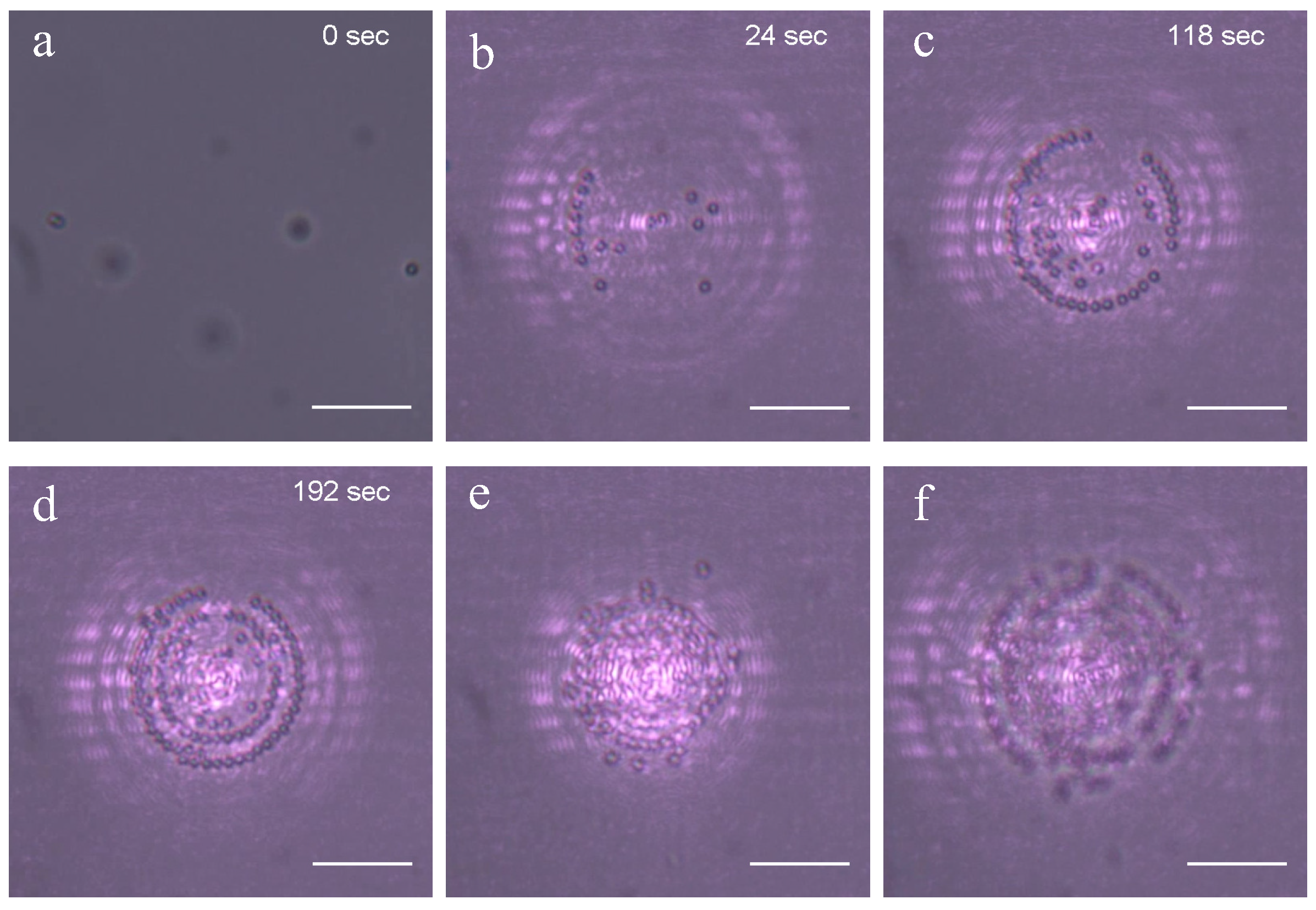
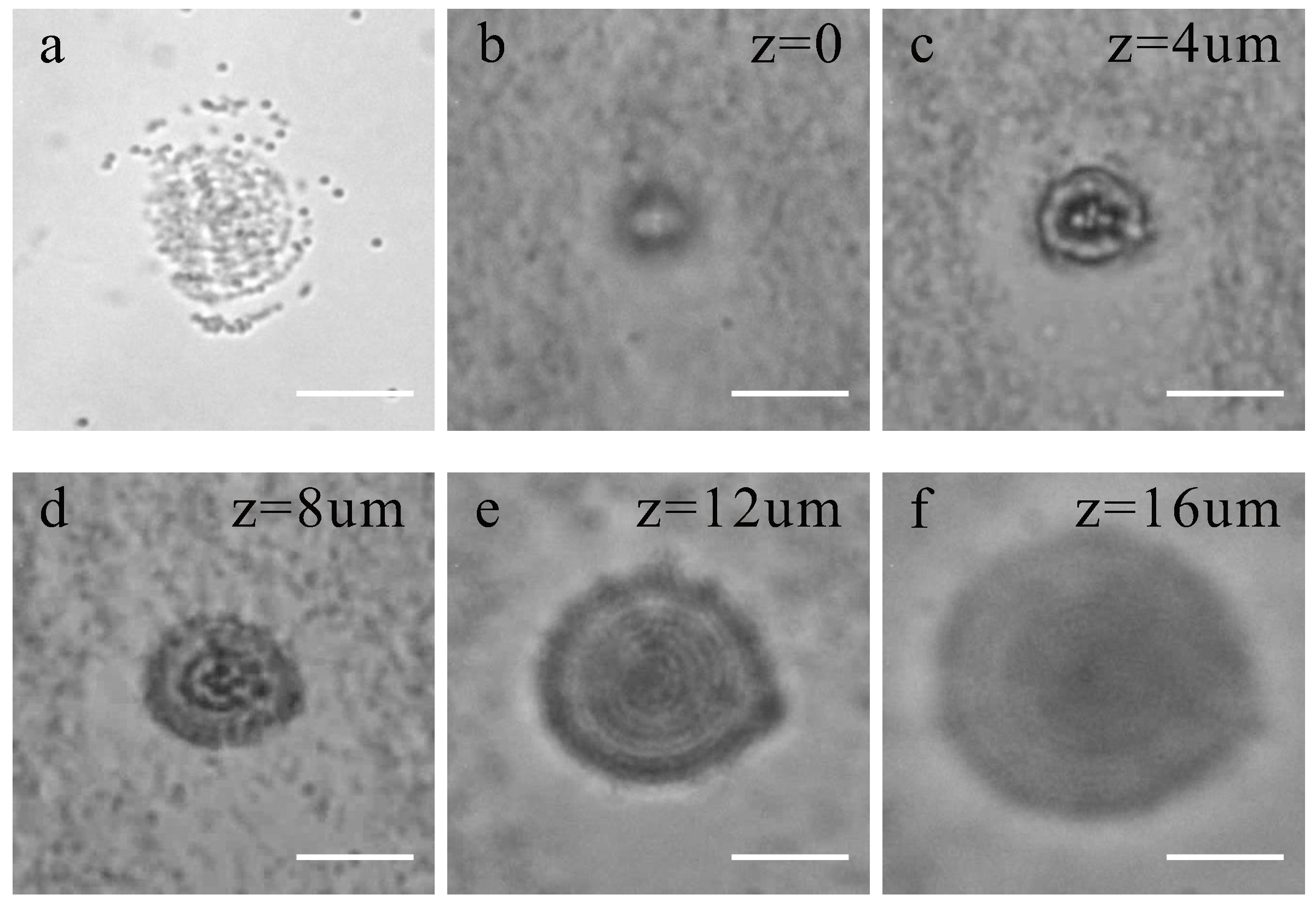
Figure 1c shows the diffraction pattern of the linearly polarized Gaussian beam and the corresponding light intensity distribution. Colloidal particles can be trapped by the bright diffraction fringes. The particles are trapped two-dimensionally at the slide surface, and the supporting force balances against the scattering force to prevent the particles from escaping from the traps. As the number of trapped particles increases, the particles form a ring structure at the glass–water interface. The process of rings’ structure formation is shown in Figure 2a–d. The laser power is 450 mW. The amount of 1 μ m particles in the solution is 2 × 10 8 cm 3 . At first, the micro-particles are dispersed and walk randomly before turning on the trapping laser, as shown in Figure 2a. When initiating the optical tweezers, the particles are attracted by the optical forces and confined in a bright region of diffraction fringes, as shown in Figure 2b. With time going on, the number of confined particles gradually increases, as shown in Figure 2b–d. Finally, particles are assembled into the structure of several concentric rings, under the control of optical forces from bright diffraction fringes. We also use a circularly polarized beam to repeat the assembling experiments. The result is similar to that of the linearly polarized beam, and the particles are confined in the bright region of diffraction fringes to form a concentric ring structure.
Most of the optical tweezers are three-dimensional optical traps, which can manipulate the particles axially (in a z-direction) by changing the trapping depth. However, the optical traps generated by the bright diffraction fringes in this paper are two-dimensional traps, and there is not enough axial gradient force to overcome the scattering force for manipulating the particles in the z-direction. Contrast to three-dimensional optical traps, changing the the distance between the focus and the glass surface can not manipulate the particles in the z-direction, but can move the particles transversely in the xy plane. By changing the the distance between the focus and the glass surface, the radii of the diffraction rings are changed at the slide surface. When the radii of the diffraction rings change, the radii of the particles rings are changed accordingly because the particles are driven by the diffraction rings in the xy plane. The changes of rings radii are showed in Figure 2d–f. In Figure 2d, the particles rings are initially at the trapping depth of 1 μ m. When the trapping depth decreases, the radii of diffraction rings become small. The radii of the particles rings decrease with the decreasing of the radii of diffraction rings. Figure 2e shows the image of the particles rings when the trapping depth decreases to ∼0.5 μ m. It can be seen that the radii of particles rings become smaller compared to Figure 2d, and the aggregation is more compact. When the trapping depth increases, the radii of the particle rings become larger, as shown in Figure 2f. Furthermore, the movement of the total ring structure at the interface can be achieved by shifting the diffraction pattern at the xy plane. When the trapping depth is larger than 3 μ m, the intensity of high order bright fringes and the optical forces decrease drastically at the slide–water interface. The diffraction optical traps become an ordinary three-dimensional optical trap, which can trap the particles only at the focus spot.
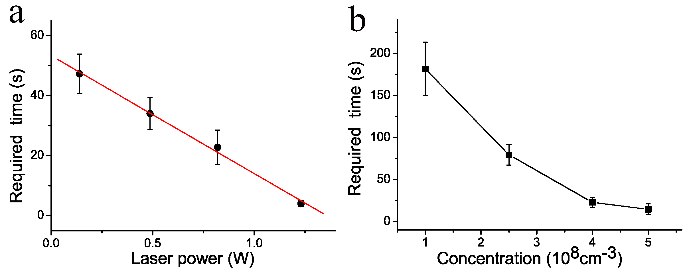
The confinement capabilities of the diffraction optical traps are related to the particle concentration and laser power. We evaluate the confinement capabilities of the diffraction optical traps by the time required for a complete pattern. The complete pattern means the outermost diffraction fringe has been full of particles. The required times are measured for various laser power and the different concentrations. Figure 3a shows the relation between the required time and laser power for 1 μ m particles at the number concentrations of 4 × 10 8 cm 3 . The required time decreases linearly with the laser power increasing because the optical gradient force is proportional to the laser power. Figure 3b shows the relation between the required time and particle concentration for a 1 μ m particle at the laser power of 820 mW. The required time decreases when the particle concentration increases. The larger particle concentration means that there are more particles around the diffraction fringes, so the bright fringes have more opportunities to trap the particles and shorter time is required to form a complete pattern.

3.2. Patterns Affected by Particle Size and Concentration

In the experiments, polystyrene microspheres with a diameter of 2 μ m, 1 μ m, 0.5 μ m, and 0.2 μ m are used for the optical trapping. As shown in Section 3.1, the 1 μ m particles form a ring structure. However, the 2 μ m particles assemble to form a close-packed structure in the experiments. When the trapping laser beam irradiates at the slide, and the distance between two bright diffraction fringes are related to the aperture of the microscope objective. The distance between two bright fringes is about 2 μ m at a trapping depth of 1 μ m. Therefore, the 1 μ m particles are confined at the bright fringes and the rings of particles can be distinguished individually. When the size of trapped particles becomes larger, each particle bestrides two bright fringes. Then, the particles form a compact structure, and no ring structure can be observed.
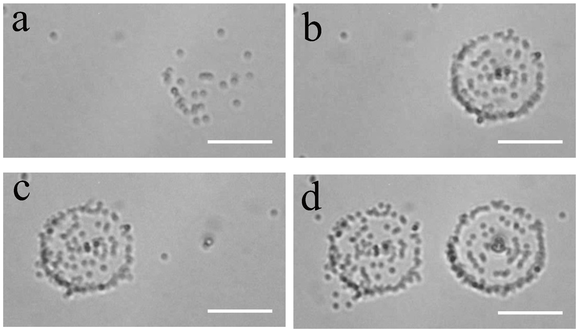
The 0.5 μ m particles can form a ring structure at a trapping depth of ∼0.5 μ m, as shown in Figure 4a. The laser power is 820 mW, and the particle concentration is 4 × 10 9 cm 3 . It is found that some particles is unstable. When the diameters of particles become smaller, the optical forces from the diffraction fringes acting on the particles decrease drastically. The gradient forces of some fringes are not enough to overcome the Brownian motion, so some particles randomly leave the diffraction fringes. It is beneficial to confine more particles stably in the rings at higher laser power. At this concentration, it is similar to the phenomenon of 1 μ m particle. The radii of particle rings can be changed by changing the trapping depth. When the trapping depth is larger than 3 μ m, there is no ring pattern formed.
The 0.2 μ m particles with a concentration of 4 × 10 9 cm 3 do not form a stable ring structure at the trapping depth of ∼0.5 μ m and even the laser power is added to 1.5 W. We believe that the gradient forces on the 0.2 μ m particles generated by the diffracted fringes have been overwhelmed by the thermal fluctuations; therefore, diffraction fringes can not confine the 0.2 μ m particles to form stable ring structures.
In this paper, we also do the experiments with 0.5 μ m and 0.2 μ m particles at large concentrations. It is found that the formed patterns are different from that at the low concentration. Even the diffraction fringes can not confine the particles stably, the 0.2 μ m particles can form the unstable ring structure at the trapping depth of 5 μ m when the concentration is added to 10 11 cm 3 . There are lots of particles attracted into the bright diffraction fringes. Since the concentration of particles is so high, there are many particles around the diffraction fringes. The number of particles entering and leaving the rings are equal, so the particles can form a clear ring structure under the action of very weak gradient forces.
Furthermore, even at the position where the trapping depth reaches 15 μ m, the ring structure formed by the 0.5 μ m particle is still clearly visible at the concentration of 10 11 cm 3 . At the concentration of 10 11 cm 3 , the 0.5 μ m particles rings are changed with trapping depth increasing, as shown in Figure 4b–f. When the laser beam is focused on the slide, the radius of the particles ring is small. As the trapping depth increases, the higher order diffraction fringes are able to gather the particles, which gradually increase the radii of particle rings. Lots of the particles form dynamic stable ring structures because the transverse gradient forces attract them into the diffraction fringes.
In the experiments, the radius of the 0.2 μ m particles ring is smaller than that of 0.5 μ m. At the laser power of 820 mW, the 0.5 μ m particles form the rings with a maximum radius of ∼6 μ m, while the 0.2 μ m particles form the rings with a maximum radius of ∼3 μ m at a trapping depth of 5 μ m. Because the light intensities are weak for the high order diffraction fringes, the gradient forces can not drive the 0.2 μ m particles to form rings and the maximum radius is smaller than that of 0.5 μ m particle rings.
However, the 1 μ m particles can not form a ring structure even if the concentration is as high as 2 × 10 10 cm 3 (original concentration) when the trapping depth is larger than 3 μ m. The gravity of the 1 μ m particle is large, and the particles can not stay in the position with a high trapping depth within a sufficient time. There are not enough particles to form an unstable ring structure at a high trapping depth. However, the gravity of a 0.5 μ m particle is much smaller, and the particles can stay in a position far away from the slide surface. Thus, the gradient force drives the 0.5 μ m particles into the bright fringes to form a ring structure at a high trapping depth.

3.3. Controlling the Particle Distribution with Cylindrical Vector Beams

The particle distribution in the transverse plane can be controlled by changing the properties of the focused beam, which can be obtained by changing the ratio of the waist of the laser beam to the objective aperture [23], or using structured beams as the optical trapping beam [24,25]. In this paper, we use the cylindrical vector beam to vary the intensity of the focused beam and study the optical assembling of the particles under the diffraction patterns. Cylindrical vector beams are the class of laser beams that arise from the solution to the vector Helmholtz equation with cylindrical boundary conditions. Cylindrical vector beams possess azimuthal symmetry in their amplitude distribution and a spatially inhomogeneous polarization direction [24]. There has been a rapid increase in investigations on cylindrical vector beams because of their interesting properties and potential applications in optical trapping and laser machining [26,27,28,29]. In this paper, the linearly polarized beam becomes a cylindrical vector beam after passing through the s-waveplate. The polarization angle, ψ , is varied by rotating the s-waveplate. Beams with ψ = 0 and ψ = π /2 are radially and azimuthally polarized, respectively. The transmission of the s-waveplate for radially and azimuthally polarized beams at 1064 nm are 77.6% and 68.3%, respectively. The laser power before the objective lens are 450 mW for the two cylindrical vector beams in the experiments.
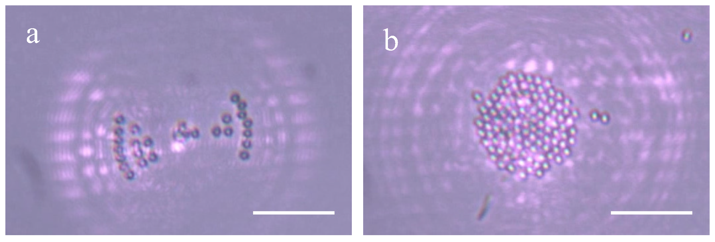
There is a dark line in the center of the diffraction patterns of the azimuthally polarized beam, which is consistent with the previous investigation [30]. After passing through the polarization filter in Figure 1a, the shape of intensity of the azimuthally polarized beam becomes a two-fan shape. There are two bright spots in the center, which are separated by a black line. The diffraction pattern is divided into two parts as fan-shaped distribution. When the trapping laser is working, the particles are also attracted and confined in the bright fringes. As the number of trapped particles increases, the particles are arranged as two fan-shaped distribution, as shown in Figure 5a, due to the fan-shaped distribution of the diffraction patterns. Although the center of the diffraction patterns is a dark line, the particles are attracted to the center of the fans because of the existence of two bright spots in the central region. The central dark line is covered by the particles and can not be observed in the particle patterns. The fan-shaped formation can be rotated by rotating the polarization direction of the polarization filter.
We repeated the assembling experiment with a radially polarized beam. In the experiments, the radially polarized beam is no longer passing through the polarization filter in Figure 1a. When the trapping laser starts to work, the particles can be trapped and confined by the bright diffraction fringes. However, as time goes on, most of the particles are gradually attracted into the central diffraction spot. The trapped particles in the center gradually form a compact structure, and the result is shown in Figure 5b.
The intensity distributions of the diffraction fringes are measured in the experiment when the trapping depth is 1 μ m from the interface. The results are listed in Table 1. The main peak in Table 1 is the brightest fringe of the central diffraction spot. For the linearly polarized beam, the main peak is the intensity of the bright central spot. There is a dark annulus in the intensity distributions of the diffraction field of the azimuthally and radially polarized beam. In the Table 1, we take the brightest fringes close to the dark annulus as the main peaks. The peak intensities are normalized by the intensity of the main peak, respectively. The light intensity of focused radially polarized beam is more concentrated in the main diffraction spot, as seen in Table 1. Furthermore, the radially polarized beam can be focused to a spot size significantly smaller than for linearly polarized beam [30]. The spot with a smaller size and stronger intensity will generate a stronger gradient force for the radially polarized beam. The gradient force generated by the central spot drives most of the particles into the center, which changes the whole diffraction pattern. The intensities of the high-order diffraction fringes are weak, and only the central spot can trap the particles. Finally, the particles are assembled to a compact structure, as shown in Figure 5b. It can be seen that the size of the two-dimensional particles aggregation is much larger than the size of the central spot, but the particles still form a stable structure.
For optical tweezers in the water, the particles far from the trap center can be attracted by the forces from the high order fringes. The attracted particles move towards the trap center and are finally trapped at the central spot. This is why optical tweezers can trap the particles far from the trap center. Furthermore, only the central spot has sufficient axial gradient force, and the other diffraction fringes do not have sufficient axial force to confine the particles in the water, so the fringes can not form stable three-dimensional traps, and the particles can only be trapped by the central spot in the water.

3.4. Forming Steady Patterns of Particles in a Salt Solution

The particles form a ring structure in deionized water because they are confined by the gradient forces generated by the diffraction spot. It is the same as the previous studies, and the particles are trapped against the surface and can not escape from the traps [15,21,25]. However, the aggregation is unstable without the laser confinement. When the laser is off, the particles are free to move and the formed patterns of particles will be destroyed.
Forming steady patterns of micro-particles is of great interest. The interaction between the dispersed particles can be described with Derjaguin-Landau-Verwey-Overbeek (DLVO) theory. Our above experiments are carried out in deionized water, and the particle structures are destroyed when the laser is off. In order to form steady patterns of micro-particles, there must be chemical conditions such that the particles have strong interactions. If the particles are in a salt solution, the ionic concentration will change the interaction of the particles, and eventually change the particle structures [31,32,33]. Previous research has demonstrated that the interaction of the particles can be adjusted by using different concentrations of NaCl in polystyrene solution, and found that 0.5 mol/L NaCl is very appropriate for forming steady patterns [34]. Under this NaCl concentration, the particles are mostly single and do not gather quickly, which makes pattern formation easy.
In the experiment, the 0.5 μ m particles are washed and dispersed in 0.5 mol/L NaCl solution. The particle concentration is 4×10 9 cm 3 . In the experiment, the particles are attracted into the diffraction traps at a trapping depth of ∼0.5 μ m. When the particles are attracted into the diffraction rings, the particles do not walk randomly but adhere to the slide surface firmly. The ring pattern is steady, and the structure is clear in view. The steady pattern formed by the diffraction traps remains even when the laser is off. This method can be used to print the particle patterns on the surface of the slide. The process of duplication is shown in Figure 6. When a particle pattern is completed, then the pattern is moved to the left by the sample stage. After 50 s, the particles form a new particle pattern by the diffraction fringes.
The method for assembling particles in this paper is limited with the particle size. According to experiment results, the method can not assemble the particles with a diameter larger than 2 μ m into a ring structure because the large particles are closely assembled. Furthermore, this method also fails to assemble the particles with a diameter smaller than 500 nm into a ring structure. When the particle diameter becomes smaller, the gradient forces generated by the diffraction fringes are insufficient to overcome the Brownian motion.
The diffraction traps demonstrated in the paper can only assemble transparent colloidal particles but can not be used to assemble metal particles and absorbing particles. For metal particles, the forces exerted by the diffraction fringes repel them to leave the traps. For the absorbing particles, the laser heating of particles results in a strong thermal gradient that drives the particles to leave the diffraction fringes [35,36,37]. Plasmonic tweezers may be a suitable method to assemble the metal or absorbing particles [38,39,40,41].
The size of the ring structure formed by particle assembly is limited. The action range of the diffraction fringes are limited, so the particles can only be assembled within the action range and it is difficult to assemble the particles in a large scale. If more ring structures are to be assembled, it is necessary to add a salt solution to adjust the interaction between the particles and the slide; then, the particles can be assembled and fixed on the slide. By moving the sample cell with the help of sample stage, a lot of particles’ ring structures can be duplicated and printed.

3.5. Disadvantage of the Diffraction Trap in the Application of Optical Tweezers

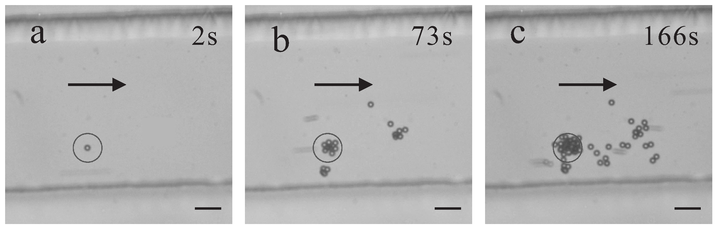
When the optical tweezers are close to the interface, the diffraction may seriously disturb some experiment processes, such as application in the micro-channel. The particles may be seriously gathered by optical tweezers at the bottom surface of the micro-channel. In our experiment, the 2 μ m particle suspension is injected into the micro-channel. The velocities of the particles are measured by tracking the particles’ motion in the images. The particles are flowing with the velocity of 715 ± 157 μ m/s in the micro-channel. The particles’ concentration is 2.5 × 10 8 cm 3 and the laser power is 1.5 W. As shown in Figure 7a, the optical tweezers can only trap a single particle, and there is no aggregation in the micro-channel at the beginning. However, more particles are trapped by the diffraction traps, and more and more aggregation of particles settles in the lower part of the flow close to the trap. On the other half side of the micro-channel, the particles do not aggregate due to the absence of the optical tweezers. The experiment shows that the diffraction will seriously affect the flowing of particles in the micro-channel.
The particles aggregate at the surface of the micro-channel, which can be due to the ability of trapping a large number of particles by the diffraction traps. After the traps confine a lot of particles and form the aggregation, the flow velocity downstream of the aggregation becomes slow, which will induce more particles into further aggregation.
The aggregation is mainly related to the change of particle flowing. If one solvent with lower viscosity is used to dilute the particles, the flowing ability of particles in the micro-channel can be improved, which may be helpful to reduce the aggregation in the micro-channel. If the particles are diluted by the solvents, which can weaken the particle interaction, we think it might not be effective for reducing the aggregation. On the other hand, if the solvent strengthens the particles interaction, it will lead to more aggregation.
In addition, when optical tweezers are usually used to measure the tiny forces near an interface, the diffraction of trapping beam may seriously interfere with the correct experiment result if the optical trap is close to the surface. Besides the hydrodynamic correction [42,43], the optical trapping by the diffraction fringes should be avoided. In the experiments, we found that using the total reflect mirror as the bottom surface of sample cell can prevent the optical tweezers from forming diffraction traps for collecting a large amount of particles. The axial forces on the particles from the high order diffraction fringes are equal to axial forces of the total reflection beam, so the traps generated from the high order fringes are unstable traps, and the particles leave the fringes due to the Brownian motion. The optical trapping becomes similar to the optical trapping in water, and the particles can only be trapped on the central spot.

4. Conclusions

In summary, we have proposed and demonstrated utilization of diffraction of a trapping laser beam for the optically guided assembly of colloidal particles at the glass–water interface. The trapping laser beams include linearly, azimuthally and radially polarized beams. The diffraction optical traps assemble the particles to form ring structures for linearly polarized beams. The results show that the particle distributions in the transverse plane are drastically affected by the particle size and concentration. With the help of a polarizer, the particles are arranged as fan-shape structures with azimuthally polarized beams. The particles are accumulated and crystallized as a two-dimensional compact structure under the optical force generated by the radially polarized beam.
NaCl, serving as the electrolyte, is used to change the particle–particle interaction, and the interaction between the particles and substrate slide. Under the concentration of NaCl at 0.5 mol/L, the particle patterns are easily printed steadily on the glass surface. The ability of trapping and manipulating an amount of particles has been expected to provide an intersecting method for self-organization assembly [44,45,46]. Furthermore, we discuss the influence on the application of optical tweezers in microfluidic channels, and use a reflector as the surface of the sample cell to avoid the diffraction traps’ induced aggregation. The demonstrated examples in this paper might have applications for two-dimensional colloidal assembly and understanding the principle of optical tweezers.

Author Contributions

M.-C.Z. conceived and designed the research. M.-C.Z., A.-Y.L. and R.Z. performed the experiments. M.-C.Z. and R.Z. processed images and analyzed the experiment data. M.-C.Z. wrote the manuscript. All of the authors revised the manuscript.

Funding

This work is supported by the National Natural Science Foundation of China (Nos. 11302220 and 11874138), and the Fundamental Research Funds for the Central Universities (No. PA2017GDQT0024).

Acknowledgments

The manuscript has been greatly improved by addressing the constructive comments and suggestions made by two anonymous reviewers, whom we would like to thank for their time and efforts.

Conflicts of Interest

The authors declare no conflict of interest.

References

  1. Zhang, T.H.; Liu, X.Y. Effect of Long-Range Attraction on Growth Model. J. Phys. Chem. C 2007, 111, 1342–1346. [Google Scholar] [CrossRef]
  2. Jiang, H.R.; Wada, H.; Yoshinaga, N.; Sano, M. Manipulation of Colloids by a Nonequilibrium Depletion Force in a Temperature Gradient. Phys. Rev. Lett. 2009, 102, 208301. [Google Scholar] [CrossRef] [PubMed]
  3. Coleman, J.N.; Lotya, M.; O’Neill, A.; Bergin, S.D.; King, P.J.; Khan, U.; Young, K.; Gaucher, A.; De, S.; Smith, R.J. Two-Dimensional Nanosheets Produced by Liquid Exfoliation of Layered Materials. Science 2011, 42, 568–571. [Google Scholar] [CrossRef] [PubMed]
  4. Ashkin, A.; Dziedzic, J.M.; Bjorkholm, J.E.; Chu, S. Observation of a single-beam gradient force optical trap for dielectric particles. Opt. Lett. 1986, 11, 288–290. [Google Scholar] [CrossRef] [PubMed]
  5. Zhou, J.H.; Qu, L.J.; Yao, K.; Zhong, M.C.; Li, Y.M. Observing nanometre scale particles with light scattering for manipulation using optical tweezers. Chin. Phys. Lett. 2008, 25, 329–331. [Google Scholar]
  6. Li, Y.C.; Xin, H.B.; Lei, H.X.; Liu, L.L.; Li, Y.Z.; Zhang, Y.; Li, B.J. Manipulation and detection of single nanoparticles and biomolecules by a photonic nanojet. Light Sci. Appl. 2016, 5, e16176. [Google Scholar] [CrossRef]
  7. Lee, K.; Shirshin, E.; Rovnyagina, N.; Yaya, F.; Boujja, Z.; Priezzhev, A.; Wagner, C. Dextran adsorption onto red blood cells revisited: single cell quantification by laser tweezers combined with microfluidics. Biomed. Opt. Express 2018, 9, 2755–2764. [Google Scholar] [CrossRef]
  8. Kampmann, R.; Sinzinger, S.; Korvink, J.G. Optical tweezers for trapping in a microfluidic environment. Appl. Opt. 2018, 57, 5733–5742. [Google Scholar] [CrossRef] [PubMed]
  9. Crocker, J.C.; Grier, D.G. Microscopic Measurement of the Pair Interaction Potential of Charge-Stabilized Colloid. Phys. Rev. Lett. 1994, 73, 352–355. [Google Scholar] [CrossRef] [PubMed]
  10. Moffitt, J.R.; Chemla, Y.R.; Izhaky, D.; Bustamante, C. Differential detection of dual traps improves the spatial resolution of optical tweezers. Proc. Natl Acad. Sci. USA 2006, 103, 9006–9011. [Google Scholar] [CrossRef] [PubMed] [Green Version]
  11. Pantina, J.P.; Furst, E.M. Directed assembly and rupture mechanics of colloidal aggregates. Langmuir 2004, 20, 3940–3946. [Google Scholar] [CrossRef] [PubMed]
  12. Curtis, J.E.; Koss, B.A.; Grier, D.G. Dynamic holographic optical tweezers. Opt. Commun. 2002, 207, 169–175. [Google Scholar] [CrossRef]
  13. Curtis, J.E.; Grier, D.G. Structure of Optical Vortices. Phys. Rev. Lett. 2003, 90, 133901. [Google Scholar] [CrossRef] [PubMed]
  14. Grier, D.G.; Roichman, Y. Holographic optical trapping. Appl. Opt. 2006, 45, 880–887. [Google Scholar] [CrossRef] [PubMed]
  15. Nedev, S.; Urban, A.S.; Lutich, A.A.; Feldmann, J. Optical Force Stamping Lithography. Nano Lett. 2011, 11, 5066–5070. [Google Scholar] [CrossRef] [PubMed] [Green Version]
  16. Tanaka, S.; Oki, Y.; Kimura, Y. Melting of a finite-sized two-dimensional colloidal crystal. Phys. Rev. E 2014, 89, 052305. [Google Scholar] [CrossRef] [PubMed]
  17. Zhong, M.C.; Wang, Z.Q.; Li, Y.M. Laser-accelerated self-assembly of colloidal particles at the water-air interface. Chin. Opt. Lett. 2017, 15, 051401. [Google Scholar] [CrossRef]
  18. Hiroaki, M.; Masanori, K.; Keiji, S.; Noboru, K.; Hiroshi, M. Spatial Pattern Formation, Size Selection, and Directional Flow of Polymer Latex Particles by Laser Trapping Technique. Chem. Lett. 1991, 20, 469–472. [Google Scholar]
  19. Haldar, A.; Pal, S.; Roy, B.; Gupta, S.; Banerjee, A. Self assembly of microparticles in stable ring structures in an optical trap. Phys. Rev. A 2012, 85, 033832. [Google Scholar] [CrossRef]
  20. Wang, S.F.; Yuyama, K.i.; Sugiyama, T.; Masuhara, H. Reflection Microspectroscopic Study of Laser Trapping Assembling of Polystyrene Nanoparticles at Air/Solution Interface. J. Phys. Chem. C 2015, 120, 15578–15585. [Google Scholar] [CrossRef]
  21. Kudo, T.; Wang, S.F.; Yuyama, K.; Masuhara, H. Optical Trapping-Formed Colloidal Assembly with Horns Extended to the Outside of a Focus through Light Propagation. Nano Lett. 2016, 16, 3058–3062. [Google Scholar] [CrossRef] [PubMed]
  22. Liu, J.; Li, Z.Y. Light-driven crystallization of polystyrene micro-spheres. Photonics Res. 2017, 5, 201–206. [Google Scholar] [CrossRef]
  23. Tan, R. Propagation of the Guassian beam through an aperture. Laser J. 2003, 24, 7–8. (In Chinese) [Google Scholar]
  24. Zhan, Q. Cylindrical vector beams: from mathematical concepts to applications. Adv. Opt. Photon 2009, 1, 1–57. [Google Scholar] [CrossRef]
  25. Donato, M.G.; Messina, E.; Foti, A.; Smart, T.J.; Jones, P.H.; Iatì, M.A.; Saija, R.; Gucciardi, P.G.; Maragò, O.M. Optical trapping and optical force positioning of two-dimensional materials. Nanoscale 2018, 10, 1245–1255. [Google Scholar] [CrossRef] [PubMed]
  26. Zhan, Q. Trapping metallic Rayleigh particles with radial polarization. Opt. Express 2004, 12, 3377–3382. [Google Scholar] [CrossRef] [PubMed]
  27. Meier, M.; Romano, V.; Feurer, T. Material processing with pulsed radially and azimuthally polarized laser radiation. Appl. Phys. A 2007, 86, 329–334. [Google Scholar] [CrossRef]
  28. Huang, L.; Guo, H.; Li, J.; Ling, L.; Feng, B.; Li, Z.Y. Optical trapping of gold nanoparticles by cylindrical vector beam. Opt. Lett. 2012, 37, 1694–1696. [Google Scholar] [CrossRef] [PubMed]
  29. Zhong, M.C.; Gong, L.; Li, D.; Zhou, J.H.; Wang, Z.Q.; Li, Y.M. Optical trapping of core-shell magnetic microparticles by cylindrical vector beams. Appl. Phys. Lett. 2014, 105, 181112. [Google Scholar]
  30. Dorn, R.; Quabis, S.; Leuchs, G. Sharper Focus for a Radially Polarized Light Beam. Phys. Rev. Lett. 2003, 91, 233901. [Google Scholar] [CrossRef] [PubMed]
  31. Sun, Z.; Xu, S.; Dai, G.; Li, Y.; Lou, L.; Liu, Q.; Zhu, R. A microscopic approach to studying colloidal stability. J. Chem. Phys. 2003, 119, 2399–2405. [Google Scholar] [CrossRef]
  32. Xu, S.H.; Lou, L.R.; Li, Y.M.; Sun, Z.W. On the aggregation kinetics of two particles trapped in an optical tweezers. Coll. Surf. A 2005, 255, 159–163. [Google Scholar] [CrossRef]
  33. Mellor, C.D.; Bain, C.D. Array Formation in Evanescent Waves. ChemPhysChem 2006, 7, 329–332. [Google Scholar] [CrossRef] [PubMed]
  34. Xu, S.H.; Li, Y.M.; Lou, L.R.; Chen, H.T.; Sun, Z.W. Steady patterns of microparticles formed by optical tweezers. Jpn. J. Appl. Phys. 2002, 41, 166–168. [Google Scholar] [CrossRef]
  35. Spesyvtseva, S.E.S.; Dholakia, K. Trapping in a Material World. ACS Photonics 2016, 3, 719–736. [Google Scholar] [CrossRef] [Green Version]
  36. Zhong, M.C.; Wang, Z.Q.; Li, Y.M. Oscillations of absorbing particles at the water-air interface induced by laser tweezers. Opt. Express 2017, 25, 2481–2488. [Google Scholar] [CrossRef] [PubMed]
  37. Mitra, T.; Brown, A.K.; Bernot, D.M.; Defrances, S.; Talghader, J.J. Laser acceleration of absorbing particles. Opt. Express 2018, 26, 6639–6652. [Google Scholar] [CrossRef] [PubMed]
  38. Volpe, G.; Quidant, R.; Badenes, G.; Petrov, D. Surface Plasmon Radiation Forces. Phys. Rev. Lett. 2006, 96, 238101. [Google Scholar] [CrossRef] [PubMed]
  39. Quidant, R.; Girard, C. Surface-plasmon-based optical manipulation. Laser Photonics Rev. 2008, 2, 47–57. [Google Scholar] [CrossRef]
  40. Min, C.; Shen, Z.; Shen, J.; Zhang, Y.; Fang, H.; Yuan, G.; Du, L.; Zhu, S.; Lei, T.; Yuan, X. Focused plasmonic trapping of metallic particles. Nat. Commun. 2013, 4, 2891. [Google Scholar] [CrossRef] [PubMed]
  41. Zhang, Y.; Dou, X.; Dai, Y.; Wang, X.; Min, C.; Yuan, X. All-optical manipulation of micrometer-sized metallic particles. Photonics Res. 2018, 6, 66–71. [Google Scholar] [CrossRef]
  42. Vermeulen, K.C.; Wuite, G.J.L.; Stienen, G.J.M.; Schmidt, C.F. Optical trap stiffness in the presence and absence of spherical aberrations. Appl. Opt. 2006, 45, 1812–1819. [Google Scholar] [CrossRef] [PubMed]
  43. Wang, G.M.; Prabhakar, R.; Sevick, E.M. Hydrodynamic Mobility of an Optically Trapped Colloidal Particle near Fluid-Fluid Interfaces. Phys. Rev. Lett. 2009, 103, 248303. [Google Scholar] [CrossRef] [PubMed]
  44. Burns, M.M.; Fournier, J.M.; Golovchenko, J.A. Optical matter: crystallization and binding in intense optical fields. Science 1990, 249, 749–754. [Google Scholar] [CrossRef] [PubMed]
  45. Woerdemann, M.; Alpmann, C.; Denz, C. Optical assembly of microparticles into highly ordered structures using Ince–Gaussian beams. Appl. Phys. Lett. 2011, 98, 111101. [Google Scholar] [CrossRef]
  46. Gould, O.E.; Qiu, H.; Lunn, D.J.; Rowden, J.; Harniman, R.L.; Hudson, Z.M.; Winnik, M.A.; Miles, M.J.; Manners, I. Transformation and patterning of supermicelles using dynamic holographic assembly. Nat. Commun. 2015, 6, 10009. [Google Scholar] [CrossRef] [PubMed] [Green Version]
Figure 1. (a) optical tweezers setup. Instrument layout showing optical paths for 1064 nm trapping laser and lamp for bright imaging. L1–L2, lens; M1–M2, mirrors; MO, microscope objective; DM, dichroic mirror; SWP, s-waveplate; LP, linear polarizer; PF, polarization filter; (b) schematic illustration of the focal region produced inside the sample cell. z is the trapping depth; (c) diffraction pattern and light intensity distribution (a.u.) on the slide.
Applsci 08 01522 g001
Figure 2. Images of the assembly formed by the diffraction pattern. (a) before the laser working; (bd) generation of particles ring structure at the interface; (e,f) the radius of rings varied. The laser beam is irradiated perpendicularly to the imaging plane, and the power is 450 mW. The number concentration of 1 μ m particles in the solution is 2 × 10 8 cm 3 ; scale bar, 10 μ m.
Applsci 08 01522 g002
Figure 3. Confinement capabilities of diffraction traps for 1 μ m particles. (a) the confinement capability as a function of laser power at a particle concentration of 4 × 10 8 cm 3 ; (b) the confinement capability as a function of particle concentration at laser power 820 mW.
Applsci 08 01522 g003
Figure 4. Images of the 0.5 μ m particles assembly formed by the diffraction pattern. (a) particle patterns at low concentration (4 × 10 9 cm 3 ); (bf) particle patterns at high concentration (10 11 cm 3 ). The power is 820 mW; scale bar, 10 μ m.
Applsci 08 01522 g004
Figure 5. Images of the 1 μ m particles assembly formed by the diffraction patterns of the cylindrical vector beams. (a) azimuthally polarized beam. The particles form a two-fan-shaped structure at the interface; (b) radially polarized beam. Most of the particles are driven into the center and form a compact structure at the interface. The amount of 1 μ m particles in the solution is 2 × 10 8 cm 3 . Laser power is 450 mW; scale bar, 10 μ m.
Applsci 08 01522 g005
Figure 6. Images of forming two particle patterns by the diffraction pattern. (a,b) forming process of the first pattern. (c,d) forming process of the second pattern. The first pattern has been moved to the left. The 0.5 μ m particles’ concentration is 4 × 10 9 cm 3 . The laser power is 820 mW; scale bar, 10 μ m.
Applsci 08 01522 g006
Figure 7. Optical trapping of a number of particles leads to aggregation in the micro-channel. (a) initially, optical tweezers trap one particle and flows quickly through the micro-channel; (b,c) more particles are trapped by the diffraction fringes, and more and more particles are settled in the micro-channel. The laser power is 1.5 W; scale bar, 10 μ m; the circles indicate the optical trap and the arrows indicate the flow direction.
Applsci 08 01522 g007
Table 1. Intensity of the diffraction peaks.
PolarizationMain Peak1st Peak2nd Peak
Linear10.540.31
Radial10.330.12
Azimuthal10.930.84

