Article

Prototype Design and Performance Tests of Beijing Astronaut Robot

1
School of Mechatronical Engineering, Beijing Institute of Technology, Beijing 100081, China
2
Beijing Advanced Innovation Center for Intelligent Robots and Systems, Beijing 100081, China
3
Key Laboratory of Biomimetic Robots and Systems, Ministry of Education, Beijing 100081, China
4
LARM: Laboratory of Robotics and Mechatronics, DICeM, University of Cassino and South Latium, Via Di Biasio 43, 03043 Cassino FR, Italy
*
Author to whom correspondence should be addressed.
Appl. Sci. 2018, 8(8), 1342; https://doi.org/10.3390/app8081342
Submission received: 2 July 2018 / Revised: 6 August 2018 / Accepted: 6 August 2018 / Published: 10 August 2018
(This article belongs to the Special Issue Advanced Mobile Robotics)

Abstract

:

Featured Application

A novel chameleon-like astronaut robot that is designed to assist, or even substitute, an astronaut in a space station to complete dangerous and prolonged work.

Abstract

This paper proposes a novel chameleon-like astronaut robot that is designed to assist, or even substitute, a human astronauts in a space station to complete dangerous and prolonged work, such as maintenance of solar panels, and so on. The robot can move outside the space station freely via the hundreds of aluminum handrails, which are provided to help astronauts move. The robot weighs 30 kilograms, and consists of a torso, three identical 4-degree of freedom (DOF) arms, three end effectors, and three monocular vision system on each end effector. Via multi-arm associated motion, the robot can realize three kinds of motion modes: walking, rolling, and sliding. Numerous experiments have been conducted in a simulation environment and a ground verification platform. Experimental results reveal that this robot has excellent motion performance.

1. Introduction

With the development of space technology, a space station is a vital approach for human beings to study and research space, but its construction and maintenance require extravehicular activity (EVA) carried out by astronauts [1]. Since the space environment has the characteristics of high vacuum, large temperature differences, high radiation, and microgravity, which result in the failure of continuous working time and inefficiency, humans in space require a large and a complex life support system, an environmental control system, and life-saving system, and requires a lot of uninterrupted material supply [2]. Under such conditions, space operations of astronauts are not only dangerous but also costly. Therefore robots are used as assistants or replacements more and more frequently to reduce the risk and cost. In addition, space robots do better in load capacity, accurate positioning, adaption to environments, and durable work. Space robots can install precise devices, maintain the space station, and perform experiments in space without health concerns [3].
So far, a few robotic arms have been applied in the International Space Station which is being assembled in low Earth orbit, for example Canadarm2 [4] and Robonaut [5]. Canadarm2 was designed by the Canadian Space Agency and it is used mainly for payload handling, EVA support, and the international space station’s assembly [6]. The Special Purpose Dexterous Manipulator (SPDM) is the third Canadian robotic arm used on the International Space Station (ISS), preceded by the Space Shuttle's Canadarm and the large Canadarm2 [7]. It is an extremely advanced, highly dexterous, dual-armed robot which can carry out delicate maintenance and servicing tasks on the ISS. Robonaut is a humanoid robot designed by the Robotic Systems Technology Branch at NASA’s Johnson Space Center. Robonaut can reduce the burden of EVA on astronauts and also serve in rapid response capacities.
Canadarm2 and Robonaut are all well designed, but they can be considered as too complicated, and are designed only for specific activities, so they cannot work in all of the places outside the space station. There are many operational tasks in space, so the robot needs the ability of moving in a wide range and the ability of precise work. Moreover, the power supply on the space station is limited, so the path planning of the space robot should be power-saving [8,9].
Astronauts are weightless and floating in space. Thus, there are hundreds of aluminum handrails and poles on the extravehicular surface of the space station (as shown in Figure 1) for astronauts to get themselves to the expected position during spacewalks and operations. Most importantly, astronauts are fixed by these handrails so that they will not float away.
A chameleon is a kind of arboreal reptile with a simple physical structure, but can move stably [10]. The conditions of the extravehicular surface are kind of similar to the structure of tree crown. Thus, referring to the simple physical structure and stable motion pattern, a new pattern of a hybrid bionic robot, called the Beijing Astronaut Robot, prototype is design is developed and performance tests are presented in this paper.

2. The Mechanical Structure and Test System Design of the Robot

2.1. Design Indicators

It is very difficult to transport large volume or heavy weight objects from the ground to a space station. The design of the space robot needs to meet the requirements of the operations on the space station and, at the same time, the mass and the volume should be as small as possible [11]. Parameters and functional indicators of the Beijing Astronaut Robot are as follows:
  • The total mass of the robot is less than 30 kg;
  • The total degrees of freedom (DOF) of the robot is no less than 12;
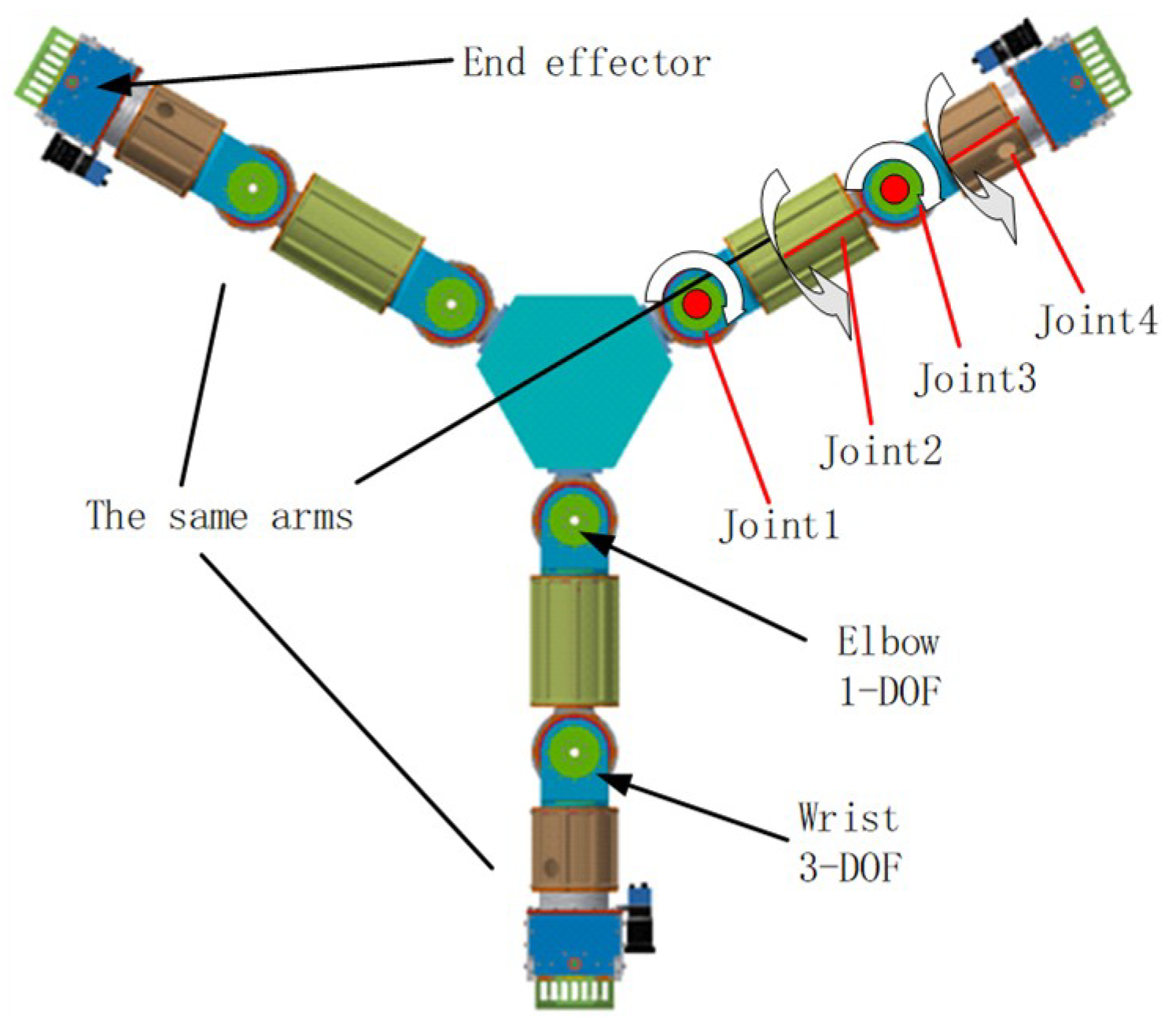
  • The robot has at least three arms, each arm has no less than 4-DOF;
  • The robot arm length is not more than 700 mm.
According to the structural environment outside the space station and the characteristics of the robot itself, the robot has three kinds of motion modes: walking, rolling and sliding. The motion index in each motion mode is as follows:
  • Walking mode, the stride of the robot is not less than 30 cm, the robot movement speed is not less than 0.1 m/s;
  • Rolling mode, the robot's stride is not less than 60 cm, the robot movement speed of not less than 0.2 m/s; and
  • Sliding mode, the moving speed of the robot is not less than 0.5 m/s.
When the robot performs the motion and operation tasks outside the space station, the robot’s visual measurement, end positioning and force control are supposed to have high precision. The specific indicators are as follows:
  • Visual measurement accuracy not less than 1 mm in the range of 200 mm;
  • End effector’s positioning accuracy within 2 mm;
  • End effector’s force control accuracy within 2 N.

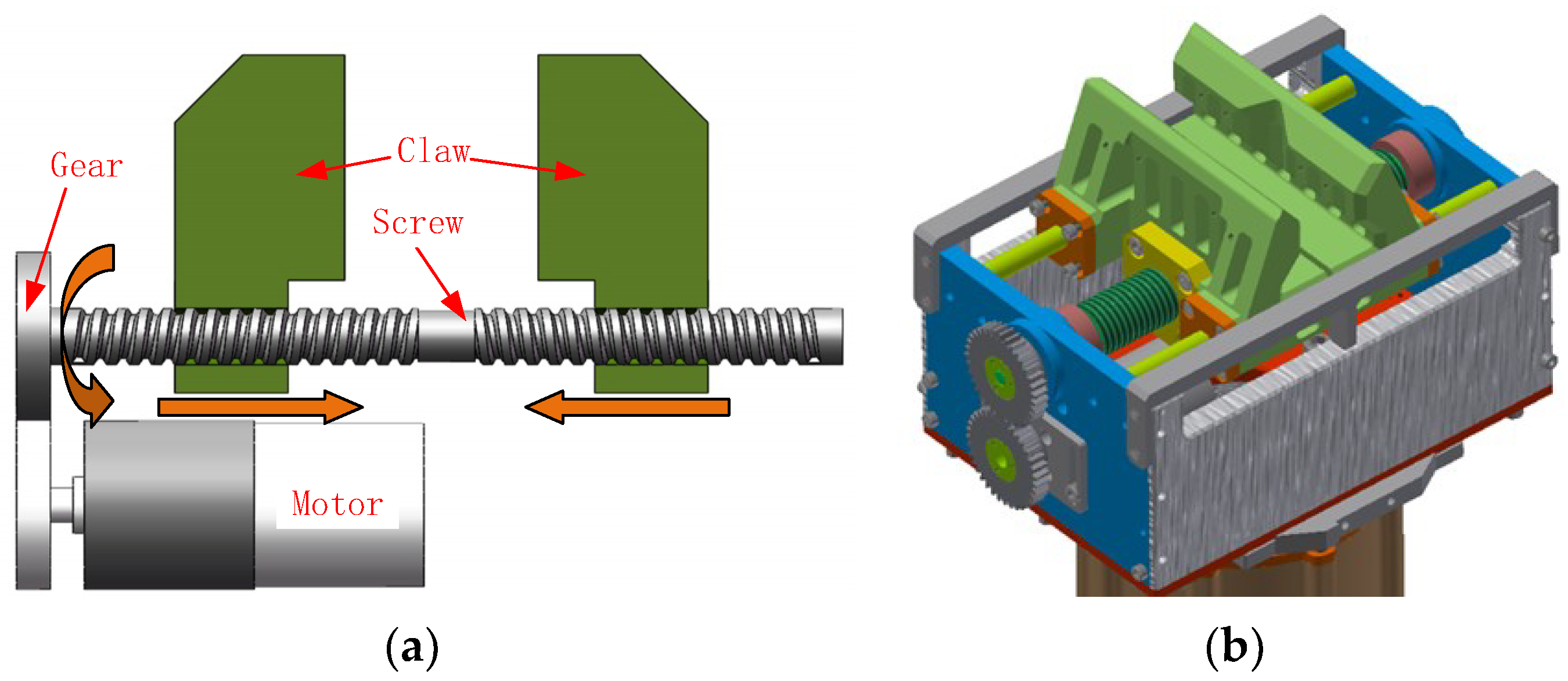
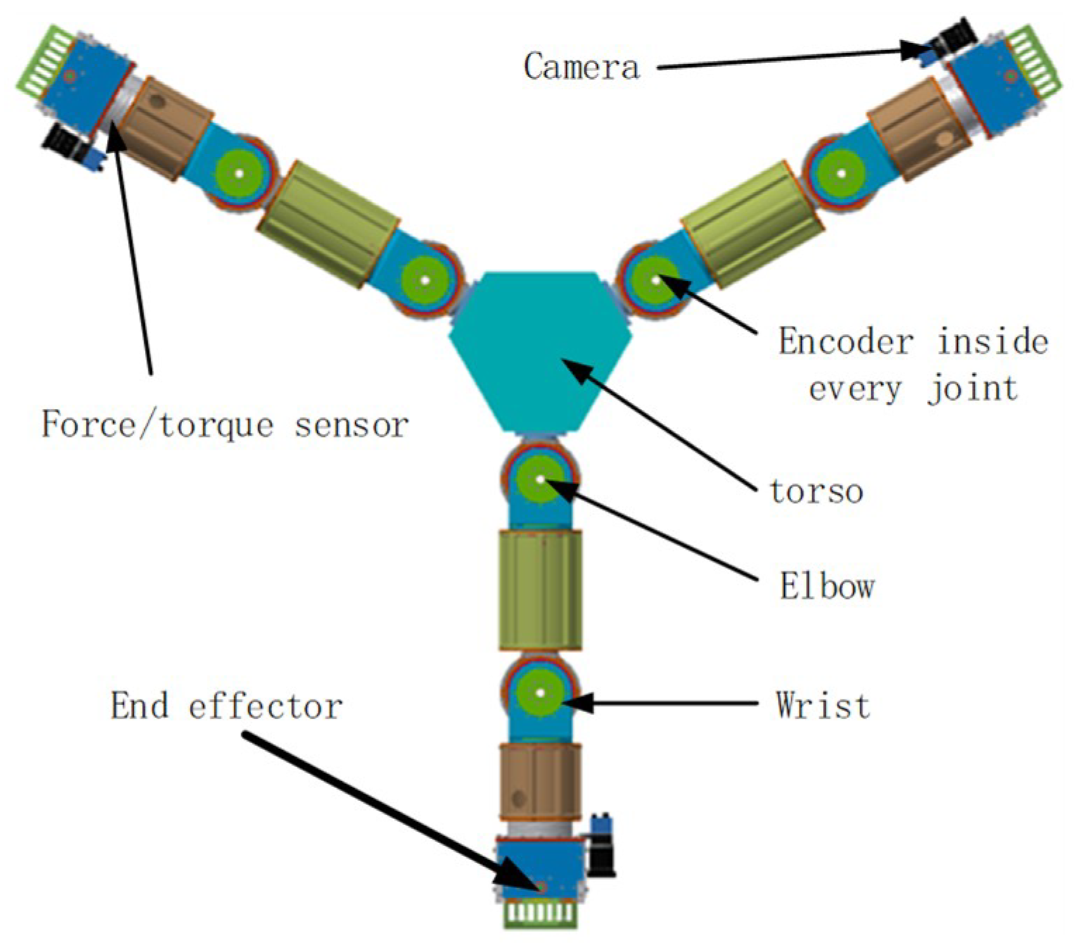
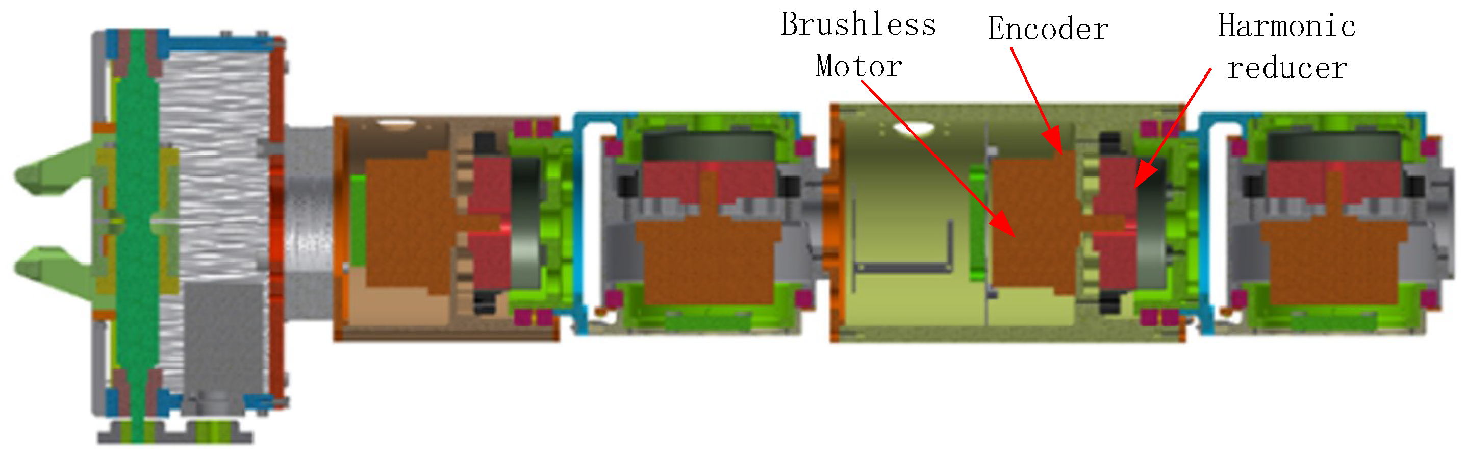
2.2. Structural Design and Key Technologies
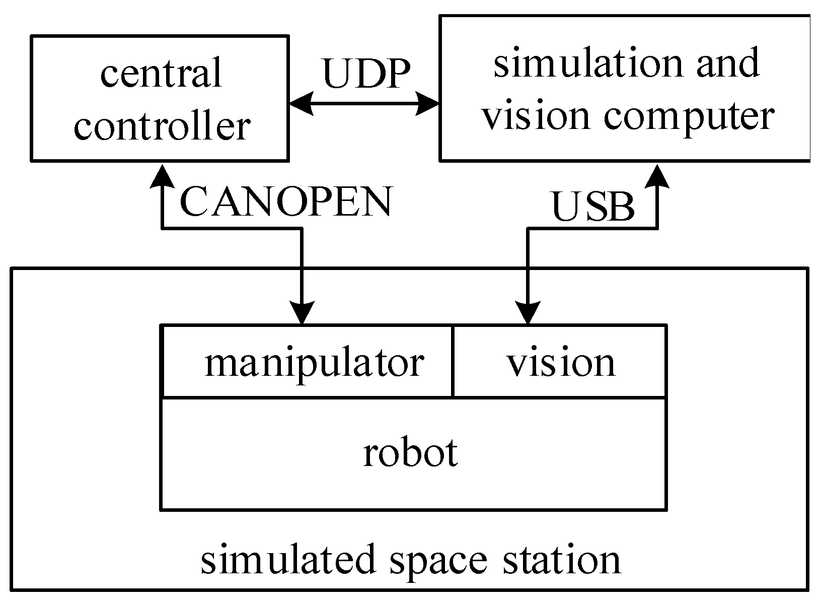
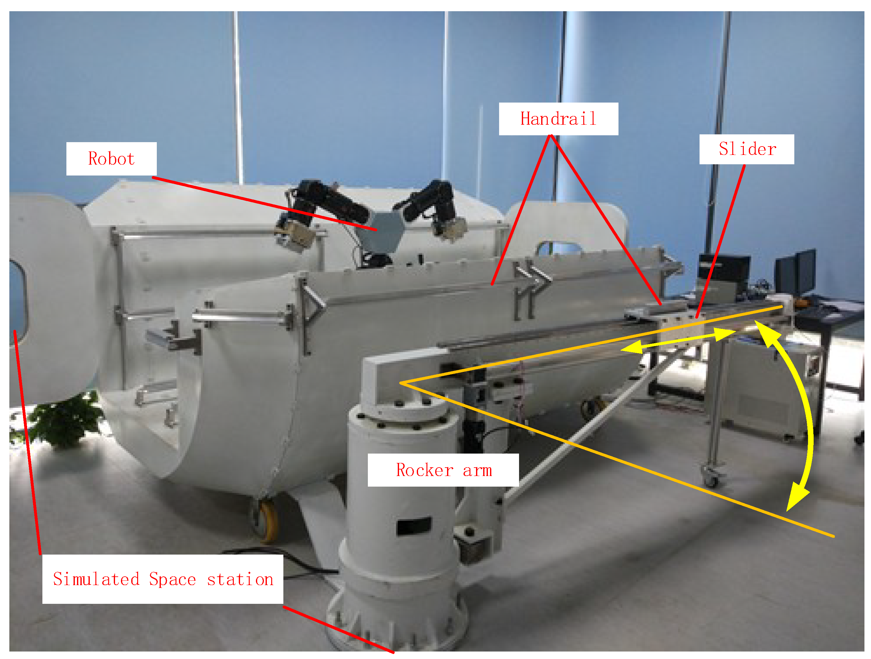
The Beijing Astronaut Robot consists of three identical 4-DOF arms, three end effectors, and a torso, as shown in Figure 2.
The robot mimics the grasping of a chameleon, and its motion and operation mechanism is composed of three identical arms with end effectors, and has 15 degrees of freedom in total. Each arm consists of a wrist with three rotational degrees of freedom and an elbow with one rotational degree of freedom, a total of 3 × 4 = 12 degrees of freedom of motion. The end effectors have 3 × 1 = 3 degrees of freedom. In order to identify the environmental changes and determine its own state, the robot is equipped with a monocular vision camera, 6-dimensional force/torque and other sensors, like encoders in every joint, as shown in Figure 2. The overall scheme of the robot is shown in Figure 3.
It is researched that the motion of the chameleon in a complex environment is very stable, this feature coincides with the robot’s mobile demand [12]. Therefore, the design of our robot’s bionic motion and operating mechanism draws on the characteristics of a chameleon. More specifically, the design of the robot arms’ degrees of freedom and motion pattern draws on the skeletal structure of a chameleon [10,13]. The bionic robot arm and the end effector of the Beijing Astronaut Robot are shown in Figure 4.
In order to make the robot end effector grasp the handrail and obtain sufficient force and torque to prevent the occurrence of sliding or rotation [1], we designed a claw driven by a screw (as shown in Figure 5). The rotation of the screw driven by a motor is converted into the opening and closing of the claw [14,15]. When the lead angle of the screw is smaller than the self-locking angle, the transmission mode has self-locking property, that is, the sliders can only be driven by the rotation of the screw, but the screw cannot be driven by stressing the sliders. Therefore, even if the motor’s power is cut off, the gripper can still grasp the handrail to ensure the safe motion of the robot.

2.3. Testing Layout

In order to test the motion performance of the robot, a control structure is designed, as shown in Figure 6.
The motion test of the robot is done in the simulated space station. The Beijing Astronaut Robot can accomplish rolling, walking by grasping the handrails, and sliding driven by the rocker arm shown in Figure 7.
The central controller is in charge of the kinematics calculation, trajectory planning and sends motion instructions to every joint trough CANopen (a higher-layer protocol for the CAN bus) [16]. The simulation and visual processing computer completes 3D motion simulations, hand-eye vision processing, and task settings of the robot. The computer can capture images by communicating with hand-eye cameras through USB 2.0, and processes the images to obtain the pose of the target. The computer sends task and vision processing information to the central controller. Meanwhile, it receives the data of joint motion from the central controller through a UDP (User Datagram Protocol) network [17], so that the computer can preview the motion of the robot.

3. Testing Results

The performance tests include motion performance tests of a single arm, system simulation tests, and motion performance tests of the whole robot.

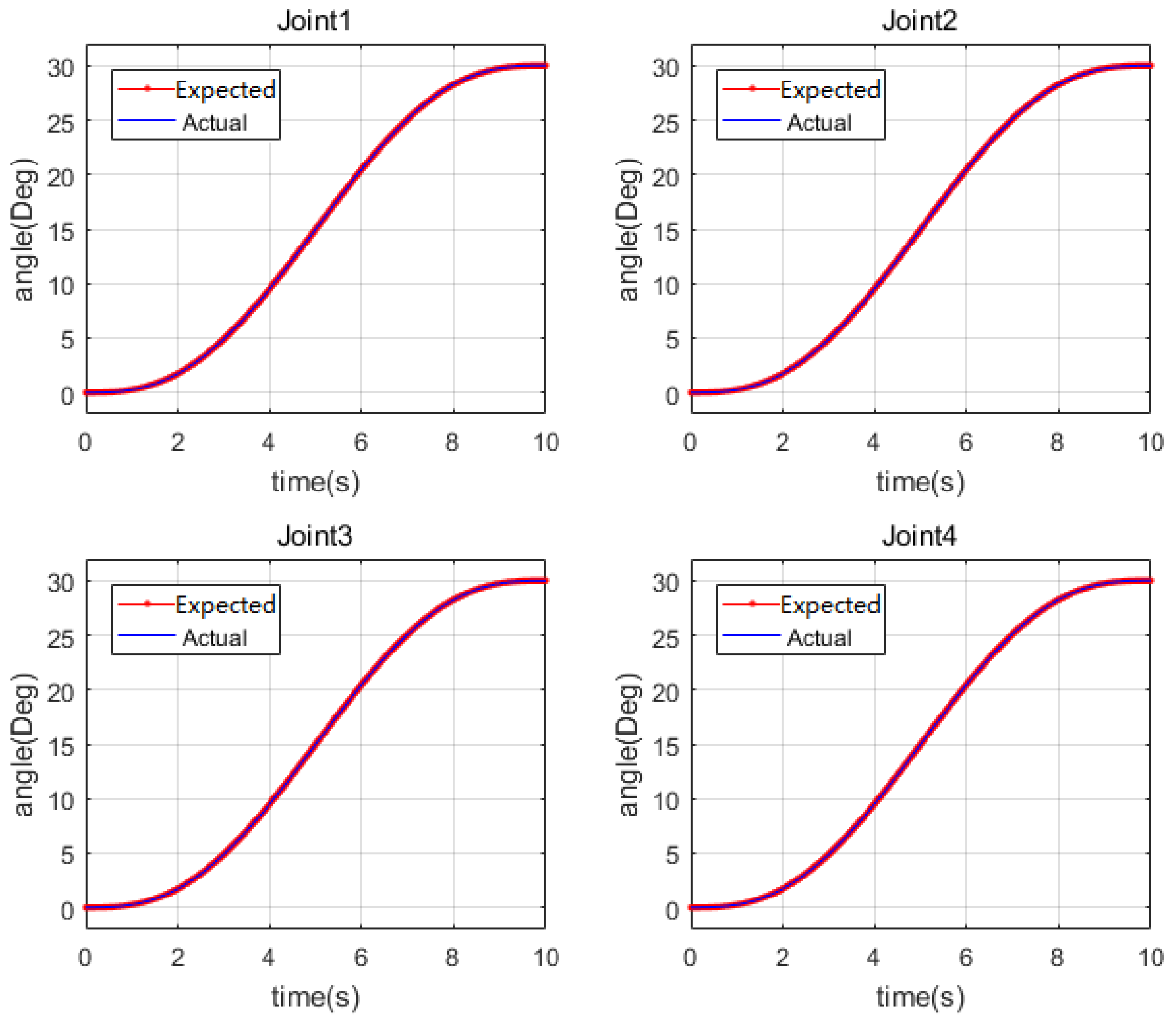
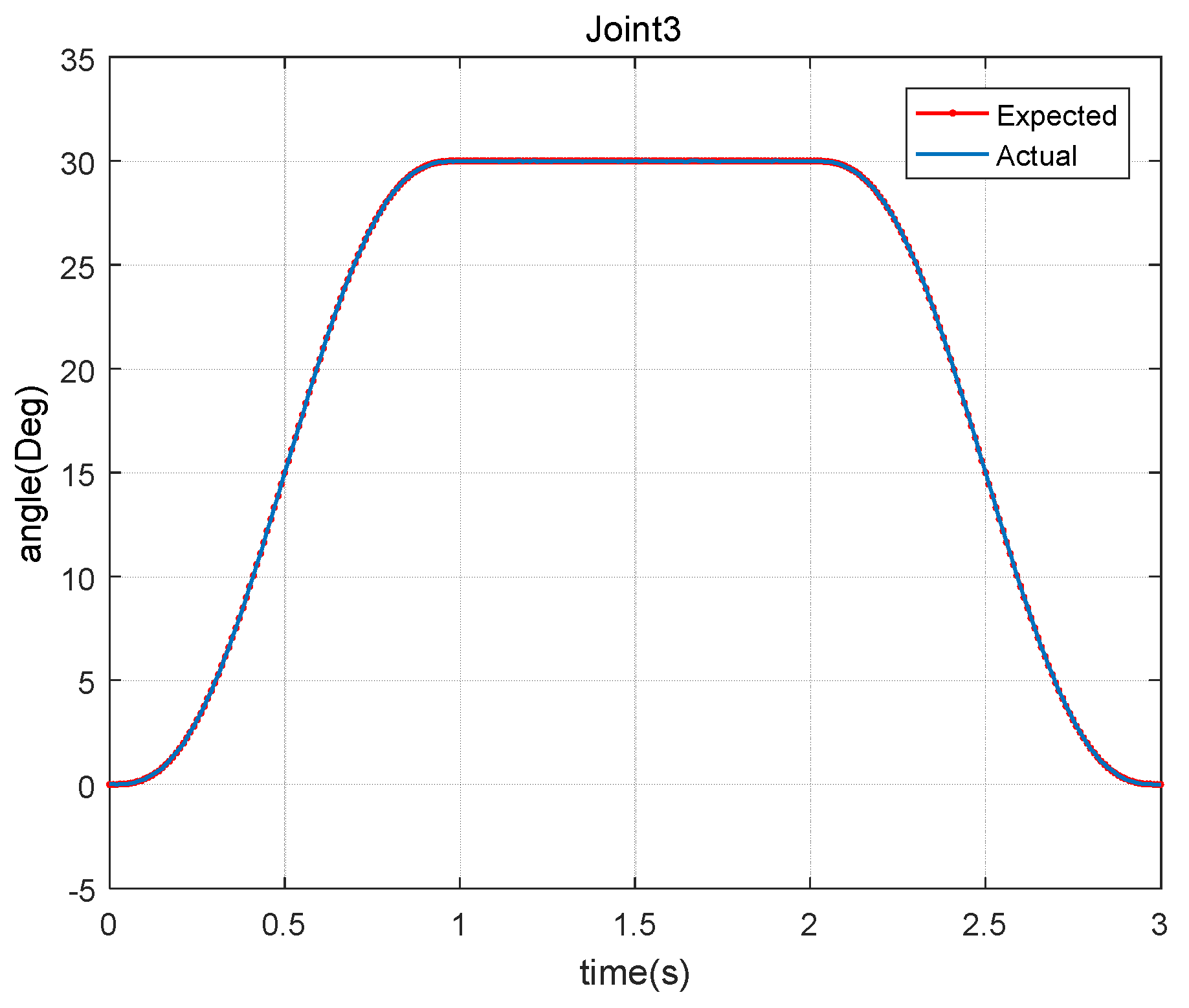
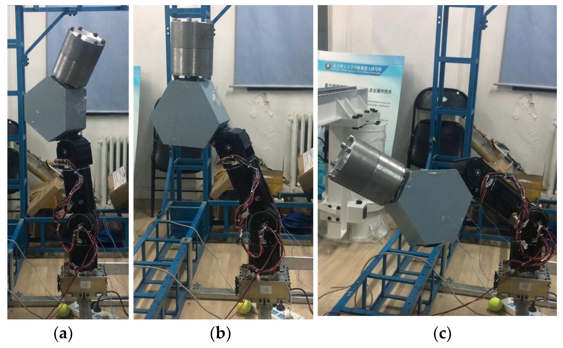
3.1. Motion Performance Test of A Single Arm

The motion performance of a single arm is the basis for the robot to complete all the tasks. Thus, we test the motion performance of a single arm to get the properties of the robot, like the motion accuracy, and the loading capability. We test the motion performance of a single arm under both no-load and load states by sending motion instructions and obtain the actual motion of joint from the encoder feedback.
The end effector of one arm holds the handrail while the other two are unmounted from the torso of the robot. We hope to test all joints at the same time, and all joint angles are set to the same value. Simple geometric analysis shows that when the joints of the single arm move from 0° to 30°, the arm of the robot reaches a harsh condition, which can lay a foundation for the following load test. In the actual motion of the robot, we want the robot’s displacement, velocity, and acceleration to change smoothly, and we can give the first and last values of the three. Thus, in the test, every joint rotates smoothly from using a fifth-order polynomial.
The robot finishes the planned motion under the no-load condition; the process is shown in Figure 8.
In the process, the expected angles sent by the central controller and actual motion angles measured by the encoder of every joint is shown in Figure 9. The location of joints 1–4 are shown in Figure 3. It can be seen that the expected and actual angles are consistent, basically, and the maximal error is 0.03°.
In order to check the performance of a single arm in the normal working condition, we add a 20 kg load, which is equivalent to the other two arms on the torso, and the process of motion is shown in Figure 10. Although the mass distribution is not exactly the same as the case where all three arms of the robot are installed, they are basically similar. Compared to the actual working conditions, such a loading method results in a slightly poor mass distribution causing a higher requirement for the single arm load capacity. Therefore, the load test can reflect whether the load capacity of each joint of one arm can meet the needs. It is proved that the arm can complete the planning motion well under the 20 kg load, and the maximal error is 0.04°.

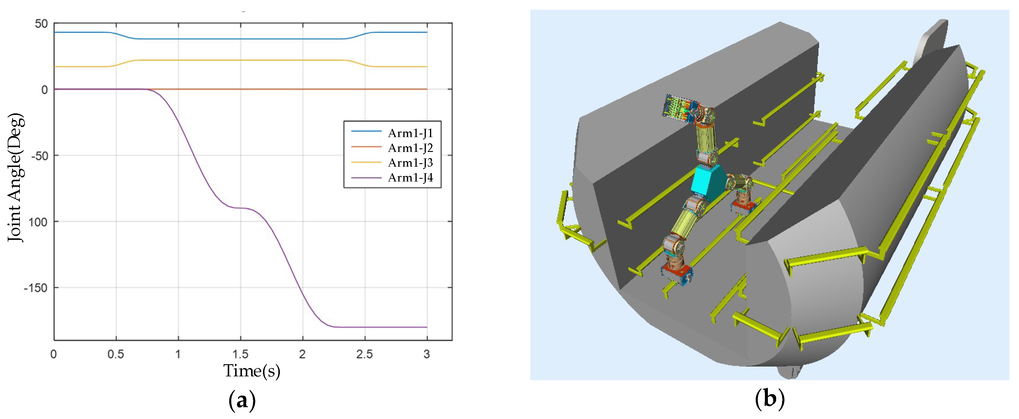
3.2. System Simulation Test

Due to the large degree of freedom of the robot and the complex kinematics, the robot motion simulation system (as shown in Figure 11) is developed and becomes one of the ideal platforms for studying the kinematics of the robot. At the same time, the complexity of the space station structure has high requirements on the operation of the robot, resulting in a complexity of the robot’s motion planning. Fortunately, the development of the simulation system can provide an auxiliary and verification platform for the motion planning of the robot.
Before the motion performance test of the whole robot, we simulated the motion of robot with the simulation and visual processing computer. After the motion planning data has been entered into the simulation system, we can visually see the motion effect of the robot. With such a system, we can quickly check the robot's trajectory for obvious problems, ensure that the trajectory planning is correct, and then transfer it into the actual robot system, thus ensuring the safety of the robot motion.

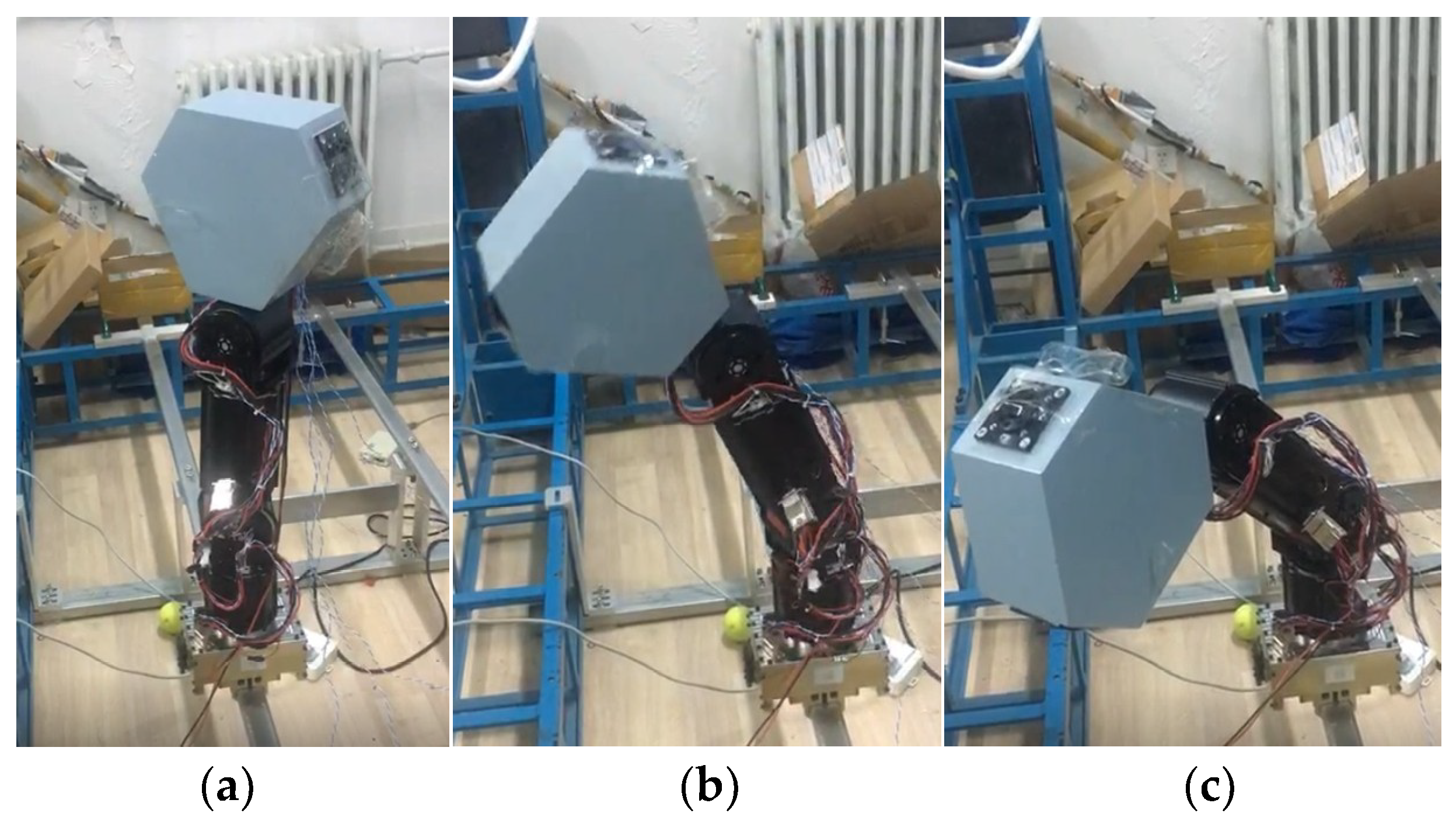
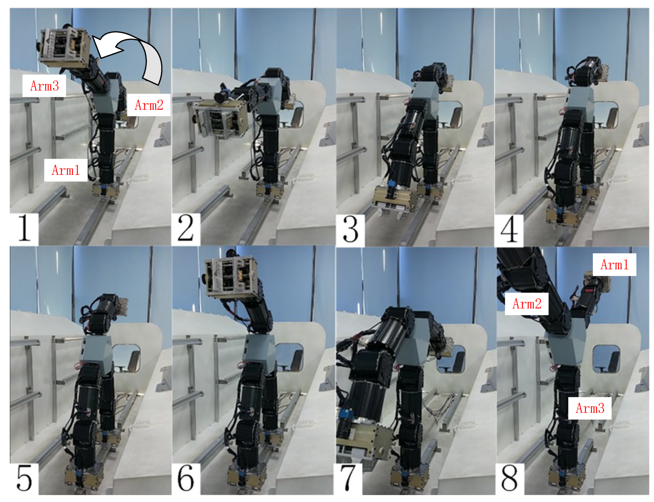
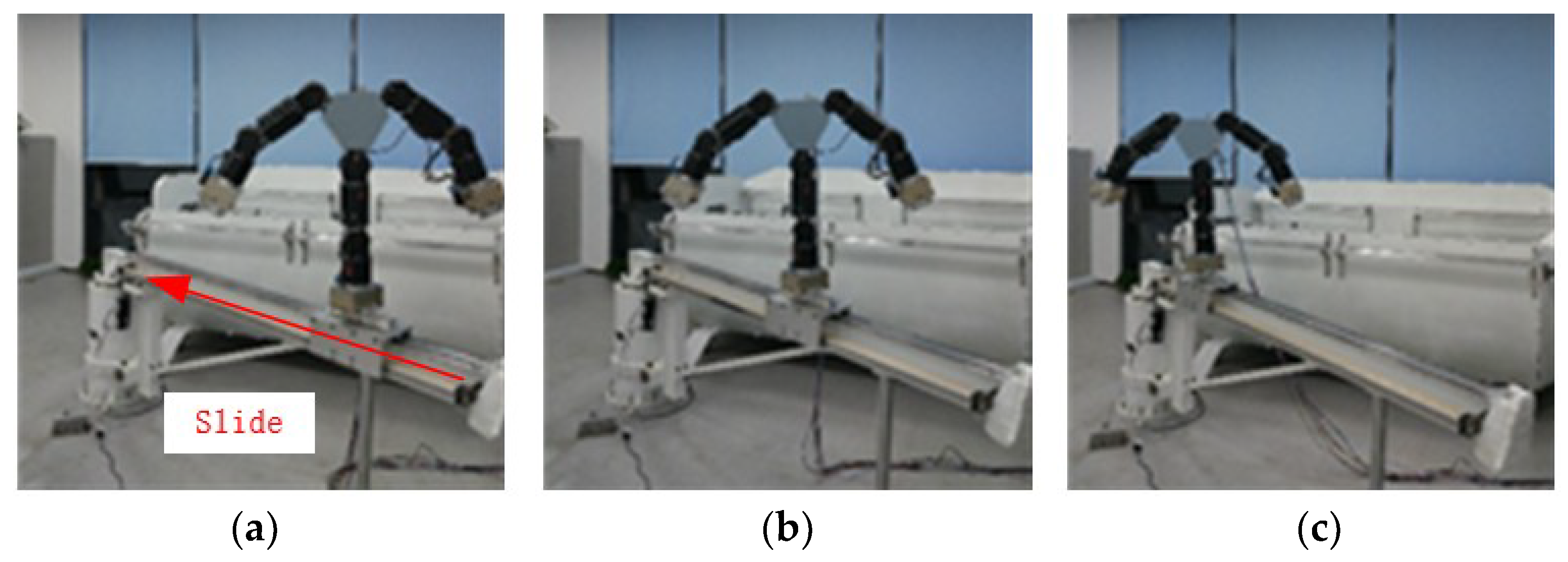
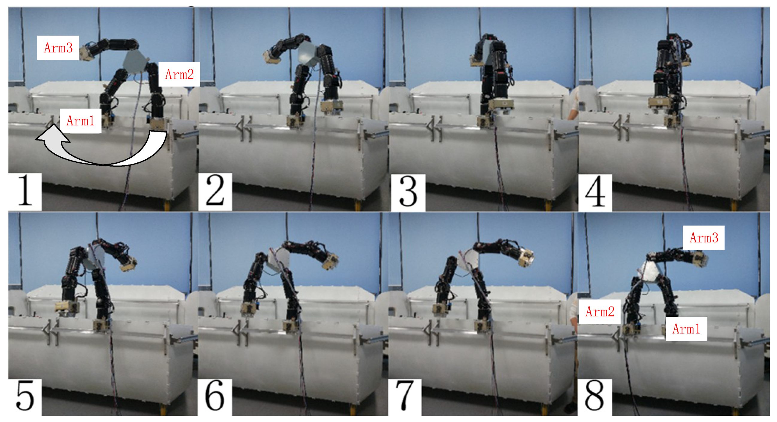
3.3. Motion Performance Test of the Robot

After the motion performance test of a single arm and the system simulation test, we test the motion performance of the robot with the prototype. The central controller receives the revolving command from the simulation and visual processing computer, and send motion data of every joint to the prototype, so the robot revolves according to the data.
We tested three motion types in total: walking, rolling, and sliding, as shown in Figure 12, Figure 13 and Figure 14.
In the above modes, the joint most likely to get a large motion error is the joint 3 of arm 1 with the largest load in the rolling mode. The planned motion curve and the actual value read by the encoder are shown in Figure 15. The results show that the robot joint motion is stable, and its maximum error is 0.04°, which is consistent with the one-arm test results. The actual motion of the robot has indirectly demonstrated the accuracy of the joint motion, so it is unnecessary for the motion data for every joint to be listed.
In order to allow the robot to reach a specific working position outside the space station with the aid of a large space robot arm, an electric slide rail is arranged on the robot arm. The robot grasps the handrail on the slider driven by the electric slide rail to realize the sliding motion. In the test, a 2-DOF (yaw and telescopic) rocker arm is used to simulate the large space robot arm. The motion of the sliding mode is shown in Figure 14.

4. Discussion and Conclusions

Based on analysis of the features of the extravehicular environments, this paper learns from the mechanism of a chameleon, and creatively proposes a kind of astronaut robot that can help astronauts perform dangerous and prolonged work. The robot has three modular arms, each arm has four rotary joints, an end effector and a monocular vision system. The total mass of the robot is 30 kg, and each arm length is 700 mm, which meet the design requirements. The end effectors are designed with a self-locking ability to grasp the handrail firmly so the robot can move freely outside the space station via handrails. Numerous experiments, such as a single-arm test, simulation tests, and integrated ground verification, show that the astronaut robot has excellent motion performance. In the future, we will study how to save the power of our robot by drawing on the design of microrobots, so that it consumes less power from the space station power source [18].

Author Contributions

Conceptualization: H.L. and M.C.; structural design: Z.S. (Zeyuan Sun) and H.L.; software: Z.S. (Zhenzi Song) and Y.M.; funding acquisition: Z.J.

Funding

The authors would like to acknowledge the National Natural Science Foundation of China (61733001, 61573063, 61503029, U1713215) and Tianjin Science and Technology Plan Project (17YFCZZC00500) for their support and funding of this paper.

Conflicts of Interest

The authors declare no conflict of interest. The funders had no role in the design of the study; in the collection, analyses, or interpretation of data; in the writing of the manuscript, and in the decision to publish the results.

References

  1. Thuot, P.J.; Harbaugh, G.J. Extravehicular activity training and hardware design consideration. Acta Astronaut. 1995, 36, 13–16. [Google Scholar] [CrossRef]
  2. Macelroy, R.D.; Smernoff, D.T. Controlled Ecological Life Support System: Regenerative Life Support Systems in Space. Available online: https://ntrs.nasa.gov/search.jsp?R=19880002869 (accessed on 1 September 1987).
  3. Zhang, T.; Chen, Z.; Wang, X.; Liang, B. Overview and Prospect of Key Technologies of Teleoperation of Space Robot. Aerosp. Control Appl. 2014, 40, 1–9. [Google Scholar]
  4. Doetsch, K. Canada’s role on space station. Acta Astronaut. 2005, 57, 661–675. [Google Scholar] [CrossRef] [PubMed]
  5. Diftler, M.A.; Culbert, C.J.; Ambrose, R.O.; Platt, R.J. Evolution of the NASA/DARPA Robonaut control system. IEEE ICRA 2003, 2, 2543–2548. [Google Scholar]
  6. Gibbs, G.; Sachdev, S. Canada and the international space station program: overview and status. Acta Astronaut. 2002, 51, 591–600. [Google Scholar] [CrossRef]
  7. Abramovici, A. The Special Purpose Dexterous Manipulator (SPDM) Systems Engineering Effort—A successful exercise in cheaper, faster and (hopefully) better systems engineering. J. Reduc. Space Mission Cost 1998, 1, 177–199. [Google Scholar] [CrossRef]
  8. Robotics, M.D. Mobile Servicing System—Data Sheet. MD Robotics, Brampton, Ontario, Canada 2002. Available online: http://www.spacenet.on.ca/data/pdf/canada-in-space/mss-ds.pdf (accessed on 23 January 2002).
  9. Ni, W.; Zhang, B.; Yang, H.; Li, H.; Jiang, Z.; Huang, Q. Foot/hand design for a chameleon-like service robot in space station. In Proceedings of the 2013 IEEE International Conference on Robotics and Biomimetics (ROBIO), Shenzhen, China, 12–14 December 2013; pp. 215–220. [Google Scholar]
  10. Fischer, M.S.; Krause, C.; Lilje, K.E. Evolution of chameleon locomotion, or how to become arboreal as a reptile. Zoology 2010, 113, 67–74. [Google Scholar] [CrossRef] [PubMed]
  11. Coleshill, E.; Oshinowo, L.; Rembala, R.; Bina, B.; Rey, D.; Sindelar, S. Dextre: Improving maintenance operations on the international space station. Acta Astronaut. 2009, 64, 869–874. [Google Scholar] [CrossRef]
  12. Prahlad, H.; Pelrine, R.; Stanford, S.; Marlow, J.; Kornbluh, R. Electroadhesive Robots—Wall Climbing Robots Enabled by a Novel, Robust, and Electrically Controllable Adhesion Technology. In Proceedings of the IEEE ICRA and Automation, Pasadena, CA, USA, 19–23 May 2008; pp. 3028–3033. [Google Scholar]
  13. Hui, L.; Marco, C.; Qiang, H.; Giuseppe, C. A Chameleon-Like Service Robot for Space Station. In Proceedings of the International Workshop on Bio-Inspired Robots, Nantes, France, 6–8 April 2011. [Google Scholar]
  14. Marco, C. Grasping in Robotics; Springer: Berlin, Germany, 2013; pp. 117–120. ISBN 978-1-4471-4664-3. [Google Scholar]
  15. Sabatini, M.; Palumbo, N.; Gasbarri, P. Virtual and Rapid Prototyping of an Underactuated Space End Effector. J. Robot. Autom. 2017, 1, 10–21. [Google Scholar]
  16. Farsi, M.; Ratcliff, K.; Barbosa, M. An introduction to CANopen. Comput. Control Eng. J. 1999, 10, 161–168. [Google Scholar] [CrossRef]
  17. Postel, J. User Datagram Protocol. Available online: https://tools.ietf.org/html/rfc768 (accessed on 28 August 1980).
  18. Baglio, S.; Castorina, S.; Fortuna, L.; Savalli, N. Modeling and design of novel photo-thermo-mechanical microactuators. Sens. Actuators A 2002, 101, 185–193. [Google Scholar] [CrossRef]
Figure 1. Handrails on extravehicular surface with appearance and dimensions.
Applsci 08 01342 g001
Figure 2. Overall structure of the robot.
Applsci 08 01342 g002
Figure 3. DOF (degree of freedom) configuration of the Beijing Astronaut Robot.
Applsci 08 01342 g003
Figure 4. Bionic robot arm and end effector.
Applsci 08 01342 g004
Figure 5. (a) The schematic diagram of mechanism of the claw; (b) The overall structure of the end effector.
Applsci 08 01342 g005
Figure 6. Control structure of the Beijing Astronaut Robot.
Applsci 08 01342 g006
Figure 7. The actual test environment of the robot.
Applsci 08 01342 g007
Figure 8. The motion of single arm under the no-load condition. (a) Motion start; (b) In the process of motion; (c) Motion complete.
Applsci 08 01342 g008
Figure 9. The motion of four joints under no load.
Applsci 08 01342 g009
Figure 10. The motion of single arm under 20 kg load. (a) Motion start; (b) In the process of motion; (c) Motion complete.
Applsci 08 01342 g010
Figure 11. The simulation of the robot’s motion. (a) The motion planning data; (b) Display interface of robot motion simulation system.
Applsci 08 01342 g011
Figure 12. Walking mode. In this mode, arm 2 is initially located to the right of arm 1. During walking, arm 1 grasps the handrail, then arm 2 releases, the robot rotates 180° around arm 1. Then arm 1 reaches the left side of arm 2, and arm 2 grasps the armrest to complete one step of the robot. In the next step of walking, the robot rotates around arm 2 to complete the walking action. Arm 1 and arm 2 move alternately to achieve continuous walking of the robot.
Applsci 08 01342 g012
Figure 13. Rolling mode. In this mode, arm 1 grips the handrail, arm 2 rises, the center of gravity of the robot is adjusted, and then arm 3 drops and grasps the handrail. Finally, arm 1 rises to complete a tumbling motion. The three arms alternately run to achieve continuous rolling of the robot.
Applsci 08 01342 g013
Figure 14. Sliding Mode. (a) Motion start; (b) In the process of motion; (c) Motion complete.
Applsci 08 01342 g014
Figure 15. The motion of the root joint of arm 1.
Applsci 08 01342 g015

