1. Introduction
Body Centred Cubic (BCC) Vanadium-based alloys have been studied intensively since Reilly et al. reported that vanadium hydride can store 3.8 wt % of hydrogen (i.e., dihydride VH
2) and has a reversible capacity of about 2 wt % [
1,
2,
3]. For hydrogen storage applications, one limitation of these alloys is the high price of vanadium. Thus, a low-cost alloy (i.e., with lower vanadium content) could be more attractive for industrial production. Following this idea, the effect of the addition of other transition elements has been studied by many groups [
4,
5,
6,
7,
8,
9,
10,
11,
12]. In general, upon substitution, the reversible storage capacity decreases, but for most cases, the hydrogen capacity is around 2 wt %, which is acceptable for some applications.
Metal hydrides containing vanadium may be too expensive to be commercially viable. One way to reduce cost is then to replace vanadium by the less expensive ferrovanadium [
9,
11,
13,
14,
15,
16,
17,
18,
19]. For example, Taizhong et al. found that the alloy TiCr
1.2(FeV)
0.6 has a total hydrogen capacity of 3.0 wt % and a reversible capacity of 1.8 wt % [
9]. Kim et al. showed that the as-cast Ti
0.85Zr
0.13(FeV)
0.56Mn
1.47Ni
0.05 alloys was made of a C14 Laves phase and the FeO phase. The origin of the FeO phase was the replacement of V by FeV. However, annealing at 1000 °C for one hour resulted in a single phase with C14 Laves phase with a reversible hydrogen capacity of 1.6 wt %. Santos et al. reported that the alloys TiMn
0.9(FeV)
1.1 and TiMn
1.1(FeV)
0.9 have faster activation kinetics than their pure vanadium counterpart [
16]. The total hydrogen capacity was lower for the ferrovanadium containing alloys, but the reversible capacity was higher due to the modification of the plateau pressures. Recently, Mao et al. synthesized (FeV80)
48Ti
26Cr
26 by the hydride powder sintering method [
11]. They found that the hydrogen capacity was reduced when compared to the melted alloy. However, adding 4 at% of Ti the sintered sample was shown to have similar hydrogen absorption-desorption capacities than the melted sample. Sakaki et al. studied TiZrMn BCC alloy for metal hydride actuators [
19]. They showed that ferrovanadium could be used for cost reduction and that the Al impurity in ferrovanadium could reduce the hysteresis factor.
Recently, we reported the investigation of Ti
1.56V
0.36Cr
1.08 Cr and Ti
1.26V
0.63Cr
1.11 alloys, to which Zr
7Ni
10 was added to enhance the activation process [
20,
21]. In order to decrease the cost of these alloys, we investigated the partial replacement of vanadium by ferrovanadium (FeV). For both alloys 50 at%, vanadium was replaced by ferrovanadium thus obtaining Ti
1.56V
0.18(FeV)
0.18Cr
1.08 and Ti
1.26V
0.315(FeV)
0.315Cr
1.11 alloys. The effects of partial replacement of V by FeV in these Ti-V-Cr alloys on the crystal structure, microstructure, and thermodynamics parameters are presented here.
2. Materials and Methods
The raw elements were purchased from Alfa-Aesar and had the following purities: Ti (99.95%), V (99%), Cr (99%), Zr (99.95%), and Ni (99.7%). The ferrovanadium alloy (FeV) had a composition of 79.88 wt % V; 16.26 wt % Fe; 3.74 wt % Al; 0.09 wt % Si; and, 0.03 wt % Cr.
To facilitate the first hydrogenation (activation) 4 wt % of Zr
7Ni
10 alloy was added to Ti
1.26V
0.63Cr
1.11 and Ti
1.56V
0.36Cr
1.08 alloys using the following synthesis method. In a first step, both xTi-yV-zCr and Zr
7Ni
10 alloys were melted independently. In the second step, both of the alloys were crushed separately in a mortar and pestle, mixed in the right proportion, and remelted together. This process is thereafter called co-melt. More details about this process could be found in our previous paper [
21]. Replacement of 50 at% of vanadium by ferrovanadium was done in both Ti
1.56V
0.36Cr
1.08 and Ti
1.26V
0.63Cr
1.11 alloys. In order to simplify, the name ‘50% FeV’ refer to the composition were 50 at% of vanadium was replaced by ferrovanadium and ‘100% FeV’ to the composition where 100 at% of vanadium was replaced.
In casting, each sample was turned over and melted three times to ensure homogeneity. The X-ray diffraction patterns were acquired on a Bruker D8 Focus apparatus using Cu kα radiation. The crystallographic parameters (lattice parameters, crystallite size, and strain) were evaluated by Rietveld’s refinement of the X-ray diffraction patterns using Topas software [
22]. The refined crystal parameters are quoted with three standard deviations.
The microstructure was investigated with a Tescan Vega3 SEM. An Electron Probe Micro Analysis (EPMA, CAMECA SX 100), coupled with Wavelength Dispersive (WDS), was used for mapping the elements.
Pressure-Composition-Isotherms were measured using a home-made Sievert-type apparatus. Each sample was crushed using a mortar and pestle under argon atmosphere to prevent oxidation and then exposed to hydrogen without prior treatment. Activations were performed at room temperature under 2 MPa of H2. Desorptions were performed at 400 °C under dynamic vacuum for 4 h.
3. Results
3.1. Ti1.56V0.18(FeV)0.18Cr1.08 + 4 wt % Zr7Ni10
3.1.1. Microstructure
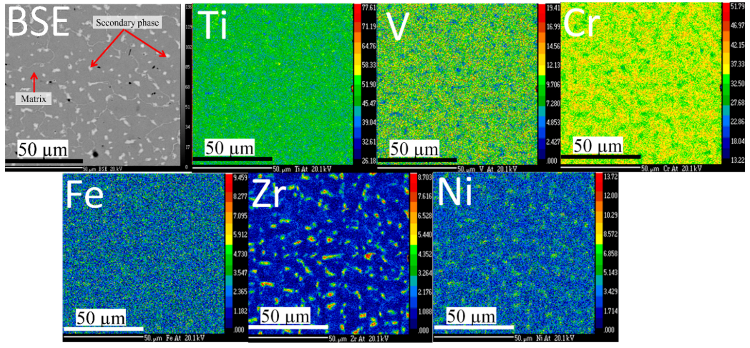
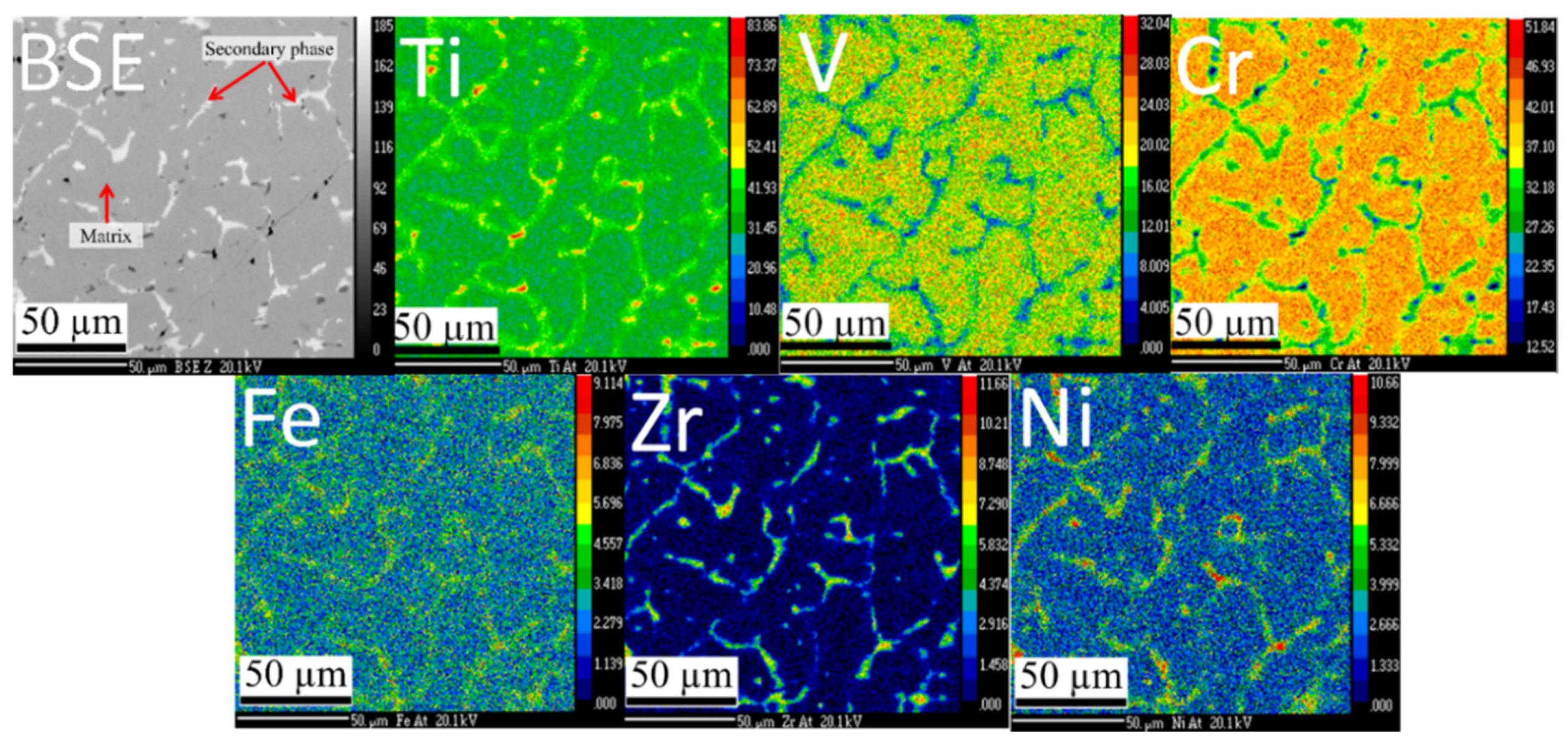
Figure 1 shows the microstructure and elements distribution of the Ti
1.56V
0.18(FeV)
0.18Cr
1.08 + 4% Zr
7Ni
10 co-melt alloy. Two distinct phases are present: a main dark phase and a bright secondary phase. The secondary phase is evenly distributed and the size of each ‘island’ of secondary phase is of the order of a few microns. The element mapping indicates that the secondary phase is rich in zirconium and nickel elements.
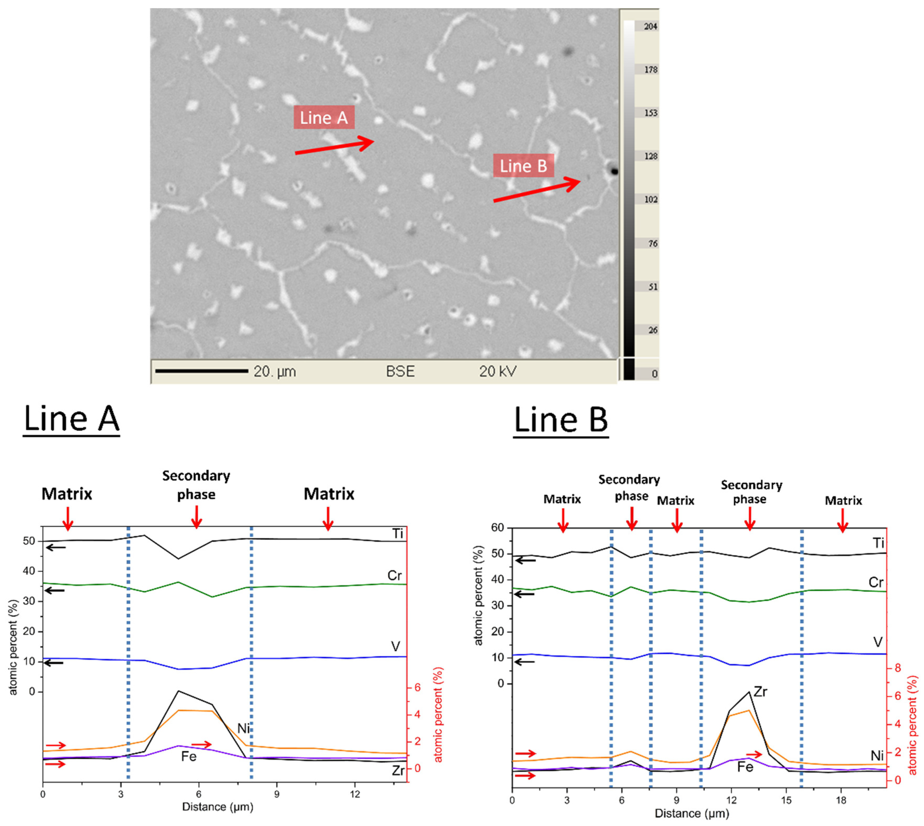
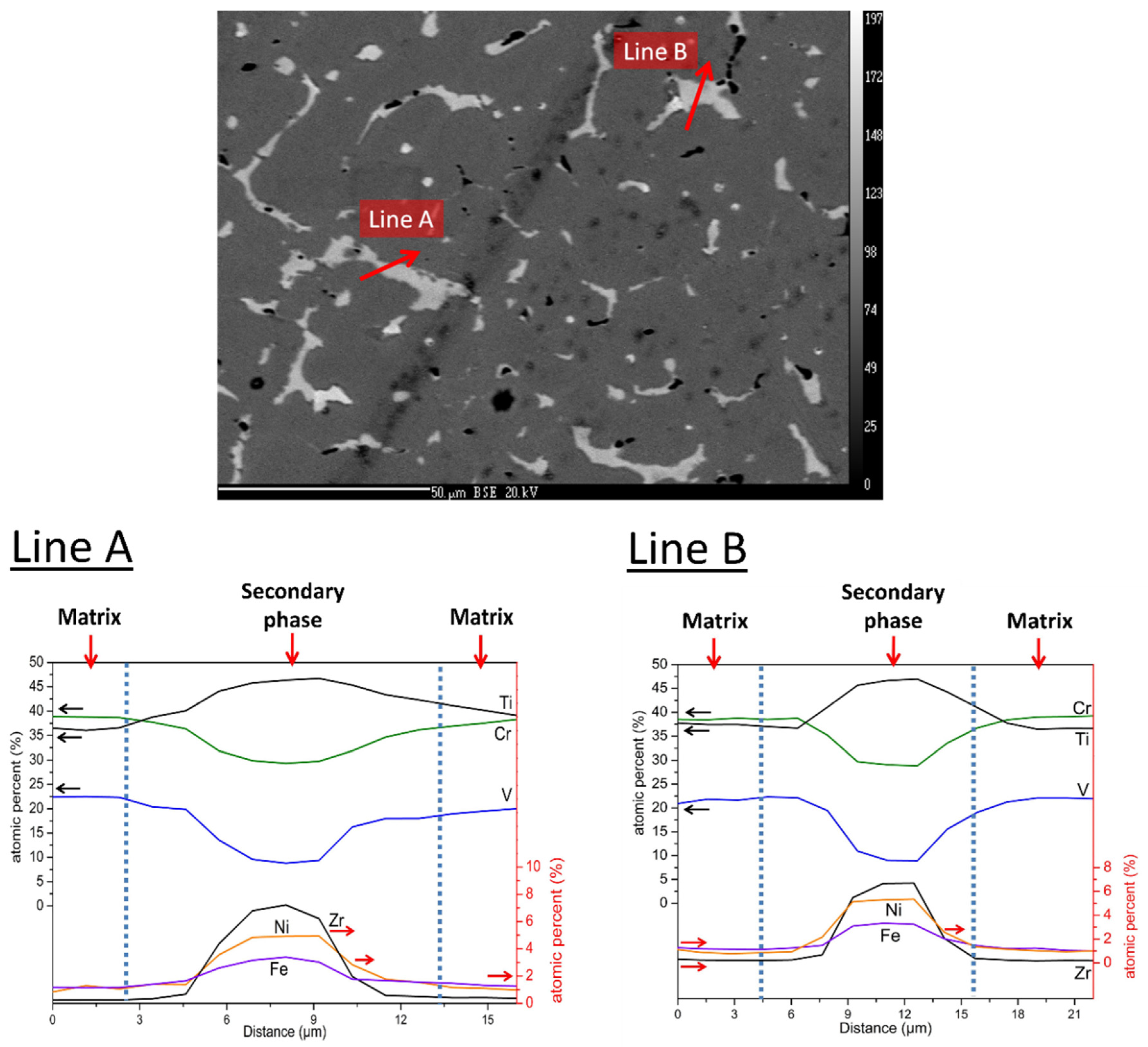
Figure 2 shows a quantitative chemical analysis using EDX. The two lines (A and B on
Figure 2) analysis clearly indicate that the amount of titanium, vanadium, and chromium slightly decrease in the secondary phase when compared to the matrix. Iron and nickel are almost exclusively found in the secondary phase. As far as zirconium is concerned, a small proportion is present in the matrix, but its abundance is much higher in the secondary phase. The quantitative analysis is reported in
Table 1. One can notice in
Table 1 that a relative variation of element abundance between the matrix and the secondary phase can be seen for iron, zirconium, and nickel, while the smallest variations are noticed for titanium and chromium. The matrix phase has a chemical composition that is very close to the nominal one except that zirconium and nickel are is a very low concentration. These two elements are almost exclusively found in the secondary phase, in which vanadium content is much reduced when compared to the matrix, but titanium and chromium concentrations are very similar to the ones that are found in the matrix.
3.1.2. Crystal Structure
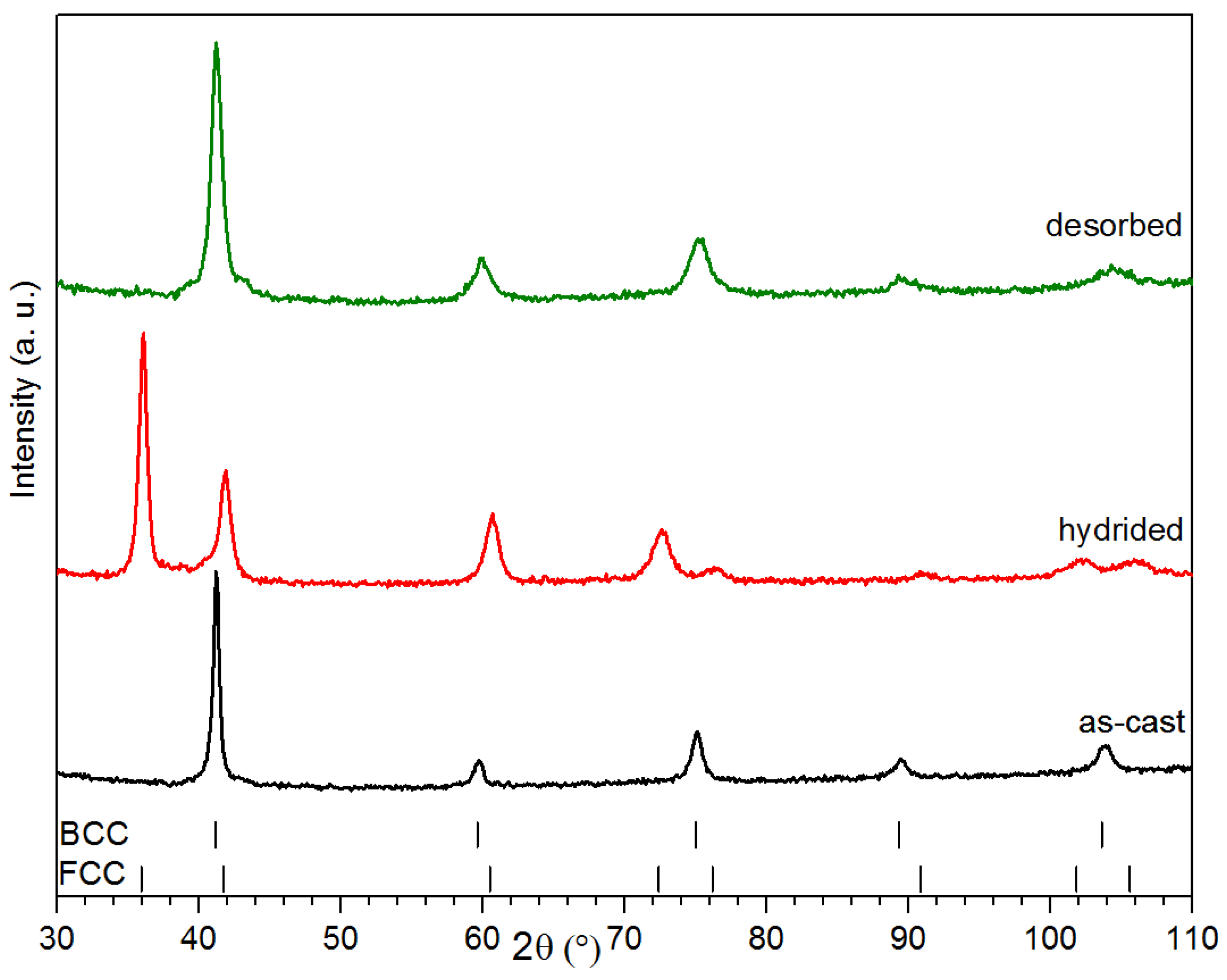
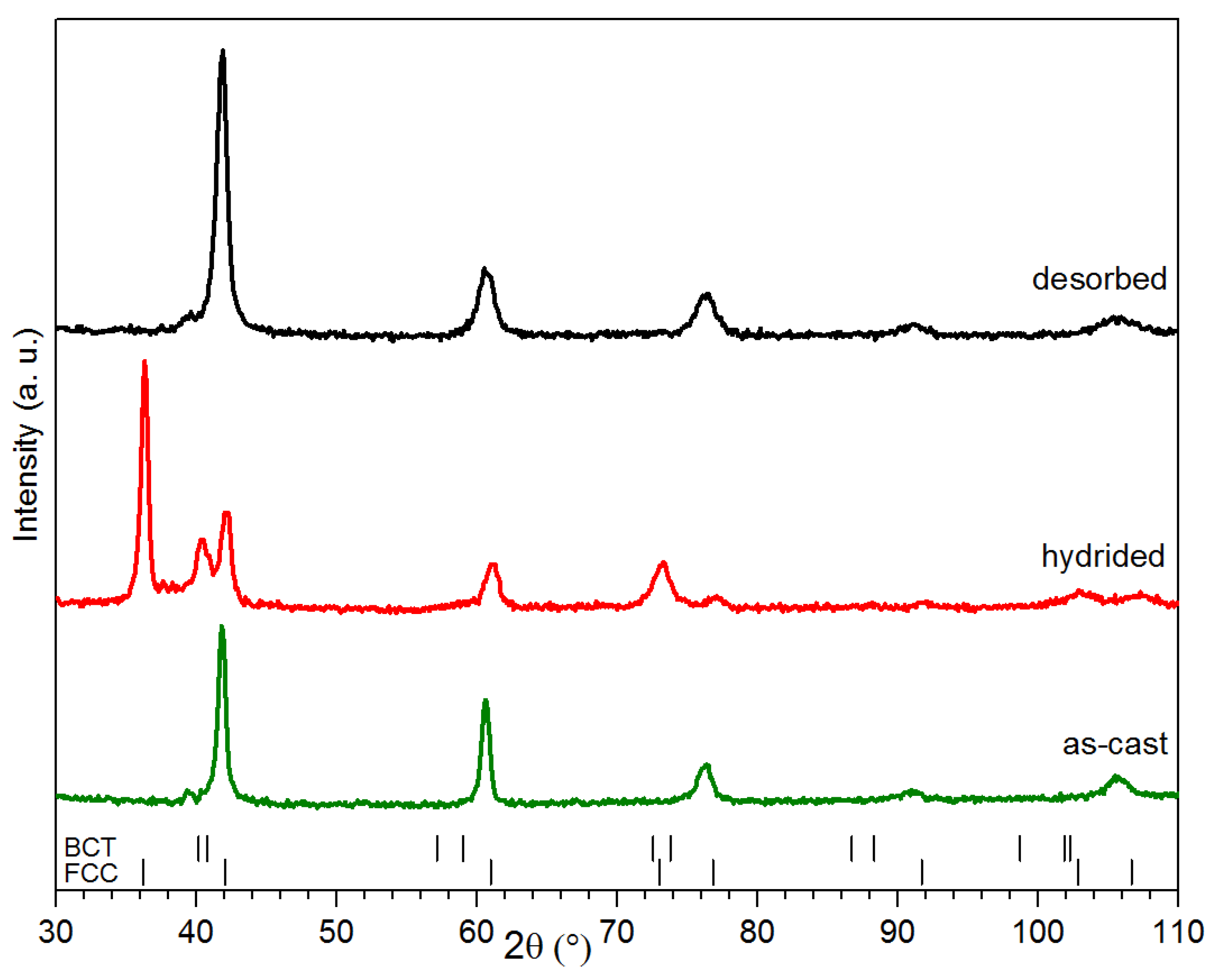
The alloy’s crystal structure was investigated by X-ray powder diffraction. Diffraction patterns of co-melt Ti
1.56V
0.18(FeV)
0.18Cr
1.08 + 4%Zr
7Ni
10 taken in as cast, hydrogenated and dehydrogenated states are shown in
Figure 3. The as-cast pattern only shows the BCC structure and there is no evidence of a secondary phase. As seen in
Figure 1 and
Figure 2, the proportion of secondary phase is quite small, thus making it harder to identify by X-ray diffraction. Also, it is clear from the atomic compositions of both phases presented in
Table 1 that both BCC alloys have an almost similar bulk composition. Therefore, even if the crystal structure of the secondary phase remains unknown, there is a strong probability that it exhibits the same crystal structure as the matrix phase. According to our calculations that are based on the diameter of every element provided by the Shannon’s Table, the average metallic radii in both the matrix and the secondary phase were estimated to be, respectively, 0.1392 nm and 0.1401 nm [
23]. This means that, if the matrix and secondary phase have both a BCC structure and if one of them has a much lower abundance than the other, then it may be effectively impossible to distinguish them using the powder X-ray diffraction technique. Assuming the same crystal structure and the average metallic radius, we calculated a shift in the Bragg’s peaks of only 0.01° at 42° and 0.1° at 104°. As the secondary phase abundance is much lower than the main phase, its peak will be effectively ‘buried’ under the main phase peaks.
Rietveld refinements were performed on the three patterns and results are shown in
Table 2. The values that are reported in this table are essentially identical to the one reported in our previous investigation on the alloy Ti
1.56V
0.36Cr
1.08 + 4%Zr
7Ni
10 [
21]. The main discrepancies are the slightly less important reduction of crystallite size upon dehydrogenation and a larger increase of micro-strain after hydrogenation. Nevertheless, it seems that the partial replacement of vanadium has no important effect on the crystal structure of the BCC alloy.
Rietveld refinements of the patterns that are displayed in
Figure 3 also enable us to estimate the stoichiometry of the hydride sample. From the lattice parameters, the formula unit volume was calculated to be 14.89 Å
3 for the BCC structure of the as-cast sample. Regarding its Face Centred Cubic (FCC) hydride counterpart, a volume of 20.24 Å
3 was estimated, corresponding to an expansion of 5.35 Å
3 per formula unit. Using the Westlake’s criteria claiming a volume change comprised between 2 and 3 Å
3 for each hydrogen atom absorbed, the cell structure expansion is consistent with a dihydride FCC phase (Ti
1.56V
0.36Cr
1.08)H
2.
3.1.3. Hydrogen Storage Properties
The kinetics of the first hydrogenation (activation) under 2MPa of hydrogen at room temperature of the Ti
1.56V
0.18(FeV)
0.18Cr
1.08 + 4%Zr
7Ni
10 and Ti
1.56V
0.36Cr
1.08 + 4%Zr
7Ni
10 alloys are presented in
Figure 4. The activation is similar for both of the alloys, the only difference being a slightly longer incubation time for the ferrovanadium-containing sample. After the incubation time, the absorption proceeds quite rapidly and full capacity is reached in less than 300 s for both pure vanadium and vanadium substituted alloys. The maximum capacity is close to 3.2 wt % of hydrogen, which is slightly higher than other Ti-V based materials that was reported in the literature [
24,
25,
26,
27].
After activation, the samples were desorbed and the pressure-composition isotherm was registered. However, we found out that there was an important reduction of capacity that makes the measurement practically impossible. For this reason, after activation at room temperature, the temperature was increased while keeping the sample under high hydrogen pressure in order to prevent it to desorb. Thereafter, the desorption curve was registered. This procedure was repeated for each isotherm, meaning that every isotherm was measured using a freshly hydrided sample.
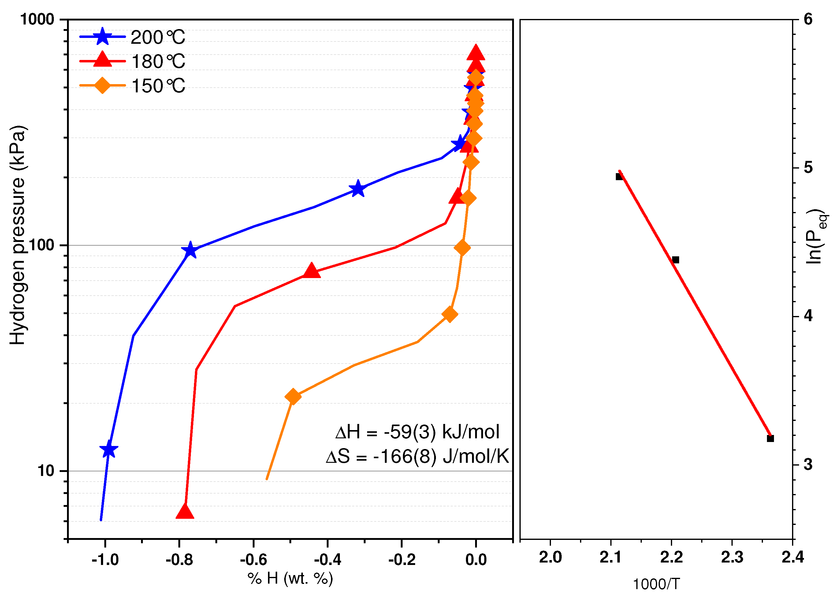
Figure 5 gathers the Pressure Composition desorption isotherms (PCT) that were recorded at 150, 180, 200, and 230 °C. For each temperature, a few measurements were performed with similar results. As the temperature increases, so does the equilibrium pressure. It should be mentioned that the plateau recorded are for the transition from the dihydride to the monohydride. The monohydride plateau is too stable to be recorded with our apparatus. The fact that the plateaus are sloped is probably due to the solid solution nature of the as-cast material. As there is an important reduction of capacity after the first cycle, this may explain why the capacities of various isotherms changed. Further work on cycling properties of this material is needed. This is also the reason why we considered the middle of each plateau as the plateau pressure and not the hydrogen pressure at a given hydrogen concentration. The fact that the capacity increases with temperature is puzzling. One reason may be the lowering of the first plateau that makes the transition from the first to second plateau even more sloping, thus making the measurement of total capacity of the second plateau more difficult. From these pressures, a Van’t Hoff plot was obtained and is reported in
Figure 5. The formation enthalpy of the hydride has been determined to be −59 ± 3 kJ·(mol·H
2)
−1 and its associated entropy −166 ± 8 J·(mol·H
2)
−1·K
−1. The errors have been calculated using the linear fit of the Van’t Hoff plot. As a comparison, the formation enthalpy of the Ti
1.56V
0.36Cr
1.08 + 4% Zr
7Ni
10 hydride has been determined to be −61 kJ·(mol·H
2)
−1 and its associated entropy −169 J·(mol·H
2)
−1·K
−1 [
21].
The high value of the entropy term when compared to the usual one found in metal hydrides (103 to 115 J·(mol·H
2)
−1·K
−1) should be addressed. We recently made a series of experiments on the alloys Ti
1-xV
xCr
37 and found some evidences of an entropy-enthalpy compensation in these alloys. As this is a controversial subject and may be due to some experimental bias, the investigation is still in progress. But, the preliminary results seems to indicate that ΔH is directly proportional to ΔS in these alloys [
28].
3.2. Ti1.26V0.315(FeV)0.315Cr1.11 + 4 wt % Zr7Ni10
3.2.1. Microstructure
The other composition studied was Ti
1.26V
0.315(FeV)
0.315Cr
1.11 doped with 4 wt % of Zr
7Ni
10. This composition was selected because we have already studied the composition Ti
1.26V
0.63Cr
1.11 [
20].
Figure 6 shows the microstructure and elements mapping of as cast co-melt Ti
1.26V
0.315(FeV)
0.315Cr
1.11 + 4 wt % Zr
7Ni
10. It is clear that, as for the previous composition, the alloy is made of a main and a secondary phase where the secondary phase is depleted in chromium and vanadium but is rich in zirconium and nickel.
A quantitative analysis of element abundance is shown in
Figure 7 and the values are reported in
Table 3. The situation is similar to what has been observed for the sample Ti
1.56V
0.18(FeV)
0.18Cr
1.08 + 4% Zr
7Ni
10. It shows that Fe, Zr, and Ni elements are principally found in the secondary phase and that chromium and vanadium concentrations are depleted when compared to the main phase. The only difference with the previous alloy consists of a higher titanium abundance in the secondary phase than in the matrix.
3.2.2. Crystal Structure
Figure 8 presents the X-ray diffraction patterns of the as-cast, hydrided, and desorbed Ti
1.26V
0.315(FeV)
0.315Cr
1.11 + 4% Zr
7Ni
10 alloy.
Table 4 presents the crystal structure parameters, as determined by Rietveld refinements.
The as-cast alloy crystallizes with a BCC structure, as reported for its 100 at% vanadium homologous alloy and has a slightly smaller lattice parameter (0.3062 nm as compared to 0.3074 nm for the Ti
1.26V
0.63Cr
1.11 alloy) [
20]. From the value of lattice parameter of
Table 4, the volume of the formula unit was found to be 14.34 Å
3. The diffraction pattern of the hydride sample clearly shows two phases. One of these phases is the dihydride FCC phase. The other phase is more difficult to determine, and two possibilities were investigated: (1) a BCC phase with hydrogen in solid solution and (2) a monohydride BCT (body centered tetragonal) phase. The Rietveld refinement using both structures gave similar Goodness-of-fit and R-values. It should be noted that the formula unit volume was exactly the same (15.76 Å
3) for both BCT and BCC phases, thus corresponding to an expansion of 1.42 Å
3. It is very close to one fourth of the expansion of the FCC phase. Therefore, even if we could not precisely determine the crystal structure of this second phase, we are confident that it contains about one hydrogen atom for two formula units.
3.2.3. Hydrogen Storage Properties
The kinetics of the hydrogen activation of the Ti
1.26V
0.315(FeV)
0.315Cr
1.11 + 4% Zr
7Ni
10 and co-melt Ti
1.26V
0.63Cr
1.11 + 4% Zr
7Ni
10 are presented in
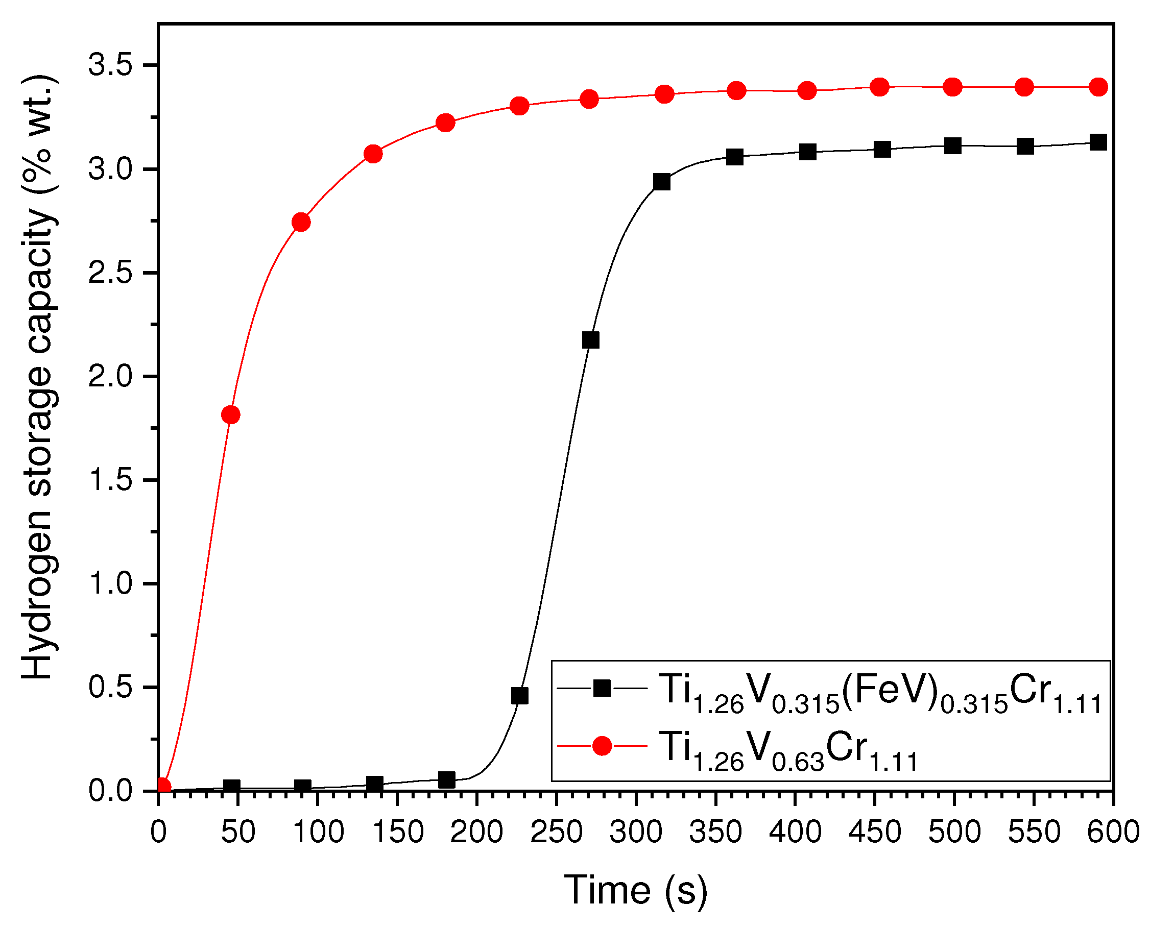
Figure 9. The main difference is clearly that the alloy containing ferrovanadium presents a long incubation time, while hydrogen absorption starts immediately for the alloy with pure vanadium. For both alloys, the full capacity is reached in about 200 s after the reaction started. The maximum capacity of ferrovanadium alloy (3.2 wt % of hydrogen) is slightly smaller than its pure vanadium counterpart (3.4 wt %).
From
Figure 4 and
Figure 9 we see that replacement of vanadium by ferrovanadium made the first hydrogenation starts only after an incubation time. Once the reaction starts, the intrinsic kientics is almost the same as for the alloy without ferrovanadium. The reason of appearance of this incubation time is still not clear. One possible reason may be the nature of the surface of the particles. Alloys that are containing iron may have a thicker oxide on surface, thus making the incubation time longer. But, this hypothesis has to be confirmed by further tests.
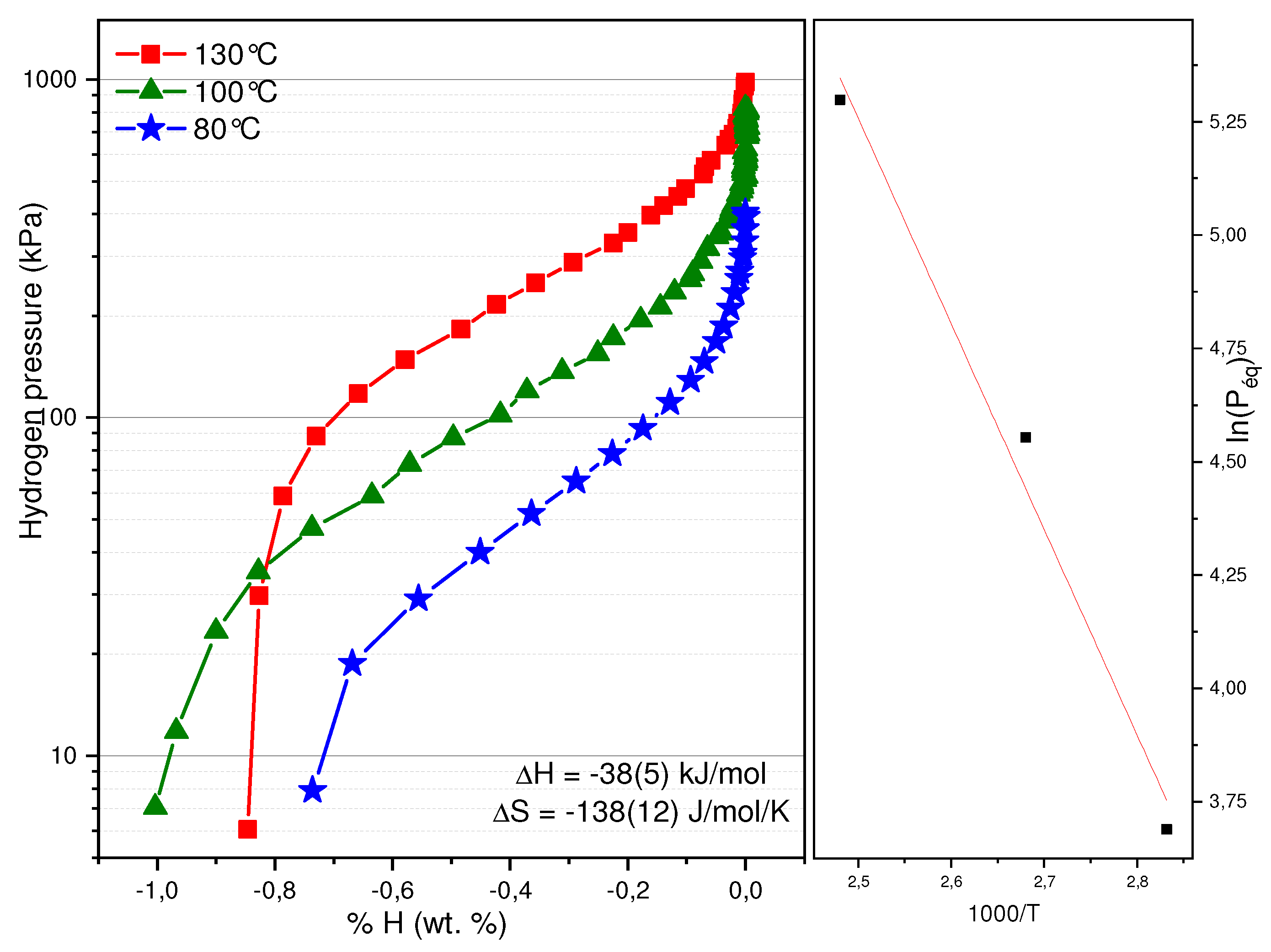
Figure 10 exhibits the Pressure Composition desorption isotherms (PCT) of Ti
1.26V
0.63Cr
1.11 + 4%Zr
7Ni
10 recorded at 80, 100 and 130 °C. Once again, as the temperature increases, so does the equilibrium pressure. A Van’t Hoff plot has been made using the pressure value at the middle of the plateau. The formation enthalpy of the hydride has been determined to be −38 kJ·(mol·H
2)
−1 and its associated entropy −138 J·(mol·H
2)
−1·K
−1. These values are very close to the ones found for Ti
1.26V
0.63Cr
1.11 + 4% Zr
7Ni
10 hydride, which were determined to be −38 kJ·(mol·H
2)
−1 and its associated entropy −125 J·(mol·H
2)
−1·K
−1 [
13].
4. Conclusions
The microstructure, crystal structure, and hydrogen sorption properties of Ti1.56V0.18(FeV)0.18Cr1.08 + 4 wt % Zr7Ni10 and Ti1.26V0.315(FeV)0.315Cr1.11 + 4 wt % Zr7Ni10 were investigated. Both of the alloys consisted of two phases. The main phase had a BCC structure and a composition that was close to the nominal one, but with minor inclusions of iron, zirconium, and nickel. For the Ti1.56V0.18(FeV)0.18Cr1.08 + 4 wt % Zr7Ni10, the secondary phase is depleted in vanadium. In the case of Ti1.26V0.315(FeV)0.315Cr1.11 + 4 wt % Zr7Ni10, the secondary phase is depleted in vanadium and chromium, while titanium is more abundant than in the main phase. For both alloys, the secondary phase has much higher proportion of iron, zirconium, and nickel than in the main phase.
For both compositions, we evidenced that a replacement of 50 at% of vanadium by ferrovanadium did not significantly change the lattice parameter but it increased the incubation time of the first hydrogenation. However, the replacement of vanadium by ferrovanadium did not have a significant impact on the hydrogen capacities, heat of formation, and entropy. The main drawback of these FeV substituted alloys is an important loss of capacity after only one cycle. This behaviour should be studied more thoroughly.


