Article

A Novel Method for Modeling the Electromagnetic Characteristics of Switched Reluctance Motors

School of Information and Technology, Dalian Maritime University, Dalian 116026, China
*
Author to whom correspondence should be addressed.
Appl. Sci. 2018, 8(4), 537; https://doi.org/10.3390/app8040537
Submission received: 4 February 2018 / Revised: 17 March 2018 / Accepted: 29 March 2018 / Published: 31 March 2018

Abstract

:
Accurate measurement and determination of the electromagnetic characteristics of the switched reluctance motor (SRM) are indispensable to their advanced control and performance analysis. This paper proposes a novel method for modeling the flux-linkage characteristics of SRM. This strategy without rotor locking, includes three steps, namely measuring, estimating and calculating steps. In the first step, flux linkage curves with current at four equilibrium positions are obtained by an indirect measurement method. In the second step, the flux-linkage characteristic of SRM in the middle position is estimated by its two adjacent flux-linkage curves. In the third step, a decoupled analytical model based on the five-order Fourier series is developed to construct the entire flux-linkage characteristics. The proposed method can not only eliminate the requirements on rotor clamping devices or position sensors, but also achieve fast and accurate modeling for the electromagnetic characteristics of SRM. Comparative studies are carried out between the proposed method and the conventional rotor clamping method, and the results demonstrate that the proposed method has a good agreement with the conventional rotor clamping method. Moreover, the simulation model is established in MATLAB/Simulink software based on the entire electromagnetic characteristics calculated by the proposed method. The accuracy of the proposed method is further verified by comparing the simulation and experimental results under different operating modes of the SRM.

1. Introduction

The switched reluctance motor (SRM) has received great attention in many fields due to its simple and rugged structure with high efficiency, strong reliability and low cost [1,2,3,4]. Fast and accurate acquisition of electromagnetic characteristics is very important for advanced control and performance assessment of SRM. The core of obtaining the electromagnetic characteristics of SRM is to accurately describe the relationship among the flux-linkage ψ , rotor position θ and current i [5,6]. However, it is difficult to depict the flux-linkage characteristic of the SRM accurately because of the double saliency structure and high nonlinearity of magnetic material [7]. Hence, in order to build an accurate model for the flux-linkage characteristic of SRM, many research studies have been carried out in the past few decades.
Most of the existing flux-linkage models of SRM are developed by look-up tables [8], intelligent methods [9,10,11,12,13,14] and analytical methods [15,16,17,18,19,20]. Generally, look-up tables are based on interpolation and extrapolation. In [8], a 2D bicubic spline interpolation is proposed to express the nonlinear electromagnetic characteristics of SRM. However, the accuracy of the look-up table technique depends largely on the number of sample data. The multilayer feed forward neural network is widely applied in the modeling and control field of SRM because of its nonlinear mapping and self-learning ability. In [9], an artificial neural network is used for the modeling of the magnetic nonlinearity of the SRM. In [10], the nonlinear inductance and resistance of the phase winding of SRM are identified from operating data by a two-layer recurrent neural network. In [11], a dynamic simulation model of SRM is established based on the multi-output least square support vector machine (LSSVM), which can enhance the generalization abilities and reduce the cascade error. In [12], the electromagnetic characteristics of SRM under the stator winding fault are estimated based on a four-layer back-propagation (BP) artificial neural network. In [13], a radial basis function (RBF) neural network-based adaptive fuzzy system is developed to predict the dynamic performances of SRM. In [14], the comparison studies among fuzzy logic, neuro-fuzzy and neural network techniques for the modeling of SRM were carried out, and the results show that these methods have good modeling accuracy. The final modeling accuracy of these intelligent methods is relatively high, but on the other hand, intelligent methods require a large number of sample data and considerable time to train the network.
Alternatively, the analytical methods can partly overcome these shortcomings. In [15], a geometry-based analytical flux-linkage model is developed, which is suitable for real-time implementation. In [16], based on the transformation from the time to the position domain, a novel modeling method is developed to determine the best current waveforms for SRM. In [17], an improved analytical method is proposed to calculate the natural frequencies of the SRM stator. A main advantage is that this method considers the effect of the stiffness and mass of the stator poles and windings on natural frequencies. In [18], an invertible flux-linkage model for SRM is built based on the Fourier series. This model can achieve the desired accuracy by selecting the number of terms of the Fourier series expansion. Compared with intelligent methods, these methods do not need the sample data, but they require the detailed properties and geometric dimensions of materials, which are usually difficult to obtain. To solve this problem, some modeling methods based on small quantities of sampling data have been proposed in [19,20]. In [19], a decoupled analytical flux model is proposed by a two-order Fourier series expansion. The key feature of the model is that only 21 sampling data are required. In [20], an improved flux-linkage model for SRM is developed by using a simplified Fourier series expansion. This method uses only five sampling data points of flux-current-position ψ ( i , θ ) characteristics. Although these modeling methods require only a small amount of sampling data, these sampling data need be evenly distributed along the rotor position of SRM. Therefore, in the process of measuring these sampling data, the rotor clamping device is required, which increases the cost of measurement and complicates the measurement process. Fortunately, based on the symmetric structure of the SRM, the flux-linkage samples at some special rotor positions can be quickly measured without rotor clamping devices [21]. However, there is a little work on the accuracy modeling of SRM only based on the sampling data of these special rotor positions.
In this paper, a novel method is proposed to build an accurate model of a three-phase 12/8 SRM based on the flux-linkage characteristics of these special positions. First, the flux-linkage curves of the SRM at four equilibrium rotor positions are quickly measured without any rotor clamping device. Further, the flux-linkage curve in the middle position of an electric period is estimated by the variation characteristics of the flux-linkage with the rotor position. Then, a five-order Fourier series is firstly developed to construct the entire electromagnetic characteristics of the three-phase 12/8 pole SRM. By combining the variation characteristics of the flux-linkage with the rotor position, the accuracy modeling of SRM is realized only based on four flux-linkage curves obtained through experimental measurements. Finally, the experiment and simulated result identify the accuracy of the proposed method.
The remainder of this paper is organized as follows. Section 2 describes the measurement method of flux-linkage curves at four equilibrium positions of SRM. In Section 3, the nonlinear analytical model of SRM is developed. The simulation and experiment results are shown in Section 4. Section 5 contains conclusions.

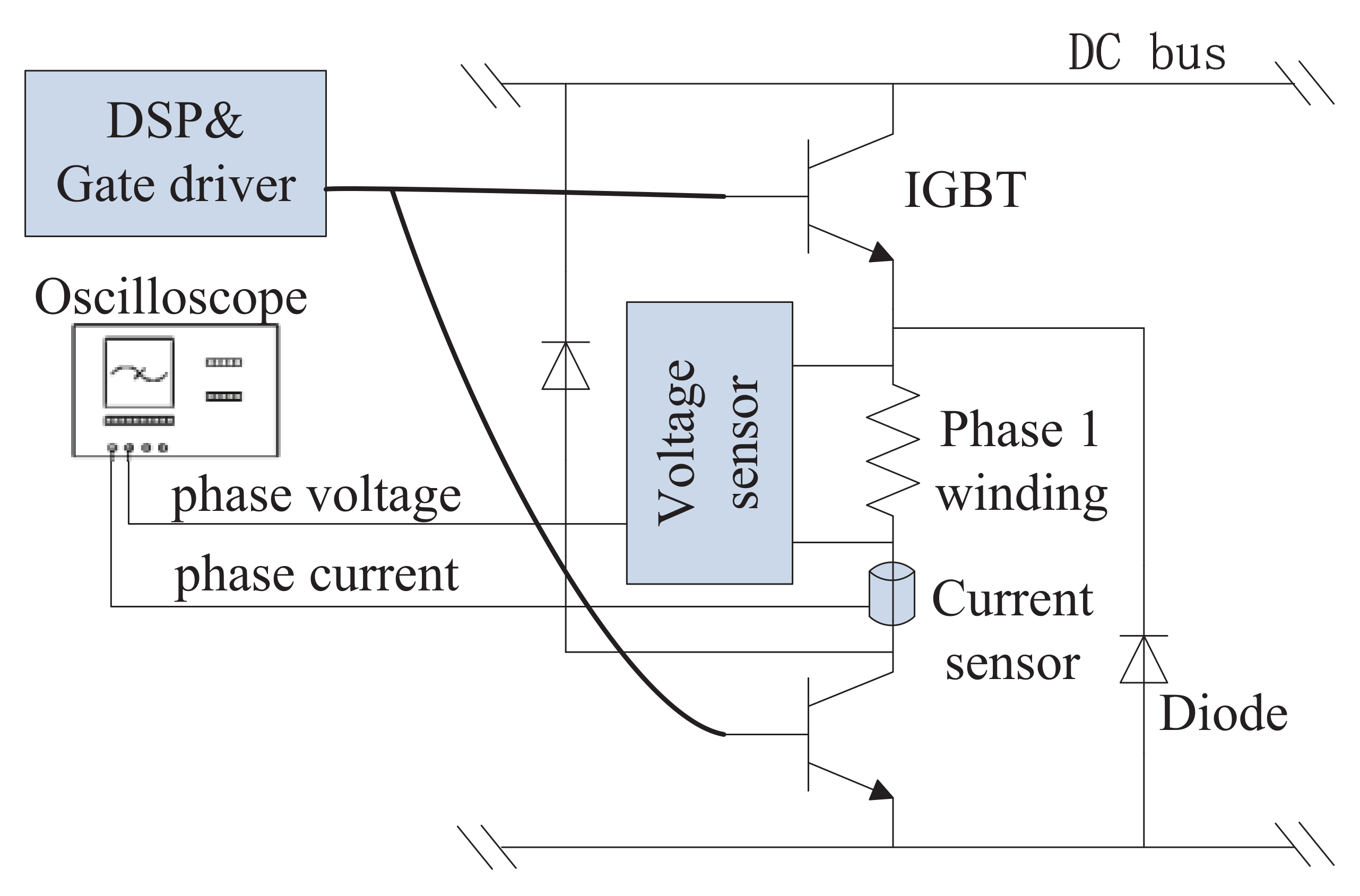
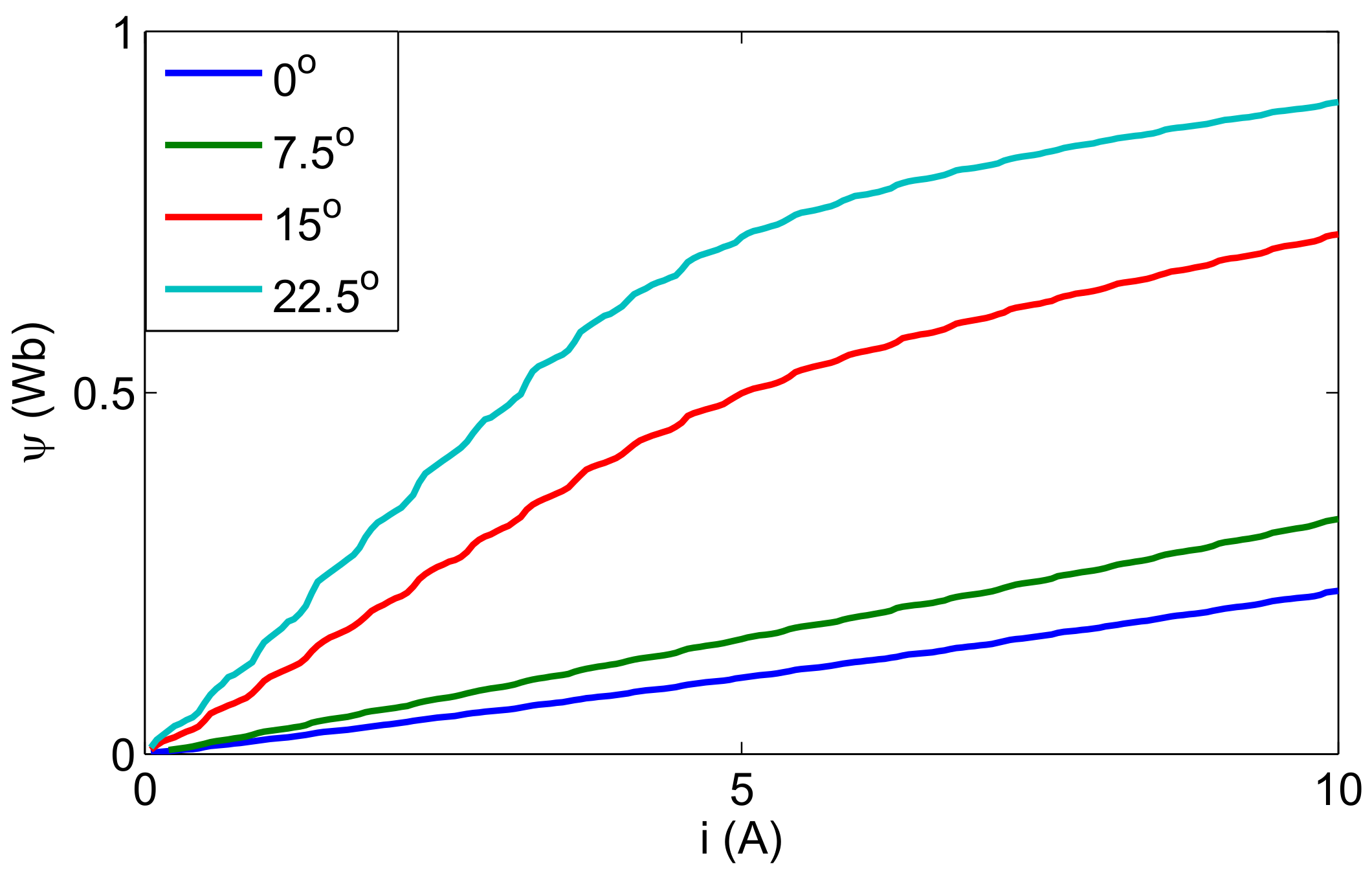
2. Measurement of Flux-Linkage Characteristics

A practical measuring method is developed to obtain the flux-linkage curves of a three-phase 12/8-pole SRM in [21]. One of the most important features of this method is that no locking device is adopted in the test. As analyzed in [21], there are special rotor positions where the torque is zero, named equilibrium positions. For a three-phase 12/8 pole SRM, there are four equilibrium positions, as shown in Figure 1. Firstly, these equilibrium positions can be found by exciting different phases. Then, the pulsed DC voltage is applied to the corresponding phase. Meanwhile, the phase voltage and current waveforms are stored to calculate the flux-linkage values at these special rotor positions. This measuring method is adopted in this paper.
The flux-linkage measurement circuit is shown in Figure 2. A three-Phase 1.5-kW 12/8 SRM is used in the test. The phase current and phase voltage are measured with current and voltage sensors and then recorded in the digital oscilloscope for further processing in MATLAB software. The measurement steps are summarized as follows.
(1)
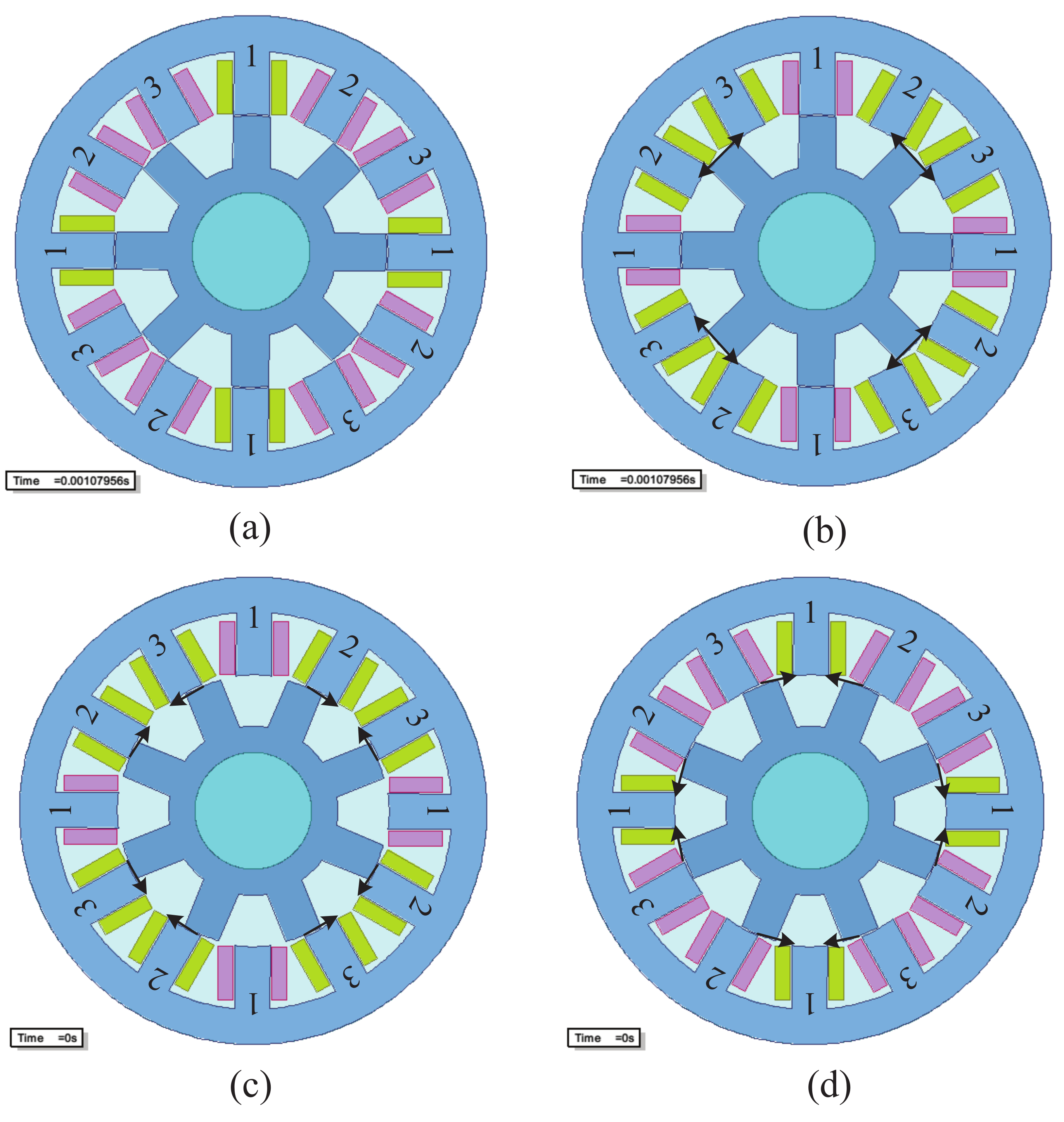
Exciting Phase 1, the rotor will be attracted to the aligned position of the stator and rotor, and this position is defined as 22.5°.
(2)
The oscilloscope records the current waveforms of the voltage and current of Phase 1.
(3)
Exciting both Phases 2 and 3 at the aligned position of Phase 1, the rotor will continue to remain in standstill at 22.5°.
(4)
The oscilloscope records the current waveforms of the voltage and current of Phase 2.
(5)
Exciting Phase 2, the rotor will be attracted to the aligned position of Phase 2.
(6)
Exciting Phases 2 and 3 simultaneously by the same voltage, the rotor will be in standstill at 0°.
(7)
The oscilloscope records the current waveforms of the voltage and current of Phase 3.
(8)
Exciting Phase 1 by a pulsed voltage and exciting Phases 2 and 3 simultaneously by the same voltage to maintain the position.
(9)
The oscilloscope records the current waveforms of the voltage and current of Phase 1.
According to the measured phase voltage and current, the flux-linkage is calculated as follows:
ψ ( k ) θ = c o n s t = j = 1 k [ u ( j ) R s i ( j ) ] T s + ψ ( 0 )
where ψ ( k ) is the flux-linkage characteristic of the phase winding at a specific position θ . u, i and R s are phase voltage, phase current and stator phase resistance, respectively. k is the number of sampling points, and T s is the sampling period. ψ ( 0 ) is the initial value of flux-linkage of phase winding. Because there is no permanent magnet in SRM, the initial value of flux-linkage ψ ( 0 ) is zero.
Due to symmetry among the phases, the flux-linkage characteristics of different phases are the same, except for the phase shift, which is 15° for three-phase 12/8 pole SRM. Note that the definition of rotor position is for Phase 1. Therefore, the relationship among flux-linkage curves of three phases can be derived as:
ψ 2 ( 22.5 ° ) = ψ 1 ( 7.5 ° ) ψ 3 ( 0 ° ) = ψ 1 ( 15 ° )
Combining Equations (1) and (2), the flux-linkage characteristics of the considered SRM at 0°, 7.5°, 15° and 22.5° are obtained and shown in Figure 3.
It should be noted that more than one phase is excited at the same time for measurement of the flux-linkage curves at 0°, 7.5° and 15°, which will result in mutual inductance between the excited phases. Although the mutual inductance introduces some errors to the measurement results, its influence is limited when the excitation form NSNSNSNSNSNSis adopted [21]. In order to verify the measurement accuracy, the comparison of the flux-linkage curves at four special positions between the equilibrium position method and rotor clamping method is shown in Figure 4. It can be seen that the results of the equilibrium position method and the rotor clamping method match closely, so the results of the equilibrium position method can be used for the modeling of the flux-linkage characteristic.

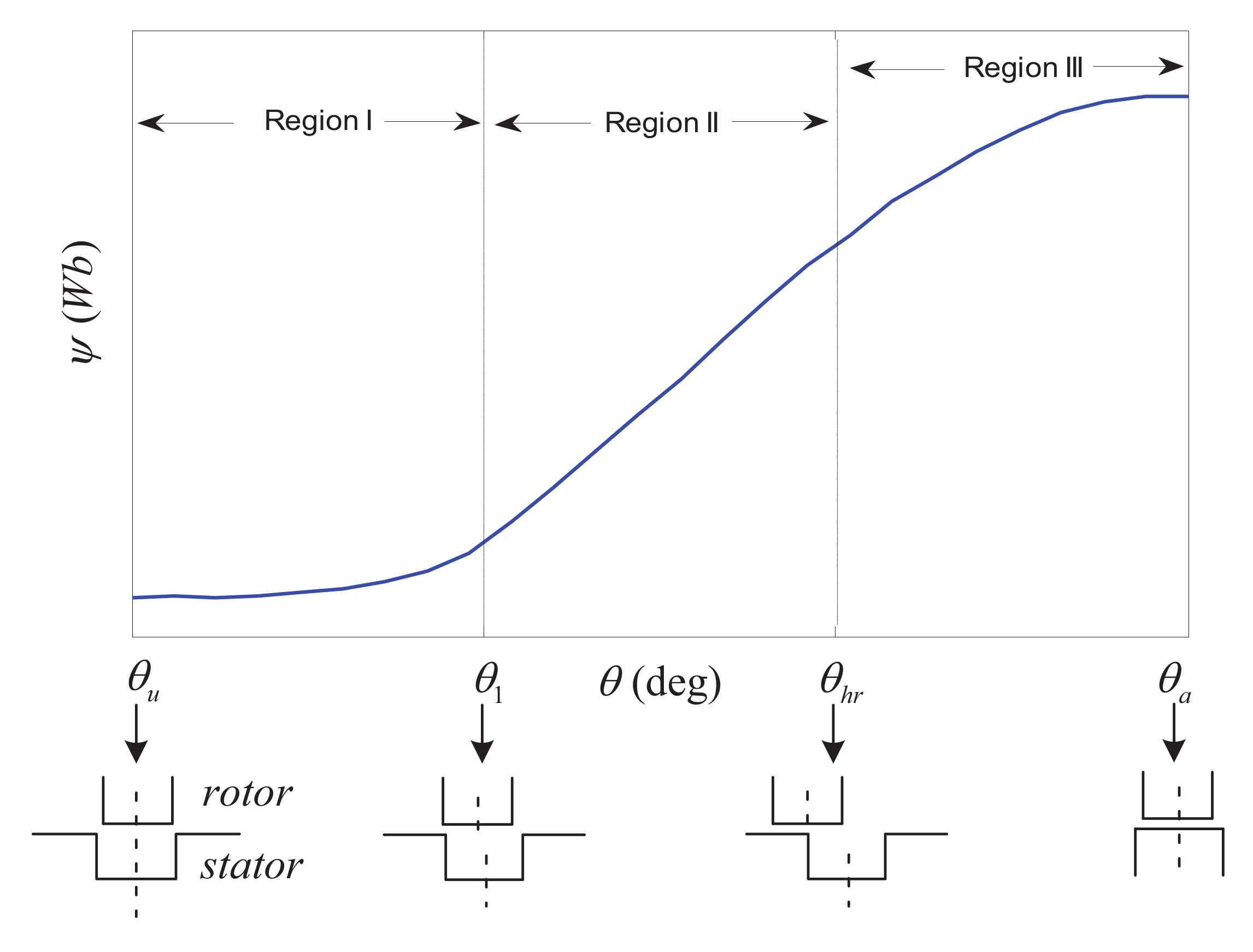
3. Modeling the Entire Flux-Linkage Characteristics

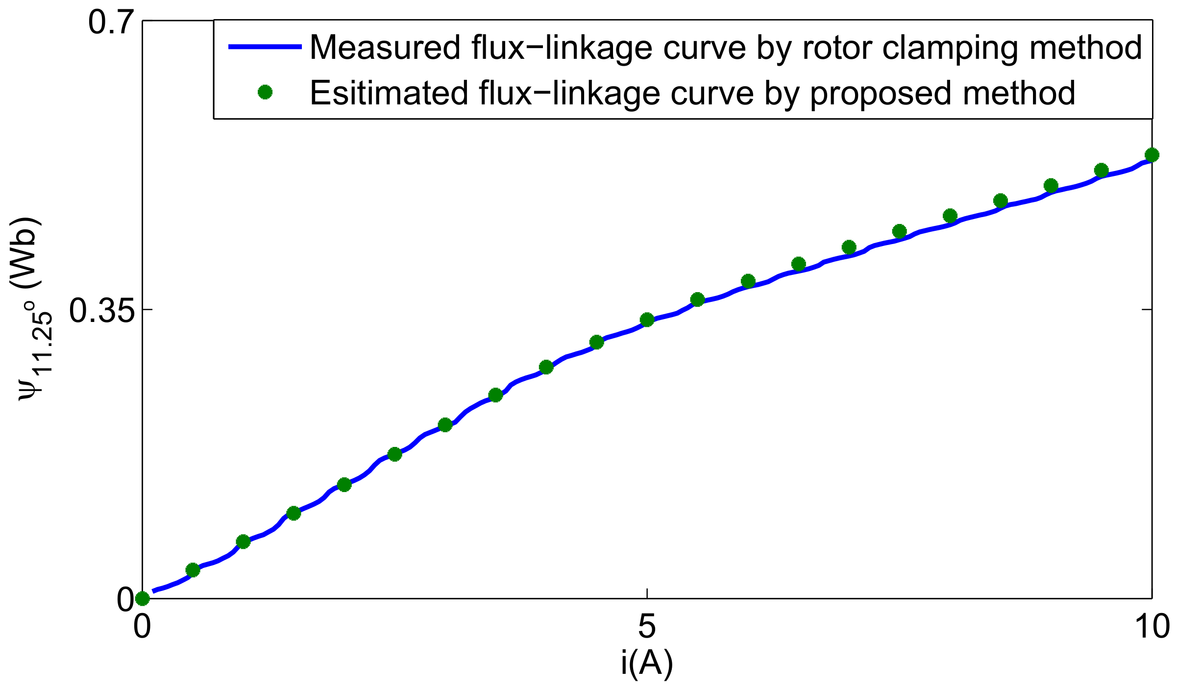
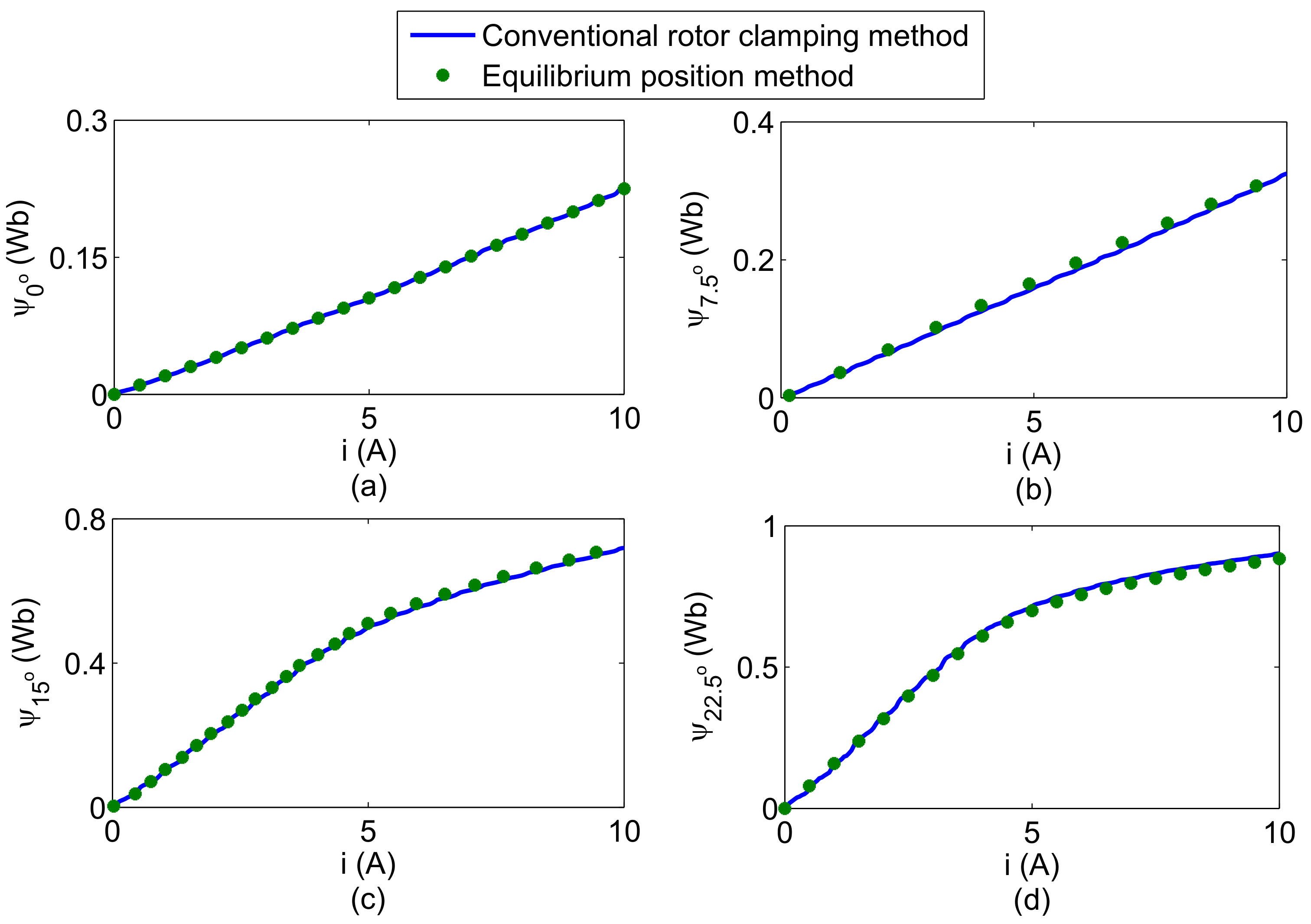
3.1. Solving the Flux-Linkage Curve at the Middle Position

Figure 5 shows the variation of flux-linkage with rotor position at specific current. In Figure 5, the flux-linkage curve can be divided into three regions, i.e., Region I [ θ u , θ 1 ), Region II [ θ 1 , θ h r ) and Region III [ θ h r , θ a ]. θ u represents the unaligned position, which is defined as 0° in this paper; θ 1 is the corner point, where the approaching corners of the stator and rotor poles are aligned; θ h r is a dividing point, where the approaching corner of the stator and center line of the rotor are aligned; θ a represents the aligned position, which is 22.5° in this paper. It can be seen from Figure 5 that the flux-linkage exhibits an approximately linear relationship with the position in Region II. Therefore, as long as [ 7.5 ° , 15 ° ] is included in [ θ 1 , θ h r ], the flux-linkage curve at the middle position can be calculated.
For SRM, the corner point θ 1 and the dividing point θ h r can be calculated as:
θ 1 = ( 360 ° N r β s β r ) / 2 θ h r = ( 360 ° N r β r ) / 2
where β s and β r are pole arc widths of the stator and rotor, respectively, which satisfy the following equation:
m i n ( β s , β r ) 360 ° q N r
where q is the number of phases of SRM and N r is the number of rotor poles of SRM. For three-phase 12/8 pole SRM, q = 3 and N r = 8. By substituting (4) into (3), we have:
θ 1 7.5 ° θ h r 15 °
Therefore, the flux-linkage-position characteristic ( ψ θ ) at [ 7.5 ° , 15 ° ] is approximately a linear relationship. Further, the flux-linkage curve of the middle position 11.25° can be calculated as:
ψ 11.25 ° ( i , θ ) = ψ 7.5 ° ( i , θ ) + ψ 15 ° ( i , θ ) 2
To evaluate the accuracy of the estimate result at middle position 11.25°, the comparison between the conventional rotor clamping method and the proposed method is carried out and shown as in Figure 6. It can be noticed that there are still small differences between the estimated and the measured results, but the accuracy is good enough. Therefore, in the next subsection, the entire electromagnetic characteristics of the SRM will be modeled based on the four measured and one estimated flux-linkage curves.

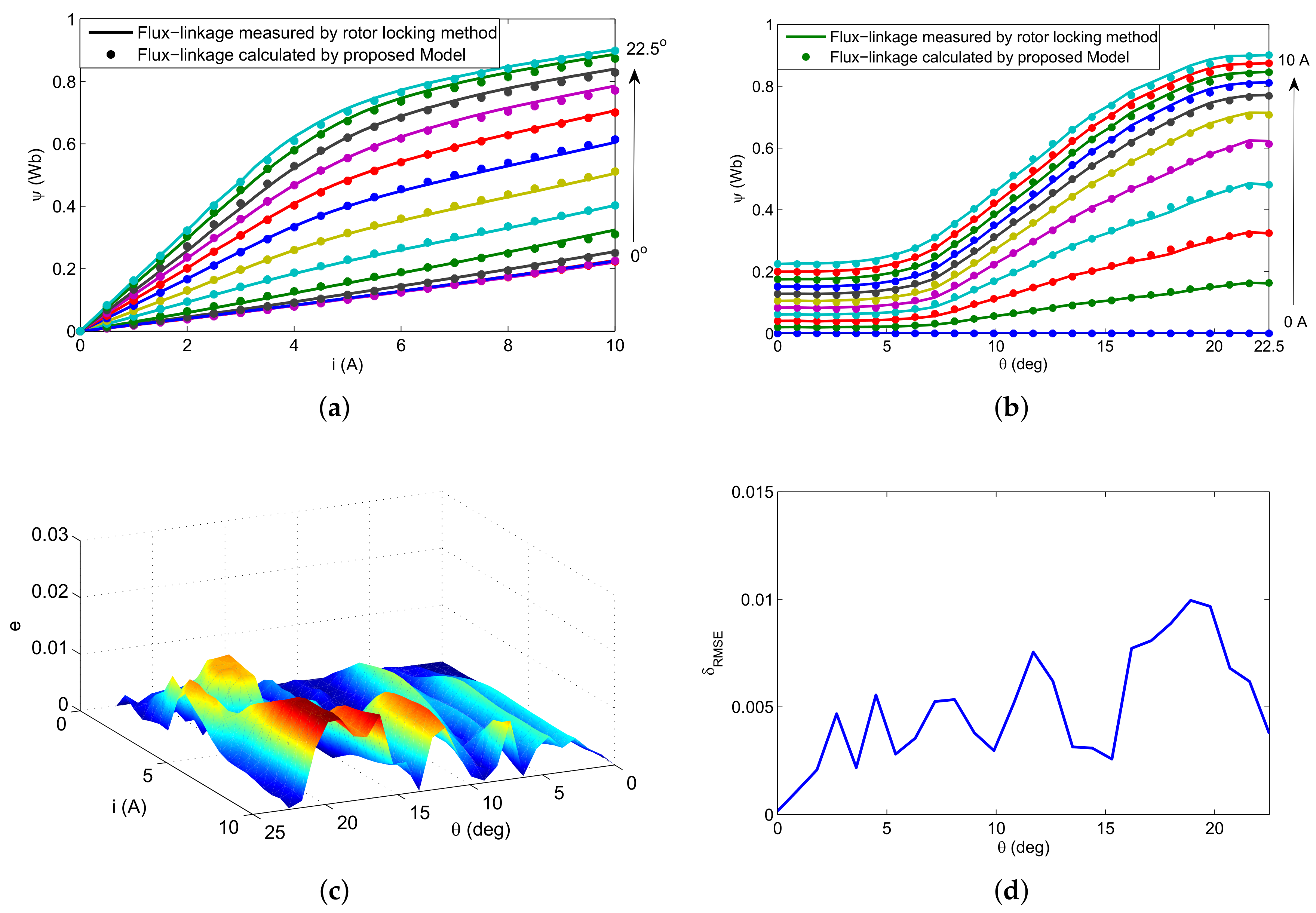
3.2. Five-Order Fourier Series Flux-Linkage Model

The stator phase inductance of the SRM can be modeled by the following Fourier series [22]:
L ( i , θ ) = n = 0 L n ( i ) c o s ( n N r θ )
By multiplying Equation (7) with the phase current i, the flux-linkage expression can be derived as follows:
ψ ( i , θ ) = n = 0 i L n ( i ) c o s ( n N r θ ) = n = 0 λ n ( i ) c o s ( n N r θ )
where λ n ( i ) is the coefficient, which can be calculated based on the flux-linkage curves of different positions.
Based on the five flux-linkage curves at specific positions, Equation (8) can be simplified as a five-order Fourier series:
ψ ( i , θ ) = λ 0 ( i ) + λ 1 ( i ) c o s ( N r θ ) + λ 2 ( i ) c o s ( 2 N r θ ) + λ 3 ( i ) c o s ( 3 N r θ ) + λ 4 ( i ) c o s ( 4 N r θ )
Obviously, only to determine the Fourier series coefficients λ 0 ( i ) , λ 1 ( i ) , λ 2 ( i ) , λ 3 ( i ) and λ 4 ( i ) , the entire flux-linkage characteristics of SRM can be obtained. Using (9), the flux-linkage curves of five special positions are described as follows:
Ψ 5 × 1 = M 5 × 5 Λ 5 × 1
where Ψ 5 × 1 = [ ψ 0 ( i ) ψ 7.5 ( i ) ψ 11.25 ( i ) ψ 15 ( i ) ψ 22.5 ( i ) ] T , Λ 5 × 1 = [ λ 0 ( i ) λ 1 ( i ) λ 2 ( i ) λ 3 ( i ) λ 4 ( i ) ] T , M 5 × 5 = :
1 1 1 1 1 1 c o s ( π / 3 ) c o s ( 2 π / 3 ) c o s ( π ) c o s ( 4 π / 3 ) 1 c o s ( π / 2 ) c o s ( π ) c o s ( 3 π / 2 ) c o s ( 2 π ) 1 c o s ( 2 π / 3 ) c o s ( 4 π / 3 ) c o s ( 2 π ) c o s ( 8 π / 3 ) 1 c o s ( π ) c o s ( 2 π ) c o s ( 3 π ) c o s ( 4 π ) .
Meanwhile, a high order polynomial with a constant term of zero is used to fit the flux-linkage curves of the above five special positions:
Ψ 5 × 1 = A 5 × 7 I 7 × 1
where I 7 × 1 = [ i i 2 i 3 i 4 i 5 i 6 i 7 ] T and the coefficient matrix A 5 × 7 is determined by the least square method, as shown in Table 1.
According to Equations (10) and (11), the Fourier series coefficient matrix can be calculated as follows:
Λ 5 × 1 = M 5 × 5 1 A 5 × 7 I 7 × 1
To demonstrate the accuracy of the modeling, comparative studies are carried out between the proposed analytical method and the rotor clamping method. The comparison results of the characteristics between the flux-linkage with current and flux-linkage with rotor position are shown in Figure 7a,b, respectively. There was a good agreement between the calculated and measured flux-linkages.
To quantify the accuracy of the proposed analytical calculation method, the performance index is presented in Figure 7c,d and defied as follows:
e = | ψ c a l c u l a t e d ψ m e a s u r e d | δ R M S E = 1 N j = 1 N e 2 ( j )
where N is the number of samples of the current.
It can be observed from Figure 7b,c that the errors in [ 15 ° , 22.5 ° ] between the calculated and measured method are relatively large. However, the errors for all of the rotor positions are less than 0.01. The results show that the calculated and measured flux-linkages agree well, which verifies the accuracy and effectiveness of the proposed analytical method.

3.3. Electromagnetic Torque Characteristics

The electromagnetic torque of a phase in SRM can be obtained using:
T = W c ( θ , i ) θ i = c o n s t = 0 i ψ ( θ , i ) d i θ i = c o n s t
where T is the phase torque and W c is the co-energy.
It should be noted that i and θ are decoupled in the proposed method, which makes the differential more convenient. Substituting (9) into (14) yields:
T = θ 0 i [ λ 0 ( i ) + λ 1 ( i ) c o s ( N r θ ) + λ 2 ( i ) c o s ( 2 N r θ ) + λ 3 ( i ) c o s ( 3 N r θ ) + λ 4 ( i ) c o s ( 4 N r θ ) ] d i i = c o n s t = N r s i n ( N r θ ) 0 i λ 1 ( i ) d i 2 N r s i n ( 2 N r θ ) 0 i λ 2 ( i ) d i 3 N r s i n ( 3 N r θ ) 0 i λ 3 ( i ) d i 4 N r s i n ( 4 N r θ ) 0 i λ 4 ( i ) d i
Combining Equations (12) and (15), the torque characteristic can be calculated.

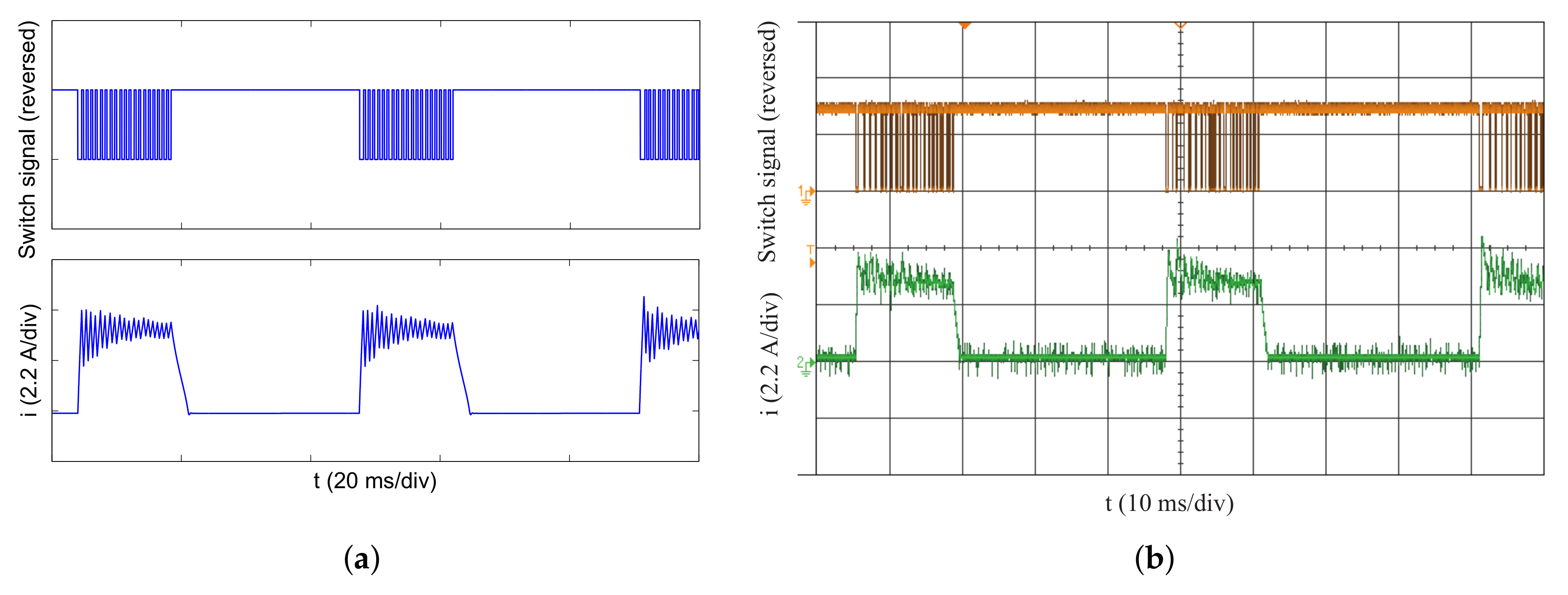
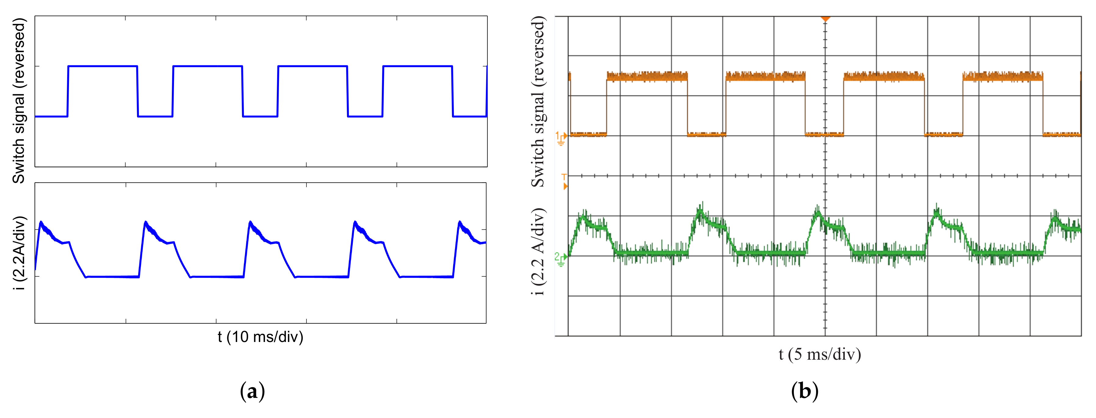
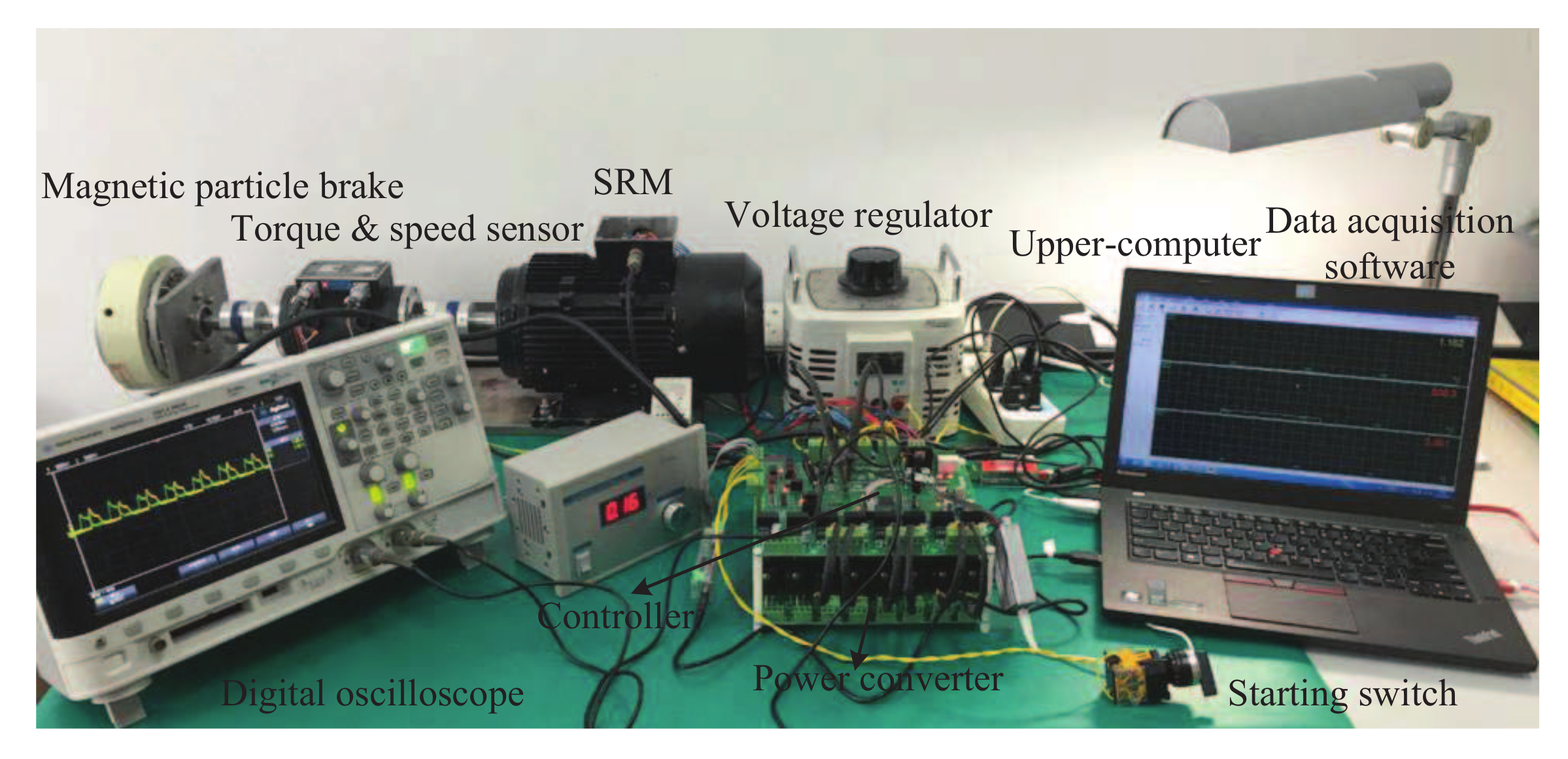
4. Dynamic Simulation and Experiment

In this section, to further verify the effectiveness of the proposed modeling method, the comparison studies between the simulation and experiment are carried out by using a three-phase 12/8 pole 1.5-kW SRM. The details of the motor parameters are listed in Table 2.

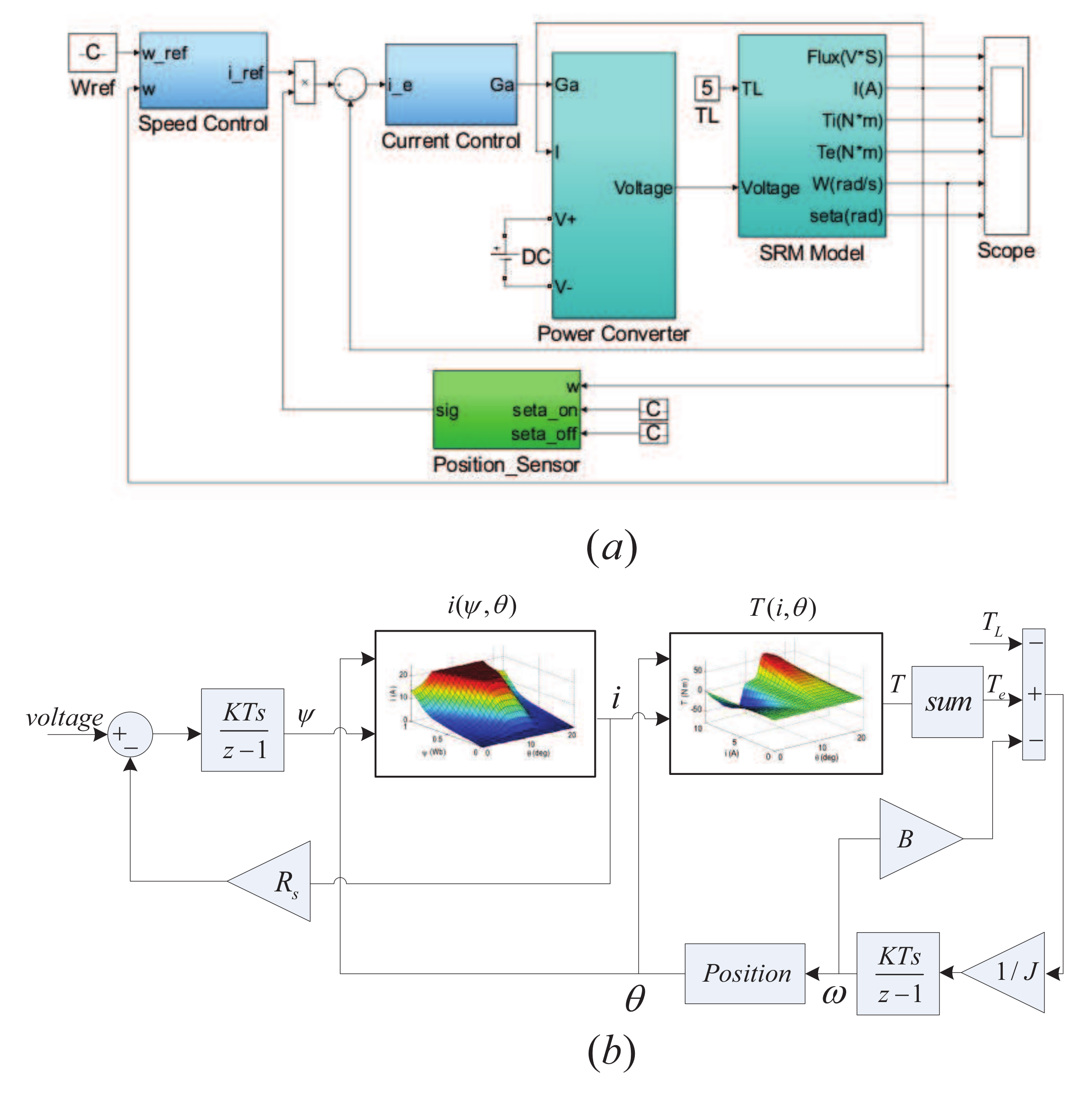
4.1. Dynamic Simulation Model

In order to simulate the actual SRM dynamics, a system simulation model is shown in Figure 8a, which is set up in MATLAB/Simulink software. The proportional-integral (PI) controller is used to regulate the speed of the SRM. Its parameters k p and k i are set to 0.1 and 0.05, respectively. The sampling frequencies of the speed loop and current loop in the simulation are set as 1 kHz and 10 kHz, respectively. In Figure 8b, T L is the load torque, ω is the rotor speed, T e is the total electromagnetic torque, J is the moment of inertia and B is the friction coefficient. As can be seen from Figure 8b, two look-up tables including current-flux-position i ( ψ , θ ) characteristics and torque-current-position T ( i , θ ) characteristics are used to build the SRM model, which are obtained by Equations (9) and (15). Two operation modes, which included current chopping control (CCC) and pulse width modulation (PWM), were simulated to test the accuracy of the proposed analytical method. The simulation results are presented in Figure 9a and Figure 10a.

4.2. Results Comparison

A SRM test bench is built to compare with the simulation results, as shown in Figure 11. Two experiments that keep the same conditions (i.e., using the same sampling frequency, operation mode, speed, load and turn-on and turn-off angle) as the simulation were implemented. The experiment results are shown in Figure 9b and Figure 10b.
Figure 9a,b exhibits a comparison between the simulation and experiment waveforms of the phase switching signal and phase current. The speed reference and load torque in this study are 180 r/min and 4.0 Nm, respectively. At this operation point, the average switching frequency is about 1129 Hz, and the peak current is around 5.6 A. As shown in Figure 9a,b, a good agreement can be found.
In addition, except the CCC operation, the dynamic simulation model can be also tested for voltage PWM mode. Figure 10a,b shows the simulation and experiment waveforms of the phase switching signal and phase current at the test condition of speed reference 650 r/min and load torque 1.5 Nm. The switching frequency and peak current are 10 kHz and 2.7 A, respectively. These waveforms indicate that the simulation and experiment results are in good agreement.
Through the above comparison and analysis, the effectiveness of the proposed modeling method is demonstrated. However, in order to further quantitatively compare the simulation and experimental results, the relative error σ is defined as follows:
σ = | i e i s | | i e | × 100 %
where i e and i s represent the experimental and simulated current values, respectively. It can be calculated that the relative error σ between the simulation and experiment results is less than 15% in both the current chopping and voltage PWM operations. The deviations between the results from the simulation and experiment are mainly caused by the modeling errors of the flux-linkage, phase resistance variation and measurement process. Besides, the influence of eddy current and magnetic hysteresis is ignored in the simulation, which will also lead to the difference between the simulation and experimental waveforms in some regions. In sum, the proposed modeling method has a satisfactory performance and can be used for SRM performance prediction and advanced control, but in the future, it is still necessary to further improve its accuracy.

5. Conclusions

An accurate method for modeling the electromagnetic characteristics of SRM is proposed in this paper. The flux-current ( ψ i ) characteristics of five special positions are obtained by combining the measurement technique of the equilibrium position and the estimation method of flux-linkage in the middle position. The analytical model of flux-linkage that decouples the phase current and rotor position is built based on five-order Fourier series expansion. Once the coefficients of the Fourier series expansion are determined by five special flux-linkage curves, all the electromagnetic characteristics can be obtained easily. The comparative study shows that the calculated electromagnetic characteristics from the proposed method are in good agreement with the measured electromagnetic characteristics by the conventional rotor clamping method. Finally, the dynamic simulation model of the SRM prototype is constructed based on the calculated electromagnetic characteristics. The accuracy of the proposed method is further verified by the comparison between the simulation and experiment results.

Acknowledgments

This work was supported in part by the National Natural Science Foundation of China (No. 51609033) and in part by the Fundamental Research Funds for the Central Universities (Nos. 3132017133 and 3132017130). The authors sincerely thank the reviewers for their valuable comments, which improved the quality of the paper.

Author Contributions

Cunhe Li and Guofeng Wang proposed the modeling method and wrote the manuscript. Jian Liu carried out the simulation analysis for the method. Yan Li and Yunsheng Fan performed the experiments and edited the manuscript.

Conflicts of Interest

The authors declare no conflict of interest.

References

  1. Kiyota, K.; Sugimoto, H.; Chiba, A. Comparing electric motors: An analysis using four standard driving schedules. IEEE Ind. Appl. Mag. 2014, 20, 12–20. [Google Scholar] [CrossRef]
  2. Miller, T. Optimal design of switched reluctance motors. IEEE Trans. Ind. Electron. 2002, 49, 15–27. [Google Scholar] [CrossRef]
  3. Bostanci, E.; Moallem, M.; Parsapour, A.; Fahimi, B. Opportunities and challenges of switched reluctance motor drives for electric propulsion: A comparative study. IEEE Ind. Appl. Mag. 2014, 20, 12–20. [Google Scholar] [CrossRef]
  4. Nezamabadi, M.M.; Afjei, E. Switched reluctance motor for hybrid motion control: Design, modelling, and sensorless drive. IET Electr. Power Appl. 2016, 10, 498–507. [Google Scholar] [CrossRef]
  5. Parreira, B.; Rafael, S.; Pires, A.J.; Branco, P.J.C. Obtaining the magnetic characteristics of an 8/6 switched reluctance machine: From FEM analysis to the experimental tests. IEEE Trans. Ind. Electron. 2005, 52, 1635–1643. [Google Scholar] [CrossRef]
  6. Song, S.; Ge, L.; Ma, S.; Zhang, M.; Wang, L. Accurate measurement and detailed evaluation of static electromagnetic characteristics of switched reluctance machines. IEEE Trans. Instrum. Meas. 2015, 64, 704–714. [Google Scholar] [CrossRef]
  7. Gobbi, R.; Sahoo, N.C.; Vejian, R. Experimental investigations on computer-based methods for determination of static electromagnetic characteristics of switched reluctance motors. IEEE Trans. Instrum. Meas. 2008, 57, 2196–2211. [Google Scholar] [CrossRef]
  8. Xue, X.D.; Cheng, K.W.E.; Ho, S.L. Simulation of switched reluctance motor drives using two-dimensional bicubic spline. IEEE Trans. Energy Convers. 2002, 17, 471–477. [Google Scholar] [CrossRef]
  9. Elmas, C.; Sagiroglu, S.; Colak, I.; Bal, G. Modelling of a nonlinear switched reluctance drive based on artificial neural network. In Proceedings of the Fifth International Conference on Power Electronics and Variable-Speed Drives, London, UK, 26–28 October 1994; pp. 7–12. [Google Scholar]
  10. Lu, W.; Keyhani, A.; Fardoun, A. Neural network-based modeling and parameters identification of switched reluctance motors. IEEE Trans. Energy Convers. 2003, 18, 284–290. [Google Scholar]
  11. Zhong, R.; Xu, Y.; Cao, Y.; Guo, X.; Hua, W.; Xu, S.; Sun, W. Accurate model of switched reluctance motor based on indirect measurement method and least square support vector machine. IET Electr. Power Appl. 2016, 10, 916–922. [Google Scholar] [CrossRef]
  12. Chen, H.; Han, G.; Yan, W.; Lu, S.; Chen, Z. Modeling of a switched reluctance motor under stator winding fault condition. IEEE Trans. Appl. Supercond. 2016, 26. [Google Scholar] [CrossRef]
  13. Liang, D.; Ding, W. Modelling and predicting of a switched reluctance motor drive using radial basis function network-based adaptive fuzzy system. IET Electr. Power Appl. 2008, 3, 218–230. [Google Scholar] [CrossRef]
  14. Lachman, T.; Mohamad, T.R.; Fong, C.H. Nonlinear modelling of switching reluctance motors using artificial intelligence techniques. IET Electr. Power Appl. 2004, 151, 23–60. [Google Scholar]
  15. Hossain, S.A.; Husain, I. A geometry based simplified analytical model of switched reluctance machines for real-time controller implementation. IEEE Trans. Power Electron. 2003, 19, 1384–1389. [Google Scholar] [CrossRef]
  16. Bernat, J.; Stepien, S.; Sykulski, J.K. Determining Switched Reluctance Motor Current Waveforms Exploiting the Transformation from the Time to the Position Domain. Energies 2017, 10, 799. [Google Scholar] [CrossRef]
  17. Tan, C.; Wang, H.; Chen, L. Analytical method for the prediction of natural frequencies of switched reluctance motor based on electromechanical analogy method. COMPEL Int. J. Comput. Math. Electr. Electron. Eng. 2018, 37, 224–241. [Google Scholar] [CrossRef]
  18. Khalil, A.; Husain, I. A fourier series generalized geometry-based analytical model of switched reluctance machines. IEEE Trans. Ind. Appl. 2007, 43, 673–684. [Google Scholar] [CrossRef]
  19. Song, S.; Zhang, M.; Ge, L. A new decoupled analytical modeling method for switched reluctance machine. IEEE Trans. Magn. 2015, 51. [Google Scholar] [CrossRef]
  20. Chi, H.P.; Lin, R.L.; Chen, J.F. Simplified flux-linkage model for switched-reluctance motors. IEE Proc. Electr. Power Appl. 2005, 152, 577–583. [Google Scholar] [CrossRef]
  21. Song, S.; Zhang, M.; Ge, L. A new fast method for obtaining flux-linage characteristics of SRM. IEEE Trans. Ind. Electron. 2015, 62, 4105–4117. [Google Scholar] [CrossRef]
  22. Fahimi, B.; Suresh, G.; Mahdavi, J.; Ehsani, M. A new approach to model switched reluctance motor drive application to dynamic performance prediction, control and design. In Proceedings of the 29th Annual IEEE Power Electronics Specialists Conference, Fukuoka, Japan, 22 May 1998; pp. 2097–2102. [Google Scholar]
Figure 1. Cross-sectional view of the SRM with different rotor positions and excitation modes. (a) Exciting Phase 1 at 22.5°; (b) exciting Phases 2 and 3 at 22.5°; (c) exciting Phases 2 and 3 at 0°; (d) exciting Phase 1 at 0°.
Applsci 08 00537 g001
Figure 2. Flux-linkage measurement circuit.
Applsci 08 00537 g002
Figure 3. Measured flux-linkage curves by the equilibrium position method.
Applsci 08 00537 g003
Figure 4. Comparison of flux-linkage curves from the equilibrium position method and rotor clamping method. (a) 0°; (b) 7.5°; (c) 15°; (d) 22.5°.
Applsci 08 00537 g004
Figure 5. The variation of the flux-linkage with rotor position.
Applsci 08 00537 g005
Figure 6. Comparison of the estimated and measured flux-linkage curves at 11.25°.
Applsci 08 00537 g006
Figure 7. Entire flux-linkage characteristics. (a) Comparison of calculated and measured flux-current ( ψ - i) characteristics; (b) comparison of calculated and measured flux-position ( ψ - θ ) characteristics; (c) error between the calculated and measured flux-linkage; (d) root-mean-square error (RMSE).
Applsci 08 00537 g007
Figure 8. Simulation model of the SRM drive system. (a) System model; (b) SRM model for one phase.
Applsci 08 00537 g008
Figure 9. Switching signal and phase current with the current chopping control (CCC) mode. (a) Simulation; (b) experiment.
Applsci 08 00537 g009
Figure 10. Switching signal and phase current with the PWM mode. (a) Simulation; (b) experiment.
Applsci 08 00537 g010
Figure 11. Test bench.
Applsci 08 00537 g011
Table 1. Polynomial coefficients of the flux-linkage characteristic curves on five special positions.
a1a2a3a4a5a6a7
ψ 0 2.0721 × 10⁻²−9.3272 × 10−45.8819 × 10−4−1.4294 × 10−41.8268 × 10−5−1.1749 × 10−63.0049 × 10−8
ψ 7.5 3.3840 × 10⁻²−1.6889 × 10−44.0050 × 10−4−1.5927 × 10−42.4348 × 10−5−1.6901 × 10−64.4997 × 10−8
ψ 11.25 7.5204 × 10⁻²−1.1415 × 10−27.7113 × 10−3−2.1972 × 10−32.8990 × 10−4−1.8323 × 10−54.5204 × 10−7
ψ 15 1.0796 × 10⁻¹−1.1565 × 10−21.0335 × 10−2−3.2401 × 10−34.3797 × 10−4−2.7691 × 10−56.7627 × 10−7
ψ 22.5 1.7879 × 10⁻¹−3.1390 × 10−22.1949 × 10−2−6.9017 × 10−39.7977 × 10−4−6.5724 × 10−51.7067 × 10−6
Table 2. Specifications of the switched reluctance motor (SRM).
ParameterValue
Phase3
Stator/rotor poles12/8
Rated power1.5 kW
Rated torque9.55 N·m
Speed range of constant torque100–1500 r/min
Maximum flux linkage0.986 Wb
Stator resistance0.9 Ω
Moment of inertia0.01 kg·m2
Friction coefficient0.005 N·m·s
Aligned inductance154 mH
Unaligned inductance23 mH

