1. Introduction
According to the latest United Nations Population Division projections, the number of people on the planet exceeded 7.3 billion as of mid-2015 and it is expected to reach 9.7 billion in 2050 and 11.2 billion by 2100. In the next 15 years, 60% of the total population will be city dwellers. This number will increase to 70% by 2050 [
1]. These results show that the population is not only increasing, but is becoming progressively concentrated in urban areas as well. In this context, public transportation will remain to be an indispensable answer to the nation’s economic, energy, and environmental questions. As a result, local communities are expanding public transportation networks and people are using public transportation in increasing numbers.
Urban rail is the most rational solution for public transportation because it is well placed at the core of already existing public transportation networks given its high capacity, safety, and reliability [
2]. In order to improve usage of urban rail, some precautions, especially safety precautions must be taken. According to the statistics reported by Mu et al. [
3], 95% of traffic accident are related to human factors. Furthermore, 70% of these are directly related to human errors.
There are various studies for detecting obstacles, which compare the advantages and disadvantages of different technologies. These technologies have been studied using different sensors, like laser scanners [
4,
5,
6,
7,
8], radars [
9,
10,
11,
12], and computer vision [
13,
14,
15,
16]. Sensory fusions of the aforementioned sensors have also been studied for obtaining additional information, like laser scanner and radar fusion [
17], laser scanner and computer vision fusion [
18,
19,
20,
21], radar and computer vision fusion [
22,
23,
24], and the fusion of all three sensors [
25,
26]. Apart from these methods, digital mapping has been studied as a supplementary sensor based method for getting extra information obtained by the vehicle environment system [
27].
Computer vision-based obstacle detection methods are divided into three categories. The first one is the knowledge-based approach, which uses prior knowledge of obstacle features, like color [
28], symmetry [
29], and shadow [
30]. The second one is the stereo vision-based approach [
31] and the last one is the motion-based approach [
32]. Using computer vision to solve the problem of obstacle detection seems to be a rational solution at first. Although computer vision methods have advantages, such as lower cost sensors, higher information capacity, and lower operating power, all three methods fail in cases of complex shadows, complex illumination, and challenging weather conditions, like heavy rain, snow, and turbid fog. Additionally, this method needs high computational costs. All of these disadvantages put active sensors, like laser scanners and radars, to the forefront. In many applications, laser scanners and radar sensors have similar performances.
Radar sensors can be separated broadly into two categories depending on the application. The first one is 77 GHz long-range radars (LRR) [
33]. LRR can measure a 200 m distance like some laser scanner sensors. The second one is 24 GHz short-range radars (SRR) [
34]. SRR generally operates at a shorter distance in comparison to LRR. Although radar-based methods are better in terms of detection range and reliability rate in adverse weather conditions, they have a relatively low angular resolution of 15° [
35]. Thus, it is hard to detect multiple obstacles in crowded road conditions. To overcome this problem, multiple sensors need to be utilized. This makes the system more complicated.
Laser scanners are widely used for many applications from bar-code reading to vibration assessment [
36,
37]. Unlike video cameras, laser scanners offer accurate distances of up to 200 m. Moreover, these devices signals cannot easily interfere with other lighting sources by means of sending signals from their own signal sources.
Using a laser scanner to detect obstacles presents some difficulty, especially in varying weather conditions. Under conditions of fog, rain, and heavy snow, particles can cause the attenuation of signals or false echoes. The solution of these kinds of problems has been improved with multilayer laser scan planes by latter technology of laser scanners [
7].
In order to reduce human-induced road accidents, this study presents a collision avoidance system (CAS) based on an approach using a state-of-the-art multilayer laser scanner mounted in front of tram. The system is designed to detect all objects (static and moving) within a 110-degree field in the front of the tram. The aim of the system is to work in all the heavy traffic scenarios. The system that uses a laser scanner sensor was first used in real-time tests for trams.
This system is integrated to a Light Rail Vehicle (LRV) called “Silkworm”, which is manufactured by Durmazlar Machine Inc. (Bursa, Turkey) and tested on trams at facilities of Durmazlar Machine Inc.
2. System Overview
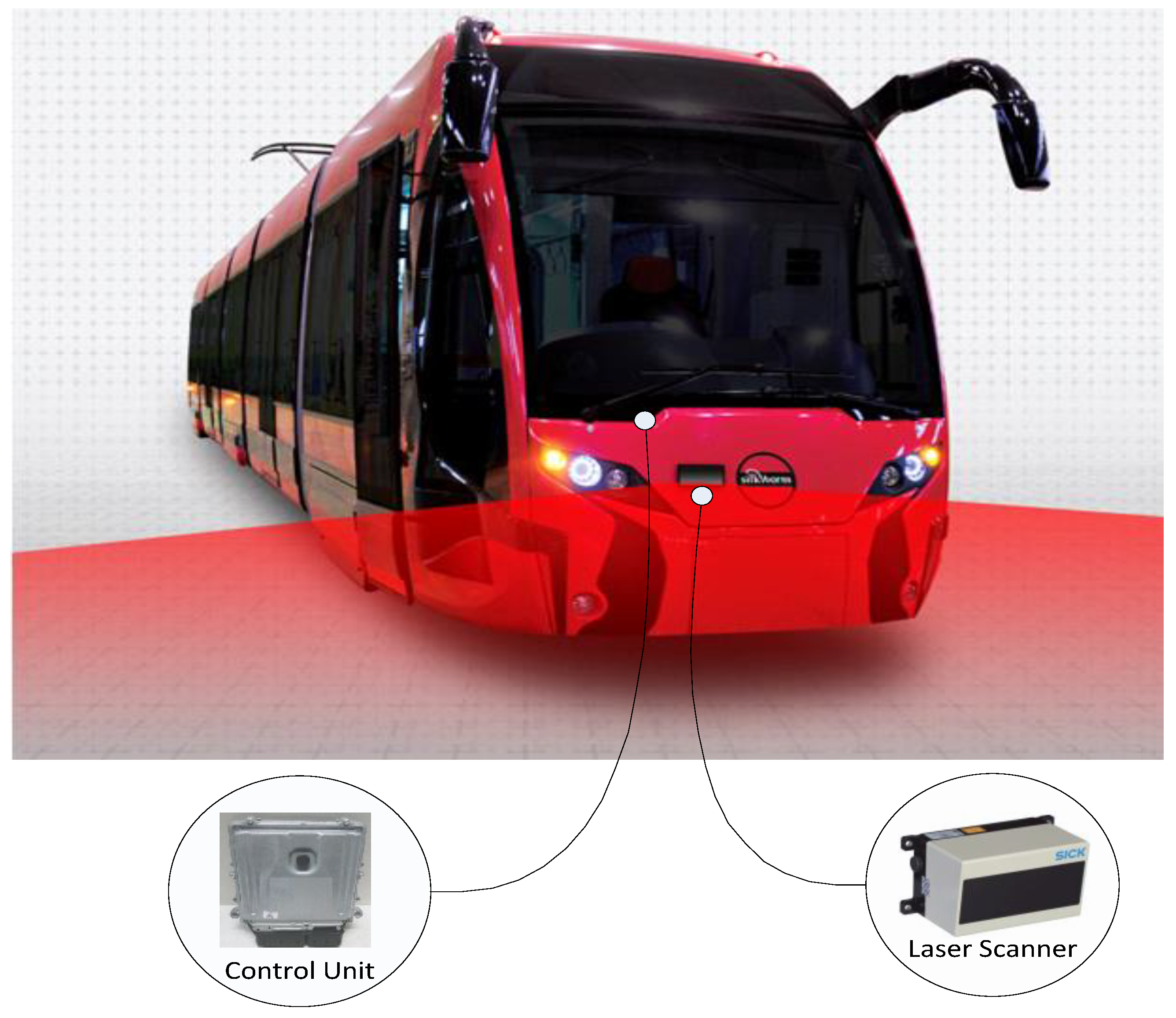
Every second of traveling around the city requires complete concentration for tram drivers as in the case of drivers of all vehicles. Traffic conditions might lead to undesirable results, like collisions with other trams, cars, trucks, and pedestrians at any time, especially in rush hours. In this study, a CAS, combining a laser scanner sensor and a rail control unit were developed and adapted to trams, as shown
Figure 1. The system not only warns a tram driver of an imminent possible danger of a crash, but it also activates the brakes and disengages the throttle to prevent collision in order to avoid unintended consequences. The CAS is engineered to work in all terrain and congestion scenarios. The system is the first step towards automated trams. System architecture and the laser scanner sensor are detailed as follows for the proposed CAS.
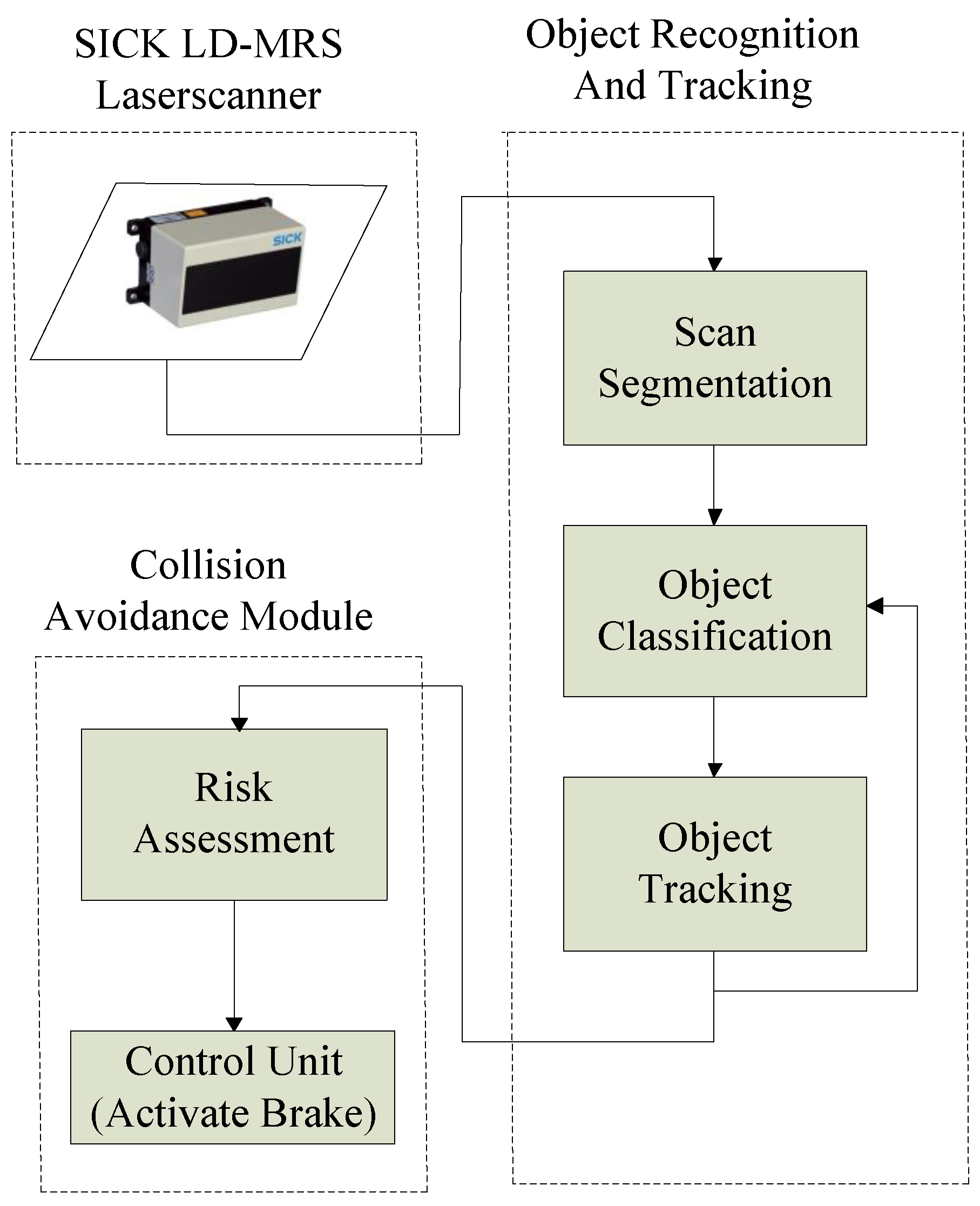
2.1. System Architecture
The system architecture for CAS is divided into three parts, as seen Figure 2. The laser scanner sensor provides raw data from the observed scene. Then, from the raw data, an object recognition algorithm is processed. The object recognition algorithm consists of three processes, called segmentation, classification, and tracking. Although the object recognition algorithm that is used in this phase can be sensitive to complicated road surroundings or measurement errors, which reduce the accuracy of the algorithm, this complexity cannot affect the algorithm much comparing to other road vehicles because trams cruise on fixed railways. The feedback loop between the classification and tracking processes is used to improve the performance of object recognition. In each scan of the laser scanner, positions of the objects in the scanned area are predicted and the classification parameters are updated.
After the object recognition algorithm, risk assessment is carried out. The system determines distance and calculates the likelihood of collision based on variables such as speed. It can detect objects within a 110-degree field in the front of the tram. If the CAS detects that an object is approaching dangerously close, then it activates a visual and acoustic warning for the driver. Should the tram driver not react to the warning signals within two seconds, the automated system slows the tram to a complete stop. According to Lee et al., the driver reaction time is approximately 1.195 s [
38]. If the driver does not respond in two seconds, it means that the driver does not notice the possible danger.
2.2. Sick Ladar DigitalMultilayer Range Scanner (LD-MRS) Laser Scanner
In this project, the Sick Ladar Digital-Multilayer Range Scanner (LD-MRS) laser scanner is utilized to detect obstacles in tramline. The laser scanner is mounted near the center of the frontal area of the test vehicle, named “Silkworm”, as seen in
Figure 1. The sensor can detect all objects in front of the vehicle up to 50 m with the accuracy of ±5 cm. The LD-MRS laser scanner has a variable scan area. In this study, the horizontal angle of visual field is limited to 110° from +50° to −60°. For obtaining simultaneous records of a scene, a video camera is mounted near the laser scanner sensor.
The LD-MRS is a four-layer laser scanner that uses Time-of-Flight (ToF) technology. It scans the surroundings radially with several rotating laser beams, receives the echoes with a photodiode receiver, and processes the data by means of a time of flight calculation. If the round trip time is
t, then the distance to the object is calculated as seen below:
where
d is the distance to the object and
c is the speed of light.
Multilayer laser scanner technology provides pitch angle compensation through four scan planes with various vertical angles. Thus, the sensor can detect all of the objects reliably, even while accelerating or breaking. Moreover, the LD-MRS has multi-echo capability. So, it can gather and evaluate up to three echoes per transmitted laser pulse. While the echo of a raindrop yields a very low voltage over a short period of time, the echo of an object yields a high voltage over a longer period. Therefore, a raindrop and an object can be distinguished easily.
3. Methods
According to the European Enhanced Vehicle Safety Committee, 2004 (EEVC WG 19) [
39] obstacle detection algorithms should be capable of the following,
Locating obstacles
Distinguishing obstacles (vehicles, pedestrians and others)
Tracking obstacles
Detecting potential hazards in order to eliminate false alarms
In designing a robust CAS, the accuracies of obstacle detection and tracking are the most powerful parameters because a possible error in these processes causes a failure of all the systems. This study uses the algorithm given in
Figure 2, to detect, classify, track, and assess the possible collision of obstacles in railways. The algorithm is utilized for detecting all static or moving obstacles, which are located in front of the tram. The algorithm processes are detailed as follows.
3.1. Segmentation
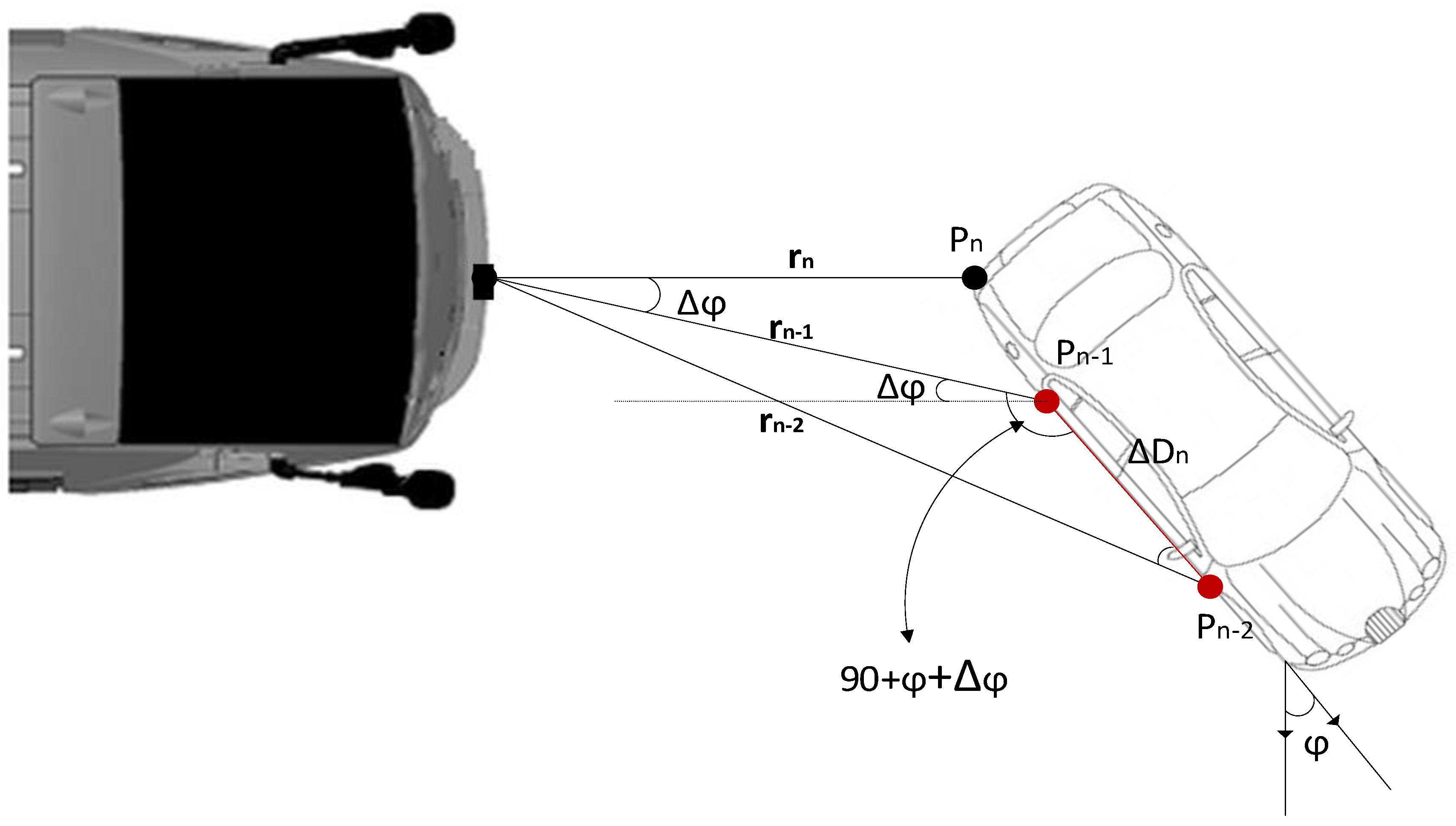
The segmentation phase is the first and the fundamental step of the object detection algorithm. The raw measurements that are provided by the laser scanner are separated into clusters that are supposed to belong to the same object. Among several segmentation processes, the Point Distance-Based method (PDBS) was selected for segmentation. Basically, if two consecutive scan points, Pn-1 and Pn-2, are not greater than the pre-defined threshold distance, they belong to the same object.
where D
thd is the threshold condition and
is the Euclidean distance between two consecutive detected points as shown in
Figure 3.
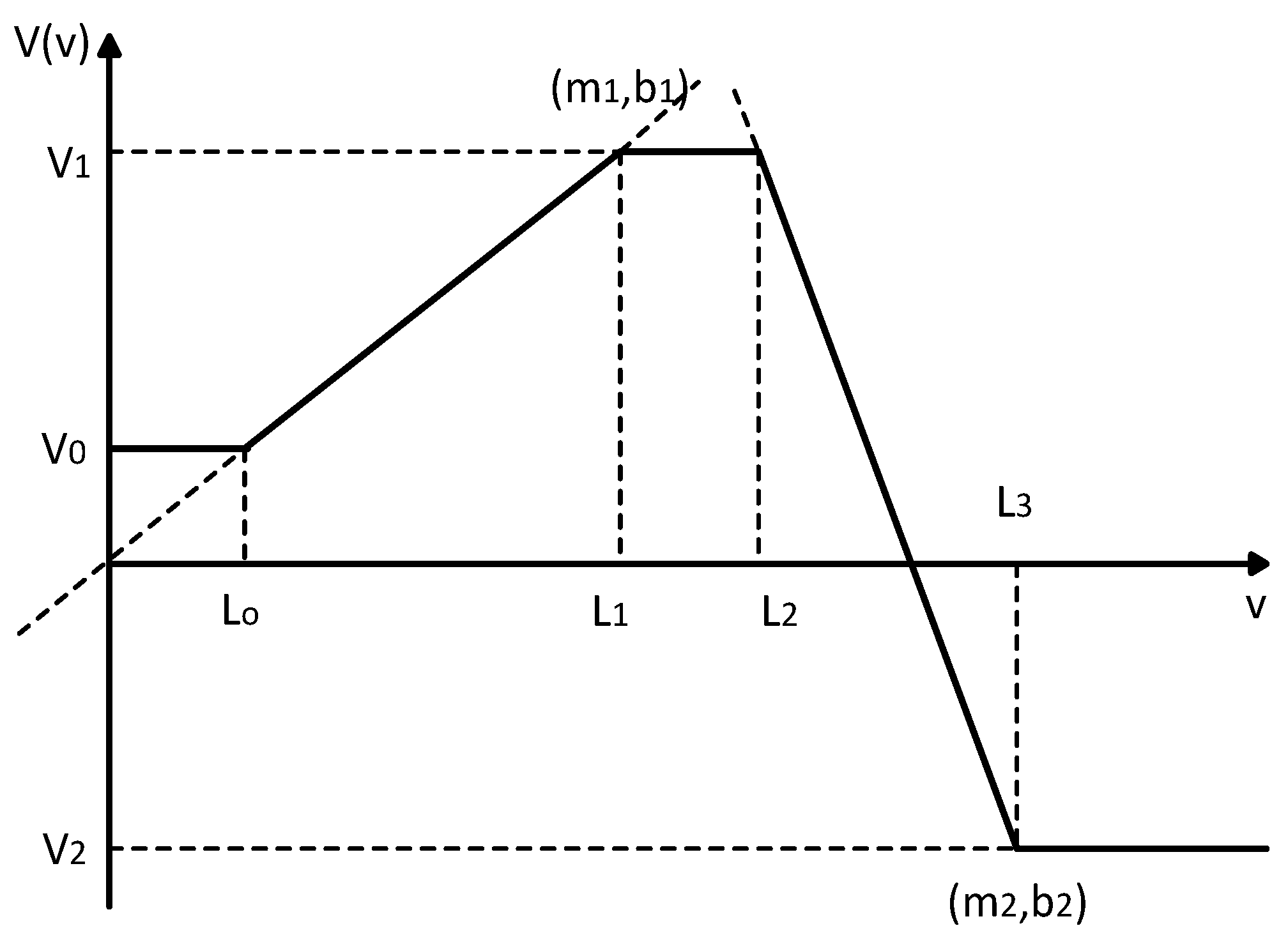
The performance of the segmentation phase is closely related to the selection of a threshold. There are several threshold methods. In [
40], the threshold is determined by:
where C
0. denotes the sensor noise and
denotes the angular resolution of the laser scanner.
Lee used another method shown below [
41]:
This study uses Adaptive Breakpoint Detector (ABD), which was proposed by [
42] for the threshold condition.
where λ is an auxiliary parameter and is chosen on user experience σ
r is a residual variance, including the stochastic behavior of the sequence of the detected points and related noise that is associated with r
n.
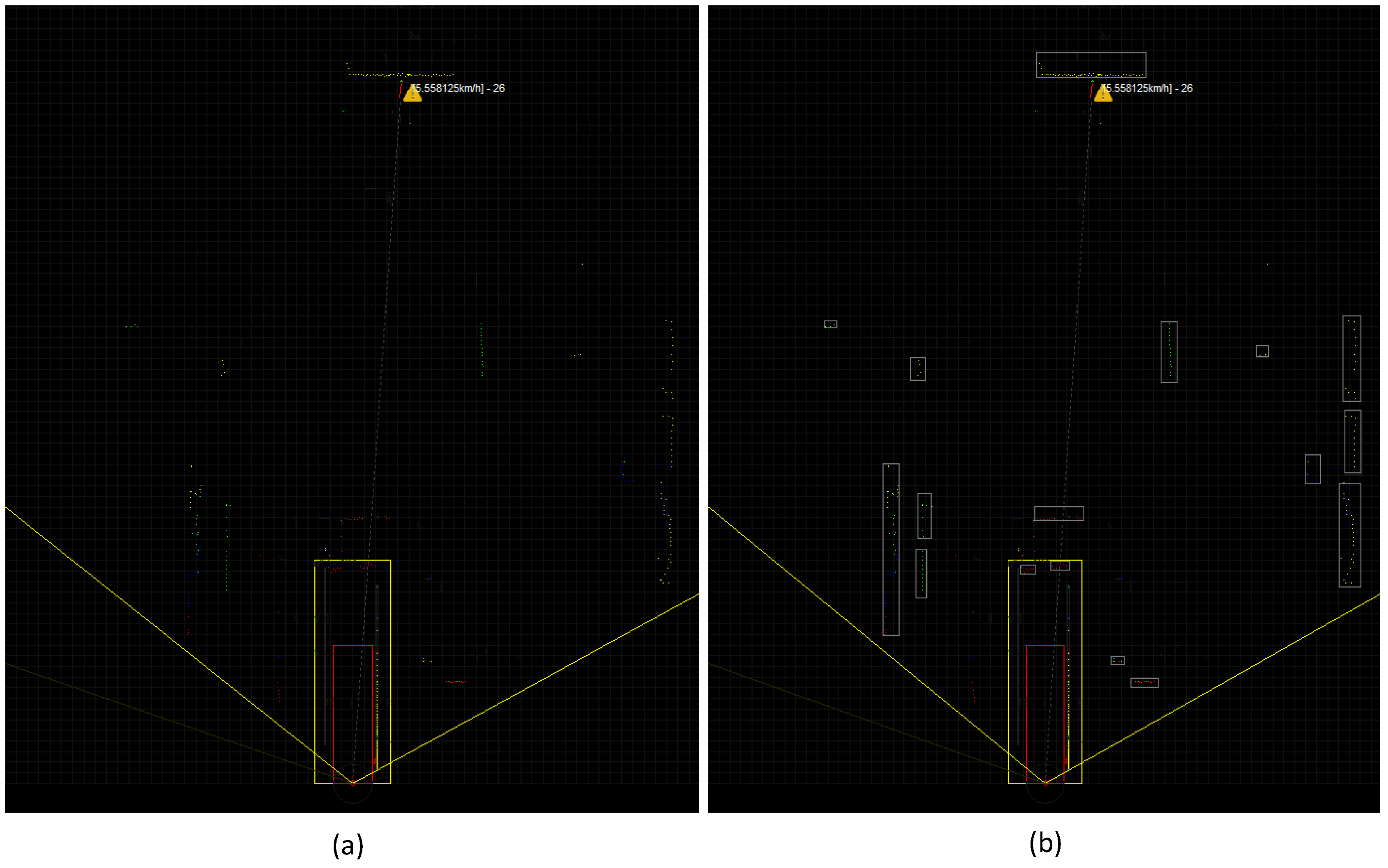
Before and after segmentation process outputs can be seen
Figure 4.
3.2. Object Classification
After having identified which points belong to the same obstacle, object classification is performed to distinguish typical road objects like cars, trucks, bicycles and pedestrians. Normally, it is expected to have dependable object classification in every scan of laser scanners, but this does not happen because of laser scanner sensor characteristics. The shape of the same object can alternate depending upon its position. One way to overcome this problem is to take into consideration as many features as possible from previous object detections, especially dynamics and dimensions.
It is not possible to achieve a highly confident classification in the first scan of an object when it first appears. In this study, the Majority Voting Scheme (MVS) classification method is used. MVS method is based on a voting scheme considering every hypothesis over time, until reaching a high classification confidence [
43]. In this method, classification is improved over time. Therefore, a better classification can be obtained after several frames.
Each feature that characterizes the object represents a voter actor, where the weight of the vote depends on the influence of the related feature to characterize the object and on the value n of that feature, given by
Figure 5 and Expression (7).
The confidence level is reached with the addition of the votes of all the actors (7). When some of the hypotheses achieve an acceptable value, it is assumed that the object is classified as belonging to the type of that hypothesis.
MVS does not have a self-consistent mathematical framework in order to support its stability and consistency. Nevertheless, the results, which can be seen [
41], show its feasibility.
3.3. Kalman Filter Tracking
Object tracking is a very important phase for CAS. There are many object tracking methods in literature [
4,
18]. One of the most common method is Kalman Filter tracking [
6,
7,
41]. Kalman Filter provides a recursive solution to the optimal filtering problem and it can be applied to stationary as well as nonstationary environments.
In this study, the position of detected segments is tracked over time using the Kalman Filter. The tracking algorithm estimates the position and velocities of objects from current observation and state predicted.
Kalman Filter consists of two main stages. In the first stage, the state of the process is predicted. In the second stage, predictions are corrected or updated by using measurements. Prediction and update equations of discrete-time Kalman Filter are as below:
1. Predict: For each time step t, the predicted state at this time step
is given by;
where x and y represent the coordinates of the object and V
x and V
y represent the objects velocity. To use Kalman Filter, the objects are considered moving at constant velocity and constant acceleration.
The transition matrix F is:
Converting u
t into state space matrix B is:
For concluding Kalman Filter prediction,
error covariance matrix forward one-time step:
where P is the matrix representing error covariance in the state prediction and
is the process noise covariance.
2. Update: After predicting the state
, the Kalman Filter computes Kalman Gain to correct the state estimate
Kalman Gain is calculated as below:
where R is measurement noise covariance.
After predicting the state
and its error covariance at time
t using the time update steps, the Kalman Filter can update the state estimate using Kalman Gain and measurements that are derived from the laser scanner:
where y is the measurement derived from the laser scanner. It contains two dimensions (x and y coordinates) and it has the form for all of the different tracking algorithms for n tracking algorithm as below:
As a result, the H matrix (observation matrix), which is the matrix of converting state space into measurement space, has the form;
Finally, Kalman Filter updates error covariance
into
:
Although Kalman Filter is a powerful tool for tracking, there is a difficulty in combining arbitrary tracking algorithms, as measurements come from computing the Kalman Gain. Normally, the measurement noise covariance matrix, R is difficult to determine, but thanks to laser scanners’ highly accurate measurement, a small noise covariance is sufficient for position measurement.
3.4. Risk Assessment System
After obtaining the location of moving or static objects as results of object recognition and tracking module, risk assessment module estimates the time-to-collision for each object. In this estimation, the velocity of each object is considered to be constant and the shortest distance of the closest point of the object to the test vehicle is detected by laser scanning sensor. Thus, time-to-collision and predicted collision place are estimated by using the knowledge of relative velocities and the shortest distance. However, since objects can change their motion, these estimations cannot be exact and the distribution of likely future states of the objects must be taken into consideration. Since pedestrians, unlike vehicles, are capable of making quick maneuvers, risk assessment module has extra time tolerance after the acoustic warning for pedestrians when compared to the vehicles.
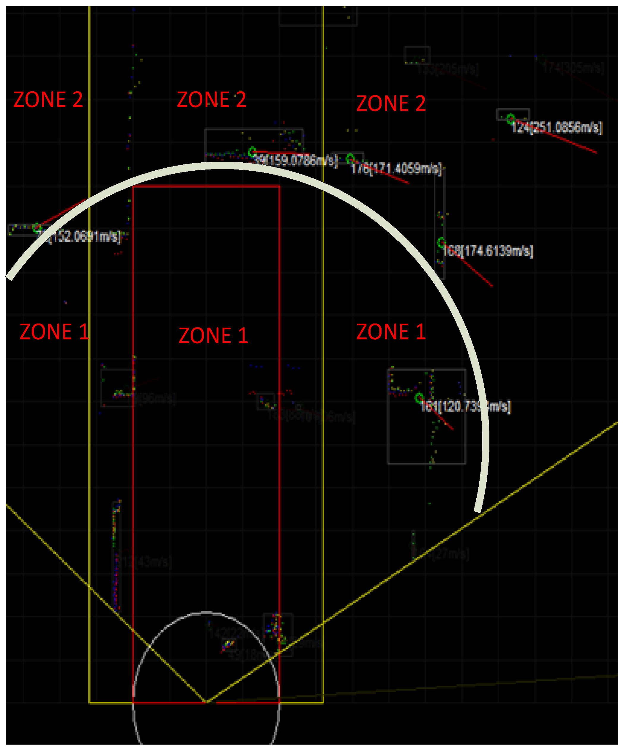
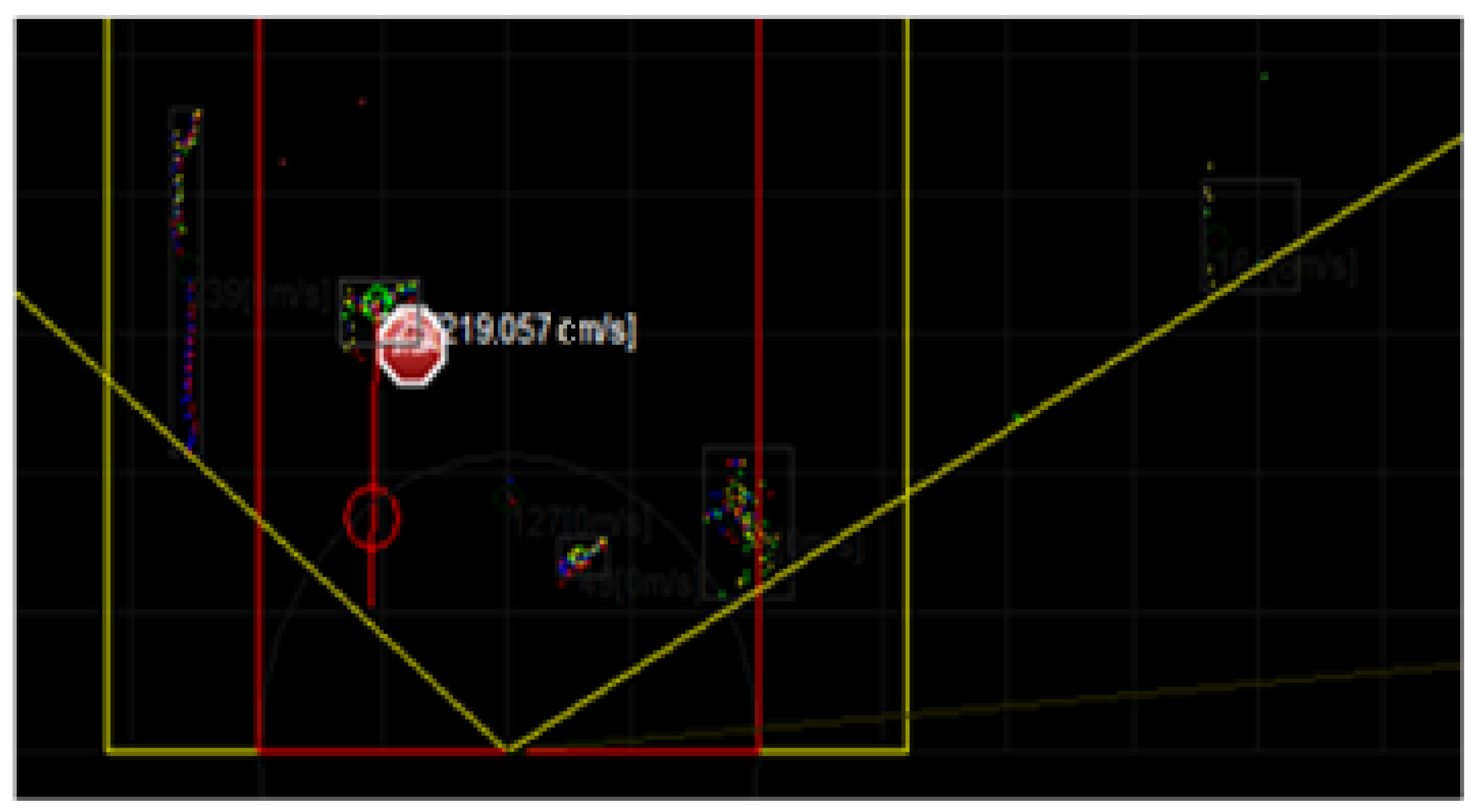
In this study, the screen display obtained from the laser scanner is divided into two zones when considering the tram’s maximum velocity, dimensions, and route. The laser scanner scans the area with an angle of 110°. As seen in
Figure 6, Zone 1 is the “Danger Zone”, whereas Zone 2 is the “Safe Zone”. Collision probability depends on not only the zone but also the type and velocity of the object. Three different collision scenarios are evaluated in the designed system. These scenarios are as follows:
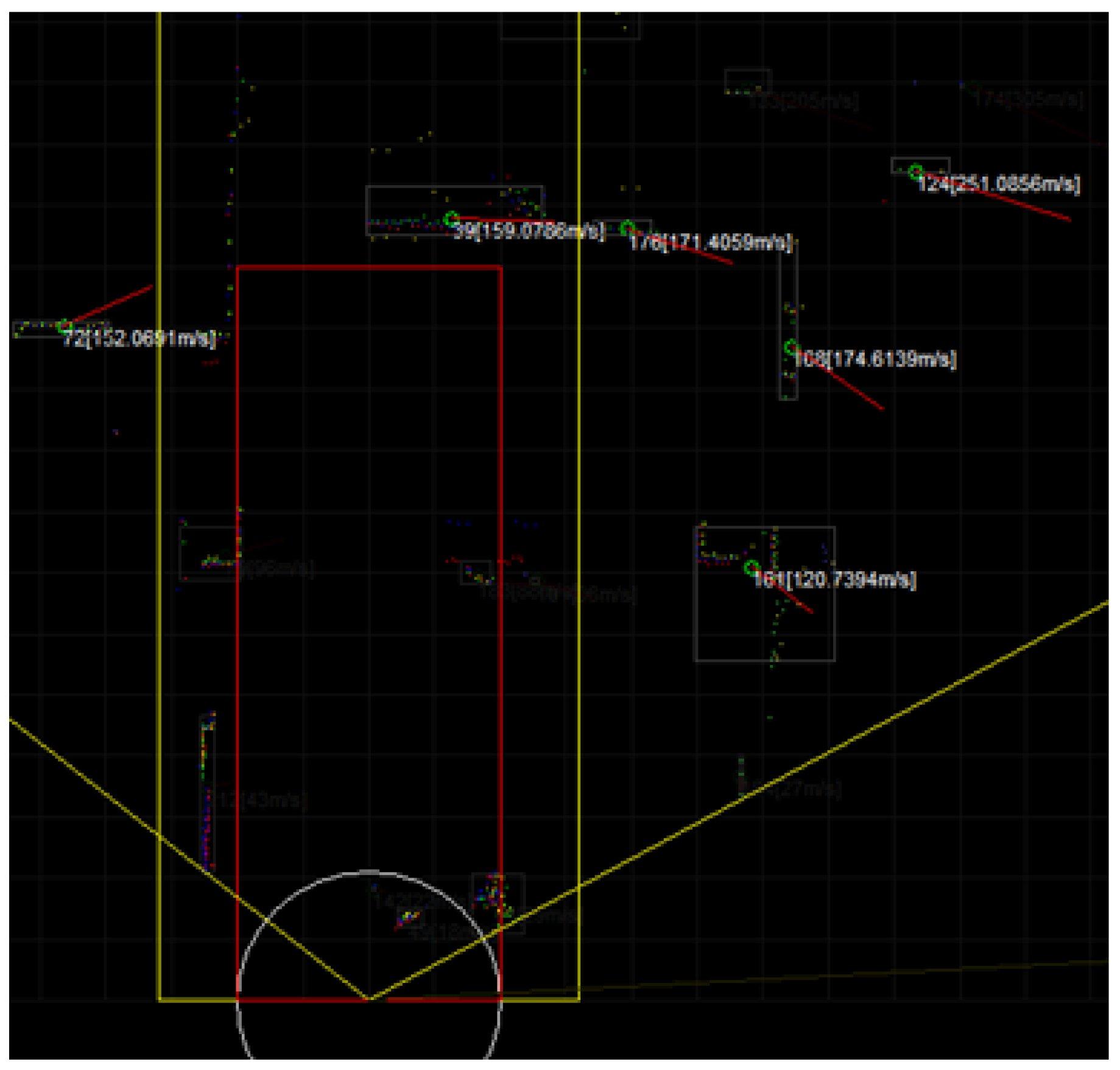
1. No Collision Probability:
The scenario in which there is no probability of a collision when considering the heading, velocity, position, and distance of the objects that are detected on the tram line or in the vicinity of the line. In this case, shown in
Figure 7, there is no need for warning signals or brake actuation.
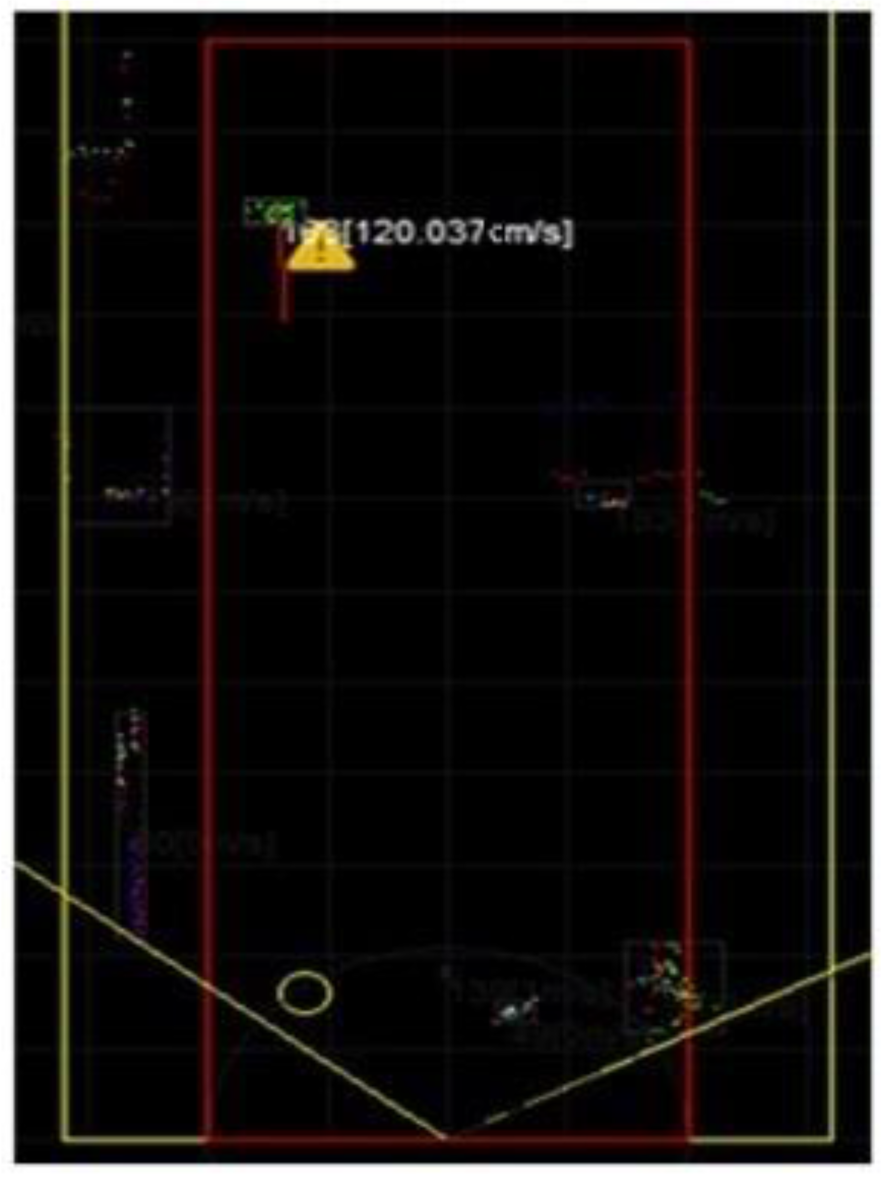
2. Collision Probability:
This scenario is divided into two cases. In the first case, the detected object is in the Safe Zone but getting closer to the Danger Zone depending on its velocity and heading. In the second case, although the object is in the Danger Zone, it is moving in the same direction as the tram and slower than the tram. In this case, an exclamation mark appears on the screen and an alarm signal is played (
Figure 8).
3. Collision Highly Probable:
The scenario in which the probability of collision is very high considering the position, velocity, heading, and distance of the detected object. In this case, a stop sign appears on the screen, an alarm signal plays and automatic brakes are activated if the tram driver does not respond in two seconds (
Figure 9).
4. Field Tests
Field tests were implemented at the facilities of Durmazlar Machine Inc. in the city of Bursa, Turkey.
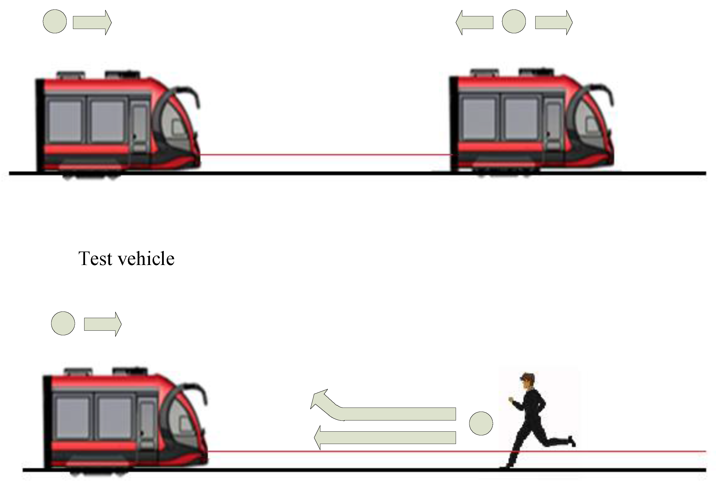
When the dynamics of objects are taken into account, there are two different types of objects that can be encountered in a traffic scene: pedestrian and vehicle. These tests are carried out with two different objects with various configurations, as seen in
Figure 10. The first case is a LRV on the same line, the second one is a pedestrian on the route of the vehicle and the third one is multiple pedestrians and another LRV. All of the tests are implemented while the test vehicle is at the velocity of 20 km/h.
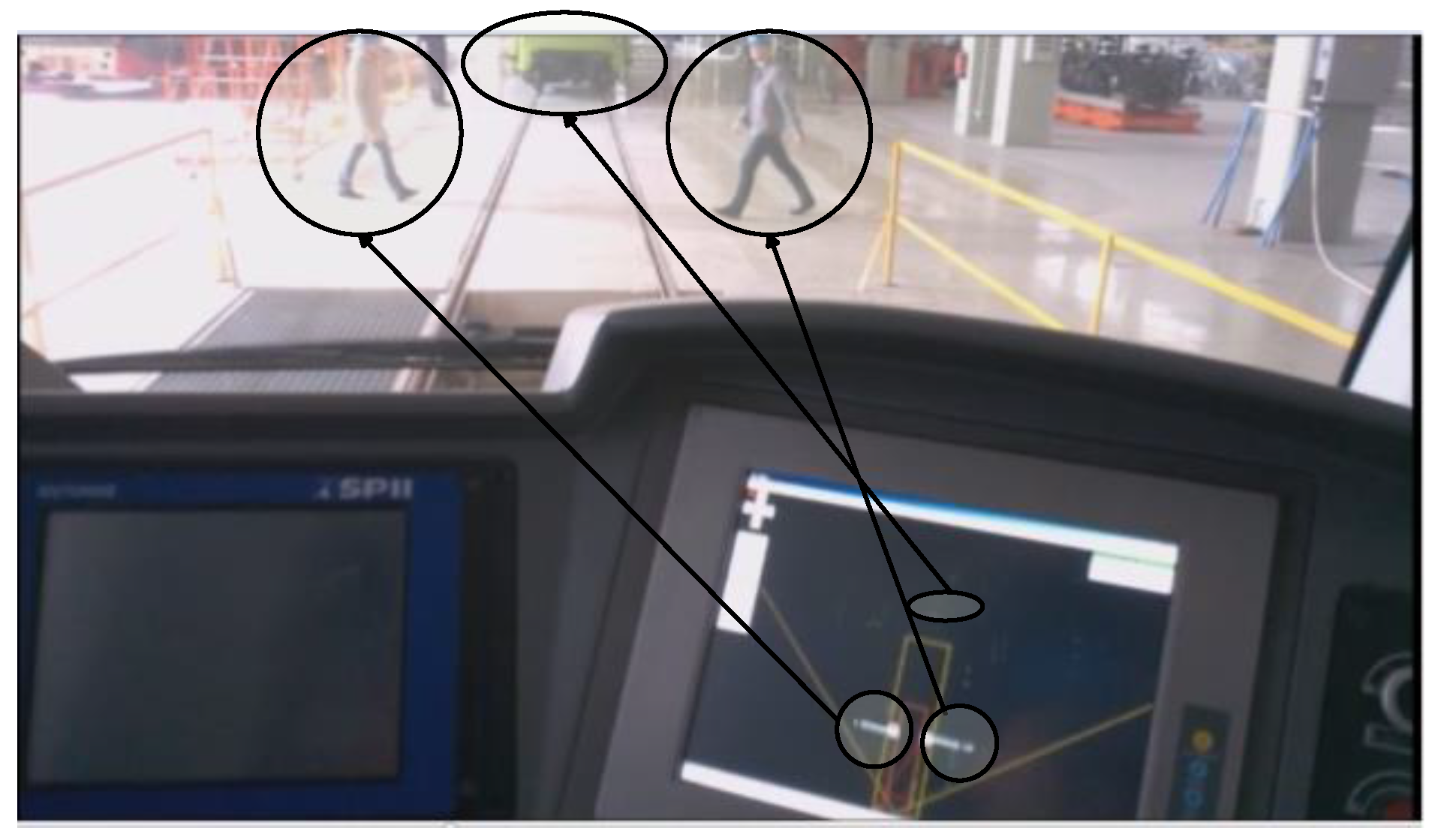
Some specific test scenarios were staged such as running pedestrian towards to test vehicle and dangerously crossing pedestrians. All of the test scenarios can be seen
Table 1.
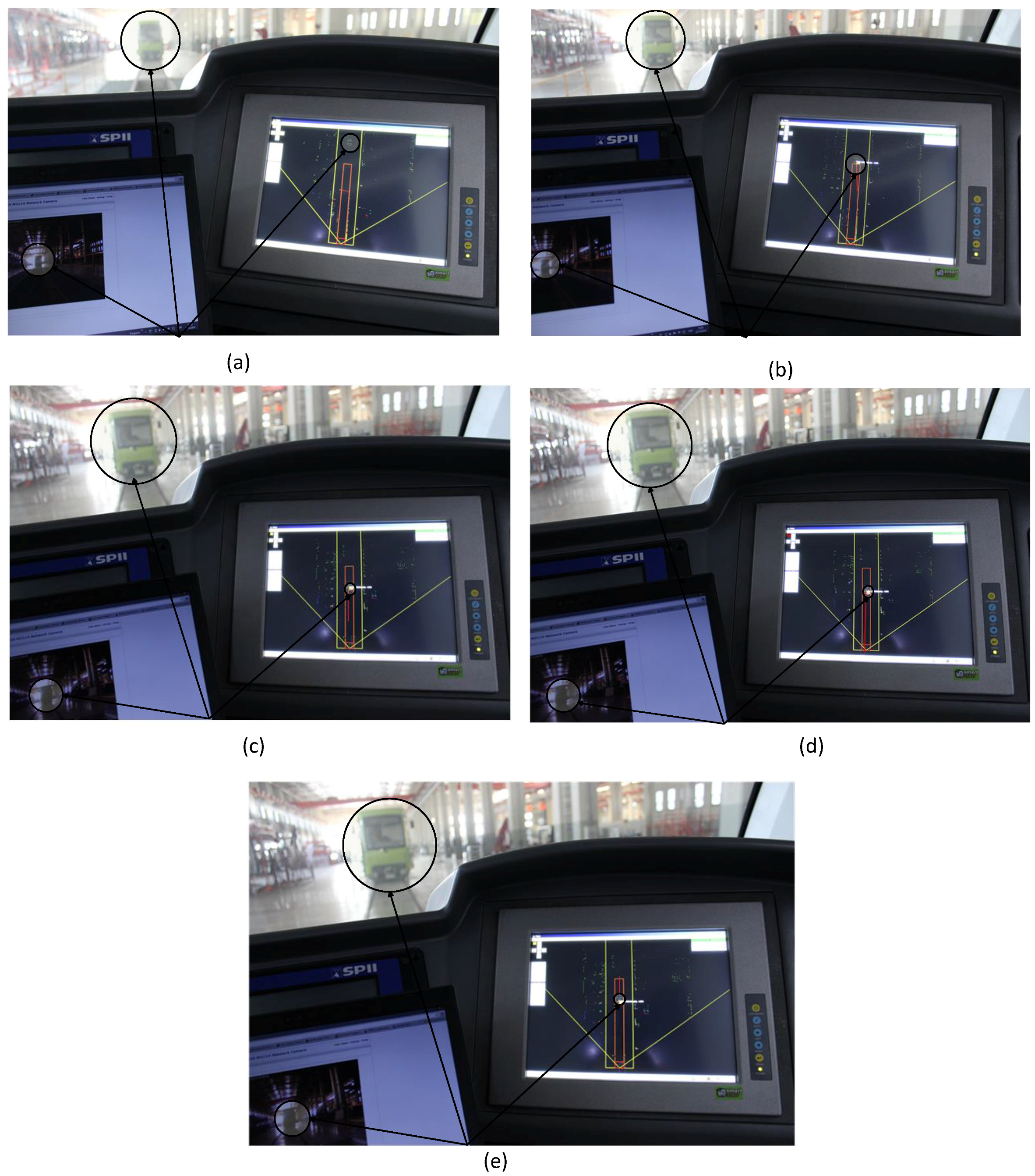
In the first scenario, while the test vehicle is moving with a velocity of 20 km/h, there is another static LRV on the same line (
Figure 11a). In terms of its position, the static vehicle is not in the danger zone and because it is not moving, it does not pose any danger to the test vehicle. On the other hand, since the test vehicle is moving with a velocity of 20 km/h, visual signals will appear as static LRV enters the danger zone. The second scenario that can be seen in
Figure 11b is another LRV on the same line is approaching the test vehicle with a velocity of 10 km/h. At the same time, the test vehicle is proceeding with a velocity of 20 km/h. The approaching LRV enters the danger zone and its heading is towards the test vehicle. For the moment, there is no absolute probability of collision. So, only a visual signal appears on the screen for the tram driver. At this point, there is no need for an acoustic warning or brakes to activate. The third scenario is the next step of the scenario, and it can be seen in
Figure 11c. The LRV approaching the test vehicle with a velocity of 10 km/h is very close to the test vehicle. At the moment, it is not yet possible for a collision to occur in two seconds, but it can happen after this two-second time period. At this point, there is no need for automatic brakes. In the next scenario, another LRV approaching the test vehicle with a velocity of 20 km/h enters the danger zone (
Figure 11d). There is a possibility of collision in two seconds because of its position, velocity, and heading. A visual signal appears on the screen and an acoustic warning is activated. Automatic brakes activate at this point because the tram driver does not step on the brakes and the probability of collision is very high. In
Figure 11e, the scenario shows an incident that can frequently occur in routine travels of the tram. There is an LRV with the same heading and velocity of the test vehicle. Although the other LRV is in the danger zone, its velocity and its heading are the same as the test vehicle. In such a situation, a visual signal appears on the screen to warn the tram driver, but there is no probability of a collision in a short period of time. Thus, the acoustic warning and automatic brakes are not activated.
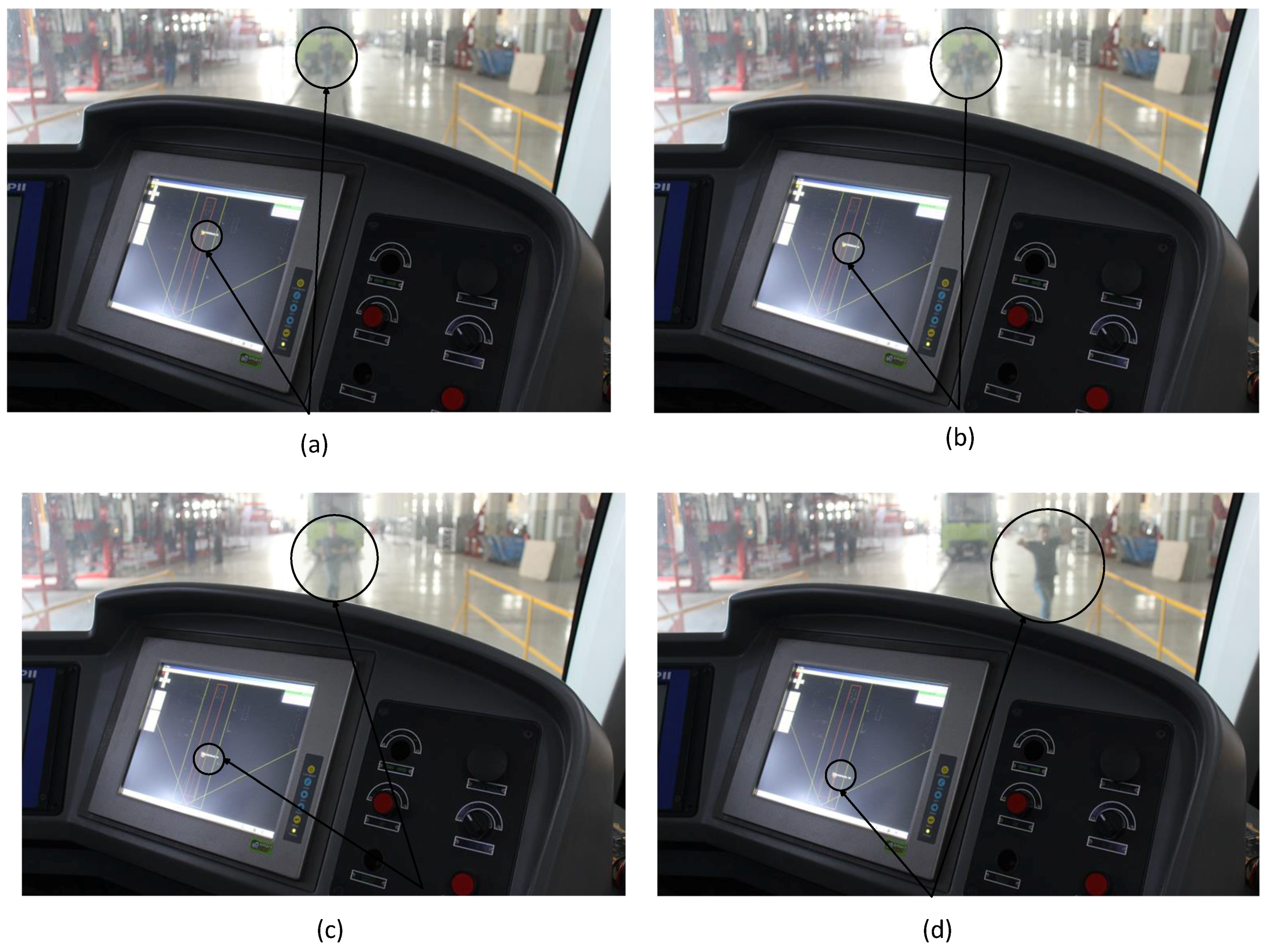
In the
Figure 12a scenario, a pedestrian is running with a velocity of 5 km/h towards the test vehicle. The pedestrian is in the danger zone, but the probability of collision is not very high. A visual signal appears on the screen for the tram driver, but the acoustic warning is not activated. The next scenario that can be seen
Figure 12b, a pedestrian is running with a velocity of 11 km/h towards the test vehicle and it is closer to the vehicle; the automatic brakes are not activated. A visual signal for the tram driver and an acoustic warning for the pedestrian are activated. At this point, it is not necessary for automatic brakes to activate. The pedestrian in the
Figure 12c scenario is running towards the test vehicle with a velocity of 14 km/h. Although the acoustic warning was activated the heading of the pedestrian is not changed and is still towards the test vehicle. Taking into account the velocity and heading of the pedestrian, a collision is highly possible in a two-second time period. So, the automatic brakes are activated. In the
Figure 12d scenario, the pedestrian running with a velocity of 13 km/h is in the danger zone, and a collision is highly probable. Although the pedestrian has changed his heading, there still exists a probability of a collision when the dimensions of the tram are taken into account. Because of this, the automatic brakes are activated.
There are two pedestrians crossing the tram line and a static LRV in the scenario that can be seen in
Figure 13. In terms of its position, the static LRV does not pose a danger to test vehicle. Pedestrians are in danger zone, but probability of collision is not very high. A visual signal and an acoustic signal are activated.
In the first five test scenarios (
Figure 11) and 7th, 8th, and 9th scenarios (
Figure 11b–d) object detection and classification results were good and CAS worked well. In the sixth test scenario (
Figure 11a), a pedestrian was detected by algorithm but was misclassified. Because, the pedestrian suddenly started to move and he kept moving slowly. Since the classification algorithm is closely related to the time, object is detected after a few second delay as a pedestrian. In scenario 10, system first classified pedestrians and static LRV. When two pedestrian got closer to each other, the classification algorithm could not distinguish two pedestrians. Despite the misdetection of the two situations, the CAS issued the appropriate alarm because pedestrian was detected as an object.
5. Conclusions and Future Work
This study presents a CAS algorithm for LRV to avoid the collision by using only a multilayer laser-scanning sensor mounted on a test vehicle called “Silkworm”. The proposed system has three modules. The first one is a sensor module that is based on a state-of-the-art laser scanning technology. The second module, called “recognition and tracking module” has three submodules to identify and track the obstacles in the scanned area. After identifying and tracking the obstacles, the third module calculates the collision probability. The whole system was applied to the Silkworm, which was manufactured by Durmazlar Machine Inc., Bursa, Turkey. Initial tests have been carried out at the Durmazlar Machine Inc. test facility. In normal traffic conditions, the objects that the system will encounter mostly would be pedestrians and other vehicles, so the test objects were restricted to pedestrians and other LRVs. Three primary test scenarios have been implemented. The first case is a LRV on the same line, the second one is a pedestrian on the route of the test vehicle, and the last one consists of both a LRV and multiple pedestrians on the route of the test vehicle.
It has been observed that designed recognition and tracking module is robust against rapidly moving and quick maneuvering objects and is able to follow a pedestrian running at over 6 m/s. The collision avoidance rate of the system is high due to its three phase warning system: visual warning for tram driver, acoustic warning for pedestrians, and finally automatic braking. Throughout the ten scenarios tested (
Table 1), the laser scanning sensor has successfully detected all of the objects. The classification algorithm failed in two situations.
The pedestrian suddenly starts to move and keeps moving slowly (
Table 1 Scenario 6)
Two pedestrians get close to each other (
Table 1 Scenario 10)
The qualification processes have not yet been completed, driving tests in the city have not begun. Therefore, the designed system could not be tested in various weather conditions with various scenarios. Therefore, our future work will consist of implementing adverse weather conditions and varying scenarios during the qualification phase. Furthermore, to improve the efficiency of detection and classification algorithms, the next research step will include developing a new method of laser/camera fusion or laser/radar fusion. On the other hand, the system that uses only a laser scanning sensor was used for the first time in real-time tests for trams.
CAS that warn of collision and automatically brake in an emergency are increasingly spreading in rail transportation systems and they provide the basis for automated trams. All kinds of vehicles are expected to be smarter in the near future, so it is the first step for unmanned railway vehicles.
