Article

Printability Study of Bioprinted Tubular Structures Using Liquid Hydrogel Precursors in a Support Bath

Department of Mechanical Engineering, Stevens Institute of Technology, Hoboken, NJ 07030, USA
*
Author to whom correspondence should be addressed.
Appl. Sci. 2018, 8(3), 403; https://doi.org/10.3390/app8030403
Submission received: 31 January 2018 / Revised: 28 February 2018 / Accepted: 6 March 2018 / Published: 9 March 2018
(This article belongs to the Special Issue Biofabrication: From Additive Bio-Manufacturing to Bioprinting)

Abstract

:

Featured Application

Bioprinting of complex cell-laden tissue constructs that mimic the human vascular tissue structure.

Abstract

Microextrusion-based bioprinting within a support bath material is an emerging additive manufacturing paradigm for complex three-dimensional (3D) tissue construct fabrication. Although a support bath medium enables arbitrary in-process geometries to be printed, a significant challenge lies in preserving the shape fidelity upon the extraction of the support bath material. Based on the bioprinting in a support bath paradigm, this paper advances quantitative analyses to systematically determine the printability of cell-laden liquid hydrogel precursors towards filament-based tissue constructs. First, a yield stress nanoclay material is judiciously selected as the support bath medium owing to its insensitivity to temperature and ionic variations that are considered in the context of the current gelatin-alginate bio-ink material formulation. Furthermore, phenomenological observations for the rheology-mediated print outcomes enable the compositions for the bio-ink material (10% gelatin, 3% alginate), in tandem with the support bath medium (4% nanoclay, 0.5% CaCl2), to be identified. To systematically evaluate the performance outcomes for bioprinting within a support bath, this paper advances an experimental parametric study to optimize the 3D structural shape fidelity by varying parameters such as the layer height, extrusion flowrate, printing temperature, and printhead speed, towards fabricating complex 3D structures with the stabilization of the desired shape outcome. Specifically, it is found that the layer height and printhead speed are determinant parameters for the extent of successive layer fusion. Moreover, maintenance of an optimal bath temperature is identified as a key parameter for establishing the printability for the hydrogel bio-ink. Studying this effect is enabled by the custom design of a PID temperature control system with integration with the bioprinter for real-time precision control of the support bath temperature. In order to qualify the printed construct, a surface irregularity metric, defined as the average height difference between consecutive local maximum and minimum points of the binary image contour for the printed structure, is advanced to evaluate the quality of the printed constructs. Complex one-to-four bifurcating tubular structure prints demonstrate the applicability of the optimized bioprinting parameter space to create exemplar 3D human vessel-like structures. Finally, a cell viability assay and perfusion test for a printed cell-laden tubular element demonstrates high cell survival rates and leakage-free flow, respectively.

1. Introduction

Three dimensional (3D) printing enables fabrication of complex structures [1,2,3]. Among the established 3D printing techniques, material extrusion is a prevailing technique due to facile process implementation under relatively moderate ambient conditions and a diverse material palette [4]. As a result of these materials processing characteristics, microextrusion-based bioprinting (micro-EBB) of cell-laden biopolymer materials has been advanced to fabricate analog tissue constructs towards targeted cell-based models and therapeutic applications [5,6,7,8,9]. The micro-EBB materials fabrication process extrudes suspensions of live cells within hydrogels, enabling tissue scale constructs with high flexural and mechanical strength and cell proliferation rates [10]. The operating principle behind the micro-EBB techniques is one that combines a fluid-dispensing system with an automated robotic system for precision printing. During printing, computer-controlled deposition of cells within continuous filament structures results in rapid fabrication of the desired 3D customized structures with adequate mechanical stiffness [11,12,13]. Various bioprinting process innovation strategies have recently been developed, including single axis printing and co-axial printing. Moreover, beyond the traditional implementation of bioprinting in an air medium, emerging techniques have implemented printing in a liquid bath or hydrogel support bath medium. Among the various bioprinting techniques, extrusion within a support bath medium is a burgeoning technique that enables complex 3D structured materials processing of low viscosity liquid hydrogel precursors [14,15,16,17]. By depositing structural filaments within a support bath, the limitations of conventional printing in air processing configurations can be mitigated, including clogging [18,19], gravity-induced structural collapse with weak interfacial strength [20], and the absence of a support structure [21,22]. Specifically, bioprinting within a support bath enables low viscosity materials processing to minimize the extent of the material occlusion of the extruding nozzle. Also, the layer-to-layer interfacial strength can be maintained due to the characteristically low surface tension of the bio-ink within a liquid medium [15]. Also, the bath material serves as a provisional frame for the in-process support of the printed bio-ink towards an integrated 3D structure with high shape fidelity upon post-process material gelation.
To better understand bioprinting performance outcomes within a support bath material, the key consideration is how to confer and maintain the complex structural properties, including construct shape fidelity and mechanical stiffness, in the context of low viscosity prints. Related work includes studies in which the printability of gelatin-alginate hydrogel blends within a yield stress bath has been demonstrated to yield complex 3D structures [10]. Moreover, print feasibility studies with various materials, including PDMS and agarose hydrogels, have been reported for hydrophilic support baths such as Carbopol gel and perfluorotributylamine [17,23]. Supermolecular hydrogels have also been printed in self-healing hydrogels to achieve fine, multi-material structures [24]. Developing a support bath material is critical for the printing of liquid hydrogel precursors. Currently, gelatin microparticles, Carbopol microgels, nanoclay, and pluronic F127 represent some of the most promising candidate support bath materials. Gelatin is a thermosensitive material that can serve as a support bath in gel form at a relatively low working temperature (<25 °C), which can be removed by increasing the temperature. In this paper, gelatin is selected as a component of the bio-ink, thereby limiting the use of gelatin as the prescribed support bath material. The ion-sensitive Carbopol can be used to print hydrogels without an ionic cross-linking post-processing step. It is reported that the printed outcome exhibits poor surface quality when using Carbopol as a support bath [15]. The pluronic F127 is stable at a temperature range of 25 °C–40 °C, which is typically used as mold and sacrificial material for bioprinting [5,25]. Pluronic F127 has poor mechanical strength and tends to dissolve in aqueous environments, which may affect printed structure shape properties while using liquid hydrogel precursors [26]. The nanoclay is selected here as the support structure due to its superior properties such as the ionic insensitivity, thermal stability, and unltraviolet transparency. As a yield stress bath material, the nanoclay formulation begins in the gel state before processing. When the bioprinting nozzle translates in the nanoclay support bath, nanosilicates around the nozzle experience shear stress higher than the yield stress of the nanoclay, causing a material phase transition from the gel to sol state. After the nozzle travels away, the region rapidly recovers to its native gel state when the shear stress falls below the yield stress.
Although bioprinting within a support bath has been widely investigated by using a different fluid-dispensing system and hydrogel materials with different rheological properties, there are fundamental questions about how the relationships can be mapped between the printing process parameters and the printing performance outcomes. To systematically evaluate the related outcomes for bioprinting within a support bath, this paper advances an experimental parametric study to optimize the 3D structural shape fidelity by tuning the process parameters including the layer height, extrusion flowrate, printing temperature, and print head speed. The Table 1 lists the key parameters and their values that will be investigated in this study.
The tubular structure, which is widely studied as a mimic of human vessel tissue, is selected as an example to be investigated [13,23]. Next, optimal printing conditions are then explored to achieve 3D tissue constructs with a smooth surface, shape integrity, and adequate stiffness. Based on the experimentally optimized printing condition, this paper aims to provide needed insight into how cell-laden hydrogel materials can be systematically processed under the emerging bioprinting support bath paradigm to produce tissue constructs with precise control of structural properties.

2. Materials and Methods

2.1. Cell Culture and Viability Assay

Normal human dermal fibroblast (NHDF) cells are cultured in Dulbecco’s modified Eagle’s medium (DMEM) with 15% fetal bovine serum (FBS), 1% penicillin-streptomycin (P/S) solution. The NHDFs are cultured in an incubator at 37°C and with 5% CO2. The growth medium is changed every 2 days. Dissociation of NHDFs with 0.25% trypsin is applied at approximately 90% confluence to passage the cells. Each live cell suspension is fluorescently stained with Calcein-AM (2 μmol/L, Enzo), centrifuged, re-suspended in the liquid hydrogel precursor, and visualized post-print with a wide-field fluorescent microscope.

2.2. Material Preparation

2.2.1. Alginate-Gelatin Blend Preparation

Gelatin powder (type A, 300 bloom, with average molecular weight of 100,000, Sigma-Aldrich, St. Louis, MO, USA), and sodium alginate powder ((C6H7NaO6)n, with molecular weight of 216.121 g/mol, (Sigma-Aldrich, St. Louis, MO, USA) are dissolved in 1 × Dulbecco’s phosphate-buffered saline (DPBS, without calcium and magnesium) at 95 °C to make gelatin-alginate solution with various concentrations. A warm gelatin-alginate solution is sterile-filtered with 0.45 μm and 0.20 μm filters and then stored at 4 °C for future use. A calcium chloride (CaCl2) stock solution is prepared by dissolving CaCl2 in DI water at a concentration of 2% w/v. A sodium chloride (NaCl) stock solution is prepared by dissolving NaCl in DI water at a concentration of 0.9% w/v.

2.2.2. Nanoclay Support Bath Preparation

The Laponite nanoclay (Na0.7Si8Mg5.5Li0.3O20(OH)4) is in the form of disk shaped particles with thickness 1 nm and diameter 25 nm. Laponite EP nanoclay (BYK Additives Inc., Gonzales, TX, USA) is used as a yield stress bath to support hydrogel printing. Laponite EP nanoclay powder is dispersed in DI water under vigorous stirring for 24 h to ensure uniform dissolution. A range of nanoclay concentrations has been tested. The 4% nanoclay with 0.5% CaCl2 is finalized as the optimal for both rheological properties (moderate viscosity). The lower concentration of nanoclay fails to support the printing of complex structures, causing material discontinuities during printing. The higher concentration of nanoclay is more viscous, exerting more pressure on the printed cell-laden filament within the bath during printing. A 4% nanoclay formulation is prepared to investigate the effects of the support bath properties on the filament formation. To improve the hydrogel cross-linking properties of the 3D structure, the 4% nanoclay with 0.5% CaCl2 is prepared as the optimal bath concentration for printing.

2.3. Bio-Ink Formulation

The initial cell-free bio-ink is constituted at 20% w/v gelatin and 6% w/v alginate. When bubbles are observed upon loading into a syringe material reservoir, the syringe is placed at an ambient temperature of 37 °C to accelerate bubble removal. The bio-ink formulation is prepared by mixing gelatin-alginate hydrogels and the NHDF cells. The bio-ink consisting of alginate, gelatin, and cells is prepared and processed for the final fabricated 3D bifurcation structure. As an example, 3% w/v alginate, 10% w/v gelatin with a prescribed bio-ink cell density is prepared by first collecting the NHDFs by centrifugation at 1000 rpm for 5 min. The NHDF cells are dispersed into a 0.5 mL solution of DPBS by gently pipetting the cell pellet so as to avoid bubble formation that may confound the cell density measurements. The mixed solution of 0.5 mL 6% w/v alginate and 20% w/v gelatin at 37 °C is then added to the cell suspension to yield a final bio-ink formulation with 3% w/v alginate and 10% w/v gelatin with 2 × 10⁶ cells/mL. For complete mixing, the bio-ink is maintained at 37 °C and transferred to 4 °C for 5 min to induce rapid gelation with minimal time-dependent cell settling. Prior to printing, the bio-ink is warmed at a prescribed processing temperature for 10 mins.

2.4. 3D Bioprinter System Configuration

All cell-laden constructs are created by implementing an in-house 3D bioprinter based on a customized 3-axis CNC machine mounted with an independently addressable printing head. The toolpath is designed and transformed into G-code using Matlab (MathWorks, Inc., Natick, MA, USA), and then imported to the stand-alone open source software grblController to control the three-axis translational platform. A temperature-controlled heating pad (New Era Pump Systems, Inc., Wantagh, NY, USA) is wrapped around the bio-ink syringe to maintain the bio-ink material at 37 °C. The bio-ink material formulation (both cell-laden experimental and cell-free control groups) is loaded into a 3ml syringe-based material reservoir equipped with a 22 gauge nozzle (EFD, Inc., Madison Heights, MI, USA). A bio-ink deposition flowrate of 1–10 mL/h is controlled by modulating the motor rotation speed.

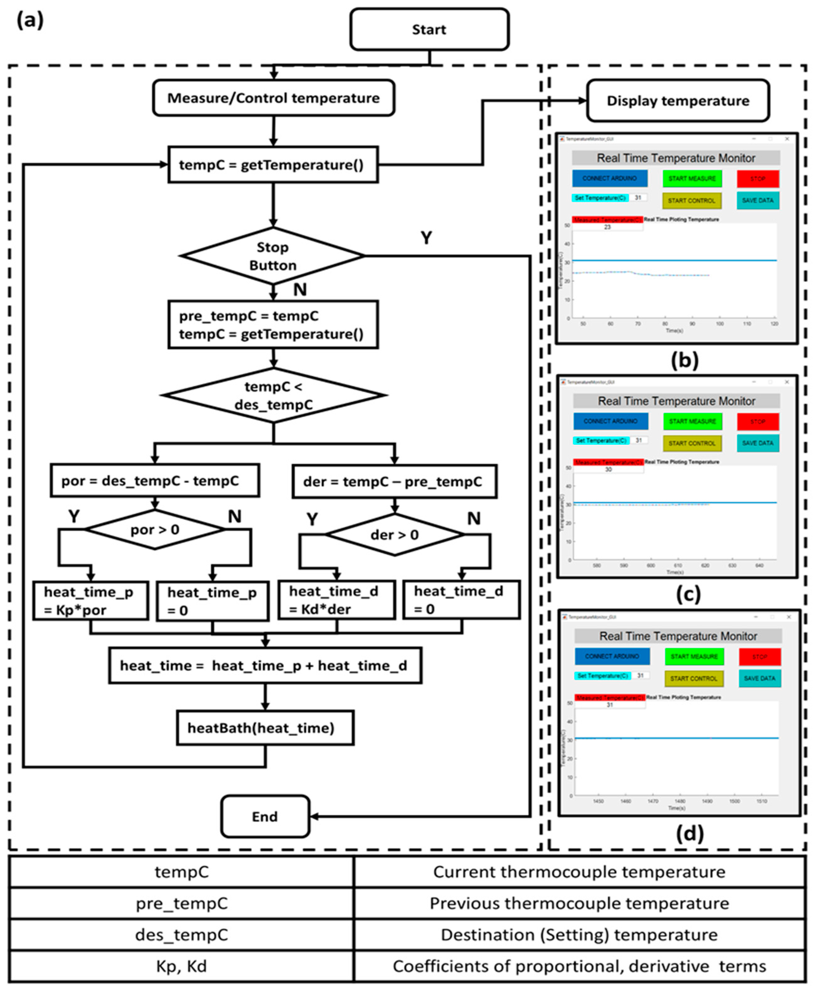
2.5. Temperature Control System for Support Bath

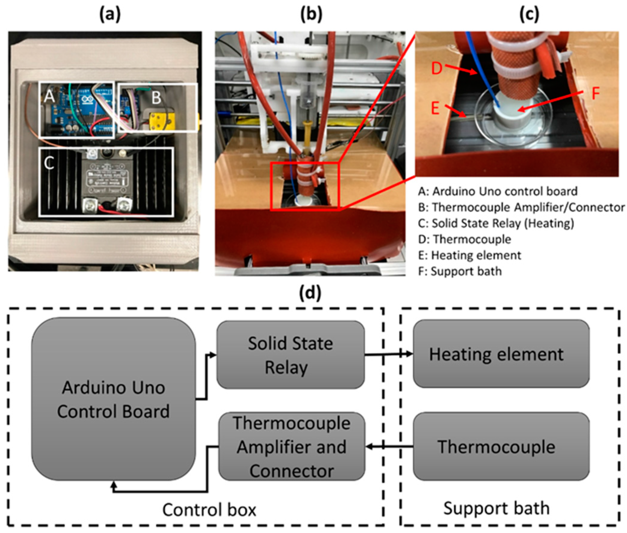
The support bath temperature is controlled by a customized temperature control system. The control system contains an Arduino Uno board, a solid state relay, a heating unit, a thermocouple amplifier (MAX31855), and a thermocouple. The system configuration is shown in Figure 1. The control box is connected to a host computer. A software “Real Time Temperature Monitor” with GUI is programmed in Matlab to communicate with the Arduino board. The software functions to measure the current temperature, and control the object temperature by using a proportional-integral-derivative (PID) controller. The control algorithm details are shown in Figure 2. The support bath is pre-heated to the desired temperature to save the temperature control time. The printing platform is surrounded by a latex sheet to mitigate heat losses. 
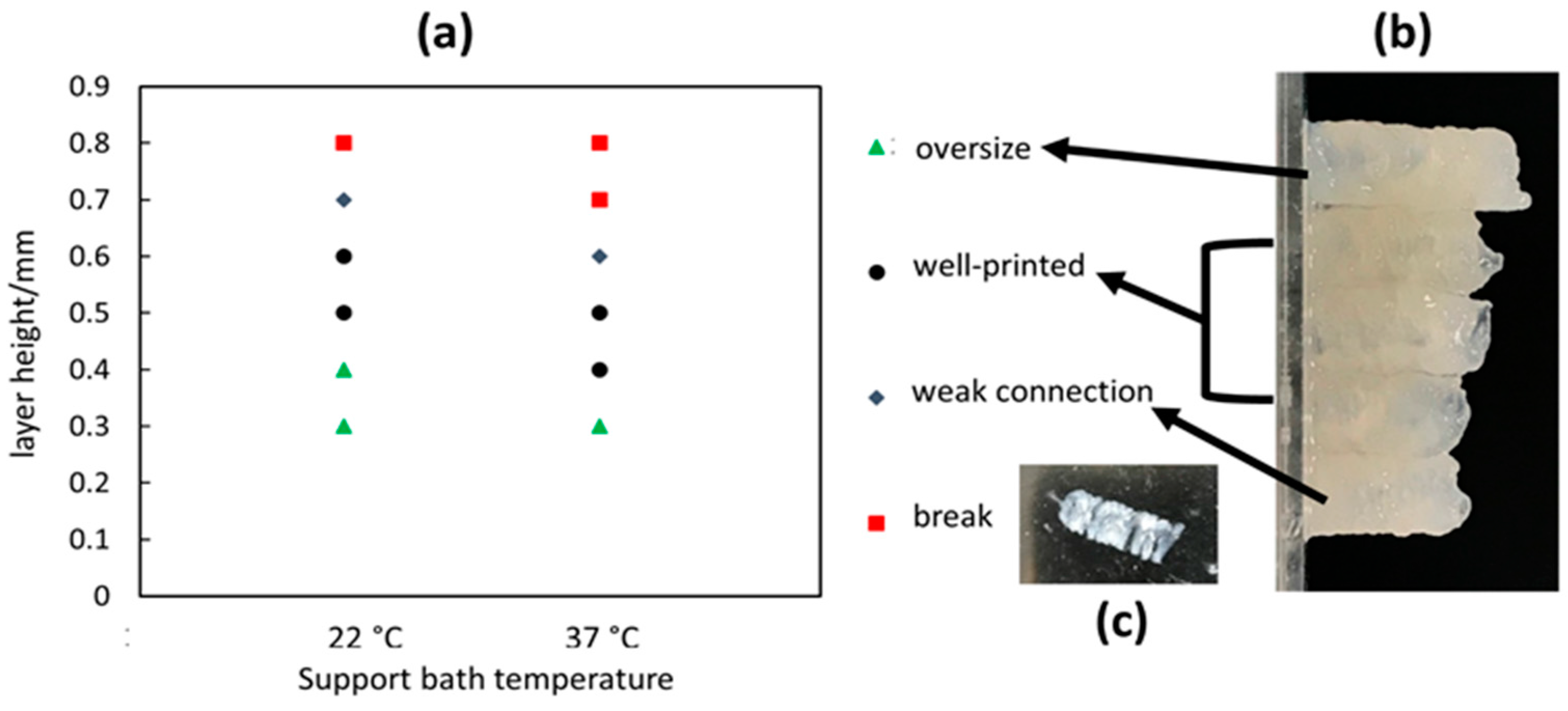
Figure 2b–d shows the temperature control procedure. The set temperature is 31 °C, and the bath temperature is gradually increased and stabilized at 31 °C within 10 min. The customized temperature control system aims to maintain the support bath conditions. This is of particular importance when ambient temperatures fall below 22 °C, resulting in fast gelation of the gelatin material with accompanying nozzle occlusion.

2.6. Post-Processing of Printed Constructs

After printing, the constructs are first immersed in a 0.9% NaCl2 to rinse the support bath, followed by the addition of 2% CaCl2 solution to physically cross-link the sodium alginate material for 10 mins. Any residual nanoclay support bath material is removed by gently pipetting the CaCl2 solution on the surface of the constructs. After cross-linking, the CaCl2 solution is gently removed, and DPBS is applied to wash the construct. The structures become smooth due to the post-processing under solution with hydrogel cross-linking to maintain the shape fidelity at ambient temperatures.

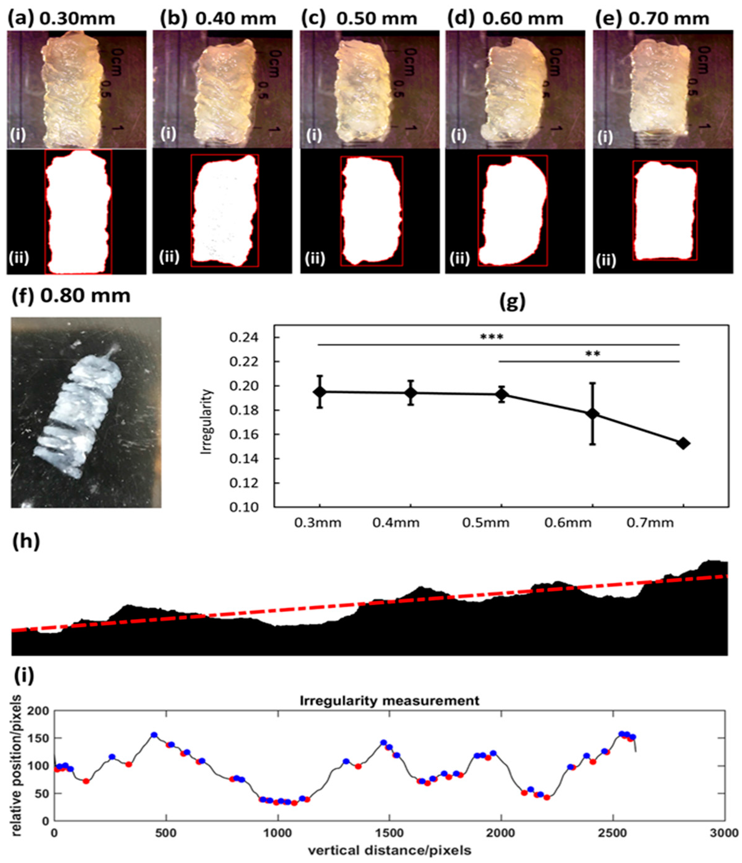
2.7. Irregularity Measuremen

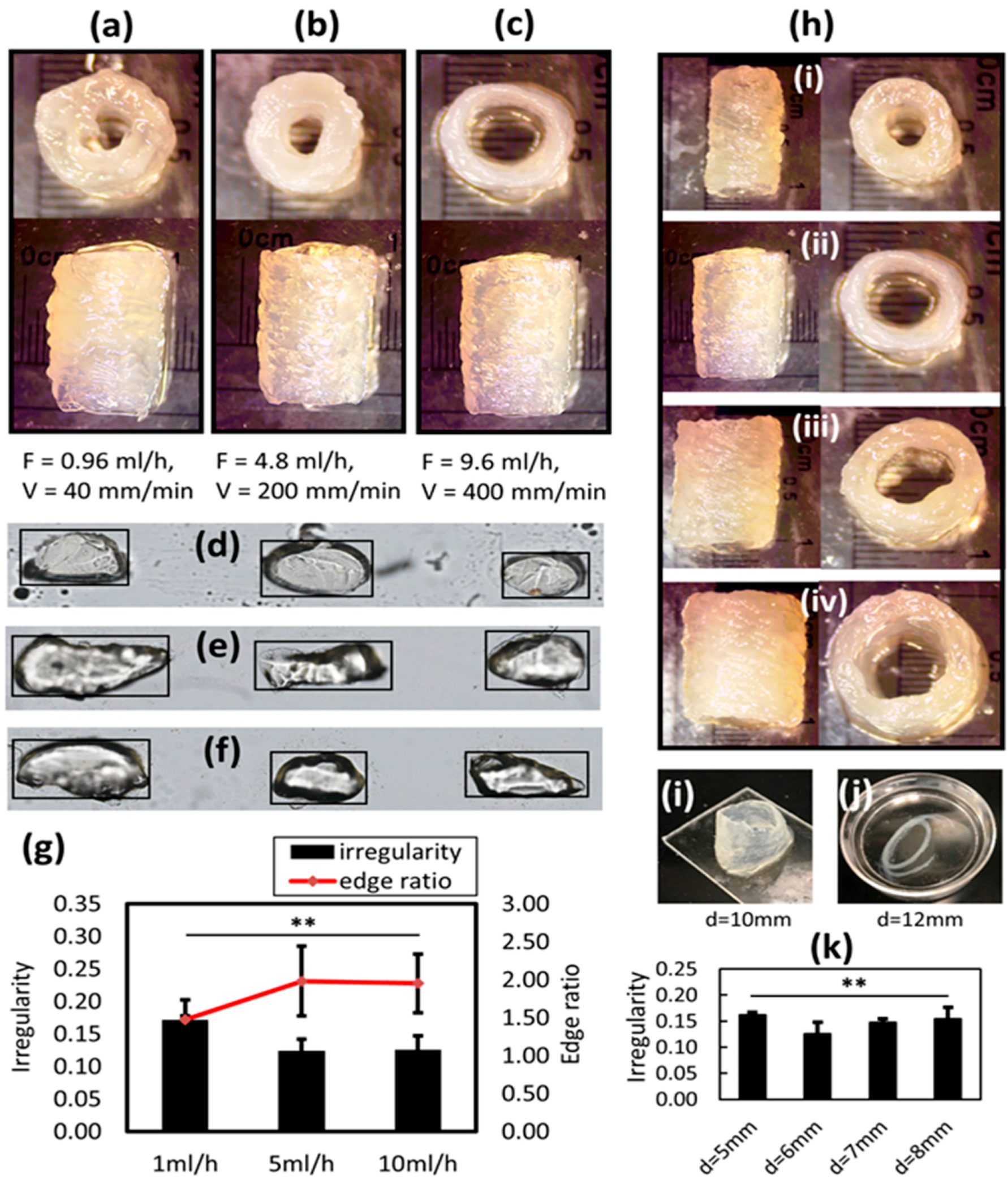
The irregularity is defined as a metric to characterize the outer surface quality of the printed tubular structure. The irregularity (or roughness) is defined as the average vertical distance between the successive local maximum and minimum points of a curve that represents a surface. To measure the irregularity of a surface (or a projected curve of a surface), a binary image of the object (e.g., Figure 5h, in which the binary image represents the arbitrary projected outline of a surface) is used. The irregularity is measured by the following algorithm: (1) By computing a fitted linear model of the outline, for example, the outline can be represented as:
y l i n e a r = a 1 x + a 0
(2) Project the outline to the fitted linear model (rotate the whole outline to eliminate the effect of global incline. Thus, the projected data can be represented as:
y p r o j = y y × s i n ( arctan | a 1 | )  
(3) The projected data will be further filtered to remove noise by using Fast Fourier Transform (FFT), and inverse-FFT algorithm, which is implemented by Matlab. A threshold is selected to filter the signals with higher frequency than the threshold, which is noise signal. After denoising, the filtered outline is represented as:
y f f t = i F F T ( F F T ( y p r o j , t h r e s h o l d ) )
(4) A set of local maximum and local minimum points are detected from the final smooth outline yfft. Successive local maximum and local minimum are set as a pair, and their absolute y direction difference is summed up and then normalized (divided by the length of measured area L). The irregularity is defined as:
i r r e g u a l r i t y = 1 L i = 1 n | y f f t ( m a x , i ) y f f t ( m i n , i ) |
in which yfft (max,i), yfft (min,i) are ith successive local max and min points.

2.8. Imaging and Data Analysis

An inverted bright field-fluorescence (IX83, Olympus) microscope is used to image the printed samples. Fluorescent images of printed cell-laden samples are processed using Cellsens, ImageJ, and Matlab to yield quantitative measurements of printed surface irregularity through fluorescent image line profile analysis. Statistical significance of measurements with a student’s t-test and one-way ANOVA is computed using GraphPad Prism 7 (GraphPad Software, La Jolla, CA, USA). Differences are considered significant as p < 0.05 (*), p < 0.01 (**), p < 0.005(***).

3. Results

3.1. Identification of Optimal Printing Temperature of Gelatin-Alginate Hydrogel

The microextrusion-based bioprinting of hydrogels is a well-established additive materials processing strategy. Although low temperature processing of hydrogels enables good shape fidelity of printed filaments, occlusion of the extruding nozzle is encountered, especially at or below ambient temperature conditions for both the hydrogel and support bath materials. Preliminary experiments demonstrate that the material fails to form a continuous filament at a prescribed temperature setting of 20 °C for the hydrogel and support bath. Another phenomenon observed during extrusion is that the extruded mass increases with a decrement in the process temperature. To probe this differential material extrusion rate phenomenon, a 10% gelatin-3% alginate blend is extruded at varying temperatures of 23 °C, 30 °C, and 37 °C, with the extrusion of DI water for comparison. Figure 3 shows that more material is extruded at lower temperatures. The setting extrusion rate is the slope of the DI water extrusion plot. The experiments indicate extrusion at higher temperature enables more accurate flowrate. Thus, in all of the experiments, gelatin-alginate hydrogel at 37 °C is used for printing based on 3 reasons: (1) Clogging issue can be significantly mitigated; (2) Extrusion flow rate can be maintained accurately; (3) Temperature is compatible for biological cell viability. In the study, all the structures are printed with 3% alginate-10% gelatin (w/v) in 4% nanoclay + 0.5% CaCl2 at a process temperature of 37 °C, which was tested as the optimal setting in a previously reported study.

3.2. Cross-Sectional Geometry Profile of Extruded Filament in Bath as a Function of Varying Travel Speeds

In parameter optimization of extrusion-based 3D printing processes, the printed filament geometry is generally a function of the printhead travel speed and material extrusion rate. For example, when printing in an air medium, the filament cross-sectional area will increase as the flow rate increases and the travel speed decreases. In the case of printing within a support bath, the aforementioned trend still holds. However, there exists qualitative differences in the observable phenomena. Due to the presence of a support bath, when the travel speed decreases, additional material is extruded and accumulates along the z-axis. The cross-section of the printed filament within a support bath assumes an oval geometry with the long axis defined in the z-direction. Figure 4 shows the side view of filaments extruded at different travel speed (160 mm/min to 400 mm/min) for a fixed extrusion flow rate (f = 4.8 mL/h). Figure 4a is the side view of filaments (laid flat) and Figure 4b–d are cross-section views of three selected filaments. The length increases as the printhead travel speed decreases. Figure 4e shows the measurements of the cross-sectional length as a function of travel speed. Schematic in Figure 4f shows the cross-sectional shape profile of the printed filament. The filament is elongated in the z-direction, as the extruding needle creates a cylindrical shear-thinning area during translation. However, the short axis of the eclipse remains stable as a function of varying travel speed. During printing multiple layer structure, the filament geometry has a significant impact on the shape quality of 3D construct. As an example, in Figure 4g,h the cross-section of the filament printed at a travel speed of 200 mm/min is selected and displayed along with the binary image of the cross-sectional view. Figure 4h is the binary contour of Figure 4g, which shows the clear cross-section of the filament. The binary contour is manually selected by tracing the contour of the cross section. To achieve an integrated print from multiple extruded layers, material overlap between successive layers is required. In Figure 4i, the schematic shows 2 filaments with an overlap that enables the fusion. The 0.70 mm is the set layer height, the 0.4 mm is the width of single filament, and 1.40 mm is the cross-sectional length of single filament. Figure 4j is the 3D model of 4 layers of helical structure with overlap of two adjacent layers. However, under certain parameters (fixed flowrate and travel speed), the layer height should be systematically studied to ensure that the successive layers are fully fused without discontinuities.

3.3. Determining the Optimal Layer Height by Printing Tubular Structures

In this paper, the layer height is defined as the prescribed gap between successive layers. The layer height parameter can be controlled by precise motion along the z-axis between printed layers. To systematically explore the optimal single layer height within a multilayered print construct using a liquid hydrogel precursor in a support bath medium, a set of tubular structures is printed to test the preservation of shape fidelity. First, by following the G-code path created by the customized toolpath generation algorithm, the tubular structure design (5 mm internal diameter and 10 mm height) shown in Figure 5 is printed and post-processed. This experiment aims to determine the effect of layer height on the printed construct shape quality under certain constant parameters (flowrate is 4.8 mL/h, travel speed is 200 mm/min, bath temperature at 23 °C). In Figure 5, the (i) of (a)–(e) are images of printed tubular structures with different layer heights. The (ii) of (a)–(e) are binary images circumscribed with a red boundary box. A decrement in the total height is observed for the 5 printed tubular structures going from (a) to (e). The smaller layer heights result in higher total heights due to the more extruded material. Layer heights equal to or larger than 0.8 mm result in disconnected layers. Figure 5f illustrates an example of a disconnected tubular structure with layer height of 0.8 mm. In this paper, a metric is defined to compute the irregularity of the printed structures, which measures the roughness of the binary image outline. In Figure 5g, the irregularity of (a)–(e) is plotted. In Figure 5h, a segment of the binary image in (c) shows the detailed edge of the printed tubular structure. The red dashed line is the fitted linear model that represents the reference line, which avoids the accumulated errors due to the image incline. Figure 5i is the plot of the projected edge curve without the effect of the image incline. The curve is de-noised by using Fast Fourier Transform (FFT) to remove high-frequency wave patterns. The blue and red dots are the detected local maximum and minimum points. The irregularity (or roughness) is defined as the average vertical distance between the successive local maximum and minimum points. The results show that the irregularity decreases as the layer height approaches an optimal value (0.3 mm to 0.7 mm). Printed structures with a layer height of 0.7 mm exhibit more uniform surface characteristics compared to its smaller layer height counterparts. However, when the layer height is set to be larger than 0.7 mm, the successively printed layers are disconnected due to large gaps. Furthermore, although the surface quality is the optimized at the larger layer height (0.7 mm), this is accompanied by weaker connections between layers. As a result, the 0.5 mm or 0.6 mm prints are preferred over the 0.7 mm print.
The previous experiments show the effect of layer heights on the structural properties under fixed conditions for flowrate, travel speed, and bath temperature. To explore other parameter’s effect on the printability of the gelatin-alginate within support bath (for example, bath temperature), more experiments have been performed. Based on the customized bath temperature control system, a higher bath temperature is set (37 °C, same as hydrogel temperature). A set of same tubular structures as in the previous section have been printed. The general trends still hold. However, as the bath temperature increases, the optimal layer height decreases. As shown in Figure 6, the different symbols represent the different qualitative designations (oversize, well-printed, weak connection, and break) of the tubular structures. It is shown that as bath temperature increases, the printed tubular structure is not significantly altered. Therefore, a lower bath temperature (22 °C) is selected for future printing due to the following reasons: (1) Less time is required to bring the bath to room temperature, which also shortens the preparation time before printing; (2) It is energy-saving to maintain the bath temperature near room temperature than at 37 °C during printing; (3) Lower bath temperature enables a more rapid gelation process, with shortening of the post-processing time after printing.

3.4. Effect of Printing Speed and Tubular Structure Diameter on Structural Irregularity and Stability

In the previous sections, an optimal setting of printing parameters is identified to ensure the good printing quality of the tubular structure. However, the printing time efficiency is also critical to the whole printing process, which is related to the printing travel speed. Firstly, in this section, the tubular structure irregularity as a function of printing speed is investigated. The optimal setting of printing parameters determined from previous sections is as follows: bath temperature at 22 °C, extrusion flowrate is 4.8 mL/h, travel speed is 200 mm/min, layer height is set as 0.5 mm (to ensure a strong connection between layers), and the hydrogel temperature is always maintained at 37 °C. When altering the travel speed, the ratio between flowrate and travel speed should be maintained at a fixed value to ensure a constant filament cross sectional area. In Figure 7a–c, the 3 pairs of flowrates and travel speeds are (a) 0.96 mL/h, 40 mm/min; (b) 4.8 mL/h, 200 mm/min, (a) 9.6 mL/h, 400 mm/min. The (a)–(c) shows the cross section view and side view of printed tubular structures at different flowrate and travel speeds. The images indicate that the irregularity is different between 3 prints. The tubular structure printed at high travel speed exhibits more uniform surface characteristics than at lower speeds. The underlying mechanism can be described as follows. Since the ratio between travel speed and the extrusion flowrate is fixed, higher travel speeds correspond to higher extrusion flowrates. Based on the fact that the gelatin hydrogel is a shear-thinning biomaterial [27], the high extrusion flowrate imparts a high shear rate of the gelatin-alginate hydrogel, which corresponds to low viscosity. During extrusion, material at a lower viscosity experiences less intermolecular internal friction, yielding an irregular printed filament surface. Similarly, the support bath is also a shear-thinning material. When the travel speed is high, the shear-thinning region experiences lower viscosities accompanied by a larger surface tension [28]. In summary, the filaments extruded at high flowrates are less viscous and exhibit a smooth surface (larger surface tension) when exiting the nozzle, and are deposited within a less viscous support bath environment with large surface tension. This mechanism results in a more uniform surface for the layered structure at high travel speeds. To explore differences in the filaments between the 3 prints, the (d)–(f) shows cross-section views with boundary boxes of filaments printed at the 3 different pairs of parameters. In Figure 7g shows a combined plot of the edge irregularity and edge ratio (defined as length/width of the boundary boxes in (d)–(f)). The larger irregularity corresponds to a lower edge ratio. When printing at a lower speed, the filament is more similar to a circle, which causes the fused filaments to be more irregular.
The other structural property investigated here is the overall structural stability. It is demonstrated that printing within a support bath medium enables complex structure fabrication. However, the designed tissue construct itself should be structurally stable. Otherwise, the structure may collapse upon extraction of the support material. To investigate this, a set of tubular structures with different diameters are printed and evaluated. The cross-sectional and side views of tubular structures printed at different diameters (5 mm–8 mm) are shown in Figure 7g,j is the irregularity plot of the printed structures in (g). Tubular structures with larger diameters are also printed, resulting in either deformed or disconnected structures. For example, the tubular structure in Figure 7i is deformed with d = 10 mm. In Figure 7j, the tubular structure with d = 12 mm is disconnected. The results show that when the diameter increases to 12 mm, the structures are not able to maintain integrity (see Figure 7j). The breakage happens during the support bath removal procedure when the overall structural stiffness is low. Therefore, this experiment indicates that, although printing within support bath enables arbitrary geometry fabrication, the structures should be carefully designed with structural stability after removal of the support bath.

3.5. Printing of Scaffold Structure within Support Bath

The mesh scaffold is the most printed structure encountered in bioprinting studies. However, when printing within a support bath, the filaments that constitute the scaffold structure are well separated, which causes the interlayer connections to be weak with low interfacial strength. In Figure 8, a mesh scaffold is printed (material is dyed green for better visualization). The Figure 8a shows the cross-section of the printed structure before removal of the support bath. Due to the presence of these layer gaps with intervening support bath material as shown in Figure 8a, any region of interlayer fusion is limited between orthogonal, overlapping filaments. Upon support material removal shown in Figure 8b,c, although the shape fidelity for a printed mesh structure with high dimensional accuracy can be preserved and the structure is able to resist the external forces encountered during post-process pipetting, the connection between layers is still weak. Upon further applied disturbance to the structure within the CaCl2 bath, although the original structure is preserved, after shaking the petri dish several times, an unraveling of the layered structure as shown in Figure 8d is observed. This is meaningful, since the printed structure will be placed within a liquid cell medium once for long-term biological study, where the disturbance is unavoidable. Hence, such layered mesh structures present a significant challenge to the maintenance of shape fidelity after post-processing. This is the reason that in this study, the most investigated parts are the tubular structures.

3.6. Bioprinting of Complex Gelatin-Alginate Tissue Constructs

In this section, a complex multi-tubular design structure with preservation of shape fidelity is printed within a support bath. The 3D model is shown in Figure 9a, in which the bifurcating structure consists of 1 main inlet tube and 4 outlet tubes that mimic the structures found in human vasculature. Figure 9b shows the toolpath that is generated based on the customized algorithm. In the absence of process parameter optimization, the printed construct shown in Figure 9d exhibits irregular surface characteristics. In contrast, the printed construct in Figure 9e reflects a stable structure with improved shape fidelity and more uniform surface characteristics. The default toolpath generated from the 3D model is not suitable for printing the gelatin-alginate material within support bath. However, the customized toolpath generation algorithm enables flexible selection of printing process parameters including flowrate, travel speed, layer height, and the printing sequence for different parts of the whole structure. The bifurcating structures that mimic the human vascular structures demonstrate complex 3D print geometries using liquid hydrogel precursors. Figure 9c is a fluorescent image of the printed single filament with bio-ink cell densities of 2 × 10⁶ cells/mL. The green dots represent live cells suspended within the gelatin-alginate hydrogel. The printing process has a minimal effect on the cell viability as observed from the relatively few cell or cell aggregates that exhibit a strong red fluorescence in Figure 9c dead cell image. The estimated viability of cells after printing and post-processing is over 99% (computed by the fluorescent intensity representing cells of live/dead images). Figure 9f–h shows the perfusion test for a single printed tubular structure. First, the nanoclay material separates the petri dish into parts without water leakage. This is assigned as a control group. Then, a tubular structure is buried within the nanoclay as shown in Figure 9g. In Figure 9h, water stained in red flow is automatically to the left side.

4. Discussion

As a current state-of-art bioprinting technique, microextrusion-based printing liquid hydrogel precursors within a supporting bath medium enable the formation of complex 3D structures. Although the essential role of a support bath in bioprinting is well-recognized, underlying structural phenomena and mechanisms are still largely unknown. In the context of emergent phenomena distinct from traditional bioprinting in air medium, control of the structural outcomes with quality design attributes requires optimization of key printing process parameters. By optimizing the bioprinting parameters for filament and tubular structures within a nanoclay support bath, the optimal printing parameters are identified and reported. First, the design and implementation of a temperature control system to the bioprinter enables the support bath temperature to be stably maintained. This temperature control system is controlled by PID controller and operated with customized software with GUI. Compared to other studies that implement nanoclay as a support bath material, the findings from this paper show that the support bath temperature has a significant effect on the formation of the printed hydrogel structures. Upon lowering the support bath temperature below room temperature (22 °C), the issue of clogging arises, which has not been reported in previous studies [14]. Furthermore, by analyzing the single filament dimension, a relationship between the filament cross-sectional long axis with extrusion flowrate and travel speed is revealed. Based on this, the optimal layer height is determined to enable solid material fusion between successively printed layers. At first, the optimal layer height for printing tubular structure is identified as 0.5 mm when the flowrate is 4.8 mL/h and travel speed is 200 mm/min. The temperature of the support bath is set near room temperature (22 °C). However, to improve printing time efficiency, different travel speeds are tested, resulting in the identification of optimal parameters for printing tubular structures with uniform surface characteristics at shorter print times. Although other state-of-art studies do consider the rheological properties as major parameters, the interplay with key process parameters has not been systematically studied, along with the effect on printed 3D structure. However, this paper highlights the key process parameters that are critical for bioprinting complex structural outcomes within a support bath medium.
To characterize the printed structure, the irregularity is proposed to measure the surface quality of the tubular structure. The irregularity serves as a quantitative metric that reveals the relationship between the investigated parameters and printed outcomes. Another property that is critical to the bioprinting structure is the resolution. It is reported herein that the single printed filament is on a millimeter scale, which is a relatively low resolution for micro-EBB technique. However, the print resolution can be significant improved by using smaller diameter nozzles. The resolution of the demonstrated bioprinted 3D tubular structures is still within the range of current state-of-art bioprinted structures. The typical printed tube has a 5~10 mm diameter when using pluronic F127 and GelMA blend [26]. The “Y” shape bifurcation structure printed using alginate within CaCl2 bath has an average diameter of 10 mm [13]. The filament diameter printed by FRESH method ranges between 160 and 260 µm; however, the variation of filament diameter is large, which means the single printed filament is non-uniform [16]. In general, although the current state-of-art bioprinted tubular structure is still at the millimeter scale, the materials, methodologies, and optimized parameters identified by each approach lay a solid foundation for the optimization of the final structural resolution in future studies.
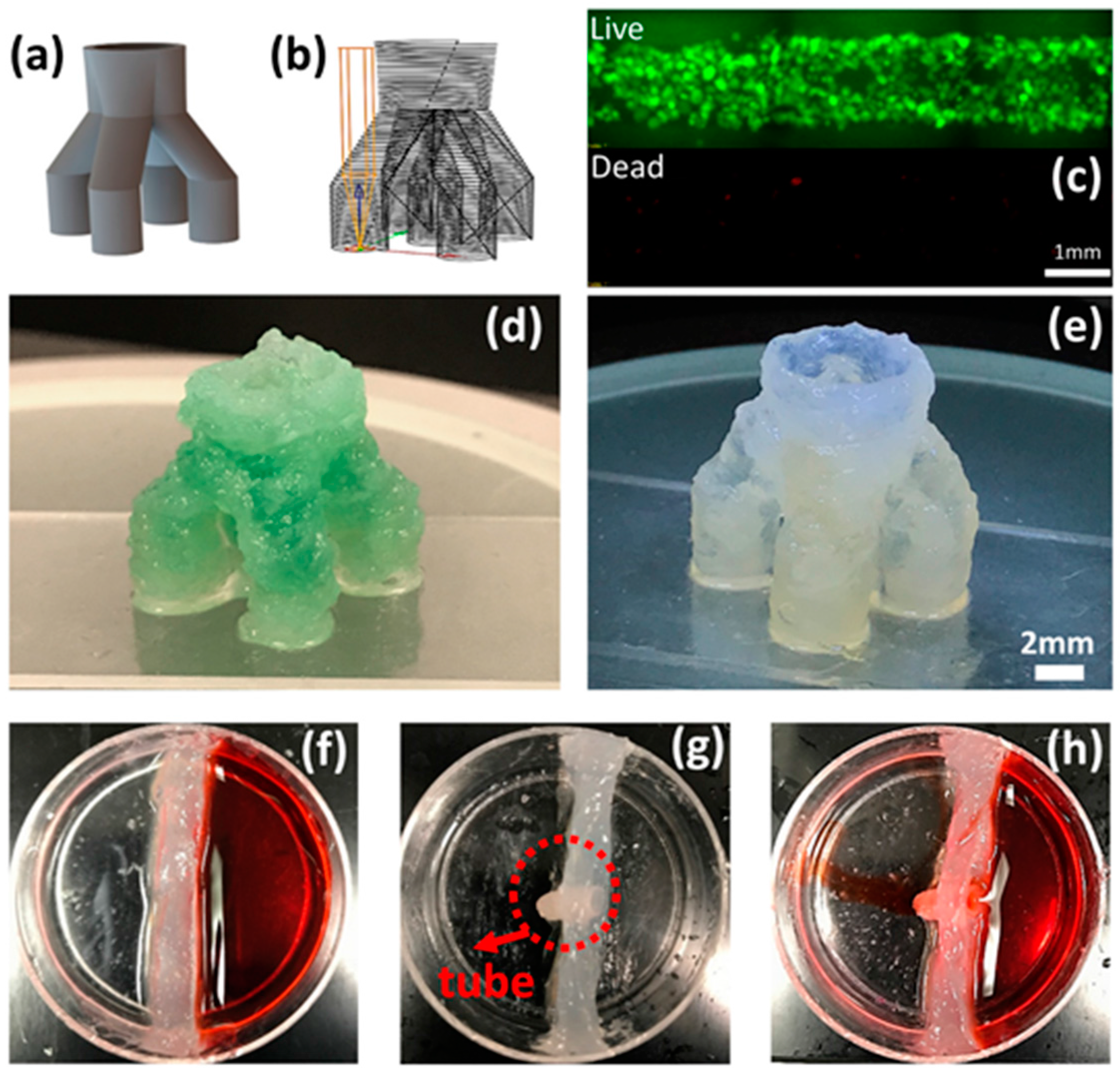
In this paper, the experimntal observations and analyses demonstrate that although printing within support bath enables fabrication of complex structure, the results indicate that the printed structure should be designed with structural stability. Otherwise, the structure will collapse after extracting the support bath. In addition, the design and printing of a bifurcating tubular structure that mimics the human vascular structures validates the parameters derived from the previous experimental results. Typically, based on the bioprinting in a support bath paradigm, a “Y” shape bifurcating print geometry is enabled, which is a planar structure [
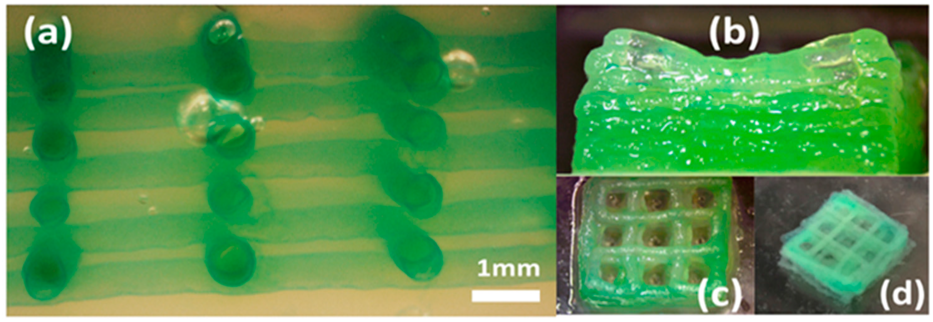
13]. However, to demonstrate increased 3D structural complexity, in this study, a customized one-to-four bifurcation toolpath is designed and printed. The printed one-to-four tubular structure can stand on the cover slide with adequate stiffness and shape fidelity. This study also investigates the shape fidelity for another prevailing bioprinting tissue structure in the mesh scaffold. The results indicate that when printing in a support bath, it is more challenging to maintain whole mesh structural integrity. The weak interfacial strength between layers is insufficient for preserving the overall shape fidelity in the context of outside disturbances. In order to further investigate some of these fundamental printability issues, ongoing research is suggested to better understand the rheological property and behavior of the support bath and bio-ink materials.

5. Conclusions

In this paper, experimental studies are conducted to investigate the printability of bifurcating tubular structures during the bioprinting process along with post-print structural outcomes. Optimal printing parameters are investigated and identified for a fast, high-quality complex bifurcating structure prints. Typically, the key parameters of bioprinting of gelatin-alginate hydrogel blend include the rheological properties of hydrogel material (tuned by material concentration and printing temperature). For bioprinting of gelatin-alginate hydrogel within a support bath medium, the material concentration of both the hydrogel and support bath are prescribed, which is optimal, based on phenomenological observations. The printability of a single filament is investigated. Therefore, in this paper, the further parametric study about other key parameters includes layer height that determines how the successive layers are fused, the printing travel speed of the shape outer surface irregularity, and the structure design that enables adequate structural stability. After all of those parameters are well understood, the final print of a bifurcation structure demonstrates the well-controlled printability of the liquid hydrogel precursor within a support bath. For future studies, the cell density within the hydrogel, as another key parameter for the bioprinted cell-laden constructs, will be systematically investigated. Also, the optimization of those process parameters has set a fundamental basis upon which the resolution of printed single filament or tubular structure can be further improved. One promising future study is to extend the printed 3D complex bifurcation structure to the micrometer feature sizes (e.g., 100–200 µm diameter), where the cells can experience an in vivo microenvironment with physiologically relevant dimensional scales.

Acknowledgments

The authors would like to thank Christie Chen from the Stevens Institute of Technology and Alan Lai from Montville Township High School for their help with the material development.

Author Contributions

Houzhu Ding developed the bioprinter, temperature control system, algorithm, and implement the experiments wrote the paper. Robert C. Chang supervised the project and paper writing.

Conflicts of Interest

The authors declare no conflict of interest.

References

  1. Dhariwala, B.; Hunt, E.; Boland, T. Rapid prototyping of tissue-engineering constructs, using photopolymerizable hydrogels and stereolithography. Tissue Eng. 2004, 10, 1316–1322. [Google Scholar] [CrossRef] [PubMed]
  2. Gebler, M.; Uiterkamp, A.J.M.S.; Visser, C. A global sustainability perspective on 3D printing technologies. Energy Policy 2014, 74, 158–167. [Google Scholar] [CrossRef]
  3. Bak, D. Rapid prototyping or rapid production? 3D printing processes move industry towards the latter. Assem. Autom. 2003, 23, 340–345. [Google Scholar] [CrossRef]
  4. Gibson, I.; Rosen, D.; Stucker, B. Additive Manufacturing Technologies: 3D Printing, Rapid Prototyping, and Direct Digital Manufacturing, 2nd ed.; Springer: New York, NY, USA, 2015. [Google Scholar]
  5. Kolesky, D.B.; Homan, K.A.; Skylar-Scott, M.A.; Lewis, J.A. Three-dimensional bioprinting of thick vascularized tissues. Proc. Natl. Acad. Sci. USA 2016, 113, 3179–3184. [Google Scholar] [CrossRef] [PubMed]
  6. Vijayavenkataraman, S.; Lu, W.F.; Fu, J.Y.H. 3D bioprinting of skin: A state-of-the-art review on modelling, materials, and processes. Biofabrication 2016, 8, 032001. [Google Scholar] [CrossRef] [PubMed]
  7. Ng, W.L.; Wang, S.; Yeong, W.Y.; Naing, M.W. Skin Bioprinting: Impending Reality or Fantasy? Trends Biotechnol. 2017, 34, 689–699. [Google Scholar] [CrossRef] [PubMed]
  8. Ringeisen, B.R.; Spargo, B.J.; Wu, P.K. Cell and Organ Printing; Springer Science & Business Media: Dordrecht, The Netherlands, 2010. [Google Scholar]
  9. Murphy, S.V.; Atala, A. 3D bioprinting of tissues and organs. Nat. Biotechnol. 2014, 32, 773–785. [Google Scholar] [CrossRef] [PubMed]
  10. Pfister, A.; Landers, R.; Laib, A.; Hübner, U.; Schmelzeisen, R.; Mülhaupt, R. Biofunctional rapid prototyping for tissue-engineering applications: 3D bioplotting versus 3D printing. J. Polym. Sci. Part A Polym. Chem. 2004, 42, 624–638. [Google Scholar] [CrossRef]
  11. Jang, J.; Park, H.-J.; Kim, S.-W.; Kim, H.; Park, J.Y.; Na, S.J.; Kim, H.J.; Park, M.N.; Choi, S.H.; Park, S.H.; et al. 3D printed complex tissue construct using stem cell-laden decellularized extracellular matrix bioinks for cardiac repair. Biomaterials 2017, 112, 264–274. [Google Scholar] [CrossRef] [PubMed]
  12. Pati, F.; Jang, J.; Ha, D.-H.; Won Kim, S.; Rhie, J.-W.; Shim, J.-H.; Kim, D.-H.; Cho, D.-W. Printing three-dimensional tissue analogues with decellularized extracellular matrix bioink. Nat. Commun. 2014, 5, 3935. [Google Scholar] [CrossRef] [PubMed]
  13. Tabriz, A.G.; Hermida, M.A.; Leslie, N.R.; Shu, W. Three-dimensional bioprinting of complex cell laden alginate hydrogel structures. Biofabrication 2015, 7, 045012. [Google Scholar] [CrossRef] [PubMed]
  14. Jin, Y.; Chai, W.; Huang, Y. Printability study of hydrogel solution extrusion in nanoclay yield-stress bath during printing-then-gelation biofabrication. Mater. Sci. Eng. 2017, 80, 313–325. [Google Scholar] [CrossRef] [PubMed]
  15. Jin, Y.; Compaan, A.; Chai, W.; Huang, Y. Functional Nanoclay Suspension for Printing-Then-Solidification of Liquid Materials. ACS Appl. Mater. Interfaces 2017, 9, 20057–20066. [Google Scholar] [CrossRef] [PubMed]
  16. Hinton, T.J.; Jallerat, Q.; Palchesko, R.N.; Park, J.H.; Grodzicki, M.S.; Shue, H.-J.; Ramadan, M.H.; Hudson, A.R.; Feinberg, A.W. Three-dimensional printing of complex biological structures by freeform reversible embedding of suspended hydrogels. Sci. Adv. 2015, 1. [Google Scholar] [CrossRef] [PubMed]
  17. Hinton, T.J.; Hudson, A.; Pusch, K.; Lee, A.; Feinberg, A.W. 3D Printing PDMS Elastomer in a Hydrophilic Support Bath via Freeform Reversible Embedding. ACS Biomater. Sci. Eng. 2016, 2, 1781–1786. [Google Scholar] [CrossRef] [PubMed]
  18. Cui, X.; Boland, T.; D’Lima, D.D.; Lotz, M.K. Thermal Inkjet Printing in Tissue Engineering and Regenerative Medicine. Recent Pat. Drug Deliv. Formul. 2012, 6, 149–155. [Google Scholar] [CrossRef] [PubMed]
  19. Ozbolat, I.T.; Yu, Y. Bioprinting Toward Organ Fabrication: Challenges and Future Trends. IEEE Trans. Biomed. Eng. 2013, 60, 691–699. [Google Scholar] [CrossRef] [PubMed]
  20. Kang, H.W.; Lee, S.J.; Ko, I.K.; Kengla, C.; Yoo, J.J.; Atala, A. A 3D bioprinting system to produce human-scale tissue constructs with structural integrity. Nat. Biotechnol. 2016, 34, 312. [Google Scholar] [CrossRef] [PubMed]
  21. Billiet, T.; Gevaert, E.; De Schryver, T.; Cornelissen, M.; Dubruel, P. The 3D printing of gelatin methacrylamide cell-laden tissue-engineered constructs with high cell viability. Biomaterials 2014, 35, 49–62. [Google Scholar] [CrossRef] [PubMed]
  22. Starly, B.; Shirwaiker, R. 3D Bioprinting Techniques BT—3D Bioprinting and Nanotechnology in Tissue Engineering and Regenerative Medicine; Academic Press: Cambridge, MA, USA, 2015. [Google Scholar]
  23. Campos, D.F.D.; Blaeser, A.; Weber, M.; Jäkel, J.; Neuss, S.; Jahnen-Dechent, M.; Fischer, H. Three-dimensional printing of stem cell-laden hydrogels submerged in a hydrophobic high-density fluid. Biofabrication 2013, 5, 015003. [Google Scholar] [CrossRef] [PubMed]
  24. Highley, C.B.; Rodell, C.B.; Burdick, J.A. Direct 3D Printing of Shear-Thinning Hydrogels into Self-Healing Hydrogels. Adv. Mater. 2015, 27, 5075–5079. [Google Scholar] [CrossRef] [PubMed]
  25. Kolesky, D.B.; Truby, R.L.; Gladman, A.S.; Busbee, T.A.; Homan, K.A.; Lewis, J.A. 3D Bioprinting of Vascularized, Heterogeneous Cell-Laden Tissue Constructs. Adv. Mater. 2014, 26, 3124–3130. [Google Scholar] [CrossRef] [PubMed]
  26. Suntornnond, R.; Tan, E.Y.S.; An, J.; Chua, C.K. A highly printable and biocompatible hydrogel composite for direct printing of soft and perfusable vasculature-like structures. Sci. Rep. 2017, 7, 16902. [Google Scholar] [CrossRef] [PubMed]
  27. Liu, W.; Heinrich, M.A.; Zhou, Y.; Akpek, A.; Hu, N.; Liu, X.; Guan, X.; Zhong, Z.; Jin, X.; Khademhosseini, A.; et al. Extrusion Bioprinting of Shear-Thinning Gelatin Methacryloyl Bioinks. Adv. Healthc. Mater. 2017, 6, 1601451. [Google Scholar] [CrossRef] [PubMed]
  28. Pelofsky, A.H. Surface Tension-Viscosity Relation for Liquids. J. Chem. Eng. Data 1966, 11, 394–397. [Google Scholar] [CrossRef]
Figure 1. Temperature control system: (a) The control box; (b) the printing head; (c) configuration of thermocouple, heating element, and support bath; (d) the diagram of the temperature control system.
Applsci 08 00403 g001
Figure 2. The PID control flowchart for controlling the bath temperature: (a) The flowchart shows the measurement and control procedure for the bath temperature; (bd) shows the “Real Time Temperature Monitor” GUI captured at three different time points. The temperature increases gradually and stabilizes at the target temperature.
Applsci 08 00403 g002
Figure 3. The effect of process temperature on extrusion rate of gelatin-alginate (GA) with comparison to DI water.
Applsci 08 00403 g003
Figure 4. The cross-section geometry of the printed filament within a support bath medium with travel speed from 160 mm/min–400 mm/min, at flowrate of 4.8 mL/h: (a) the image of the filaments (laid flat, side view); (bd) cross section view of three selected filaments. The length increases as the travel speed decreases; (e) measurements of the cross section length as a function of travel speed; (f) schematic shows the cross section of printed filament. The filament is elongated in z direction due to the slow travel speeds; (g) the cross section of the filament printed at travel speed of 200 mm/min; (h) binary image of the cross section view; (i) the schematic shows 2 filament with overlap that enables the fusion; (j) the 3D model of a 4 layers of helical structure with overlap of two adjacent layers.
Applsci 08 00403 g004
Figure 5. The effect of layer height on the printed construct shape quality: (ae) The (i) of (ae) are images of printed tubular structures with different layer heights (flowrate of 4.8 mL/h and travel speed of 200 mm/min), and (ii) of (ae) are binary images with boundary box; (f) disconnected tubular structure with layer height of 0.8 mm; (g) the irregularity of the outer surface of the printed tube; (h) binary image segment shows the details of the outer surface of the printed tubular structure, red line is the fitted linear model representing the reference line; (i) the projected and filtered surface wave with detected local maximum and minimum points.
Applsci 08 00403 g005
Figure 6. Effect of support bath temperature on the printed tubular structure quality. (a) The plot of the printed tubular structures quality as a function of support bath temperature and layer height; (b) Color image of the 3 types (“oversize”, “well-printed”, “weak connection”) tubular structures; (c) Color image of “break” tubular structure.
Applsci 08 00403 g006
Figure 7. Effect of support travel speed and tubular structure diameter on the printed tubular structure quality; (ac) cross-sectional and side views of printed tubular structures at different flowrates and travel speeds; (df) cross sectional view with boundary boxes of filaments printed at the 3 different parameter sets; (g) combined plot of the edge irregularity and edge ratio (defined as length/width of the boundary boxes in (df); (h) the cross-sectional and side views of tubular structures printed at different diameters (5 mm–8 mm); (i) tubular structure is deformed with d = 10 mm; (j) tubular structure is disconnected between layers with d = 12 mm; (k) irregularity plot of the printed structures in (g).
Applsci 08 00403 g007
Figure 8. Mesh scaffold printing with weak interfacial connections: (a) The cross section of the printed structure before removal of the support bath; (b) side view of the printed mesh structure after removal of support bath; (c) top view of the printed mesh structure after removal of support bath; (d) unraveling of the layered structure within CaCl2 bath due to the disturbance caused by shaking the petri-dish.
Applsci 08 00403 g008
Figure 9. The design and print of a multi-tubular hydrogel structure: (a) the 3D CAD model of the bifurcation structure; (b) customized toolpath; (c) live/dead cell fluorescent image of single filament with cell-laden bio-ink; (d) the printed structure without using optimal parameters, yielding irregular surface; (e) the printed structure using optimal parameters, yielding a smoother surface and enhanced shape fidelity; (f) Nanoclay separates the petri dish to 2 parts without water leakage; (g) Tubular structure is buried within nanoclay; (h) Water stained in red flow automatically to the left side.
Applsci 08 00403 g009
Table 1. Printing process parameters.
ParametersValues
Bio-ink temperature23 °C, 31 °C, 37 °C
Support bath temperature22 °C , 37 °C
Travel speed160, 200, 240,…, 400 (mm/s)
Layer height0.3, 0.4,…, 0.8 (mm)
Extrusion flowrate0.96 mL/h, 4.8 mL/h, 9.6 mL/h
Tube diameter5, 6,…, 12 (mm)

