Abstract
Nowadays, more and more complex methods of signal modulating and processing are actively used for organizing underwater acoustic communication with and between submerged mobile vehicles due to harsh underwater conditions. In this research, the method that is based on multi-frequency signals forming (OFDM) with the constant envelope is applied to the problem. It is based on multi-frequency FM-OFDM signals forming with Quadrature Phase Shift Keying (QPSK) modulated subcarriers and FM spectrum spreading coefficients of 1, 2, 4, and 10. The proposed solution was modeled in a software simulator, which implements a noisy underwater acoustic multipath channel, changing the bit error rate (BER) from 0.15 to 10−3. In addition, it was tested during the full-scale data transmission experiments at 25 km distance using a low frequency (400 Hz) underwater acoustic apparatus under conditions of strong impulse noises and quasi-non-stationary channel. The results of in-situ experiments were similar to the ones that were obtained during the simulation.
1. Introduction
Multifrequency methods of signal modulation, such as OFDM, gained a lot of attention not only in the radiocommunications, but in underwater acoustic communications (UAC) as well. Current popularity of such methods in hydro acoustic communications relates to possibilities of the effective usage of frequency resource of the underwater acoustic channel. The growing needs of autonomous underwater vehicles (AUV) capabilities for the World Ocean research and exploration demand the implementation of effective communication systems in regard to throughput and noise-sustainability, which are used for underwater navigation.
AUVs and other surface/underwater objects of marine mission maintenance (vessels, buoys, autonomous surface vehicles (ASV), and stationary bottom underwater stations) demand the organization of proper underwater communication and navigation under conditions of underwater environment with highly unstable parameters [1,2]. Usually, data transmission rate is not the main factor and its performance of a couple of tens/hundreds bits per seconds is enough for navigation and telemetry transmission purposes. To organize a connection with AUV the preferred throughput must be an order higher, in Kbit/s; and, under such conditions as alternating acceleration of underwater and surface vehicles, frequency and time selective signal fading, the presence of high power impulse noises, and Doppler frequency shifts. In that case, one of the key parameters defining the achievable throughput is the total bandwidth of receiver and transmitter paths. The defining aspect of this issue is performance of the transmitting acoustic antenna and the underwater channel itself with its strongly marked non-uniform frequency transfer response.
There are several main methods of Doppler shift compensation in OFDM-based underwater acoustic communication systems. One of them is exploiting of Doppler-resilient signals (for example with linear frequency modulation) as a preamble and a postamble of OFDM signal to detect changes in its length [3].
Also, some a priori vulnerable for Doppler effects signals (like, M-sequences, OFDM test signals, etc.) can be used as a preamble for OFDM symbol. They are used in combination with a bank of matched filters in the receiver, and each of them are tuned for predetermined value of Doppler shift [4,5]. Responses of filter bank allows for estimating the influence (vector) and value of frequency shift and to compensate it. For example, in the paper [6], simulation of UAC system utilizing pseudo-noise sequences as a preamble were conducted resulting low error rate (BER < 0.01) with peak frequency shift of 40 Hz on central frequency of 12 kHz.
Other way of increasing of Doppler shift resistance is adding of null or pilot sub-carriers into OFDM packet. Such approach was used in [7], where authors were able to reach 1% BER while maximum Doppler shift (for the highest sub-carrier) was 13.36 Hz, which was more than sub-carriers frequency spacing (11.71 Hz). In addition, all of these methods can be used in together in different combinations, but adding of each new feature almost always results in a degradation of data throughput.
Existing modern hydro acoustic communication equipment can be divided into three categories ,according to the effectiveness of signal processing: with high spectral efficiency (from 2 to 4 bit/s/Hz) exploiting parallel frequency division of information symbols (OFDM) and M-QAM methods; with moderate spectral efficiency (from 0.1 to 1 bit/s/Hz) based on sequential frequency division (S2C, etc.) [8,9]; and low frequency efficiency (0.1 bit/s/Hz and lower) based on direct-sequence spread spectrum (DSSS) [10]. Theoretically, the specified spectral efficiency of the system with working frequencies up to 60 kHz allows to create relatively high-speed underwater communication links (up to tens of Kbit/s), but this throughput is achievable only if the channel parameters are stable and the transmitter/receiver are tuned properly using up-to-date complex approaches. However, the real data rate depends on a number of factors, which have a cumulative influence: utilized media access control (MAC) protocol, reverberation time, signal-to-noise ratio (SNR), impulse noises, relative speed of the transmitter, and receiver movement, etc. A multitude of such factors change the real data throughput from hundreds of bit/s to units of Kbit/s.
The research was aimed at designing and testing of the multi-carrier modulation technique tolerant to the aggregation of the above mentioned parameters, but providing a relatively high data throughput in UAC systems. That goal requires solving problem of implementation of algorithms, operating without regular channel state estimation and multiple transmissions of test packets (signals). It is especially important for mobile communicating objects for saving time resource and increasing the total data rate. The resistance of the system for Doppler frequency shift is also vital, as well as the possibilities of utilization of non-complex algorithms of reduction of high-power impulse noises in receiving a path and supporting of non-coherent mode of the receiver.
In this work, we present an underwater acoustic communication system exploiting frequency modulated multi-frequency signals (FM-OFDM) with QPSK modulation of sub-carriers. In the first section of the paper the features of multi-frequency signal forming with the angle modulation and demodulation algorithm are presented and advantages of the proposed solution in non-coherent detection of signal carrier and Doppler shift resilience are described. Analytical expressions for BER estimation while using QPSK modulation of OFDM subcarriers are shown along with the features of digital frequency demodulator operation in conditions of a multi-path channel.
In the second part, the analysis of effectiveness of the proposed FM-OFDM-QPSK method (with the spread spectrum coefficients of 1, 2, 4, and 10) is conducted. Analytical expressions for BER and the results of numerical modeling of BER performance for different multipath channel responses are presented. In the third part the results of full-scale experiments with the proposed method at 25 km distances using low frequency (400 Hz) underwater acoustic equipment are shown and are analyzed along with the additional numerical simulation with strong Doppler shift. The dynamic of amplitude-frequency characteristics of underwater acoustic channel during experiments, channel impulse responses are presented. Values of BER for FM-OFDM-QPSK (with spread spectrum coefficient of 1, 2, 4, and 10) are obtained and are similar to the ones that were obtained during simulation.
2. The Features of FM-OFDM Communications Scheme
A great number of modern researches in the field of underwater digital communication are dedicated to methods utilizing the orthogonal frequency division multiplexing [11]. This direction was adopted from radio communication systems, the majority of which are based on OFDM nowadays. In radio communications OFDM is implemented as a standard, providing high data throughput and high resistance to multipath signal propagation. On the other hand, a wide variety of OFDM underwater acoustic communication solutions found in the literature show that an active scientific search is being made to find ways of saving natural advantages of OFDM in harsh conditions of the underwater environment [12].
The demand for high-precision underwater navigation and reliable high-speed communication is growing fast with active implementation of robotics in different aspects of World Ocean research and exploration. Undoubtedly, this demand is linked with the organization of communication in conditions of high mobility of underwater and surface vehicles participating in the mission. Exactly in mobile systems of underwater acoustic communication is where the OFDM method shows vulnerability. To fight this problem, different methods of signal pre-correction in combination with the noise-sustainable coding are used to reach reasonable ratio of data-rate-to-noise-sustainability. One of the most effective modes of reception in non-stationary channels is the non-coherent reception of carrier signal. The usage of frequency modulation for OFDM signals makes it possible to implement non-coherent detection techniques, provides sustainability for Doppler shifts, and tremendously reduces Peak-to-Average ratio (PAPR) of the OFDM signal [13].
To form an FM-OFDM signal, the model of multifrequency stochastic signal with the normal distribution to image part of OFDM symbol is accepted. The OFDM signal representation after rationing has a following form:
where is the spacing between OFDM sub-carriers, is the information symbol (of the nth frequency domain), and N is the number of subcarriers [14].
FM-OFDM signal for carrier frequency and for the index of frequency modulation can be represented by the following expression:
where is the signal amplitude.
Forming FM signal in the transmitter and its demodulation in the receiving path are conducted by using the quadrature processing in digital signal processor (DSP). Expression (2) is presented as a sum of two quadrature components , where can be set to 1 V, and the frequency deviation is determined by OFDM signal bandwidth and frequency modulation index . Here, quadrature low frequency signals I and Q: , . During demodulation by quadrature processing and filtration signals and are formed in channels I and Q:
So, for the demodulation of the FM it is necessary to calculate the phase of the received pair of quadrature components and to differentiate the achieved expression with respect to time: . Taking into attention that the expression of demodulation algorithm simplifies [14]:
Let us consider the reception of FM-OFDM signal with an arbitrary initial phase:
Taking into attention that integral (or low pass filtering) of the product equals to null and and equals to 0.5, and accepting that functions и can be considered as a slowly varying the above mentioned expressions can be simplified to:
Using non-coherent quadrature detection with the arbitrary initial phase of carrier frequency , according to the expression (3), we can get an identical signal on the demodulator output:
Likewise, the influence of the Doppler frequency shift can be observed by substituting in the above mentioned expressions. During the demodulation, according to the expression (3), the following expression can be obtained:
In that case, the frequency shift equals to the presence of the steady component in OFDM signal.
Also, the strong resistance of this demodulation method to the Doppler carrier frequency shift can be noted. Usually, such distortion leads to the presence of a constant component in demodulated signal, which, however, has no effect on the Fast Fourier Transform (FFT) of the OFDM symbol image part.
To increase the spectral efficiency of communication system it is rational to use the M-QAM modulation of OFDM subcarriers. However, the implementation of such methods is restricted by such a significant factor as instability of underwater acoustic channel parameters, especially if communicating objects are mobile. This phenomenon leads to substantial variability of signal amplitudes on the symbol transmission time interval, which forces the use of differential methods of data transmission. On the other hand, a bipolar orthogonal system of symbol transmission (QPSK) can be a compromise between the data rate and noise-sustainability. This approach can help in reducing the amplitude ambiguity during the symbol decoding in such conditions.
Using the QPSK modulation of OFDM subcarriers, the expression (2) looks as follows:
where is the complex information QPSK symbol on the nth OFDM subcarrier.
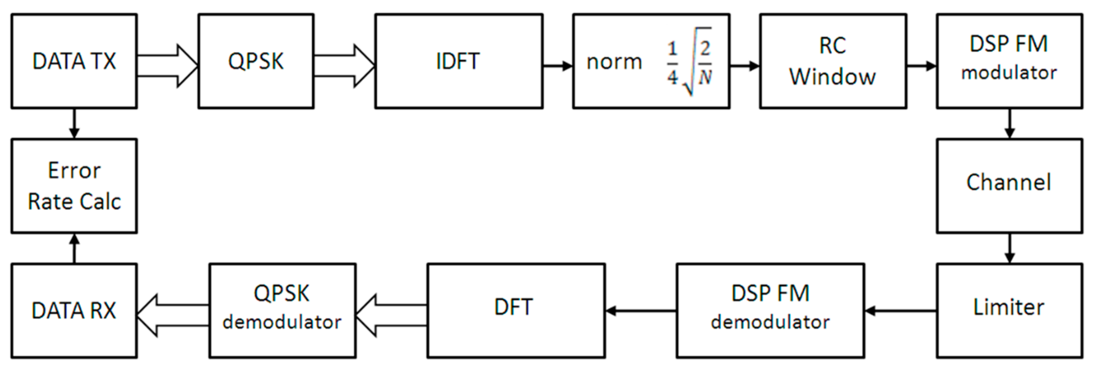
The structural scheme of transmitting and receiving process is demonstrated in Figure 1. In this structure, the system of high-frequency synchronization is missing and the receiving path is implemented using a non-coherent scheme. For the frame synchronization of OFDM-QPSK symbols, the pseudo-random binary sequences are used in combination with a matched filter on the receiver.
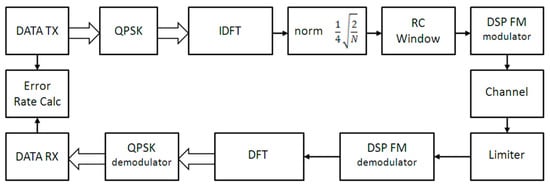
Figure 1.
The structural scheme of the orthogonal frequency division multiplexing in combination with additional frequency modulation (FM-OFDM-QPSK) transmitting-receiving processes.
Analyzing the noise-sustainability of the FM-OFDM-QPSK method, it is necessary to estimate the error probability under AWGN channel with spectral power density .
Average power in the bandwidth of modulating multi-frequency signal is . When the power of harmonic noise of frequency ω is low, the law of phase changing can be expressed as: where is distortion amplitude. In this case, the law of frequency deviation is described by expression , taking into attention that .
In this case low amplitude additive harmonic distortion results in the parasitic angle modulation. The frequency modulation function, depending on the distortion frequency and the distortion amplitude on the output of demodulator, is equal to .
The average power of this function equals to the power accounted on the frequency range of : , where , then .
The energy spectrum of the distortion is uniform in the bandwidth from to and equal to the null out of this range, so .
The noise power in the modulating signal bandwidth can be achieved by substituting variable with . That allows for finding the SNR in the modulating signal bandwidth .
Taking into attention that SNR on the input of FM demodulator is defined by the expression: ; and expression for BER for OFDM-QPSK modulated signals can be expressed as: , where ., then, after simplification, we can get an expression:
Further, it is necessary to consider operational feature of digital frequency demodulator according to the expression (3) under influence of multipath components at the input of the detector.
In the general case, the FM-OFDM signal propagating through a non-stationary multi-path communication channel and arriving at the receiver input can be expressed as:
where , , are time-variant magnitude, signal delay, frequency, and phase shifts of ray k from ray ensemble L, correspondingly. Substituting expression (4) in (6) and solving it according to (3) we get a complex relationship with a large number of variables, which is easier to solve using the numerical form. Let us take a closer look at the stationary two-ray channel model passing a signal (4).
For the propagation model with one reflection component with amplitude of () and delay of , the channel impulse response will be described by expression . After substituting it to the expression (3) and some transformations, we obtain the following expression:
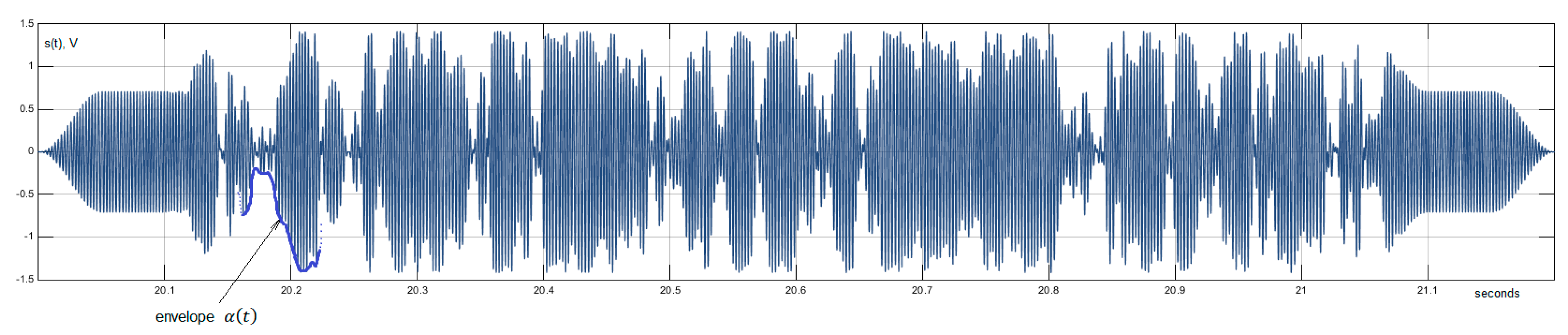
Here, it can be seen that the demodulated OFDM signal is exposed to a parasitic amplitude modulation when FM detector has a direct and strong delayed signal, which leads to the corruption of OFDM subcarriers’ orthogonality. The fragment of FM-OFDM symbol under the influence of strong reflected component of the signal () is shown in Figure 2. In that case, the sum of the direct and reflected signal is modulated on amplitude by the function :
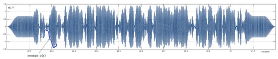
Figure 2.
A fragment of the FM-OFDM symbol in the presence of a strong reflected signal component.
For the substantial weakening of this effect the adaptive amplitude clipper must be implemented at the FM demodulator input. Some numerical BER estimations were made under conditions of different multipath propagation profiles, depending on the saturation parameter taking into account the fundamental analytical difficulties in determining the optimal level of signal clipping. In the Table 1 below BER values for FM-OFDM-QPSK under convolution with multipath channel profiles with frequency characteristics and and depending on saturation parameter are presented. The parameters of the numerical model were chosen similar to marine experiments conditions; the center frequency was equal to 400 Hz, OFDM-QPSK bandwidth—100 Hz, and sampling frequency—8 kHz.

Table 1.
BER values for FM-OFDM-QPSK depending on the saturation parameter
Using this method, the input signal amplitude clipping at the levels corresponding to γ = [0.3...0.5] BER values are minimal. Also, an effective clipping of strong impulse noises, which are usual for shallow and noisy aquatic areas, is implemented in this method.
3. Numerical Experiments with FM-OFDM-QPSK in Multipath Channels
In this part of the paper, the analysis of effectiveness of the FM-OFDM-QPSK mode (with the spread spectrum coefficient of 1, 2, 4, and 10) with precise frame synchronization of OFDM symbols based on maximum amplitude of the matched filter response on pseudorandom sequence (PRS), which is located in front of data packet, is presented. The results of numerical modeling of BER performance for different multipath channel responses are presented.
To estimate the effectiveness of the work of FM-OFDM-QPSK system numerical models with different spread spectrum the coefficients were designed. The parameters of numerical models were adapted to experimental underwater acoustic equipment (central frequency of 400 Hz, total bandwidth 200 Hz) to simplify the following sea trials. Models for each spread spectrum coefficient of 1, 2, 4, and 10 were designed. The parameters of designed models are presented in Table 2, where is the time guard interval and is the data transmission rate. The time guard interval between OFDM symbols was chosen based on previously conducted experiments at the distances more than 100 km aimed at the estimation of the channel impulse response and data transmission at 400 Hz frequency in current aquatic area, and it is equal to 200 ms [15,16].
Table 2.
The parameters of FM-OFDM-QPSK numerical models for the central frequency of 400 Hz and bandwidth of 200 Hz.
The ratio of the duration of multi-frequency symbol to the time guard interval was chosen equal to 5 for each mode, where . When considering the modes of FM-OFDM-QPSK with spread spectrum, it is expected to observe the decrease of the spectral efficiency calculated by formula .
However, one of the advantage of the systems exploiting parallel frequency multiplexing of information symbols (OFDM) is the slower decrease of the spectral efficiency depending on the value of the time guard interval compared to methods based on sequential frequency multiplexing, where the effectiveness of spectral utilization is estimated by the expression [8,9]. Also, this advantage of OFDM systems appears when comparing it to other known modulation methods. For example, mode K10 (bandwidth of 17 bit/s) reached BER < 10−2 in channel with AWGN (SNR = 0 dB). In that case, the protection from reverberation distortions with the length of 200 ms was provided. When comparing FM-OFDM to DSSS on similar SNR in the 200 Hz bandwidth, it can be noted that the DSSS system with chip speed of 100 chip/s and zero guard intervals reaches only 5 bit/s of effective information speed for the code of 20 elements not providing proper noise-sustainability due to short code.
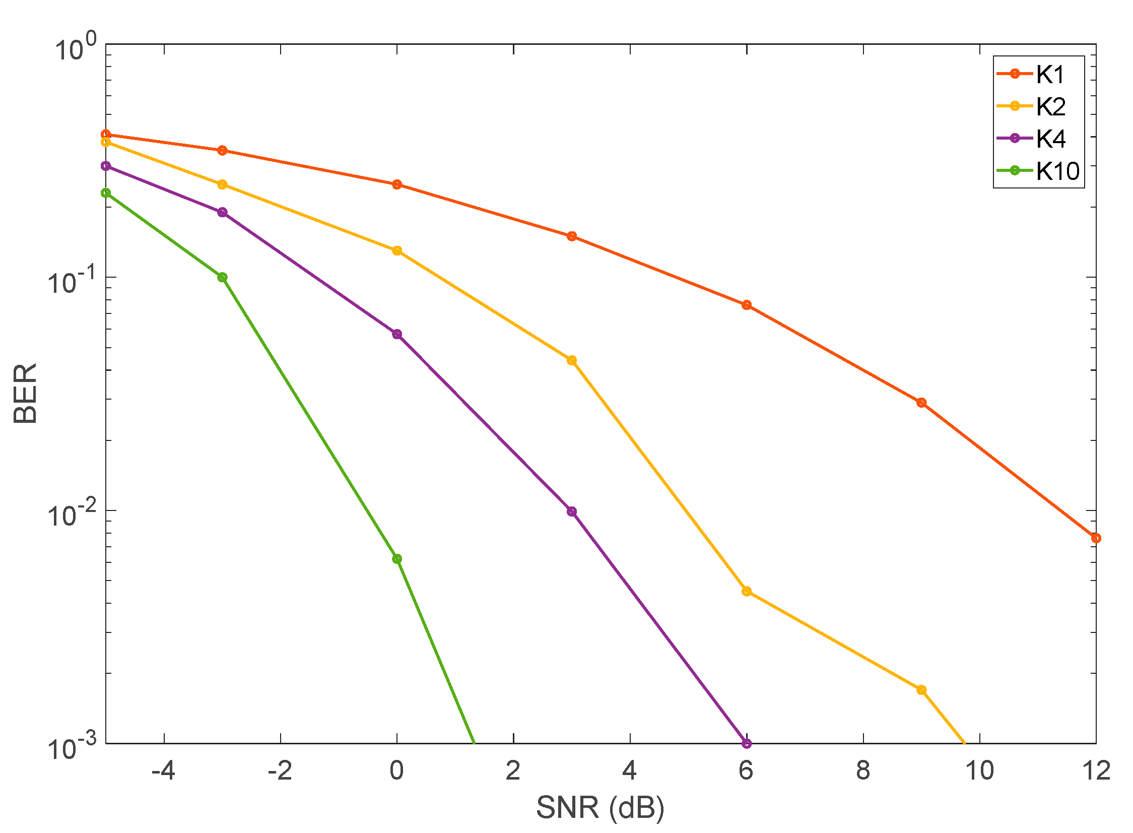
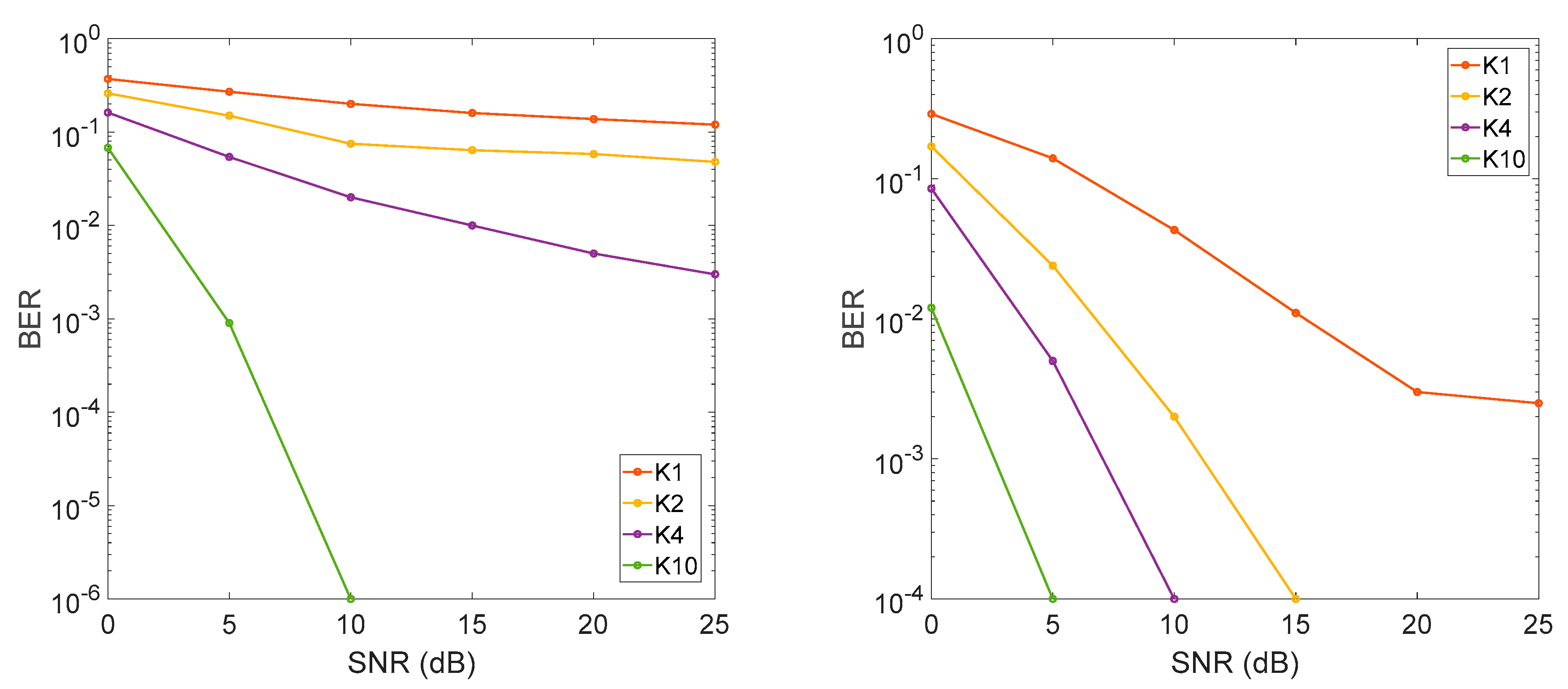
For the modes K1, K2, K4, and K10 (depending on the spectrum spread coefficient ) numerical simulations were made to estimate the dependence of total BER from SNR under AWGN on the input of FM demodulator. The BER values were measured without any noise-sustainable coding. The results of the modelling are presented in Figure 3.
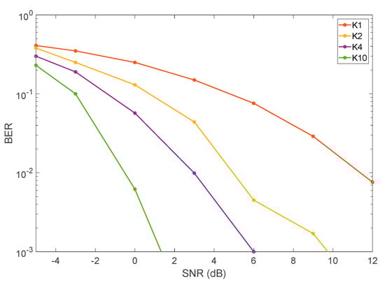
Figure 3.
Results of the bit error rate (BER) (signal-to-noise ratio (SNR)) ratio modeling under AWGN conditions.
The character and values of BER (SNR) for chosen modes correspond with analytical expressions, according to the expression (5) [13]. To evaluate the noise-sustainability of the method under study, a number of multipath channel impulse responses corresponding to the underwater acoustic channel were chosen [17].
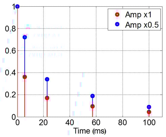
Figure 4.
Test channel responses of the underwater acoustic channel.
Also, for all four modes, the numerical simulations were conducted to evaluate BER (SNR) ratio under the contraction of transmitting signals with channel responses and . The results of simulation are presented in Figure 5.
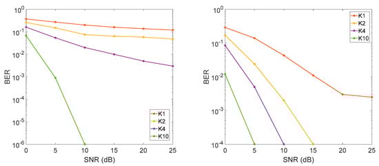
Figure 5.
BER of SNR performance acquired during the numerical simulation for channel responses .
These values show the increase of the noise-sustainability of the system with increasing of the spectrum spread coefficient of FM-OFDM under relatively complex multipath responses of underwater acoustic communication channel. Determining the optimal mode of the work for the real condition relates to the compromise between system spectral efficiency and noise-sustainability. With the channel error being lower than 10−1…10−2, it is possible to get decent values of BER using effective methods of noise-sustainable coding [18].
4. Marine Experiments and Numerical Estimations of Doppler Shift Sustainability
Marine experiments were conducted in collaboration with the Laboratory of acoustical tomography of Il’ichev Pacific Oceanological Institute FEB RAS in the July 2017 in the Peter the Great Bay in the Japanese (Eastern) Sea. The transmitting complex was located on the shore, and the transmitting antenna with the frequency band of 300–500 Hz was located on 1 m above the bottom and 150 m away from the sea shore. Preliminary, the estimations of vertical sound speed profile in the reception point were made and the depth-depended distribution of temperature was studied. Under conditions of summer hydrology (negative gradient of the sound speed profile) acoustical energy of the signal was focused in the near-bottom channel on the shelf zone with gradual slipping on the axis of deep underwater acoustic channel. That effect can be used for the conducting of long-haul underwater acoustic communication [19].
The signal was received on the ship at the distance of 25 km using a stationary hydrophone that was located near the sea bottom, when the total depth in reception point was around 100 m.
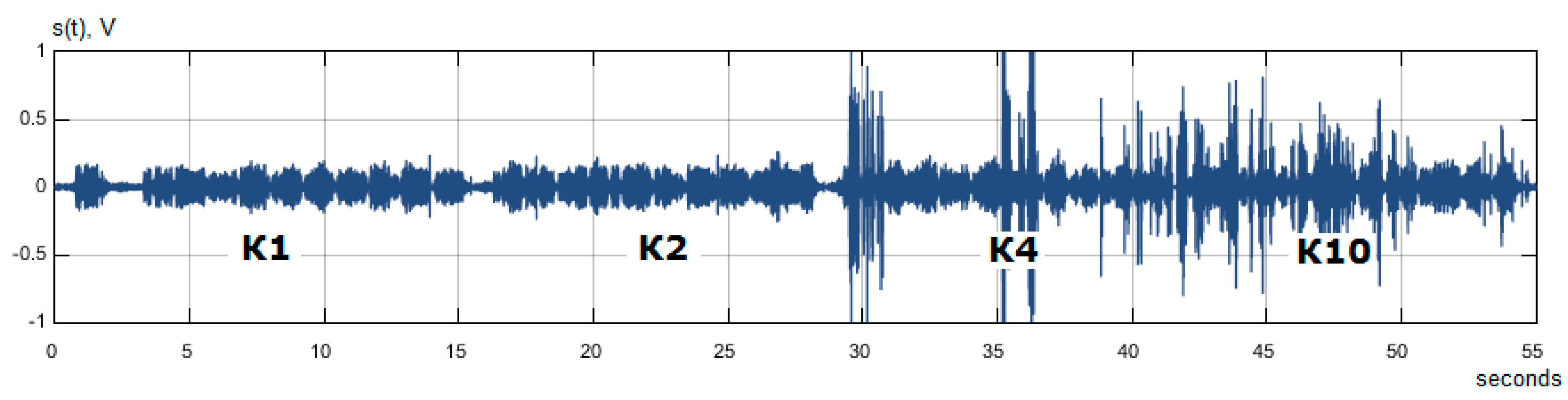
Also, by emitting test M-sequence preamble with a length of 63 elements and convoluting by the matched filter on the receiver side, some estimations of underwater acoustic channel impulse responses were obtained. The format of M-sequences emitting was determined as phase-manipulated signal. During the sea trials formed wav-files with FM-OFDM-QPSK signals were sequentially emitted within 53 s from the transmitter in following order: starting preamble → 10 symbols in the K1 mode → 10 symbols in the K2 mode→ 10 symbols in the K4 mode→ 10 symbols in the K10 mode.
Time diagram of the recorded signals are shown in Figure 6. In the received signals, the presence of strong impulse noises, resulted by external factors and noises of vessel equipment, can be noted. Average recorded values of the SNR were 20 dB and higher.

Figure 6.
Time diagrams of the recorded signals on the 25 km distance.
For the recorded data amplitude clipping with saturation parameter γ = 0.5 was implemented, which helped to substantially decrease the resulting BER and the influence of strong impulse noises on the records, while decoding FM-OFDM-QPSK signals.
To estimate a channel dynamic all three fragments went through symbol-by-symbol estimation of amplitude-frequency response of the channel in the bandwidth of 300–500 Hz by point FFT comparison of transmitted and acquired signals. The dynamic of amplitude-frequency response of the channel for the first three 53 s fragments of data transmission is presented in Figure 7.
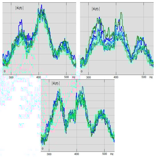
Figure 7.
Dynamic of amplitude-frequency response of underwater acoustic channel for all three iterations of FM-OFDM-QPSK symbols transmission.
Based on performed estimation of amplitude-frequency response of the channel, it can be stated that during time of three packets transmission the transfer that is characteristic of the underwater acoustic channel is changing substantially on such a big distances. For that case, the time-variant frequency channel transfer function can be described by expression:
where and —amplitude functions of two rays arriving to the receiver with time lag T. Values of functions for this case belongs to range .
According to the Figure 7, the interval of channel frequency coherence during the experiments was 70–80 Hz, which results beams path difference of .
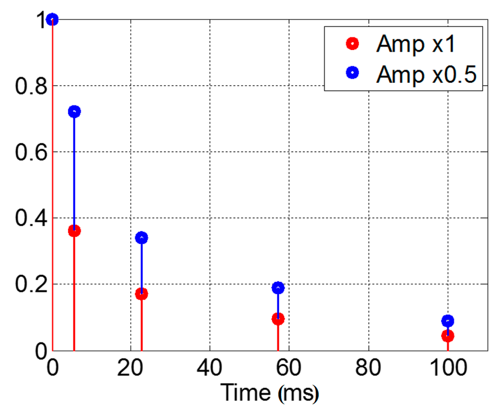
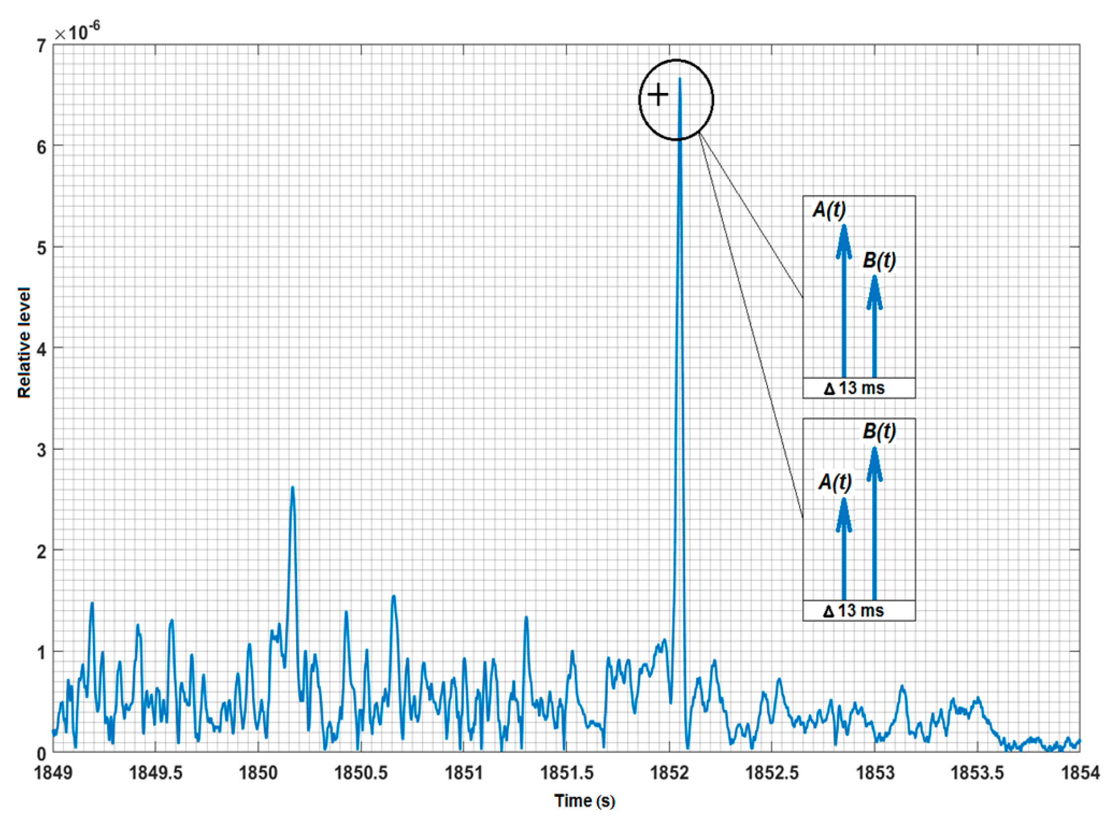
In Figure 8, the response of receiver matched filter on the M-sequence preamble is presented. The response represents an impulse response of underwater acoustic channel (with assumption that M-sequence autocorrelation function is ideal) in scale of several seconds. Specification of ray pattern in millisecond scale was acquired based on expression (8), and is also shown on Figure 8.
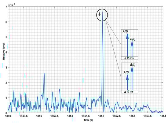
Figure 8.
Responses of the matched filter on the M-sequences with length of 63 symbols.
Further frame synchronization FM-OFDM-QPSK signals were performed using beam with the maximum amplitude. According to the test responses of underwater acoustic channel preliminary overlapping of weaker delayed copies of the FM-OFDM signals on the main symbol was detected. Such a situation created relatively “soft” conditions for OFDM symbols reception. In that case, conditions of numerical experiments (described in the Part 2) surpassed sea trials conditions in terms of level of difficulty of channel impulse response, which caused higher values of BER in numerical experiments. Results of decoding of FM-OFDM-QPSK signals that were received during in-situ experiments are presented in the Table 3.
Table 3.
Results of decoding of FM-OFDM-QPSK signals, recorded during sea trials on the distance of 25 km.
To estimate the correspondence between performance data acquired during additional numerical simulation and values that were obtained during following sea trials two channel responses were chosen because they were similar to the ones obtained during real underwater acoustic channel amplitude-frequency response estimation on the distances up to 25 km. Analytically, these responses each consisted of two beams with 13 ms difference in time of arrival can be presented as:
The system of FM-OFDM frame synchronization (SYNC) was tuned in two variants: for the work relying on the first beam and beam with the maximum magnitude. The BER results under signal convolution in the K1, K2, K3, and K10 mode with the responses and and SNR = 15 dB and different synchronization type is shown in the Table 4.
Table 4.
BER for different modes of FM-OFDM for channels with responses and under SNR of 15 dB and different synchronization types.
Simulation results with different synchronization types shows the necessity in precise frame synchronization of demodulated OFDM-QPSK symbols on beam with the maximum amplitude.
Obtained during sea trials results have good accordance with results of numerical modeling in the Table 3. However, numerical models have no consideration of strong impulse noises on the receiving signal, and as a result, BER obtained in sea trials are higher. To increase believability of the reception of transmitting data it is possible to use full complex transfer characteristic of the channel for correction of OFDM symbols group by first estimating symbol with periodical repetition of the channel estimation.
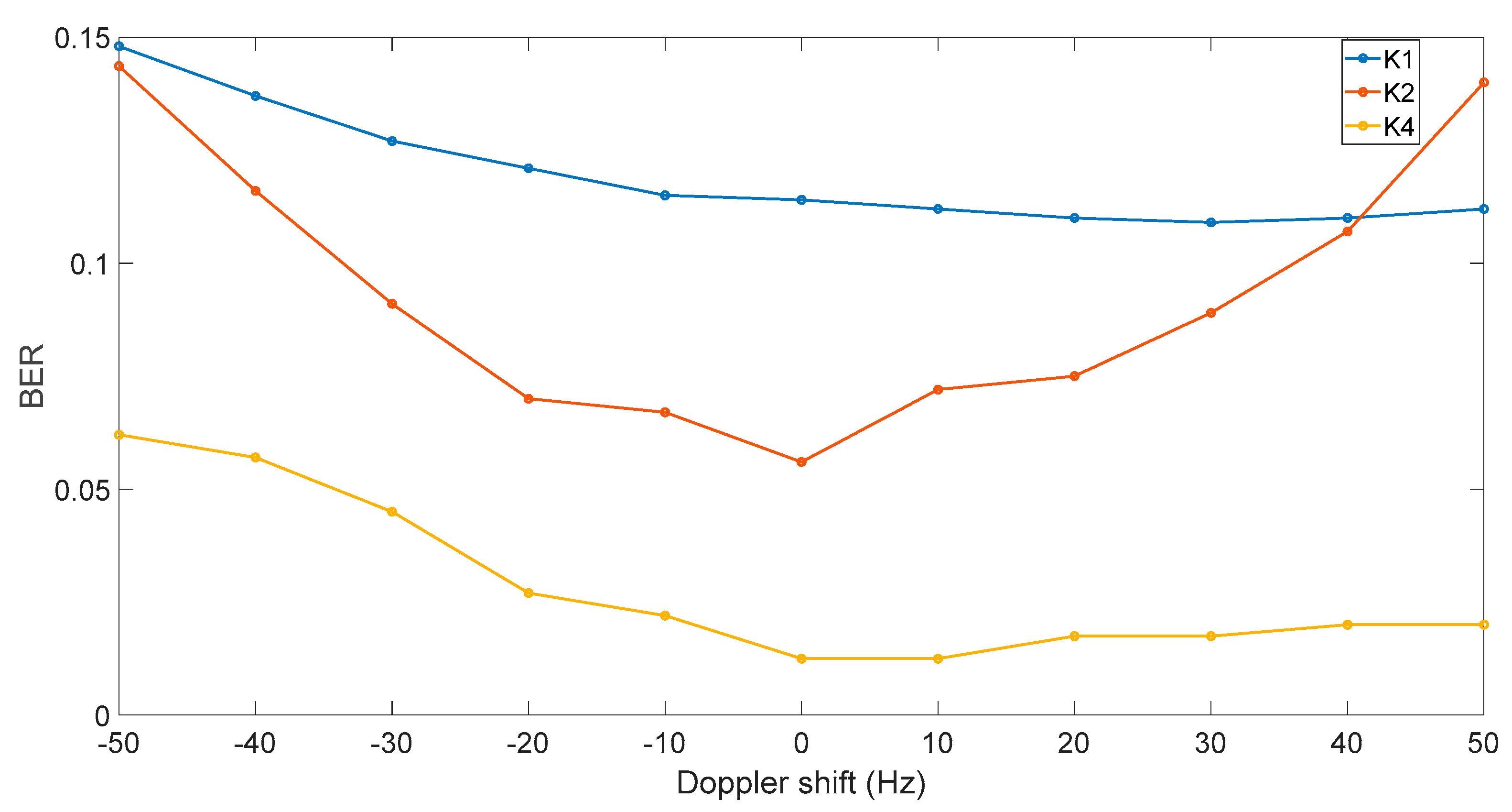
In conducted sea experiments, the Doppler shift was not observed in proper values due to low signal reflections from sea surface and the immobility of transmitter and receiver. So, the sea trials were supplemented by additional numerical modeling. Received signals were demodulated with artificially added strong frequency shifts for the estimation of FM-OFDM Doppler shift resilience. Additional estimations of BER for different modes were made during modeling.
As mentioned before, the frequency shift of FM-OFDM signal causes an appearance of steady component in the real part of OFDM signal on the FM demodulator output, which has minimal influence on further OFDM demodulation using FFT. Serious deviations of carrier frequency (up to 10%), as it shown on Figure 9, lead to small changes in BER values for received signals in modes K1, K2, K4. Mode K10 did not shown any additional errors.
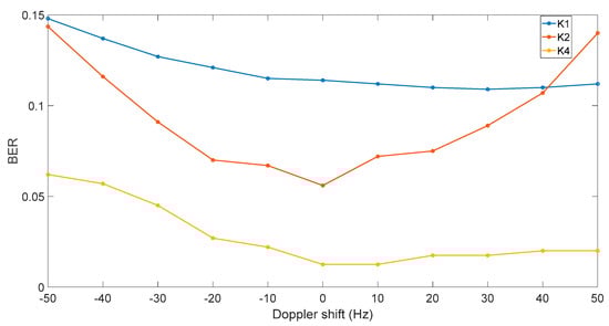
Figure 9.
BER of received signals of K1, K2, and K4 modes under artificial Doppler shift adding.
5. Conclusions
The usage of FM-OFDM modulation method in underwater acoustic communication channels can be justified by the available possibilities and advantages, for example: non-linear signal processing in transmitting and receiving paths with clipping of strong impulse noises; resilience to Doppler frequency shifts; keeping acceptable data throughput in spite of big time guard intervals, which is unobtainable for other modulation technique. Also, the proposed method is very flexible in managing the spectrum spreading coefficients. That allows for using both narrow-band and wide-band FM-OFDM that are capable of working under conditions of low SNR with acceptable noise-sustainability.
However, the method has several disadvantages, for example: decreased spectral efficiency when compared to regular OFDM by a factor of two; appearance of non-linear distortions in OFDM signal, when received signal contains strong reflected beams. These problems must be addressed with additional research and ways of signal correction, which are not covered by this paper.
In presented work, the methods of orthogonal frequency division multiplexing in combination with additional frequency modulation (FM-OFDM-QPSK) were presented. The results of marine experiments at the distance of 25 km using low frequency underwater acoustic equipment with central frequency of 400 Hz showed bit error rate of 0.13…0.001 in conditions of frequency-selective fading in underwater channel with data throughput of 167 bit/s. Similar performance was shown during numerical experiments under AWGN conditions without noise-sustainable coding for multipath responses similar to the ones that were obtained during sea trials. Sensitivity to precision of frame synchronization in FM-OFDM-QPSK method allows utilization only in channels, parameters of which are relatively stable during the time of packet transmission. In cases of active movement of receiver relative to transmitter, resulting non-stationarity of the channel substantially complicates frame synchronization of OFDM symbols.
Further research will be performed by the team in the field of multi-frequency methods utilization for long-haul underwater acoustic communications under conditions of non-stationary channels and for AUV communication in the aquatic areas with ice coverage.
Acknowledgments
This research was supported and funded by Russian Science Foundation, Project No. 16-19-00038, and by MTIT center (Ministry of Oceans and Fisheries, Korea) as a part of the project titled ‘Domestic products development of marine survey and ocean exploration equipments’.
Author Contributions
Aleksandr Rodionov, Lyubov Statsenko and Peter Unru designed and proposed the method; Yury Morgunov and Aleksandr Golov designed and performed the experiment; Eugene Voitenko and Alexey Kiryanov processed and analyzed the experiment results; all authors contributed to writing the manuscript.
Conflicts of Interest
The authors declare no conflict of interest.
References
- Dubrovin, F.; Scherbatyuk, A. About accuracy estimation of AUV single-beacon mobile navigation using ASV, equipped with DGPS. In Proceedings of the OCEANS 2016 MTS/IEEE Conference, Shanghai, China, 10–13 April 2016. [Google Scholar] [CrossRef]
- Sergeenko, N.; Scherbatyuk, A.; Dubrovin, F. Some algorithms of cooperative AUV navigation with mobile surface beacon. In Proceedings of the OCEANS 2013 MTS/IEEE Conference, San Diego, CA, USA, 23–27 September 2013. [Google Scholar] [CrossRef]
- Sharif, B.S.; Neasham, J.; Hinton, O.R.; Adams, A.E. A computationally efficient Doppler compensation system for underwater acoustic communications. IEEE J. Ocean. Eng. 2000, 25, 52–61. [Google Scholar] [CrossRef]
- Ma, L.; Qiao, G.; Liu, S. A combined doppler scale estimation scheme for underwater acoustic OFDM system. J. Comput. Acoust. 2015, 23, 1540004. [Google Scholar] [CrossRef]
- Ming, L.; Lin, Z.; Yide, Z. A novel Doppler frequency shift compensation algorithm for OFDM underwater acoustic communication system. In Proceedings of the 2013 25th Chinese Control and Decision Conference, Guiyang, China, 25–27 May 2013; pp. 1571–1575. [Google Scholar]
- Liu, L.; Zhang, Y.; Zhang, P.; Zhou, L.; Li, J.; Jin, J.; Zhang, J.; Lv, Z. PN sequence based Doppler and channel estimation for underwater acoustic OFDM communication. In Proceedings of the 2016 IEEE International Conference on Signal Processing, Communications and Computing (ICSPCC), Hong Kong, China, 5–8 August 2016; pp. 1–6. [Google Scholar]
- Chen, Y.; Zou, L.; Zhao, A.; Yin, J. Null subcarriers based Doppler scale estimation for multicarrier communication over underwater acoustic non-uniform Doppler shift channels. In Proceedings of the 2016 IEEE/OES China Ocean Acoustics (COA), Harbin, China, 9–11 January 2016; pp. 1–6. [Google Scholar]
- Kebkal, K.G.; Kebkal, V.K.; Kebkal, O.G.; Petroccia, R. Underwater acoustic modems (s2cr series) for synchronization of underwater acoustic network clocks during payload data exchange. IEEE J. Ocean. Eng. 2016, 41, 428–439. [Google Scholar] [CrossRef]
- Rodionov, A.Y.; Unru, P.P.; Statsenko, L.G. Orthogonal frequency-pulsed frequency-division multiplexing in underwater communications systems. Proc. Mtgs. Acoust. 2015, 24. [Google Scholar] [CrossRef]
- Ling, J.; He, H.; Li, J.; Roberts, W.; Stoica, P. Covert underwater acoustic communications. J. Acoust. Soc. Am. 2010, 128, 2898–2909. [Google Scholar] [CrossRef] [PubMed]
- Yan, H.; Wan, L.; Zhou, S.; Shi, Z.; Cui, J.; Huang, J.; Zhou, H. DSP based receiver implementation for OFDM acoustic modems. Phys. Commun. 2012, 5, 22–32. [Google Scholar] [CrossRef]
- Berger, C.R.; Zhou, S.; Preisig, J.C.; Willett, P. Sparse channel estimation for multicarrier underwater acoustic communication: From subspace methods to compressed sensing. IEEE Trans. Signal Process. 2010, 58, 1708–1721. [Google Scholar] [CrossRef]
- Rodionov, A.Y.; Unru, P.P.; Statsenko, L.G.; Kir’yanov, A.V.; Chusov, A.A.; Scherbatyuk, A.F. Development of the preamble-based FM-OFDM underwater acoustic communication system using high-performance computing. In Proceedings of the 2016 17th International Conference on Sciences and Techniques of Automatic Control and Computer Engineering (STA), Sousse, Tunisia, 19–21 December 2016. [Google Scholar] [CrossRef]
- Rodionov, A.Y.; Kulik, S.Y.; Unru, P.P. Some trial results of the hydro acoustical communication system operation for AUV and ASV group control and navigation. In Proceedings of the OCEANS 2016 MTS/IEEE Monterey, Monterey, CA, USA, 19–23 September 2016. [Google Scholar] [CrossRef]
- Bezotvetnykh, V.V.; Burenin, A.V.; Morgunov, Y.N.; Polovinka, Y.A. Experimental studies of pulsed signal propagation from the shelf to deep sea. Acoust. Phys. 2009, 55, 376–382. [Google Scholar] [CrossRef]
- Burenin, A.V.; Bezotvetknyh, V.V.; Voitenko, E.A.; Morgunov, Y.N. Experimental evaluation of the influence of the vertical sound velocity profile at the source site in shallow water on the formation of the pulse response characteristics in the deep sea. Acoust. Phys. 2010, 56, 47–48. [Google Scholar]
- Kumar, P.; Trivedi, V.K.; Kumar, P. Performance evaluation of DQPSK OFDM for underwater acoustic communications. In Proceedings of the 2015 IEEE Underwater Technology (UT), Chennai, India, 23–25 February 2015. [Google Scholar]
- Jin, L.; Li, Y.; Zhao, C.; Wei, Z.; Li, B.; Shi, J. Cascading polar coding and lt coding for radar and sonar networks. EURASIP J. Wirel. Commun. Netw. 2016, 2016, 254. [Google Scholar] [CrossRef]
- Akulichev, V.A.; Borodin, A.E.; Burenin, A.V.; Morgunov, Y.N.; Strobykin, D.S. Application of complex acoustic signals in the long-range navigation of underwater objects. Dokl. Earth Sci. 2007, 417, 1432–1435. [Google Scholar] [CrossRef]

© 2018 by the authors. Licensee MDPI, Basel, Switzerland. This article is an open access article distributed under the terms and conditions of the Creative Commons Attribution (CC BY) license (http://creativecommons.org/licenses/by/4.0/).