Abstract
Aerodynamics and motion performance of the floating vertical wind turbine (VAWT) were studied in this paper, where the wind turbine was H-type and the floating foundation was truss spar type. Based on the double-multiple-stream-tube theory, the formulae were deduced to calculate the aerodynamic loads acting on the wind turbine considering the motions of the floating foundation. The surge-heave-pitch nonlinear coupling equations of the H-type floating VAWT were established. Aerodynamics and motion performance of a 5 MW H-type floating VAWT was studied, and the effect of the floating foundation motions on the aerodynamic loads was analyzed. It is shown that the motions of the floating foundation on the aerodynamics cannot be ignored. The motion of the H-type floating VAWT was also compared with that of the Φ-type floating VAWT: they have the same floating foundation, rated output power, mooring system and total displacement. The results show that the H-type floating VAWT has better motion performance, and the mean values of surge, heave and pitch of the H-type floating VAWT are much smaller comparing with the Φ-type floating VAWT.
1. Introduction
With the increase of unit capacity, size of the offshore wind turbine is getting bigger and bigger. The instability of floating horizontal axis wind turbine (HAWT) may become obvious as the huge drive system is placed on the top of the high tower [1]. The drive system of Vertical Axis Wind Turbine (VAWT) is installed on the bottom, which has little effect on the dynamic behavior of the tower. This makes floating VAWT more advantageous in the development of large-scale offshore wind power [2].
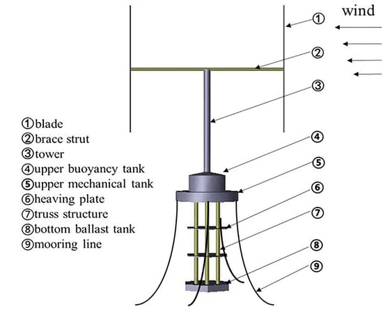
Darrieus wind turbine is the earliest lift type VAWT, and it has the higher power coefficient comparing with other VAWT [1]. According to the form of the blade, the Darrieus wind turbine includes curved blade and straight blade, withib which the Φ-type and the H-type are the most common. With the development of the offshore wind farm, the feasibility of the Darrieus wind turbine is assessed to be used in deep water and supported by the floating foundation.
The research on the floating VAWT has been carried out, including the aerodynamic load calculations of the floating VAWT, the motion comparison of the VAWT supported by different floating foundations, the influences between aerodynamic and hydrodynamic loads, and so on. Some methods and codes were developed to calculate the floating VAWT, including the FloVAWT code [3], the enhanced Hawc2 code [4], Simo-Riflex-DMS (AC) code [5,6], and a rigid-flexible coupling code [7]. The motion performances of the floating VAWT were investigated by these codes. Vita studied the feasibility of a 5 MW Φ-type wind turbine supported by a rotating spar type foundation by using the enhanced Hawc2 code [4]. Borg and Collu calculated the responses of vertical wind turbines supported by different floating foundations by using the FloVAWT code [8]. Cheng et al. implemented the AC method in the Simo-Reflex to conduct the fully coupled aero-hydro-servo-elastic simulation of the floating VAWT [6,9]. Cahay et al. put forward the concept of a three-blade H-type wind turbine installed on a semi-submersible floating foundation [10].
In the above research, the form of the floating foundations mainly includes Spar type, Semi-submersible type, and TLP type. Liu et al. studied the motion performance of a 5 MW VAWT supported by the truss Spar platform [11], which had shorter length than the existent spar type foundation [12,13,14] and can be used in the moderate water depth with good motion performance, and had lighter weight than the existing semi-submersible type foundation [15]. The above codes cannot be used to calculate the truss Spar type VAWT, as the nonlinear coupling between the heave and pitch of truss Spar foundation is important, similar to the deep see Spar platform [16,17], and this is not considered in the above methods.
Compared with Φ-type, H-type is easier to manufacture and has higher power output [18]. In this paper, we studied the motion performances of the H-type VAWT supported by a truss Spar type floating foundation. The aerodynamic loads were calculated considering the dynamic stall and motions of the floating foundation. The surge–heave–pitch coupling nonlinear motion equations of the floating VAWT were established, and the motions of the floating VAWT were assessed.
2. The Aerodynamic Loads of H-Type Floating VAWT
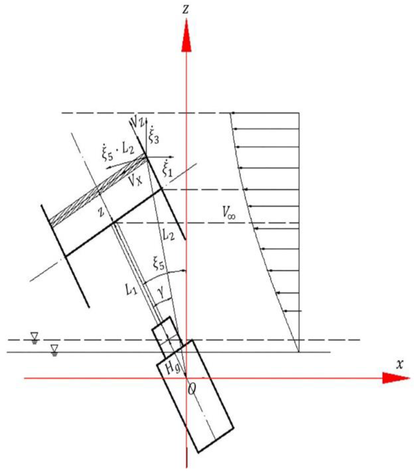
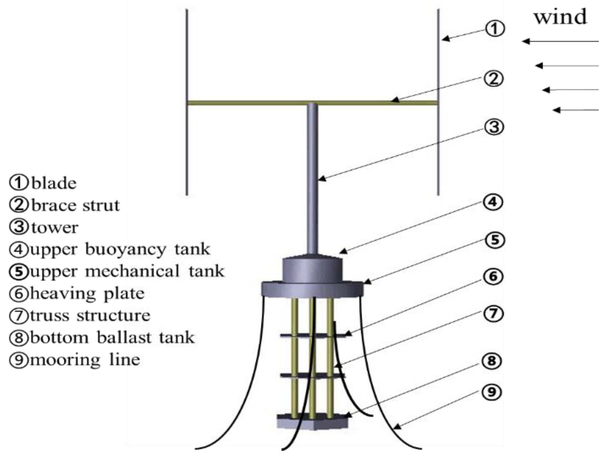
Based on the double multiple stream tube (DMST) theory, the aerodynamic loads acting on the blades were calculated considering dynamic stall, tip losses, aspect ratio, tower shadow effect and the influence of the surge–heave–pitch motions of the floater. The whole floating VAWT was dealt with as a rigid body.
The stream tubes were divided into upwind and downwind sectors, respectively. Coordinate system is shown in Figure 1, where the coordinate origin is in the center of gravity of the floating VAWT, and , , and are the displacements of surge, heave and pitch of the floating VAWT, respectively. The positive directions of the surge and heave motions are along the positive directions of the axis and 
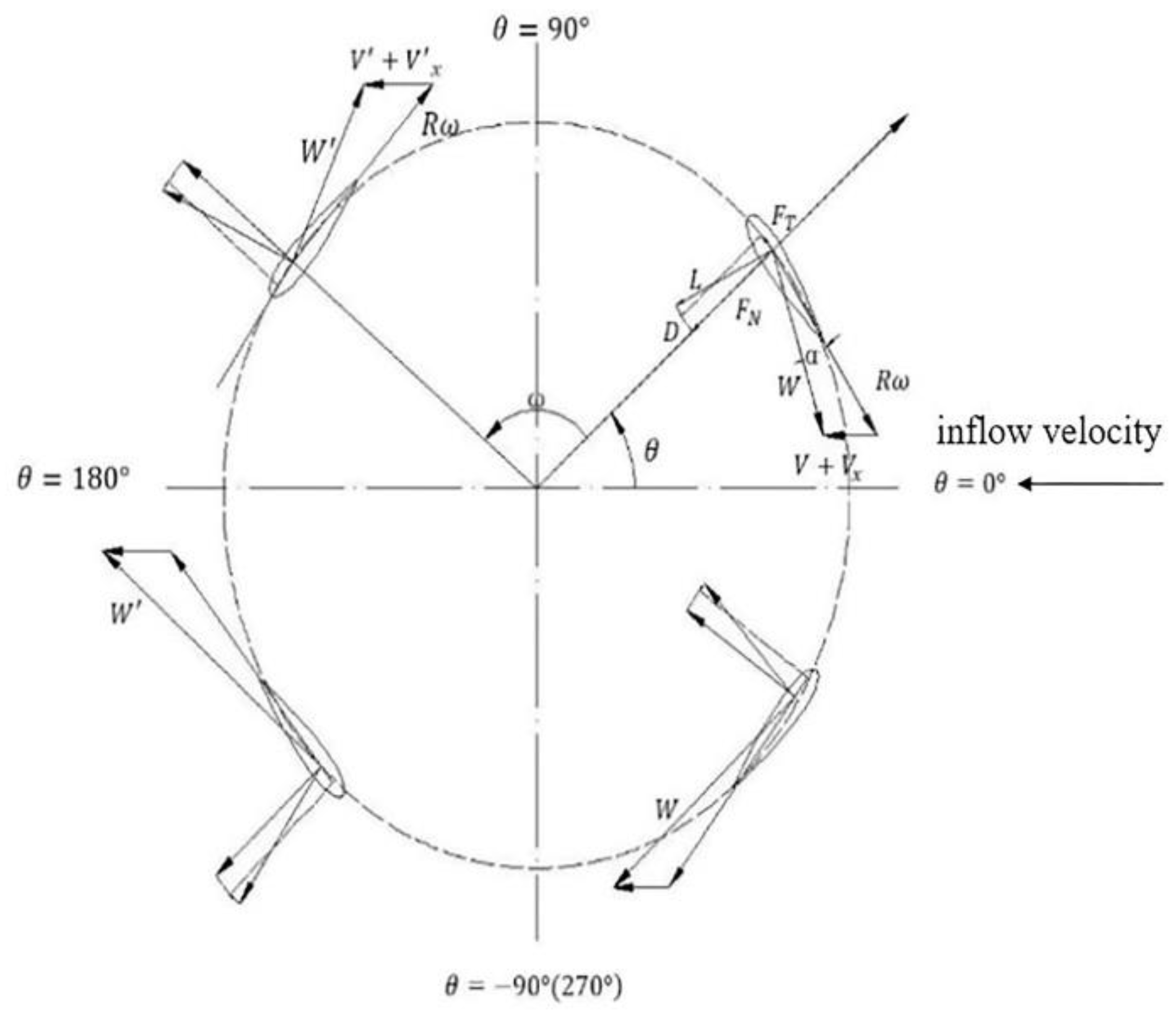
axis, respectively; the positive direction of the pitch motion is clockwise. The vector relations of the wind turbine are shown in Figure 2.
Figure 1.
Coordinate system.
Figure 2.
Equatorial velocity vector.
The steady wind was considered here, it was a function of the height above the water level, and for a local height , the wind speed can be written as follow,
where is the average wind velocity at a reference height , the vertical distance from the center of the blades to the water level is taken as the reference height in this paper, and with power [19].
Assuming the velocity parallel to the direction of the steam tube affects the induced velocities and the velocity perpendicular to the direction of the steam tube only affects the local relative velocities, the coordinate and the velocity of each stream tube were deduced considering the motions of the floating foundation in the following parts.
Induced velocities at the upwind and downwind sectors and , and the induced equilibrium velocity are given by [20],
where is the interference factor, and is the second interference factor.
For the upwind sector, the distance from local blades to the gravity center of floating wind turbine system is expressed as,
where is the radius of rotor, is the azimuth of rotor, is the distance from each stream tube to equator (below equator is negative direction), is the distance from equator to still water level, and is the distance from still water level to the gravity center of floating wind system when the system is in a state of stillness. The angle between the local position of the blade and the tower is written as
Then, the local wind velocity of the blade is given by,
where is the half-height of rotor. The velocities of local blades can be derived from the surge, heave and pitch velocities of floater by using transformation matrix. Then, the resultant velocities, which are caused by the motion of the floating foundation, parallel to the direction of the steam tube for the local position can be written as,
Using a similar deducing progress, we get the resultant velocities parallel to and vertical to the direction of the steam tube for the downwind sector, as follows,
For the rotor of upwind sector, namely, the range of azimuth is , and the local relative velocity of the rotor can be written as,
where is the rotation velocity of the blade.
The local attack of angle is derived as,
The azimuthal angle of upwind sector of the rotor is divided into several angular tubes, and the angle of each tube is . Assuming the induced velocity for each angular tube is a constant, the interference factor of each angular tube is a constant, it can be presented as,
where , and can be given by following expressions,
where is the number of blade, is the chord length, and and are the normal force and tangential force coefficients, respectively, they can be given by,
where and are the lift coefficient and the drag coefficient, respectively. 2D static coefficient and can be obtained by interpolation of the experimental data [21] considering the local Reynolds number and the local attack angle , and 3D static coefficient and can be derived by taking into account the influence of tip losses and finite aspect ratio [22]. Finally, the coefficients can be corrected by the Gormont–Berg method about the dynamic stall [23].
The local Reynolds number is presented as,
where is the coefficient of kinematic viscosity.
For the given the geometric lines of rotor, rotational speed and wind speed of each stream tube, the final induced factor can be derived by iteration of Equations (2)–(18). Furthermore, the normal force and tangential force coefficients can be obtained.
The normal force and tangential force of the blade at different are further calculated by the following formulae,
where is local height of the stream tube to equator plane of the rotor.
The thrust force and side force of the blade are calculated as following,
The power coefficient is presented as following,
Similarly, the normal force and the tangential force can be calculated for the downwind sector, and obtain the power coefficient . The power coefficient for one cycle can be written as,
In this paper, the steady wind speed was used to calculate the aerodynamics loads. The lift and thrust forces acting on the heave and surge of the floating VAWT can be obtained by decomposing the normal and tangential forces. Calculating the moment of the thrust force about the center of gravity of the floating VAWT, the pitch moment of the aerodynamics acting of the pitch motions of the floating VAWT can be obtained.
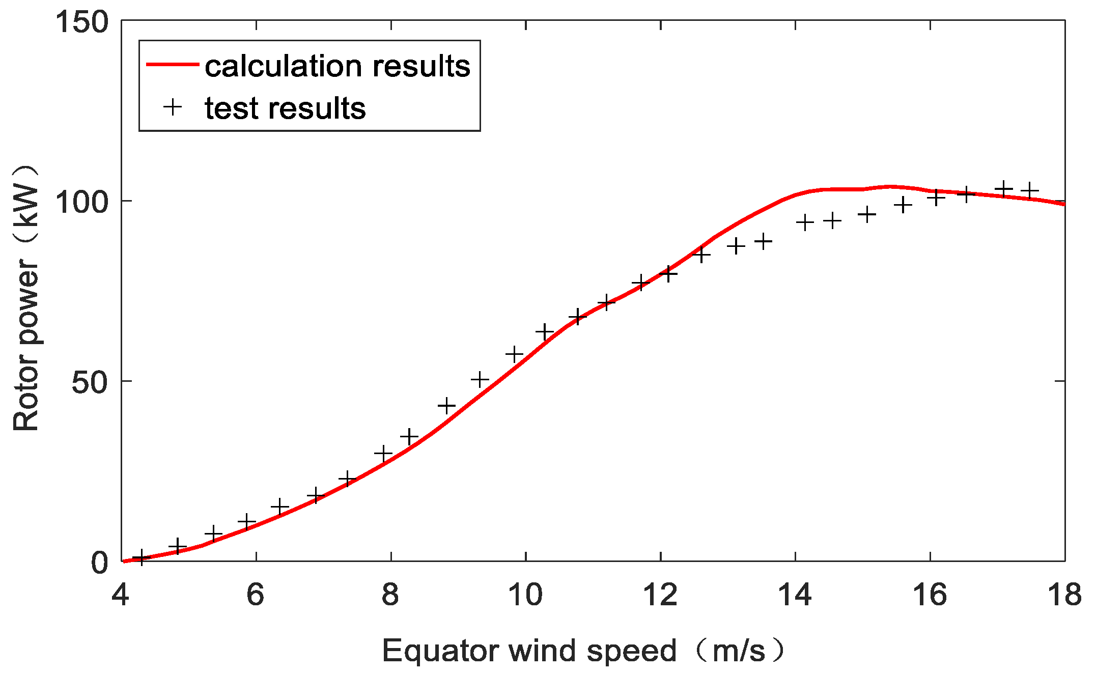
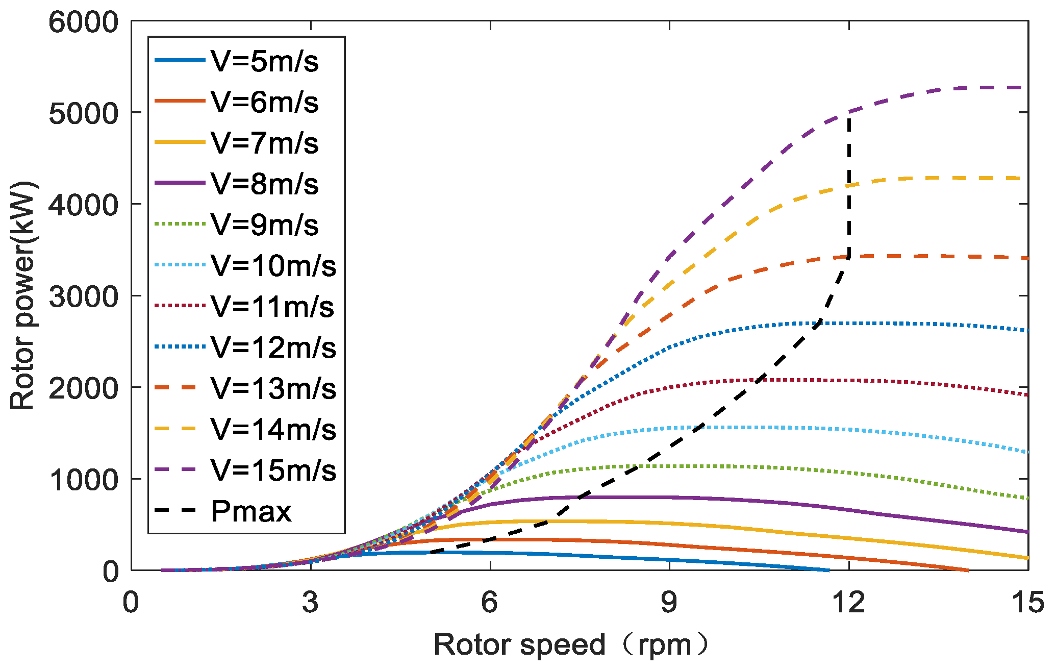
Taking a fixed H-type wind turbine VAWT260 [24] as an example, the rotor power was calculated (the coupling of aerodynamics and hydrodynamics was not considered in this part). The VAWT260 H-rotor has two blades with chord length of 1.02 cm and airfoil of NACA0018. The lift and drag coefficients used in this paper are from static test, and iteration residual standard is set to . The results of rotor power obtained by the numerical simulation were compared with those of model experiment [24], as shown in Figure 3.
Figure 3.
Validity checking of the aerodynamic loads.
It can be seen in Figure 3 that the rotor power obtained by the numerical simulation agrees well with the results of the experiment.
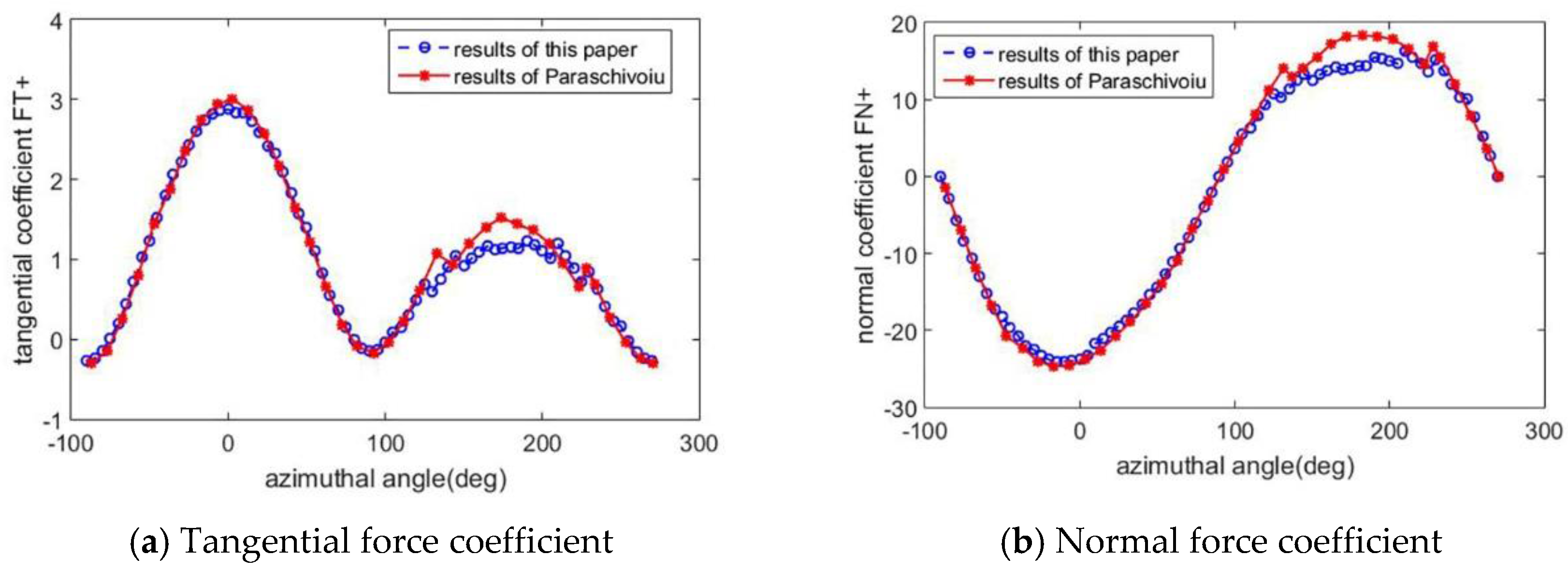
To verify the aerodynamic loads, comparisons of tangential and normal force coefficients with the calculation results of Paraschivoiu [25] are presented in Figure 4. A NACA0015 blade profile, a chord of 0.2 m and 6 m high H-type blade is used here. The rotational speed is 125 rpm, and the tip speed ratio is 5.2. The double multiple stream tube method with considering finite aspect ratio is used in [25].
Figure 4.
Validity checking of the aerodynamic loads.
Figure 4 shows that the aerodynamic load coefficients mainly agree well with the results of Paraschivoiu. The reason for the relatively obvious differences appearing downwind is that the tower effect is ignored in Paraschivoiu’s calculation. The thrust force and side force used in the dynamical equation in Section 3 can be checked by Equations (21) and (22).
3. The Dynamical Equations of the Floating VAWT
3.1.The Nonlinear Coupled Motion Equations
Liu et al. [16] established the nonlinear coupled motion equations of the Spar platform, and verified the equations by comparing with test modal. In this paper, the method is used to analyze the dynamic motion of the floating VAWT. Regarding the whole floating VAWT as a rigid body, considering the inertia force (moment), damping force (moment), restoring force (moment), mooring force, wind and wave loads, the surge–heave–pitch coupled equations of the floating VAWT can be presented as follows,
where is the mass matrix of the floating VAWT, is the mass matrix at infinite frequency, and is the retardation function accounting for the fluid memory effect , and represents the displacement, velocity and acceleration vectors of the floating VAWT at its center of gravity, respectively, and . is the restoring matrix, including the hydrostatic restoring, restoring of the mooring system, and the nonlinear hydrostatic restoring. is the exciting force vector, which includes the Froud–Krylov force , diffraction force , wind loads (including the aerodynamic loads and the wind loads calculated by the wind pressure theory), and hydrodynamic viscous force , where is the matrix of viscous damping coefficient,
For the Spar type floating foundation, the nonlinear coupling between the heave and pitch motions is significant. Referring to the nonlinear heave–pitch coupling motion equations of the deepsea truss Spar platform [16,17], the restoring matrix can be written as follows,
where represents restoring stiffness of the mooring system in surge and heave of the floating VAWT. is water plane area of the floating foundation, is the initial stability height of the floating VAWT, is the displacement, is the density of seawater, and is gravity acceleration. The hydrostatic restoring loads are calculated on the static equilibrium position of the floating VAWT.
3.2. Wind Pressure
The wind pressure and wind heeling moment acting on the tower and the blades (in the parked state) were calculated in accordance with the rules of the API [26], as follows,
where is the shape coefficient of the wind-bearing component; is the height coefficient of the wind-bearing component; is the frontal projected area of the wind-bearing component in the wind direction; is the distance from the wind force acting points to the rotation center of the floating VAWT; and is shown as Equation (1).
3.3. Hydrodynamic Loads
Hydrodynamic loads were calculated by using the potential theory and the Morison’s equation [27]. The potential theory was used to calculate the wave loads, added mass and radiation damping of the large scale structure (including the upper buoyancy tank, upper mechanical tank, heaving plates, and bottom ballast tank). The first-order wave loads and second-order mean drift forces were considered in this paper.
The Morison equation was used to calculate the inertial load and viscous drag load of the slender structure (truss structures, , where is the diameter of the structure and is the wave length). The transverse hydrodynamic force per unit length can be written as follows,
where and are the added mass and quadratic drag coefficients, respectively; is the transverse wave particle velocity; and is the local transverse body velocity.
The Wadam [28] was used to calculate the hydrodynamics in this paper. The wind turbine was in the parked state and the wind loads and mooring system were not considered in the hydrodynamic calculation, while the mass and shape of the blade were considered.
3.4. Damping and Mooring System
The heave plates were used to reduce the heave motions of the floating VAWT, and the viscous damping of floating foundation was important. In this paper, the viscous damping was obtained by the experiment of free decay model [29].
The mooring forces acting on the floating foundation in the directions of surge and heave were calculated by quasi-static catenary method, considering catenary mooring line and the fairlead set near the gravity center of the floating VAWT.
3.5. The Motions Calculation of the Floating VAWT
The motions calculation of the floating VAWT was carried out using the method of Runge–Kutta, and the computational procedures were as follows: give initial displacements and velocities of the floating VAWT to calculate the aerodynamic loads of the blades according to Equations (2)–(22); solve Equation (23) considering the wind and wave loads, and mooring loads; and calculate the new aerodynamic loads according to the new displacements and velocities of the floating VAWT. The coupling between aerodynamics and hydrodynamics was obtained by repeating the process above.
4. Results and Analysis
4.1. The Parameters of a 5 MW Floating VAWT
The H-type floating VAWT studied as an example is shown Figure 5. The upper wind turbine refers to the VAWT proposed by Collu et al. [15], and the floating foundation is Truss Spar type, which consists of buoyancy tank, the upper machinery tank, truss structure, heave plates and ballast tank. The specific parameters of the floating VAWT are shown in Table 1. The floating VAWT was located by four groups (one line for each group), the angle between each group of mooring lines was 90°. The lines were designed in the form of chain–cable–chain, and were connected with the floating foundation by the fairleads. The specific parameters of the mooring line are indicated in Table 2.
Figure 5.
The H-Type floating VAWT system. VAWT: Vertical Axis Wind Turbine.
Table 1.
Parameters of the floating VAWT. VAWT: Vertical Axis Wind Turbine.
Table 2.
Parameters of the mooring line. EA: XXX.
4.2. Control Strategy of Rotational Speed
The control strategy of rotor speed of the floating VAWT is as follows: for wind speeds less than 12 m/s, the rotational speed is designed to obtain the maximum power capture; the rotational speed is set to the rated rotational speed when wind speed is in the range of 12–15 m/s; and for wind speeds more than the rated wind speed, the rotational speed should be set to maintain the rated output power. Output power for different rotor speed and wind speed are shown in Figure 6, and rotor speed and output power for the different wind speed are shown in Figure 7.
Figure 6.
Power for different rotational speed and wind speed.
Figure 7.
Power and rotational speed for different wind speed.
4.3. Results and Analysis
4.3.1. Free Decay Motions of the Floating VAWT
The free decay motions were carried out in this section. The wind turbine was in the parked state and wind and wave loads were not considered. The natural periods of surge, heave and pitch motions of the system are obtained as shown in Table 3.
Table 3.
Natural periods of the floating VAWT.
4.3.2. Motions of the Floating VAWT Considering the Wind and Regular Wave Loads
Motions of the floating VAWT were calculated considering the wind loads and regular wave loads in this section. The parameters of wave and wind are shown in Table 4.
Table 4.
Regular wave and wind cases (LC3).
The time histories and the corresponding spectra (obtained by the Fast Fourier Transform) of the floating VAWT motions are shown in Figure 8, Figure 9 and Figure 10, and the mean displacements and the corresponding standard deviations (STD) are shown in Table 5.
Figure 8.
Surge responses of the floating VAWT (LC3): (a) time histories; and (b) response spectra.
Figure 9.
Heave responses of the floating VAWT (LC3): (a) time histories; and (b) response spectra.
Figure 10.
Pitch responses of the floating VAWT (LC3): (a) time histories; and (b) response spectra.
Table 5.
The standard deviations and mean values (LC3). STD: standard deviations.
Table 5 shows that, for the three cases, the max STDs of the surge, heave and pitch motions of the floating VAWT are 1.55 m and 0.60 m and 2.64 degrees, respectively; the mean values of heave are all small, and the max mean values of the surge and the pitch motions of the three cases are 2.95 m and 3.27 degrees, respectively. Therefore, the floating VAWT has good motion performance. Compared with LC3.2, the pitch STD of the floating VAWT in LC3.3 increases by approximately 77%, and the corresponding mean value increases by approximately 25%.
In Figure 8, Figure 9 and Figure 10, we can find that the motion frequencies of the floating VAWT are dominated by the wave frequencies for the three cases. For the pitch frequencies of the floating VAWT, there are components of the rotor rotational frequency (2P response). However, they are not significant compared with the wave–frequency responses.
4.3.3. The Aerodynamics of the Floating VAWT
To analyze the effect of floating foundation’s motion on the aerodynamics, two conditions are considered for LC3.2: (a) the foundation is floating, and the couple motions of floating foundation are considered in aerodynamics calculation; and (b) the wind turbine is considered to be set on a fixed foundation. The normal and tangential forces acting on the equator of one blade are calculated, and the results of time histories and spectra are shown in Figure 11 and Figure 12.
Figure 11.
Time histories of aerodynamic force on the blade: (a) Normal force; and (b) Tangential force.
Figure 12.
Spectra of blade aerodynamics: (a) Normal force spectra; and (b) Tangential force spectra.
Figure 11 and Figure 12 show that the normal force is much bigger than tangential force. Compared with the fixed foundation case, the amplitudes of normal force and tangential force of the floating foundation cases increase up to 9.4% and 16.3%, respectively. As shown in Figure 12, the main frequency of aerodynamic force is 2P frequency. In addition, for the floating foundation model, there are frequency components of wave frequency and the difference frequency between 2P and wave frequency.
4.3.4. Motions of the Floating VAWT Considering the Wind and Irregular Wave Loads
Motions of the floating VAWT were calculated considering the wind loads and irregular wave (JONSWAP sea spectrum) loads in this section. The calculation parameters are shown in Table 6.
Table 6.
Irregular wave and wind cases (LC4).
The time histories and spectra of pitch motions of LC4.2 and LC4.3 are presented in Figure 13. The max values, mean values and STDs of surge, heave and pitch responses of the floating VAWT are calculated, and the results are shown in Table 7.
Figure 13.
Pitch responses of the floating VAWT: (a) time histories; and (b) response spectra.
Table 7.
Response statistics of the floating VAWT (cases LC4).
Figure 12 shows that the pitch motions of the floating VAWT increase with the increase of wave height and wind speed, and they are still dominated by the wave–frequency motions. Comparing Figure 12b with Figure 9b, the 2P frequency caused by the aerodynamic loads is more significant in the case LC4. Because of the effect of heave plates, the heave responses are small and the max values of heave is 1.15 m for LC4. In Table 7, we can find that the STDs of surge and pitch motions of the floating VAWT are small, which shows the floating VAWT has good motion performance in the wave and wind conditions.
4.3.5. Comparison with Φ-Type Floating VAWT
Liu et al. studied a 5 MW Φ-Darrieus type wind turbine supported by the same truss Spar type floating foundation and with the same mooring system, and its parameters are presented in Reference [11]. Compared with the Φ-type wind turbine (blade height is 129.56 cm, mass of two blades is 308 tons), the blade height and blades mass of this paper decreased by 39% and 75%, respectively. The two floating VAWTs have the same total mass.
Motions of the two floating VAWTs were compared considering the wind loads and regular wave loads, and the calculation parameters are shown in Table 8. The mean value and STDs of the surge, heave, and pitch motions of the two floating VAWTs are presented in Figure 14, Figure 15 and Figure 16. The mean generator powers of the two floating VAWTs are shown in Figure 17.
Table 8.
Comparison cases (LC5).
Figure 14.
Surge comparison of two floating VAWTs (cases LC5).
Figure 15.
Heave comparison of two floating VAWTs (cases LC5).
Figure 16.
Pitch comparison of two floating VAWTs (cases LC5).
Figure 17.
Mean generator power of two floating VAWTs (cases LC5).
Figure 14, Figure 15 and Figure 16 show that compared with the Φ-type floating VAWT, the mean values of the H-type floating VAWT’s motions are much smaller. Taking the rated wind speed case (LC5.2) as an example, the mean values of surge, heave and pitch of H-type floating VAWT decrease 38%, 74.2% and 38.6%, respectively. Therefore, H-type VAWT withstand smaller wind loads compared with the Φ-type VAWT. The STDs of motions of the two floating VAWTs are almost same, as they are supported by the same floating foundation, and the STD of the floating VAWT motions mainly depends on the wave loads. Figure 17 shows that the motion of floating VAWTs has insignificant effect on the mean generator power for both type wind turbines. It is a satisfactory result for the prospective development of a floating VAWT.
5. Conclusions
The surge–heave–pitch coupling nonlinear motion equations of the H-type floating VAWT were established considering the coupling between aerodynamic and hydrodynamic loads, and the motions of a 5 MW H-type floating VAWT were studied. The motion of the H-type floating VAWT was also compared with that of the Φ-type floating VAWT; they have the same floating foundation and total displacement. The main conclusions are as follows:
- The natural periods of surge, heave, and pitch motions of the H-type floating VAWT are 51.2 s, 20.5 s, and 29.3 s, respectively. The small STDs of the LC3 and LC4 show the good motion performance of the H-type floating VAWT in the wave and wind conditions.
- The effects of wind and wave loads on the motions of the H-type floating VAWT are assessed. For LC3, the motion frequencies of the floating VAWT are dominated by the wave frequencies, and there are small components of 2P frequency for the pitch motions. The 2P frequency is more significant in irregular wave conditions (LC4).
- The effects of the floating foundation motions on the aerodynamics are also assessed. The results show that the normal force is much bigger than the tangential force. Compared with the fixed foundation case, the amplitudes of normal and tangential forces increase up to 9.4% and 16.3%, respectively, for the floating foundation case. Besides the 2P frequency, the frequencies of aerodynamics also include the wave frequency and the difference frequency between 2P and wave frequency for the floating foundation case. The effect of the floating foundation motion on the aerodynamics cannot be ignored.
- The H-type VAWT withstand smaller wind loads compared with the Φ-type VAWT, and mean values of the H-type floating VAWT’s motions are much smaller compared with the Φ-type floating VAWT. The STDs of motions of the two floating VAWTs are almost same, as they mainly depend on the wave loads.
Acknowledgment
The project was supported by the Natural Science Foundation of China (No. 51579176), the Natural Science Foundation of Tianjin (No. 16JCYBJC21200), and the Fund of the State Key Laboratory of Ocean Engineering, Shanghai Jiao Tong University (No. 1501).
Author Contributions
Ying Guo and Liqin Liu deduced the formulae and carried out numerical calculation; Xifeng Gao analyzed the data; and Wanhai Xu wrote the paper.
Conflicts of Interest
The authors declare no conflict of interest.
References
- Paraschivoiu, I. Wind Turbine Design with Emphasis on Darrieus Concept; Polytechnic International Press: Montreal, QC, Canada, 2002. [Google Scholar]
- Tjiu, W.; Marnoto, T.; Mat, S.; Ruslan, M.H.; Sopian, K. Darrieus vertical axis wind turbine for power generation II: Challenges in HAWT and the opportunity of multi-megawatt Darrieus VAWT development. Renew. Energy 2015, 75, 560–571. [Google Scholar] [CrossRef]
- Collu, M.; Borg, M.; Shires, A.; Brennan, F.P. Progress on the development of a coupled model of dynamics for floating offshore vertical axis wind turbines. In Proceedings of the ASME 32nd International Conference on Ocean, Offshore and Arctic Engineering, Nantes, France, 9–14 June 2013. OMAE2013-54337. [Google Scholar]
- Vita, L. Offshore Floating Vertical Axis Wind Turbines with Rotating Platform. Ph.D. Thesis, Danish Technical University, Copenhagen, Denmark, 2011. [Google Scholar]
- Wang, K.; Hansen, M.O.L.; Moan, T. Dynamic analysis of a floating vertical axis wind turbine under emergency shutdown using hydrodynamic brake. Energy Procedia 2014, 53, 53–69. [Google Scholar] [CrossRef]
- Cheng, Z.S.; Madsen, H.A.; Gao, Z.; Moan, T. A fully coupled method for numerical modeling and dynamic analysis of floating vertical axis wind turbines. Renew. Energy 2017, 107, 604–619. [Google Scholar] [CrossRef]
- Owens, B.C.; Hurtado, J.E.; Paquette, J.A. Aero-elastic modelling of large offshore vertical-axis wind turbines: development of the offshore wind energy simulation toolkit. In Proceedings of the 54th AIAA/ASME/ASCE/A-HS/ASC Structures, Structural Dynamics, and Materials Conference, Boston, MA, USA, 8–11 April 2013. [Google Scholar]
- Borg, M.; Collu, M. A comparison on the dynamics of a floating vertical axis wind turbine on three different floating support structures. Energy Procedia 2014, 53, 268–279. [Google Scholar] [CrossRef]
- Cheng, Z.S.; Madesn, H.A.; Gao, Z.; Moan, T. Numerical study on aerodynamic damping of floating vertical axis wind turbines. J. Phys. Conf. Ser. 2016, 753, 102001. [Google Scholar] [CrossRef]
- Cahay, M.; Luquiau, E.; Smadja, C.; Silvert, F. Use of a vertical wind turbine in an offshore floating wind farm. J. Pet. Technol. 2011, 63, 105–107. [Google Scholar]
- Liu, L.Q.; Guo, Y.; Jin, W.C.; Yuan, R. Motion performances of a 5 MW VAWT supported by spar floating foundation with heave plates. In Proceedings of the ASME 36th International Conference on Ocean, Offshore and Arctic Engineering, Trondheim, Norway, 25–30 June 2017. OMAE2017-62625. [Google Scholar]
- Paulsen, U.S.; Borg, M.; Madsen, H.A. Outcomes of the DeepWind conceptual design. Energy Procedia 2015, 80, 329–341. [Google Scholar] [CrossRef]
- Bedon, G.; Paulsen, U.S.; Madsen, H.A.; Belloni, F.; Castelli, M.; Benini, E. Aerodynamic Benchmarking of the Deepwind Design. Energy Procedia 2015, 75, 677–682. [Google Scholar] [CrossRef]
- Battisti, L.; Benini, E.; Brighenti, A.; Castelli, M.R.; Dell, A.S. Wind tunnel testing of the DeepWind demonstrator in design and tilted operating conditions. Energy Procedia 2016, 111, 484–497. [Google Scholar] [CrossRef]
- Collu, M.; Borg, M.; Manuel, L. On the relative importance of loads acting on a floating vertical axis wind turbine system when evaluating the global system response. In Proceedings of the ASME 35th International Conference on Ocean, Offshore and Arctic Engineering, Busan, Korea, 19–24 June 2016. OMAE2016-54628. [Google Scholar]
- Liu, L.Q.; Zhou, B.; Tang, Y.G. Study on the nonlinear dynamical behavior of deep sea spar platform by numerical simulation and model experiment. J. Vib. Control 2014, 20, 1528–1553. [Google Scholar] [CrossRef]
- Keyvan, S.; Atilla, I.; Martin, J.D. Response analysis of a truss spar in the frequency domain. J. Mar. Sci. Technol. 2004, 8, 126–137. [Google Scholar]
- Sandra, E. Evaluation of different turbine concepts for wind power. Renew. Sustain. Energy Rev. 2008, 12, 1419–1434. [Google Scholar]
- International Electrochemical Commission. Wind Turbines, Part 3: Design Requirements for Off-Shore Wind Turbines; IEC61400-3; International Electrochemical Commission: Geneva, Switzerland, 2009. [Google Scholar]
- Paraschivoiu, I. Aerodynamic loads and performance of the Darrieus rotor. J. Energy 1982, 6, 406–412. [Google Scholar] [CrossRef]
- Sheldahl, R.E.; Klimas, P.C. Aerodynamic Characteristics of Seven Symmetrical Airfoil Sections through 180-Degree Angle of Attack for Use in Aerodynamic Analysis of Vertical Axis Wind Turbines; Sandia National Laboratories: Albuquerque, NM, USA, 1981. [Google Scholar]
- Andrew, S. Development and Evaluation of an Aerodynamic Model for a Noval Vertical Axis Wind Turbine Concept. Energies 2013, 6, 2501–2520. [Google Scholar]
- Berg, D.E. An improved double-multiple stream tube model for the Darrieus type vertical-axis wind turbine. In Proceedings of the Sixth Biennial Wind Energy Conference and Workshop, Minneapolis, NM, USA, 1–3 June 1983; pp. 231–233. [Google Scholar]
- Morgan, C.A.; Gardner, P.; May, I.D.; Anderson, M.B. The Demonstration of a Stall Regulated 100 Kw Vertical Axis Wind Turbine. In Proceedings of the European Wind Energy Conference, Glasgow, UK, 10–13 July 1989. [Google Scholar]
- Paraschivoiu, I.; Desy, P.; Massont, C. Blade Tip, Finite Aspect Ratio, and Dynamic Stall Effects on the Darrieus Rotor. J. Propuls. Power 1988, 4, 73–80. [Google Scholar] [CrossRef]
- American Petroleum Institute. Design and Analysis of Station keeping Systems for Floating Structures; API RP-2SK; American Petroleum Institute: Washington, DC, USA, 2005. [Google Scholar]
- Faltinsen, O.M. Sea Loads on Ships and Offshore Structures; Cambridge University Press: Cambridge, UK, 1990. [Google Scholar]
- Pan, Z.Y.; Vada, T.; Finne, S. Benchmark study of numerical approaches for wave-current interaction problem of offshore floaters. In Proceedings of the ASME 35th International Conference on Ocean, Offshore and Arctic Engineering, Busan, Korea, 19–24 June 2016. OMAE2016-54411. [Google Scholar]
- Liu, L.Q.; Guo, Y.; Zhao, H.X.; Tang, Y.G. Dynamic modeling, simulation and model tests research on the floating VAWT. Chin. J. Theor. Appl. Mech. 2017, 49, 299–307. (In Chinese) [Google Scholar]
© 2018 by the authors. Licensee MDPI, Basel, Switzerland. This article is an open access article distributed under the terms and conditions of the Creative Commons Attribution (CC BY) license (http://creativecommons.org/licenses/by/4.0/).