1. Introduction
The 28th Meeting of the Parties to the Montreal Protocol adopted the Kigali Amendment on hydrofluorocarbons (HFC), now included in the Montreal Protocol [
1]. This historic agreement aims to reduce the use and production of HFC worldwide, with the goal being to reduce HFC emissions by over 80 billion tonnes of carbon dioxide equivalent (CO
2,e) by 2050. Kigali Amendment has fixed a phase-down schedule based on overall CO
2,e emissions, which is thus dependent on the GWP of each substance. This agreement follows the same action line as the F-Gas Regulation adopted in Europe [
2], which has limited the GWP value of the substances that could be used in different refrigeration applications according to different time lines. Referring to commercial refrigeration, the most important restrictions and limitations are: a GWP limit of 2500 for stationary equipment from 2020 on and the limit of GWP of 150 for multipack centralised refrigeration systems with rated capacity of more than 40 kW from 2022 on, except for the primary circuits of cascade systems, which GWP limit has been fixed in 1500. Another important aspect is the recharge limit with refrigerant of GWP higher than 2500, which has been fixed at 40 tonnes CO
2,e (10.15 kg of R-404A, 10.03 kg of R-507A). Those restrictions and agreements are facilitating the transition towards more environmentally friendly solutions based on natural working fluids [
3] and the development of more efficient refrigeration solutions [
4].
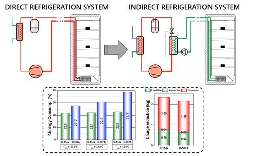
We focus on centralized commercial refrigeration systems with multiplexed direct expansion systems as they make the largest direct contribution to global warming because of their large refrigerant charge (300 to 3000 kg [
5]) and high annual leakage rate (between 15% and 25% [
6]). In addition, most of them still rely on high GWP refrigerants, such as R-404A (GWP = 3922), R-507A (GWP = 3985) and R-134a (GWP = 1430). According to Palm [
7], Melinder [
8] and Wang [
9], the use of indirect systems instead of direct expansion systems can reduce the total refrigerant charge by approximately 90%. The indirect configuration avoids refrigerant leakage through the distribution lines and services and reduces the overall annual leakage ratio since the refrigerant is contained inside the machinery room. However, indirect systems usually introduce an increment in the energy consumption of the system, caused by the extra temperature difference in the additional heat exchanger between the refrigerant and the secondary fluid and the energy consumption of the secondary pump. Nonetheless, this last effect could be minimized by a correct design of the indirect system, since by introducing a secondary loop the large pressure drops of the refrigerant through the distribution lines are avoided.
Several researchers analysed through simulation the performance of indirect systems regarding multiplexed direct expansion systems. Clodic et al. [
10] simulated, using field data, a French supermarket of 10,000 m
2 sales area with an R-404A primary system and propylene-glycol/water for MT and Tyfoxit for LT against a parallel R-404A multiplexed direct expansion system. They pointed out that the introduction of the secondary loops introduced 6 K at MT and 7 K at LT evaporating temperature drops, which resulted in a 33.7% increase in the system energy consumption regarding the direct expansion system. For this system, the refrigerant charge reduction was 56%. Horton [
11] contrasted an R22 multiplexed direct expansion system with an indirect ammonia–HFE 7100 indirect system, quantifying the reduction in energy consumption at 15%. Recently, Arias [
12], also simulating using field data, contrasted a multiplexed R-404A direct expansion system of a 2700 m
2 supermarket against a similar system using indirect loops, with propylene–glycol/water at 35% vol. for MT and with CO
2 for the LT. He estimated that the conversion to an indirect solution would avoid 90% of refrigerant charge but would incur a 3% increment in energy consumption. He also performed an estimation of the total emissions of the system to the atmosphere. For the case of Sweden, for an indirect emission factor of 0.04 kg·CO
2·kWh
−1 emissions would be reduced by 74.0%, but considering the average indirect emission factor for Europe (0.51 kg·CO
2·kWh
−1) the cut would be only 20.7% due to the increment of energy consumption of the indirect solution. Finally, Beshr et al. [
13] simulated an R-404A multiplexed direct expansion system for MT and LT, the same system with N40A as the main refrigerant and a split system with N40 in direct expansion for LT and L40 with a loop of propylene–glycol/water mixture for MT. The use of the indirect solution, under a scenario of annual leakage rate of 10%, resulted in an 89% reduction of direct emissions regarding the R-404A system and of 65% using N40. They stated that the indirect solution would offer a good balance between indirect emissions and energy consumption for cold climates, with an average annual leakage rate of 10%, and for all climates if the annual leakage rate were 2% or below [
13].
Regarding experimental comparisons, few research works have been found in the literature, mainly because of the cost and complexity of experimentation. You [
14] analysed an experimental R-404A direct expansion system against an R-404A with a subcooler indirect system using Temper 40
® as the secondary fluid. The system allowed for 88% charge reduction and 16.6% energy consumption reduction, but it must be highlighted that the primary system was different because the indirect solution incorporated a subcooling system. In addition, those systems operated with electric defrosting, measuring similar energy consumption in both solutions. Faramarzi and Walker [
15] presented the results of performance of a 3900 m
2 supermarket using an R-507A multiplexed direct expansion system against the same primary plant but with secondary fluid loops for MT and LT. In that plant, in which heat rejection was performed with an evaporative condenser, they measured a 4.9% energy consumption reduction with only 10% of refrigerant charge. They highlighted that the indirect solution could not be compatible with hot gas defrosting as electrical resistors were needed. Sánchez et al. [
16], under laboratory conditions, evaluated the energy impact of an R-134a/CO
2 direct cascade system against an R-134a-SF/CO
2 indirect cascade system. They measured an energy consumption increment between 7.6% and 14.0% when using a MT secondary loop with a propylene–glycol/water mixture and between −0.3% and 11.1% when using Temper −20
®. The other experimental works devoted to commercial indirect systems only focused on the performance of the system and not on the energy impact against a multiplexed solution [
17,
18,
19,
20,
21].
As can be observed from the literature review, indirect system solutions always offer large reductions in refrigerant charge and thus direct emissions; however, depending on the system, the energy impact can be positive or negative. A possible way to adapt multiplexed direct expansion systems to the F-Gas Regulation is to reconvert those systems into indirect solutions; however, it is not clear what the real impact would be. Accordingly, this work aims to provide accurate information about the conversion process from a direct to an indirect system using the most used refrigerants in existing plants and to establish a reference to evaluate different options to adapt commercial systems to the new regulations. Here, the experimental results of conversion of an R-134a and R-507A direct expansion system to an R-134a-SF and R-507A-SF refrigeration system for MT application are presented. Results concerning R-507A are expected to be representative of R-404A as well, since both mixtures present similar properties [
22]. The experimentation, performed under laboratory conditions, covered three heat rejection levels covering the most common heat rejection range of these systems.
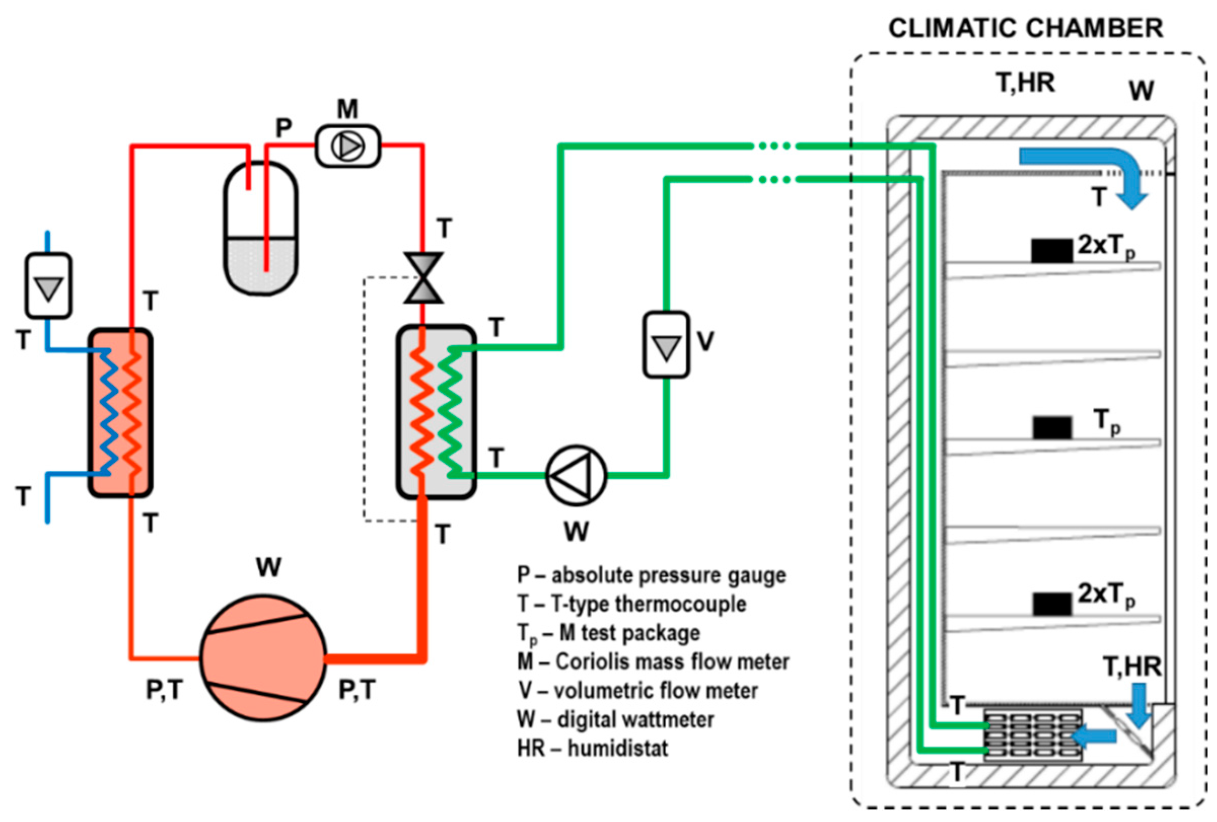
The paper is organised as follows: first, the experimental and measurement system is described, as well as the test methodology. Second, the main operating parameters of the system (temperatures, pressures, operating time and energy consumption) during the tests are analysed. Finally, the refrigerant charge reduction achieved with the conversion is presented.
3. Energy Consumption Tests
To evaluate the behaviour of the plant with the different refrigeration systems, 24-h energy tests were performed. The references for the tests were the average temperature of the M-test packages inside the cabinet, which was set to 2 °C, and the water inlet temperature to the condenser to perform heat rejection, which was set to 23.3, 32.8 and 43.6 °C with a constant volumetric flow rate of 1 m3·h−1, covering a wide range of operating conditions.
Table 3 summarizes the test conditions and the main reference parameters during the 24-h tests. Deviations during the test represent the standard deviations of the parameters.
3.1. Temperature Indicators
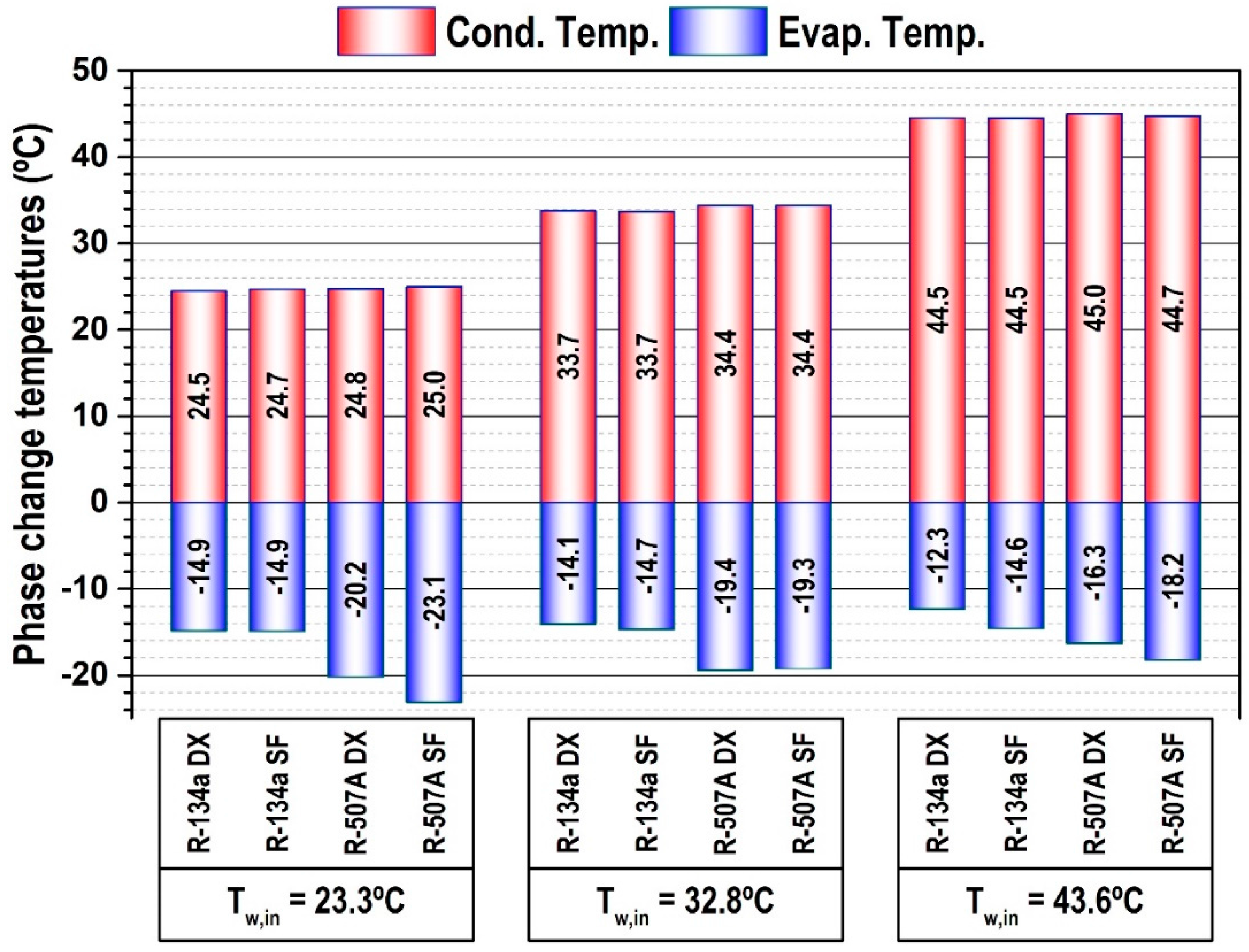
Figure 5 shows the average values of condensing and evaporating temperatures during 24-h test for both system layouts operating with R-134a and R-507A (the figure inside the bars gives the exact value). Condensing temperature is calculated using compressor’s pressure discharge measurement and a vapour title of 50%, according to Equation (1) [
24], only when the compressor was in operation. The evaporating level is averaged during the 24 h using the pressure at the exit of the evaporator of the cabinet in the case of the direct expansion configuration and using compressor suction pressure measurement for the indirect layout. Evaporation temperature is computed with Equation (2) using the indicated pressure measurements and the mean enthalpy in the evaporator [
24]. The thermophysical properties of the refrigerants are evaluated using Refprop 9.1 [
25].
Regarding the condensing level, no significant differences were observed among the system layouts and both refrigerants, being the maximum difference below 0.5 K. Regarding the evaporating temperature during the tests, some differences were observed. When going from a direct system to an indirect using R-134a as refrigerant, there is a reduction in the evaporating level, only from water inlet temperatures from 32.8 °C on. For 32.8 °C, the measured reduction was by 0.6 K, and for 43.6 °C by 2.3 K. However, the impact of the conversion is stronger when operating with R-507A. The reduction of the evaporating level when going to an indirect system was of 2.9 K at 23.3 °C, similar at 32.8 °C and of 1.9 K at 43.6 °C. Additionally, it must be mentioned that this reduction in the evaporating level is weakened by the behaviour improvement of the expansion valve when it operates with the indirect layout (brazed plate evaporator) instead of the direct arrangement (evaporator of the cabinet), reaching average superheat values in the evaporator during the 24 h lower (
Table 3).
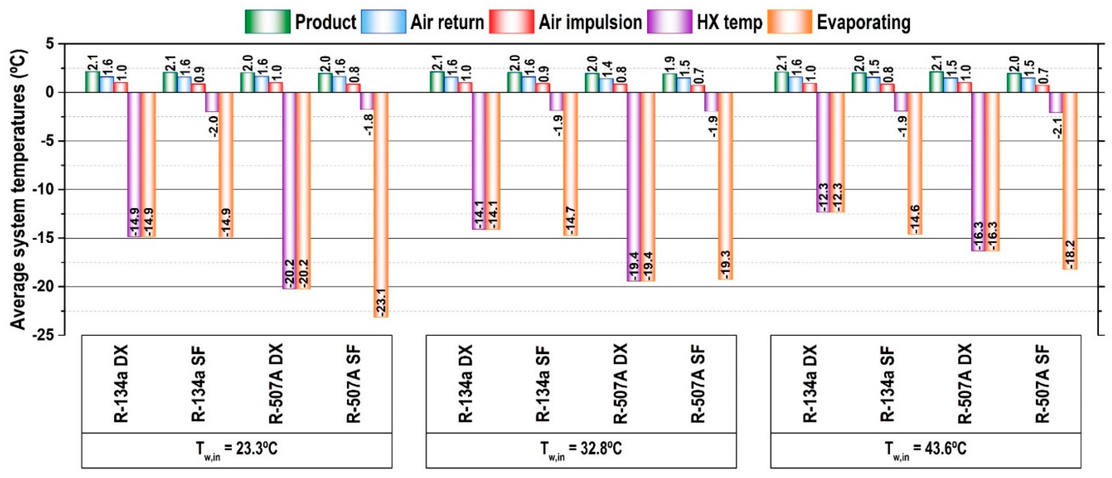
Referring to the working temperatures in the cabinet,
Figure 6 presents average values during 24 h of average product temperature (five samples), air return temperature to the heat exchanger of the cabinet, air impulsion at the air distribution port of the cabinet, the average temperature in the cabinet’s heat exchanger and the evaporating level. As can be observed, the operation, using a direct or indirect system, with both refrigerants has no influence on the air and product temperatures in the cabinet, since the product, air return and air impulsion temperatures are equivalent. The difference between the system layouts is observed in the working temperatures of the heat exchanger and the evaporating level. When using a direct expansion system, the cabinet’s heat exchanger temperature corresponds to the evaporating temperature (equal in the graph); however, when using an indirect system, the average working temperature of the heat exchanger of the cabinet (SF heat exchanger) largely differs from the evaporating level. For both refrigerants, the average temperature of the secondary fluid in the cabinet heat exchanger is −2.0 ± 0.3 °C. The differences between average temperature in the SF heat exchanger and the evaporating temperature are of 12.9 K, 12.8 K and 12.7 K when using R-134a, and of 21.3 K, 17.4 and 16.1 K when using R-507A.
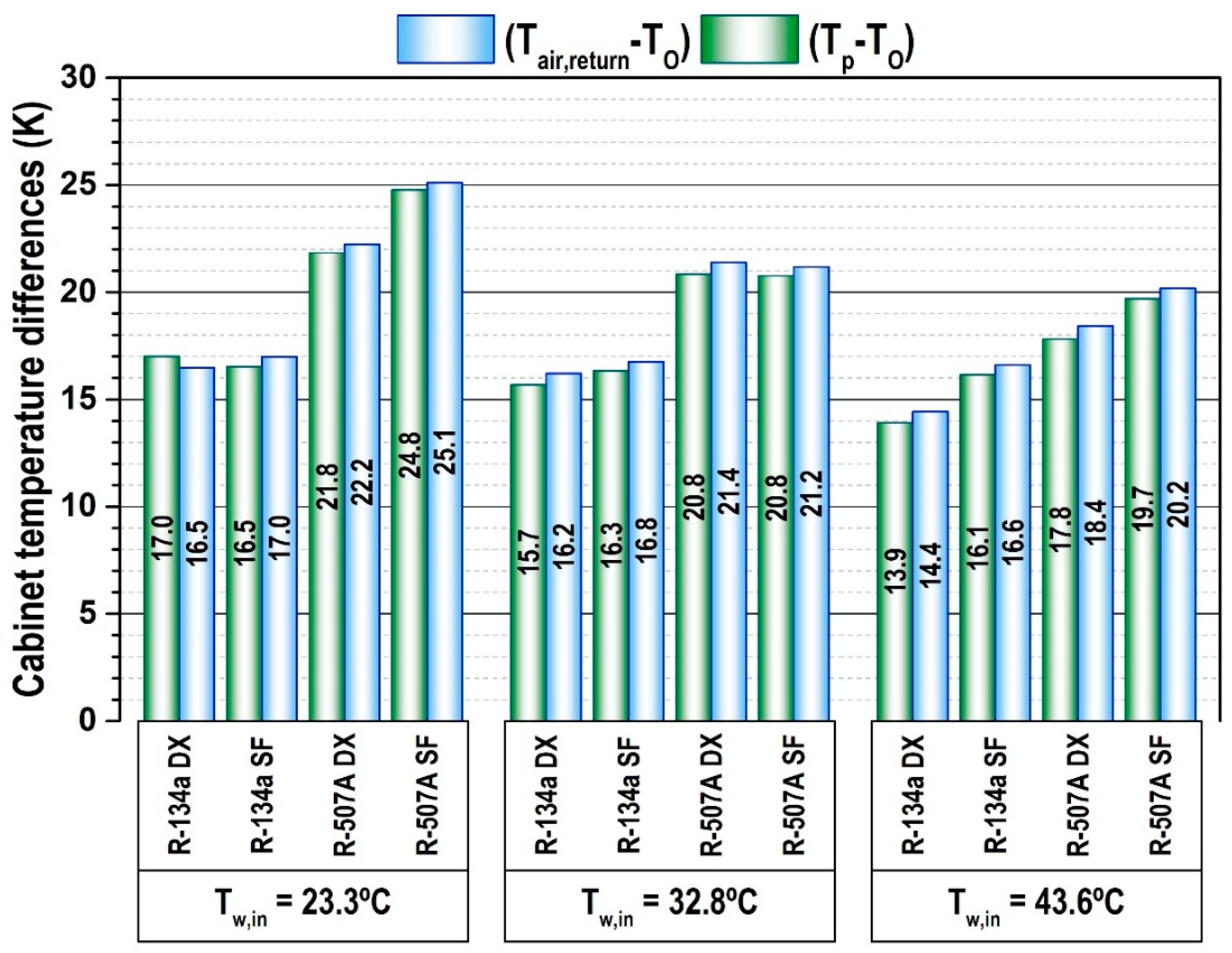
The impact of the indirect system on the working temperatures is summarized in
Figure 7, which shows the average temperature difference between the air at the return port to the cabinet heat exchanger and the evaporating temperature (Equation (3)) and between the product and the evaporating temperature (Equation (4)):
The use of an indirect layout instead of a direct expansion system provokes an increment of these temperature differences. Taking as reference the maximum temperature difference driving the heat transfer processes (product minus return air temperatures), the increments are of 0.5 K at 23.3 °C, 0.6 K at 32.8 °C and 2.2 K at 43.6 °C for R-134a, and of 2.9 K at 23.3 °C, −0.2 K at 32.8 °C and 1.8 K at 43.6 °C for R-507A. Obviously, the increment of the temperature difference driving heat transfer processes when going to an indirect layout will influence the energy consumption of the system, which is detailed in the next subsection.
3.2. Energy Indicators
Energy consumption is the relation between the operating time and the average power consumption of the elements.
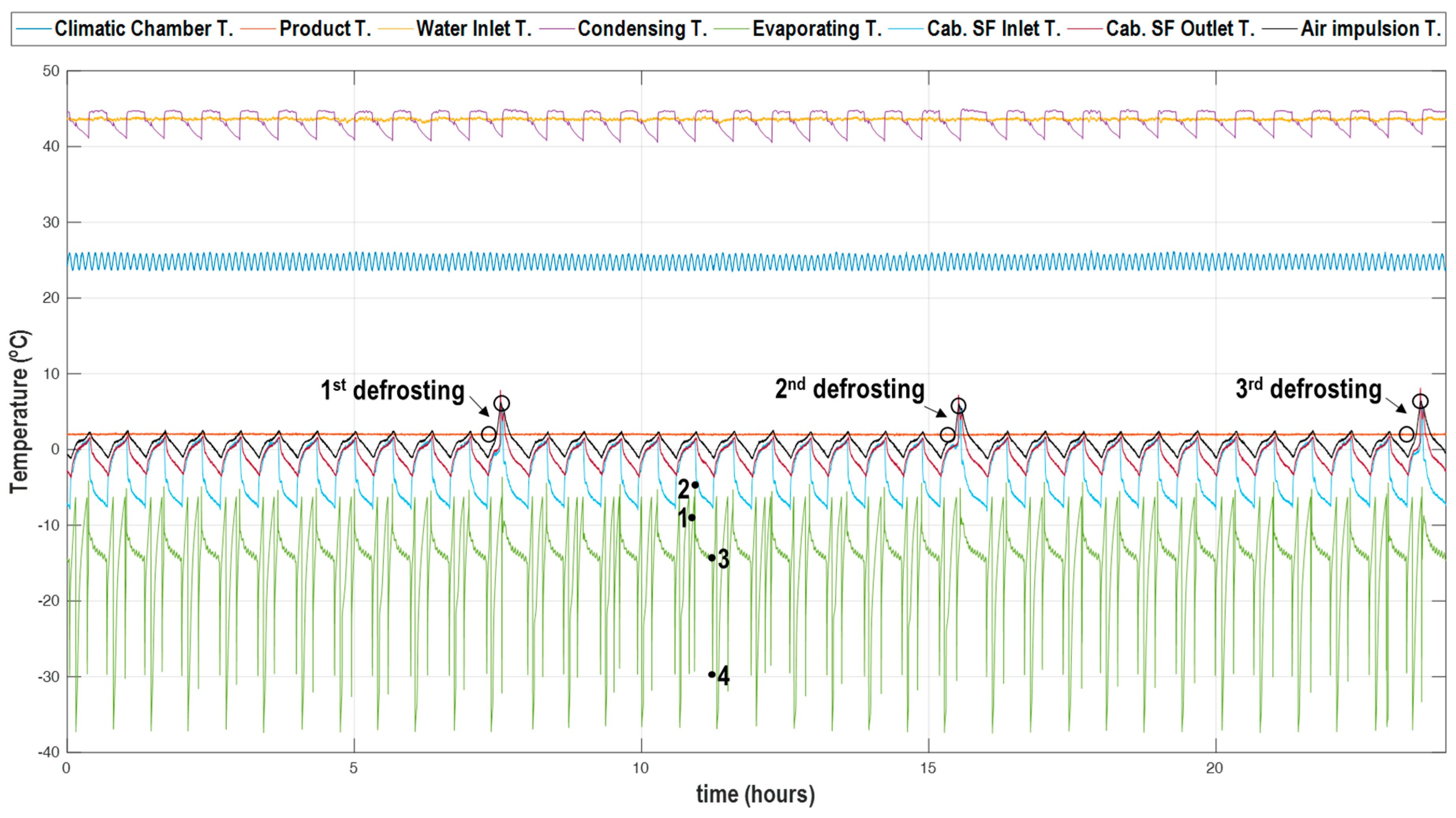
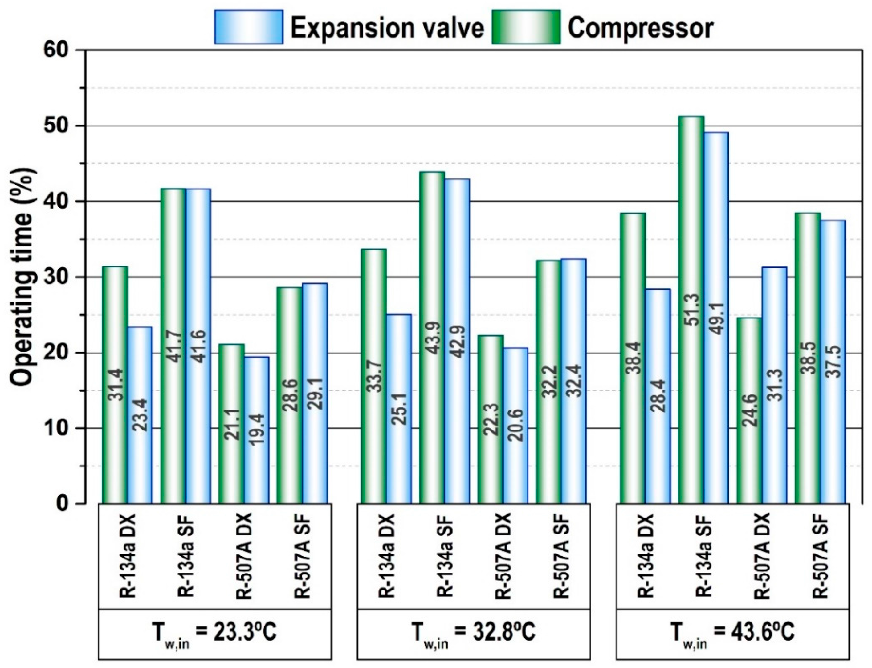
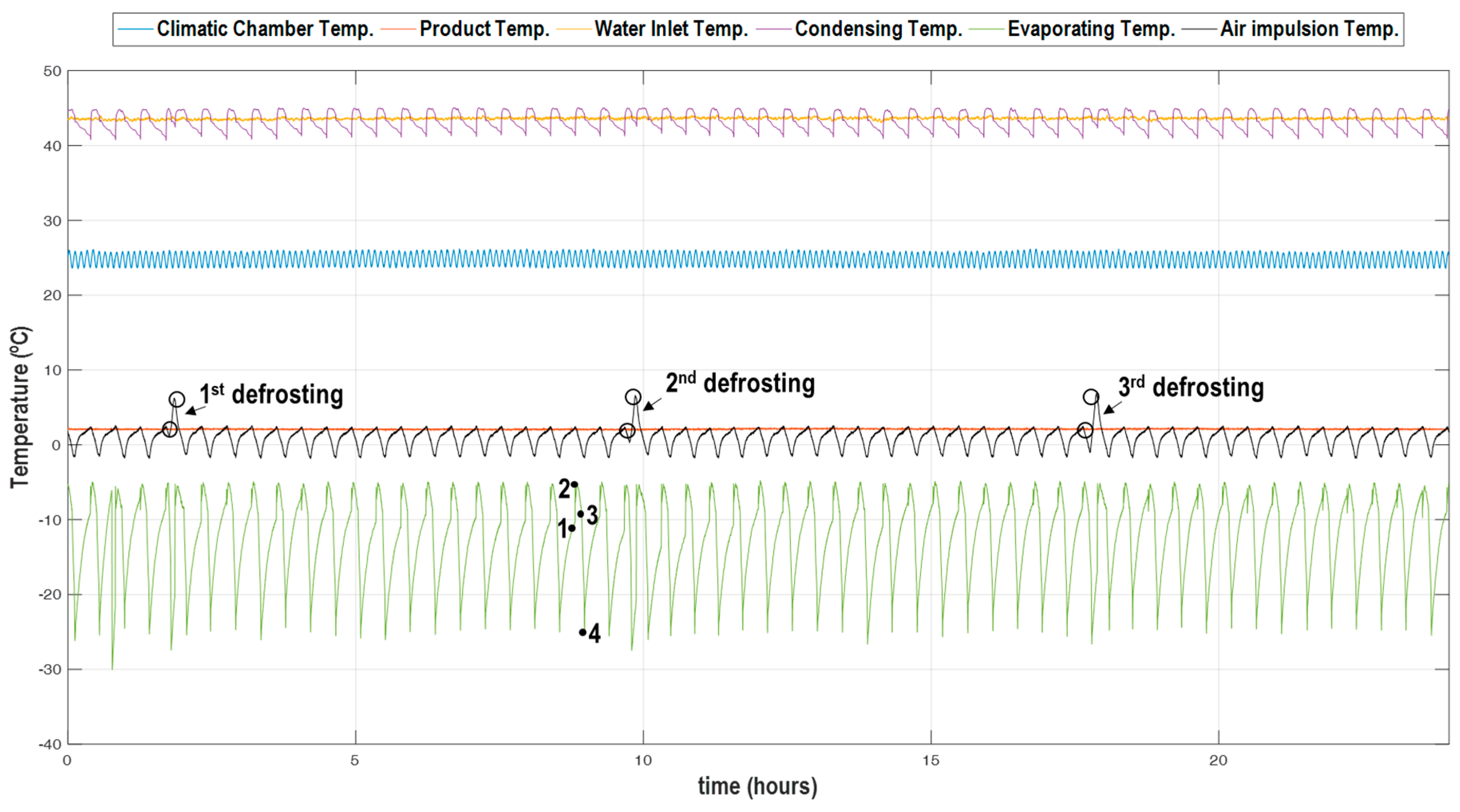
Figure 8 details the percentage of operating time during the 24-h tests of compressor and expansion valve for each layout for both refrigerants. The most significant effect than has been measured for both refrigerants is that the compressor operation fraction increases when using an indirect system. For this evaluation, the measured increment in compressor’s operation time has been between 17.8% and 20.7% for R-134a and between 6.2% and 11.8% for R-507A. The reason for this increment is that the amount of refrigerant contained in the distribution lines (liquid and vapour) and in the cabinet’s evaporator when using a direct expansion system is higher than when using an indirect system. In the direct expansion configuration, the amount of refrigerant contained in the system is higher, so the evaporation pressure rises slowly until the compressor is activated again. On the contrary, when using the indirect system, the amount of refrigerant contained in the secondary fluid heat exchanger is low, and therefore the low pressure increases rapidly and the compressor is activated more frequently. This effect can be observed by contrasting the evaporating temperatures in
Figure 3 (direct expansion) and in
Figure 4 (indirect expansion). It can be observed that the compressor enters into operation more frequently. Another important effect observed in
Figure 8 is that the operation time of expansion valve and compressor are decoupled when using a direct expansion system, again due to the amount of refrigerant contained in the distribution lines and in the cabinet’s evaporator, but they are coupled when using an indirect system.
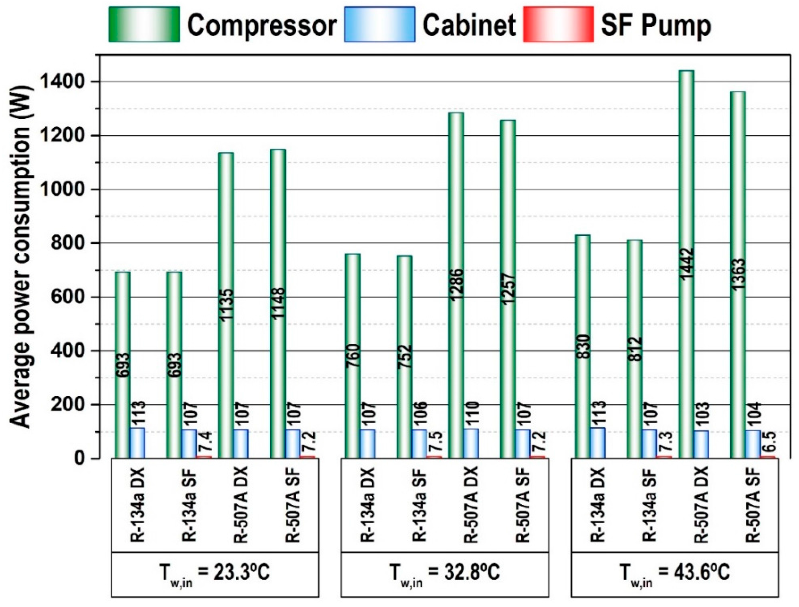
Figure 9 details the average power consumption of compressor (when it is in operation), of cabinet (including the three defrosting periods) and of secondary fluid pump during the 24-h tests. As can be observed, both the cabinet’s and the compressor’s power consumption remain practically constant for both refrigerants in direct expansion or indirect system. The maximum variation for R-134a is of 2% for the operation at 43.6 °C and of 5% for R-507A at 43.6 °C. Regarding the power consumption of the secondary fluid pump, it remains at a closer value, being negligible in relation to the compressor and cabinet.
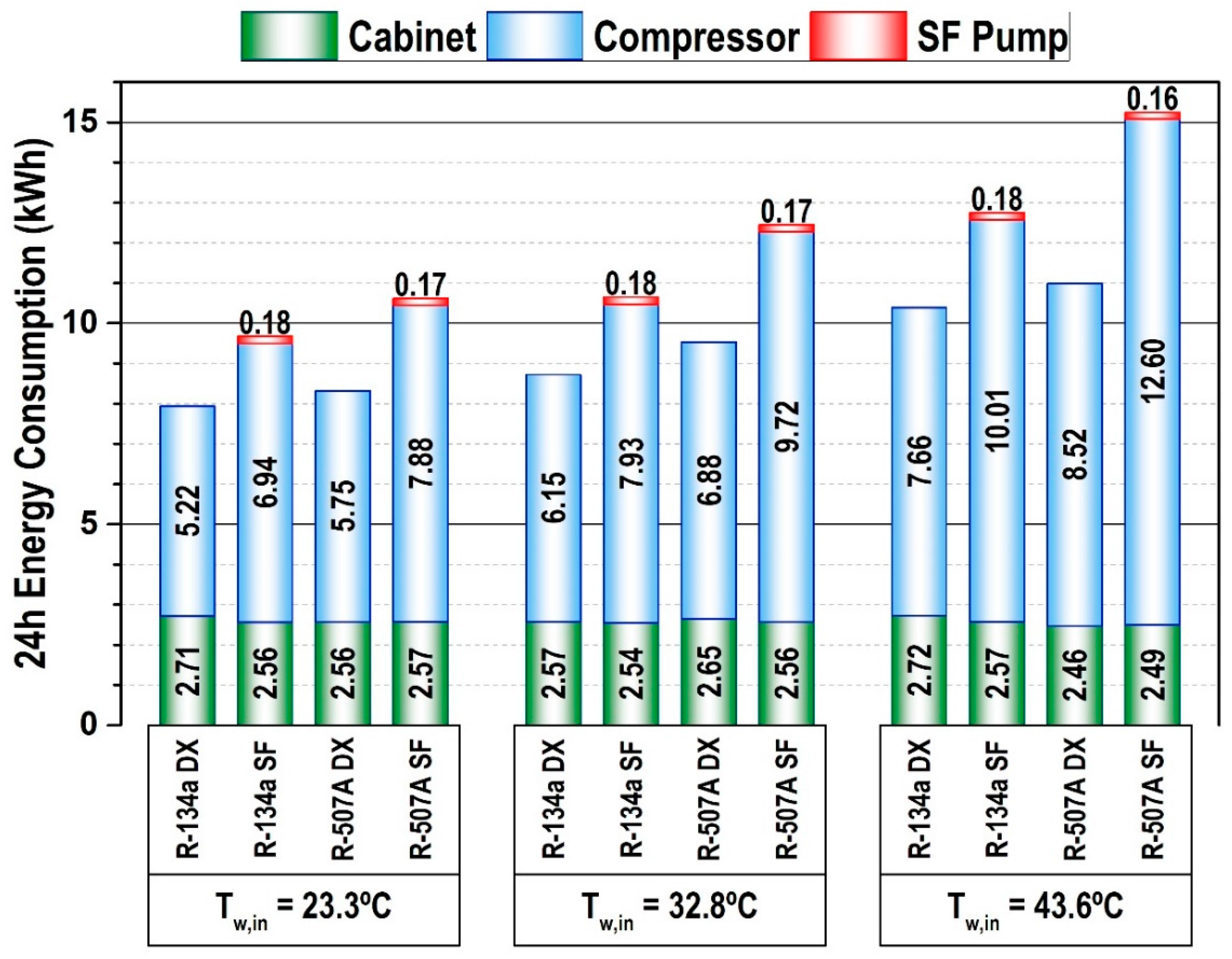
Finally, to compare the direct expansion and indirect configurations from an energy point of view, the energy consumption (kWh) of each element has been calculated from the power consumption measurements and operating time according to Equation (5) using a trapezoid integration method. In Equation (5), ‘i’ represents each energy consumer, ‘PC’ its power consumption and ‘j’ each sampled data. The expression is evaluated during the 24-h test.
The results are detailed in
Figure 10. Concerning cabinet’s energy consumption, no appreciable differences have been measured between the layout configurations and between both refrigerants. That indicates that the defrosting times are equivalent for both arrangements. In fact, the maximum deviation of defrosting times has been below 1 min for both refrigerants and both system layouts. Regarding the compressor’s power consumption, an important increment in its energy consumption has been measured when going from a direct to an indirect system, the main reason being the longer time that the compressor is in operation (
Figure 8). As can be observed, the increments in the compressor’s power consumption are most significant when operating with R-507A rather than with R-134a. Finally, regarding the secondary fluid pump power consumption, it remains invariable for all test conditions and refrigerants. It is important to note that its power consumption is insignificant in relation to the compressor and cabinet, but in larger systems this energy consumption could be larger.
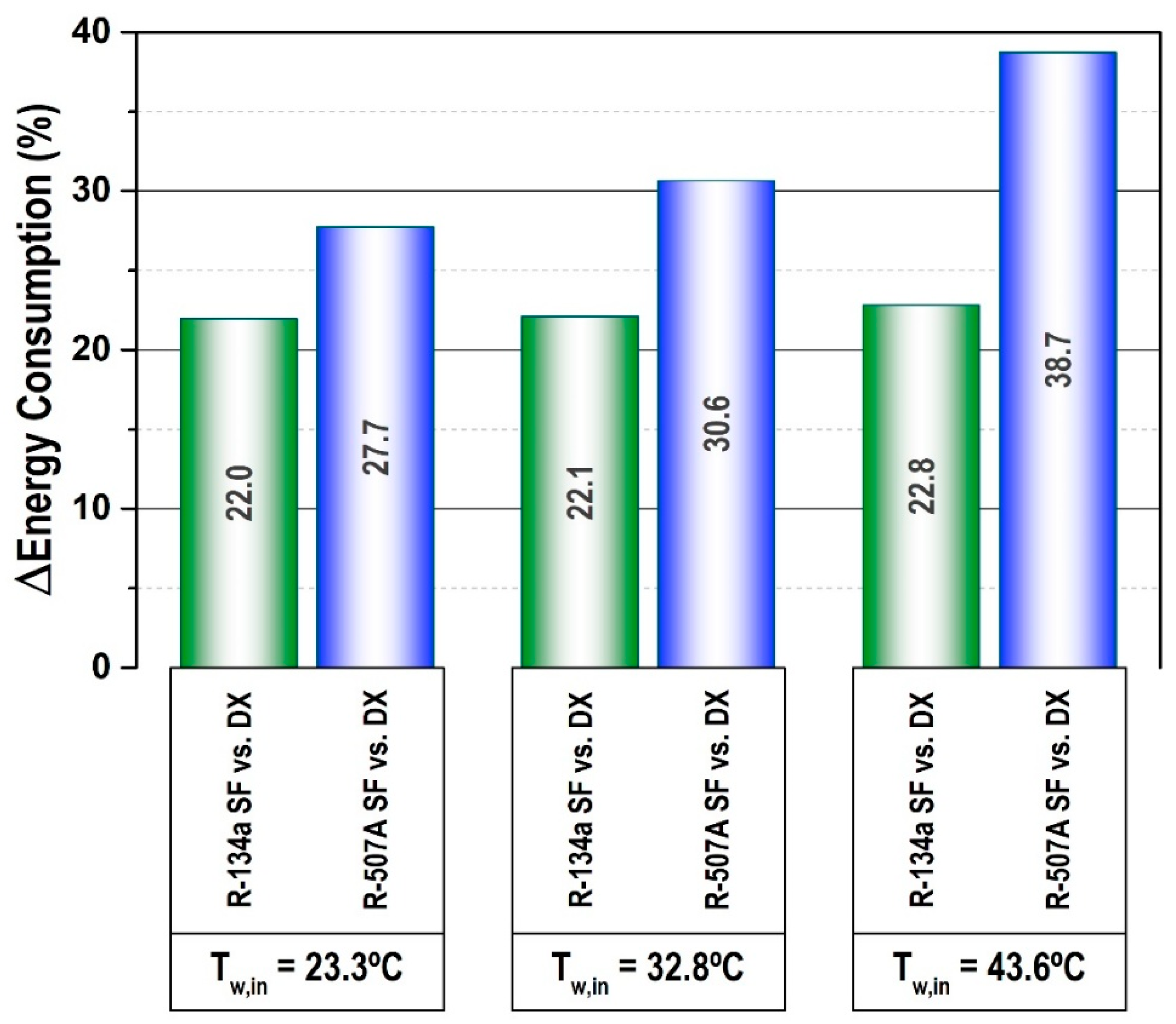
Finally, to contrast the energy effect of conversion of a direct expansion system to an indirect one,
Figure 11 represents the overall increment on energy consumption of the system for the three heat rejection levels. It includes the energy consumption of cabinet, compressor and secondary fluid pump during the 24-h test. As it can be observed, there is always a significant increment on the energy consumption when going to an indirect configuration, being it more significant when using R-507A as refrigerant. In this evaluation, the increments on energy consumption of the conversion for R-134a are of 22.0% at 23.3 °C, 22.1% at 32.8 °C and 22.8% at 43.6 °C when using R-134a, and of 27.7% at 23.3 °C, 30.6% at 32.8 °C and 38.7% at 43.6 °C when operating with R-507A. The increment on energy consumption for R-134a remains practically constant in a 22%, but for R-507A the increment in energy consumption is higher as higher the heat rejection level is.
4. Refrigerant Charge Reduction
As mentioned, the conversion of a direct expansion system to an indirect layout allows a large reduction in the refrigerant charge in the plant [
7,
9], thus helping reduce the direct impact of the refrigeration since leakages mainly occur in the distribution line fittings or in the evaporator of the cabinets.
To evaluate the refrigerant charge reduction that allows the conversion in the experimental plant used in this work, the highest heat rejection level (Tw,in = 43.6 °C) has been considered as a reference. The experimental refrigerant charges using the direct expansion system configuration for that condition were of 5.41 kg with R-134a and of 6.51 kg with R-507A. These refrigerant charges were the minimum that guaranteed the outlet line of the receiver would be filled with liquid refrigerant.
The refrigerant charge reduction that allows the system conversion can be evaluated using Equation (6). This equation evaluates the refrigerant charge reduction considering the refrigerant in the liquid and vapour distribution lines, and in the direct expansion evaporator of the cabinet. The average condensing and evaporating pressures (
Figure 5) and average outlet temperatures of condenser and evaporators (cabinet evaporator or SF evaporator) have been used to obtain the refrigerant density along the liquid and vapour lines. To compute the refrigerant charge in the evaporators, a mean void fraction of 85% has been considered, as recommended by Wedekind et al. [
26].
Table 4 summarizes the inner volumes of distribution lines and evaporators, as well as the refrigerant charge contained in those elements when operating with R-134a or R-507A. As can be seen, the major proportion of refrigerant is contained in the direct expansion evaporator and in the liquid distribution line. Finally,
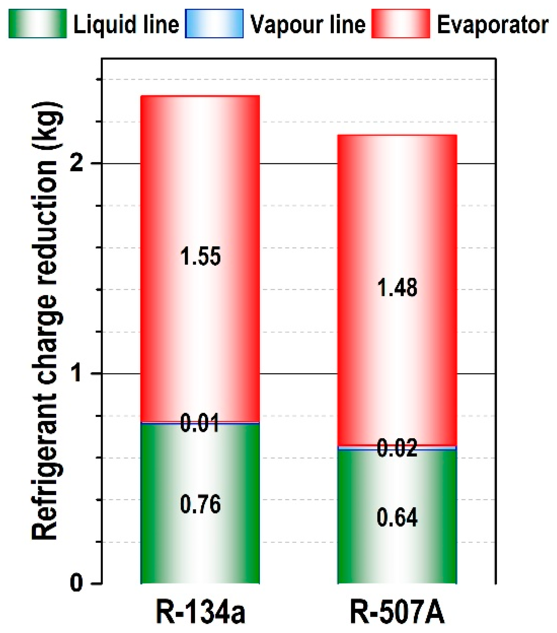
Figure 12 illustrates the refrigerant charge reduction obtained in the experimental plant when going from a direct to an indirect system. The main reduction occurs in the evaporator for both refrigerants, due to the large volume of this element in commercial cabinets, followed by the liquid distribution line. The reduction due to the vapour distribution line is insignificant. It needs to be mentioned that the refrigerant charge reduction in the liquid line in a large multiplexed refrigeration system would be larger due to the large distribution system.
In this case, taking as a reference the initial refrigerant charges of the plant, the conversion of this system to an indirect one allows a 42.9% refrigerant charge reduction when using R-134a as refrigerant and 32.8% with R-507A. It is important to highlight that the refrigerant charge reduction in a larger system would be higher.
5. Conclusions
This work analyses the energy impact of converting an R-134a or R-507A direct expansion refrigeration system to an indirect one using a medium temperature cabinet for fresh product. Systems were tested under laboratory conditions at a product temperature in the commercial cabinet of 2 °C at three water inlet dissipation temperatures (23.3, 32.8 and 43.6 °C), thus covering the common conditions of a supermarket. The experimental evaluation covered 24-h energy consumption tests.
From the experimental evaluation, it has been concluded that conversion to an indirect system provokes a reduction in the evaporating level to compensate for the additional heat transfer in the secondary fluid heat exchanger. This temperature reduction varies from 0.0 to 2.3 K for R-134a and from 0.0 to 2.9 K for R-507A. It has also been verified that the expansion valves operate with a reduced average degree of superheat in the indirect layout.
With respect to the working temperatures in the cabinet, both systems operated in a similar way, with the only exception being the average temperature of the heat exchanger of the cabinet. The use of the secondary fluid heat exchanger allowed for increasing the average temperature of this heat exchanger from 12.7 to 12.9 K with R-134a and from 16.1 to 21.3 K with R-507A. This temperature increment could have an influence on the defrosting periods; however, no appreciable differences were found in the experiment.
Regarding the energy evaluation during the 24-h tests, no appreciable differences were found in the average power consumption of cabinet and compressor between the two system layouts; however, large increments were measured in the operation time of the compressor. For R-134a it increased between 17.8% and 20.7% and for R-507A between 6.2% and 11.8%. That resulted in an overall increment in the energy consumption of the system when moving to an indirect configuration, varying between 22.0% and 22.8% for R-134a and between 27.7% and 38.7% for R-507A.
Finally, the experimental refrigerant charge reduction of the conversion of this system to an indirect layout was 42.9% for R-134a and 32.8% for R-507A.
Accordingly, it can be concluded that the conversion from a direct expansion system to an indirect configuration will reduce to a large extent the refrigerant charge of the system; however, the energy impact of using a secondary fluid indirect system is large, and therefore both aspects must be taken into consideration when proposing the conversion.


