Review

Light Scattering by a Dielectric Sphere: Perspectives on the Mie Resonances

Department of Electronics and Nanoengineering, Aalto University, Maarintie 8, 02150 Espoo, Finland
*
Author to whom correspondence should be addressed.
Appl. Sci. 2018, 8(2), 184; https://doi.org/10.3390/app8020184
Submission received: 15 December 2017 / Revised: 9 January 2018 / Accepted: 10 January 2018 / Published: 26 January 2018
(This article belongs to the Special Issue Nanophotonics)

Abstract

:
Light scattering by a small spherical particle, a central topic for electromagnetic scattering theory, is here considered. In this short review, some of the basic features of its resonant scattering behavior are covered. First, a general physical picture is described by a full electrodynamic perspective, the Lorenz–Mie theory. The resonant spectrum of a dielectric sphere reveals the existence of two distinctive types of polarization enhancement: the plasmonic and the dielectric resonances. The corresponding electrostatic (Rayleigh) picture is analyzed and the polarizability of a homogeneous spherical inclusion is extracted. This description facilitates the identification of the first type of resonance, i.e., the localized surface plasmon (plasmonic) resonance, as a function of the permittivity. Moreover, the electrostatic picture is linked with the plasmon hybridization model through the case of a step-inhomogeneous structure, i.e., a core–shell sphere. The connections between the electrostatic and electrodynamic models are reviewed in the small size limit and details on size-induced aspects, such as the dynamic depolarization and the radiation reaction on a small sphere are exposed through the newly introduced Mie–Padé approximative perspective. The applicability of this approximation is further expanded including the second type of resonances, i.e., the dielectric resonances. For this type of resonances, the Mie–Padé approximation reveals the main character of the two different cases of resonances of either magnetic or electric origin. A unified picture is therefore described encompassing both plasmonic and dielectric resonances, and the resonant conditions of all three different types are extracted as functions of the permittivity and the size of the sphere. Lastly, the directional scattering behavior of the first two dielectric resonances is exposed in a simple manner, namely the Kerker conditions for maximum forward and backscattering between the first magnetic and electric dipole contributions of a dielectric sphere. The presented results address several prominent functional features, aiming at readers with either theoretical or applied interest for the scattering aspects of a resonant sphere.

1. Introduction

Light scattering and absorption by a single sphere, i.e., electromagnetic radiation, is a widely studied canonical problem encountered in both applied and theoretical sciences, such as material and optical physics [1,2,3,4,5], chemistry [6,7], nanotechnology [5,8], radio/antenna engineering [9,10], and applied mathematics [11]. The sphere is one of the few three-dimensional bounded geometrical shapes that possess a closed-form analytical solution either in the electrostatic or the electrodynamic domain (Here we assume a small-to-intermediate sized sphere with respect to the incident wavelength. Treatments of larger spheres in the geometrical optics approximations are beyond the scope of this short review, see for example [12]). Thus, a sphere can be arguably perceived as an archetype of a scatterer for the extraction of valuable insights regarding the scattering problem by bounded objects. It is commonly used as a reference for any kind of electromagnetic scattering theory [13] and applications, from the utilization on experimental setups [7] to the benchmarking of computational methods [14,15] and beyond.
The twentieth century witnessed the birth of many, now-classical, text-books dealing with light scattering spheres, offering thorough, instructive, and wide discussions on the subject and its treatments. Workers such as Stratton [16], van de Hulst [17], Kerker [18], and Bohren and Huffman [19] are only some of the contributors to this tradition, delivering complete and educative perspectives on this subject. Indeed, the number of books and contributors on this subject is very large. It is appropriate to acknowledge that this is just an indicative and not comprehensive textbook list. For a more complete list, one can follow the suggested textbooks and the references therein. An eloquent historical retrospective for the research up to the 1970s is given by Milton Kerker in his book on light scattering [18].
Nonetheless, the significance of such a long-standing problem with solidly established theory resonates up to our modern times, opening new avenues for the understanding of fundamental scattering and absorptive phenomena. A stark example is the recent identification of Fano interference line-shapes appearing on the scattering spectrum of a sphere [20,21,22,23]. Recent research trends, such as the metamaterial/metasurfaces paradigm [24,25,26], and the plasmonic or all-dielectric energy control/harvesting devices [4,5,8,26,27,28,29,30,31,32,33] enabled the extensive use of a sphere as a fundamental testbed purposes. Likewise, the conceptual demonstration/realization of single particle devices, such as sensors [34,35], electromagnetic cloaks [36,37,38,39,40], “super”-scatterers [41], optical force carriers [42], and optical memory devices [43], are nothing but different perspectives on the scattering response of a spherical inclusion, and new light control/harvesting functionalities are attributed to the emerging collective effect of a suspension of spherical scatterers [2,8,25,44]. It is therefore evident that the spherical scattering particles are in the core of modern electromagnetics and optics research.
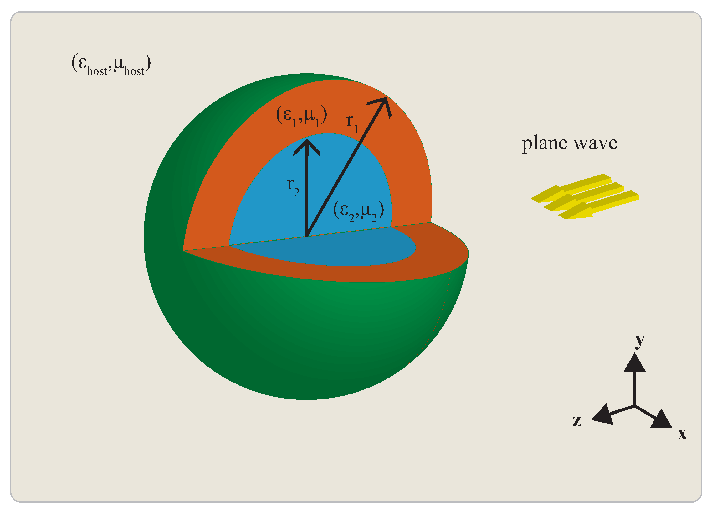
In this review, some of the most basic features of its resonant scattering behavior are exposed, covering the two most prominent features of a resonant sphere: the plasmonic and the dielectric resonances. To start with, let us assume a sphere of radius r 1 subject to an incident monochromatic plane wave of wavelength λ , as can be seen in Figure 1, where the time-harmonic convention e i ω t is assumed. The sphere consists of a homogeneous and isotropic material of given permittivity (dielectric constant) ε 1 and permeability μ 1 , immersed in a host medium with relative parameters ( ε host , μ host ) . Note that all material parameters are normalized with respect to the permittivity and permeability of vacuum, ε 0 , μ 0 . The electrical size is expressed through the size parameter defined as x = ω ε host ε 0 μ host μ 0 r 1 = 2 π λ r 1 , where ω ε host ε 0 μ host μ 0 = k is the wavenumber of the host medium. The first, mathematically rigorous attempts explaining the triggered mechanisms, therefore quantifying the scattering behavior, were derived by Lord Rayleigh for the case of a very small scatterer (electrostatic case) [45,46,47]. Almost simultaneously, developments attributed to workers such as Thomson, Love, Lorenz, Debye, and Mie gave birth to a more complete electrodynamic perspective about this problem, always in accordance with the Maxwell equations [18,48].
In both aforementioned cases, the mathematical treatment of the problem is similar: assuming a plane wave excitation and requiring that both outside and inside regions Maxwell’s equations are satisfied, one can derive a set of electrical and magnetic field expressions, expanded in the spherical coordinate system [16,49]. These expressions contain a set of unknown amplitude coefficients, the Mie coefficients [19]. The determination of these coefficients requires the solution of the formulated boundary value problem, i.e., the continuity of all tangential field components at the interface (or interfaces if we have multilayered sphere), assuming that the acceptable solutions consist of properly behaving functions that vanish at infinity and are well behaved in the origin of the sphere. A complete and systematic analysis for this problem can be found in several text-books [16,18,19].
Here, we will try to unravel the resonant features of the Mie coefficients and analyze their physical implications. Section 2 conveys a brief discussion on the full-electrodynamic scattering perspective, the Mie coefficients, where the spectrum of a homogeneous dielectric sphere as a function of the permittivity and the size parameter is given. The study of the scattering spectrum reveals the existence of two different resonant features, the localized surface plasmon (LSPR or plasmonic) and the dielectric resonances, respectively. Plasmonic resonances (LSPRs are generally different from their surface and volume counterparts, since LSPRs are non-propagating resonances, directly triggered by the impinging radiation [50]) occur from the coupling between the free electrons (plasma, ε < 0 ) in metals with the electromagnetic field [50,51]. This collective effect involves both the electric and kinetic energy of the free electrons, hence is of primarily electric character and can be observed even for deeply subwavelength structures [52]. However, the second type of resonances, i.e., the dielectric resonances, are of either magnetic or electric character, highly dependent on the dielectric contrast of the sphere. The dielectric resonances exhibit a more complicated field distribution inside the scatterer. These resonances are also called morphology-dependent resonances (MDR) [53], or Mie resonances [4] occurring for ε > 0 .
In Section 3, a brief description of the electrostatic (Rayleigh) problem is given, exposing the nature of the plasmonic resonances on a subwavelength sphere. A connection between the Rayleigh picture and the plasmon hybridization is briefly discussed for the case of a resonant core–shell sphere. Section 4 begins with a revision of the Mie–Taylor approximation, an alternative way to reach the Rayleigh picture, offering a clear connection between the electrostatic and the Mie theory perspective. A more complete picture encompassing the resonant features of the Mie coefficients, i.e., size-induced dynamic characteristics, is obtained by the Mie–Padé approximation. Valuable information regarding these scattering processes are extracted, and generalized resonant formulae of the resonant magnetic and electric multipoles are exposed in Section 5. Finally, in Section 6, we expose features regarding the directive scattering characteristics of a sphere; predictions for the maximum forward and backscattering, namely the Kerker conditions, are given, followed by concluding remarks for the light scattering characteristics of a sphere.

2. Electrodynamic Scattering: Mie Coefficients

As discussed in the introductory section, the scattering problem by a sphere subject to a plane wave has been rigorously solved by following the aforementioned assumptions. The key concepts are the Lorenz–Mie (or simply Mie) coefficients that rigorously quantify the material and size contributions to the overall scattering behavior. These coefficients are described by a set of fractional functions consisting of spherical Bessel, Hankel, and Riccati–Bessel and Riccati–Hankel functions, viz.,
a n = m 2 j n ( m x ) x j n ( x ) μ 1 j n ( x ) m x j n ( m x ) m 2 j n ( m x ) x h n ( 1 ) ( x ) μ 1 h n ( 1 ) ( x ) m x j n ( m x )
b n = μ 1 j n ( m x ) x j n ( x ) j n ( x ) m x j n ( m x ) μ 1 j n ( m x ) x h n ( 1 ) ( x ) h n ( 1 ) ( x ) m x j n ( m x )
where a n and b n denote the electric and magnetic coefficients, respectively [19]. The size parameter, x = k a , is a function of the sphere’s radius a and host medium wavenumber; ε 1 and μ 1 are the sphere’s material parameters. Finally, m = ε 1 μ 1 ε host μ host is the contrast parameter. Similar expressions are also available for the case of core–shell structures [54], while iterative relations of the Mie coefficients can be found for the case of n-layered structures [55]. Likewise, cases of inhomogeneous [56,57] or anisotropic inclusions [58,59] are available, being, however, beyond the scope of this review.
The Mie coefficients can also describe the energy balance between the different mechanisms on a sphere: scattering and absorption. A common way for expressing these energies is by looking the far-field characteristics, i.e., the scattering and extinction (scattering + absorption) efficiencies. These efficiencies can be expressed as a combination of the Mie coefficients, i.e.,
Q sca = 2 x 2 n = 1 2 n + 1 a n 2 + b n 2
and
Q ext = 2 x 2 n = 1 2 n + 1 { a n + b n }
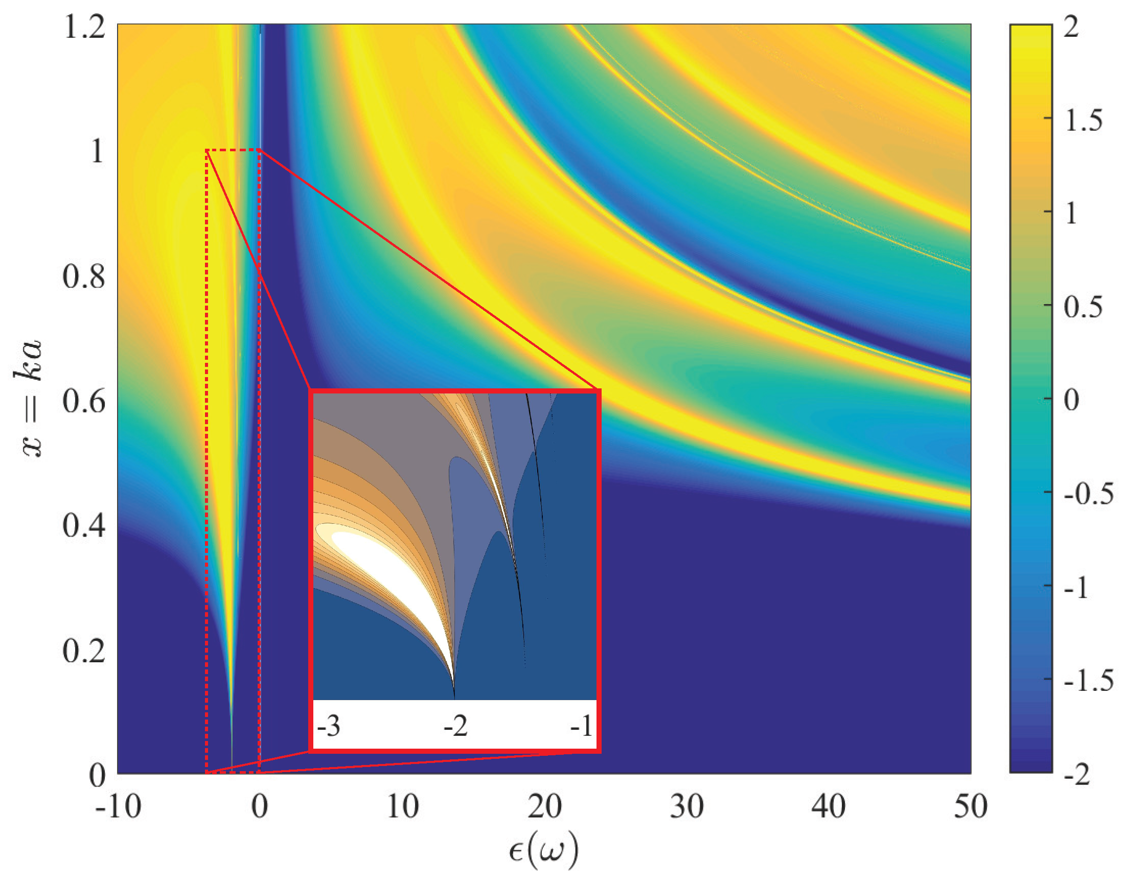
as can be found in text-books [9,18,19]. Figure 2 depicts the scattering efficiency spectrum as a function of both ε 1 and x. We can observe several lines of radiation enhancement in both plasmonic ( ε 1 < 0 ) and dielectric ( ε 1 > 0 ) region, respectively. In the computation of Figure 2 the infinite sum of Equation (3) has been truncated in accordance to the Wiscombe’s criterion, that correlates the sufficient number of modes with the size parameter of the sphere [60].
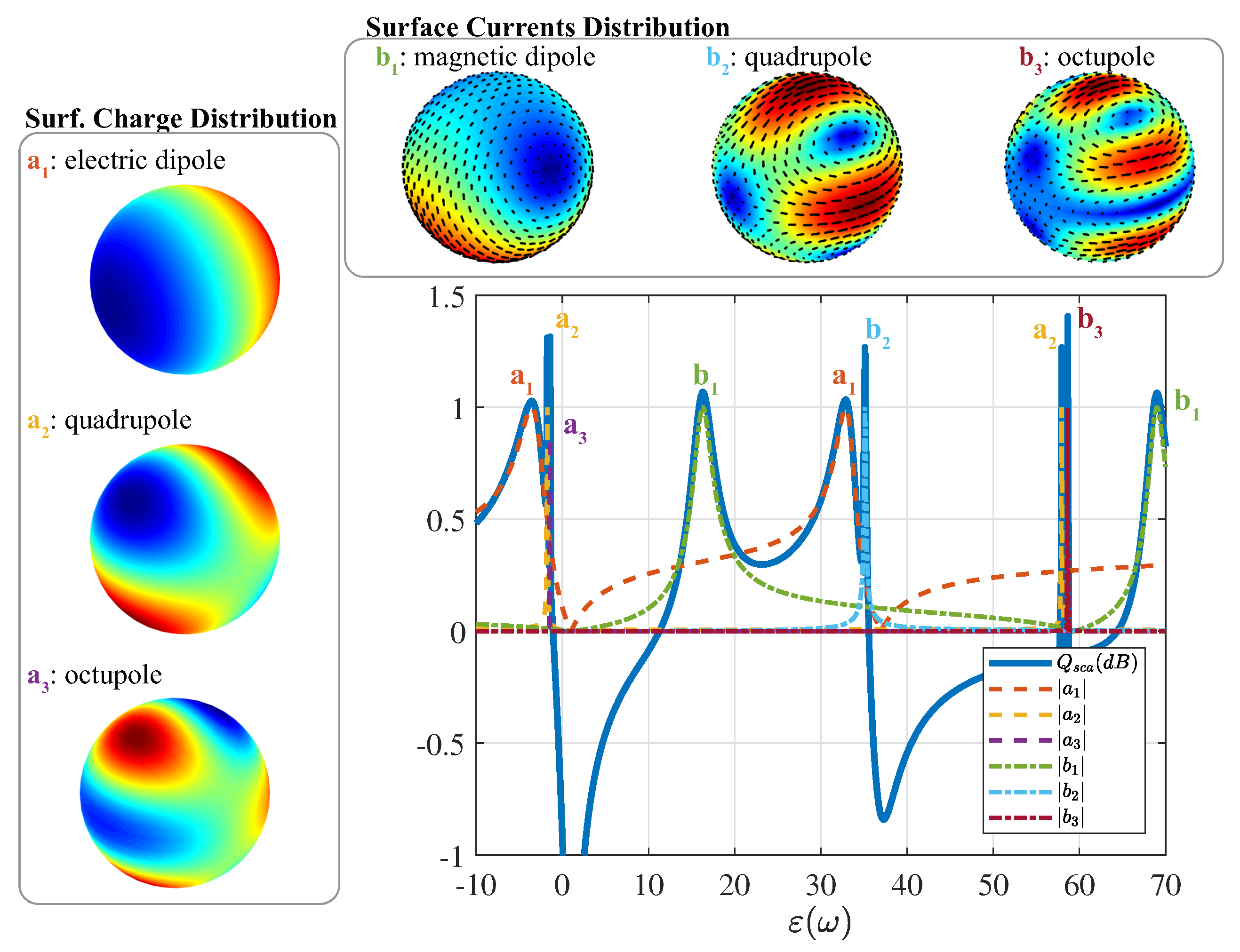
The plasmonic region resonances correspond to the enhancement of the electric Mie coefficients, a n , while the dielectric region exhibits both magnetic b n and electric a n resonances. This fact is depicted in Figure 3, where the scattering efficiency and the first three magnetic and electric Mie coefficients are visible, for a given size parameter ( x = 0.75 ). The inset figures depict the charge and surface current distribution for the a 1 , a 2 , a 3 and b 1 , b 2 , b 3 coefficients, respectively. It is evident that the magnetic coefficients exhibit pronounced circulating charge distributions, resembling in such manner the magnetic dipole, quadrupole, and octupole configurations. Actually, this is particularly interesting phenomenon that enables the magnetic response of a dielectric sphere the optical and near-infrared regime, where magnetic materials are not traditionally available [61,62]. Likewise, for the electric coefficients the surface charge accumulates in a dipolar, quadrupolar, and octupolar manner. Note that both plasmonic and dielectric electric resonances exhibit the same surface strength and charge distribution.

3. Electrostatic Scattering by a Sphere

A standard way to analyze subwavelength plasmonic resonances is by implementing an electrostatic scattering picture for the proposed problem. The analysis can be seen as the perturbation that a spherical object causes on a constant electric field. The formulated model can be expressed as a boundary value problem for the following quantities: the external potential, Φ inc = E 0 r cos θ , the perturbed (scattered) potential Φ sca = B 0 r 2 cos θ and the internal potential Φ in = A 1 r cos θ . The boundary problem requires the continuity of the tangential field and normal flux density on the boundary, i.e., Φ out ( r , θ ) = Φ in ( r , θ ) , at r = r 1 and ε host r Φ out ( r , θ ) = ε 1 r Φ in ( r , θ ) at r = r 1 . The resulted scattering amplitudes, B 0 and A 0 , read
B 0 = ε 1 ε host ε 1 + 2 ε host E 0 r 1 3
and
A 1 = 3 ε host ε 1 + 2 ε host E 0
The proportionality constant of the dipolar scattering amplitude, B 0 , is commonly recognized as the normalized polarizability of the inclusion [64], viz.,
α = 3 ε 1 ε host ε 1 + 2 ε host
Its form reveals an interesting property, the field enhancement around the value ε 1 = 2 ε host , known as polarization enhancement of Fröhlich frequency [65,66]. A very informative section can be found in Bohren and Huffman (in [19], Section 12.1). Actually, the general rule describing the resonant condition of each n-th multipole term, i.e., ε 1 = 2 ε host (dipole), ε 1 = 3 2 ε host (quadrupole), etc., reads
ε 1 = n + 1 n ε host
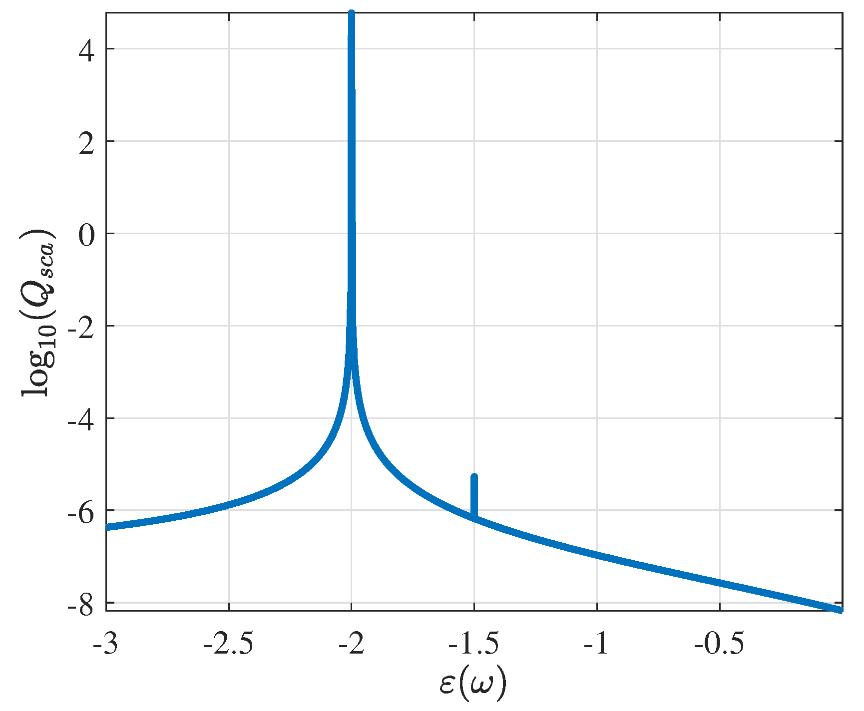
Figure 4 illustrates the scattering efficiency of an extremely small sphere ( x = 0.01 ), where two main plasmonic resonances are visible. The position of these resonances is described by the condition found in Equation (8).
Assuming an ideal lossless Drude-like material, i.e., ε ( ω ) = ε ω p 2 ω 2 , the resonant condition of a solid sphere is met when
ω 2 = ω p 2 ε + 2 ε host
often also called the symmetric (bonding) resonance of a sphere [1]. A realistic Drude-like material includes also an imaginary damping term, i.e., ε 1 ( ω ) = ε ω p 2 ω 2 + i γ ω [50,51]. This model gives the free-electron description inside metals, such as gold or silver [67], and it is extensively used for the analysis of plasmonic resonances. For this type of materials, negative values for the real part of the permittivity occur. Hence, the above plasmonic resonance can be captured by the simple electrostatic model presented above. A very important conclusion is that these resonances can in principle occur even for deeply subwavelength sizes of the scatterer. This is the reason why plasmonic resonances are particularly attractive for the localization of energy even far below the diffraction limit [50]. Note that the resonant properties are here studied as a function of the permittivity; for the response of a sphere comprising a realistic material model, such as Au or Ag, see, for example, [6,14,67], and the references therein.
The polarizability of a complementary structure, i.e., a spherical cavity of permittivity ε host surrounded by a material of ε 1 permittivity, occurs by the mutual exchange between ε host ε 1 on Equation (5). As a result, the resonant condition is ε 1 = ε host 2 , or
ω + 2 = 2 ω p 2 2 ε + ε host
known also as the antisymmetric (antibonding) resonance [1]. It is interesting to note that all plasmonic resonances occur at the negative permittivity range, i.e., a necessary condition for the existence of such resonances [68,69].
The combination of a solid sphere and spherical cavity naturally delivers the case of a core–shell sphere, as depicted in Figure 5. Following a similar electrostatic analysis as before (see for example [70,71]) the polarizability of a core–shell spherical inclusion reads
B 0 = C ε 1 ( ω ) ε host C ε 1 ( ω ) + 2 ε host r 1 3 E 0
where
C = 2 + 3 1 1 ε 2 ε 1 ε 2 + 2 ε 1 η 3
where η = r 2 r 1 is the radius ratio. The coefficient C is a function of a the term ε 2 ε 1 ε 2 + 2 ε 1 η 3 , resembling the polarizability of a solid sphere of permittivity ε 2 (core material) immersed into a host medium of permittivity ε 1 (shell material).
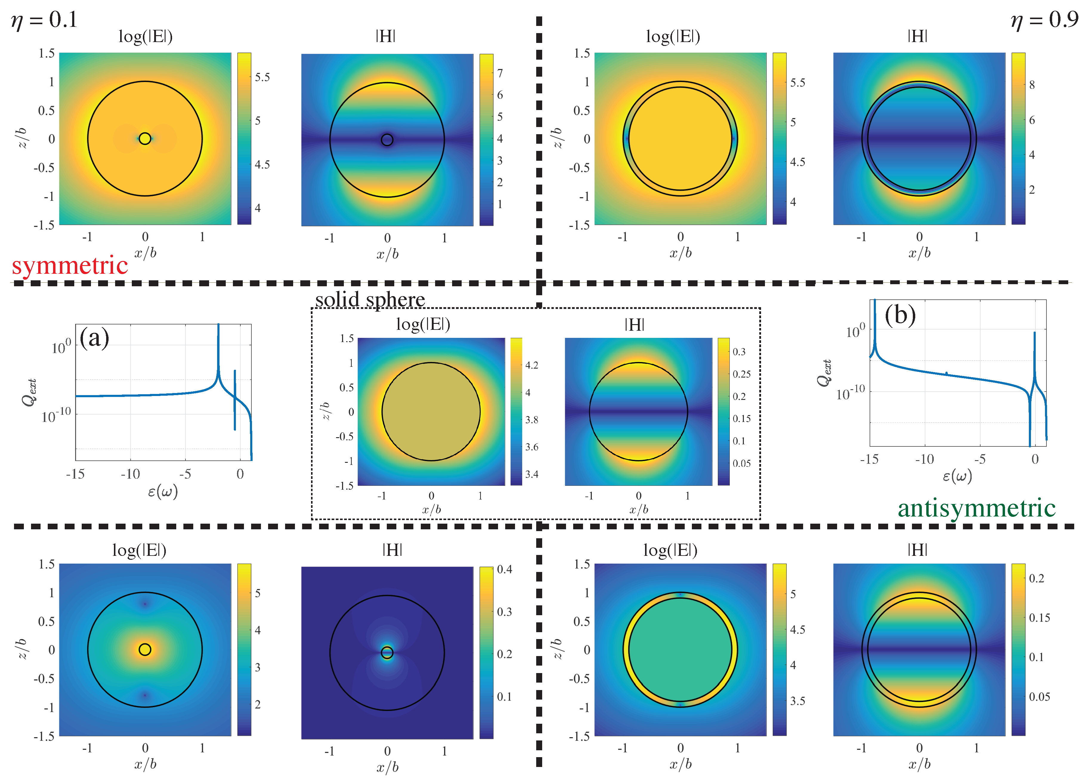
This formula suggests the appearance of one additional pole and the creation of a zero to the overall system response, directly influenced by the volume ratio between the two regions. In Figure 6, we can observe these effects for both thick ( η = 0.1 ) and thin ( η = 0.9 ) shells. The field distributions for both symmetric and antisymmetric resonances are presented, illustrating the main character of the resonances. Obviously, the case ε 1 = ε 2 leads to C = 1 , collapsing to the homogeneous case of Equation (5). A complete discussion regarding the pole conditions with respect to the core and host medium can be found in [72].
Following the same, Drude-like philosophy as before (assuming ε 2 = 1 ), the case of a spherical hollow core–shell structure, after some calculations, gives the following two resonant conditions
ω ± 2 = ω p 2 2 1 ± 1 3 1 + 8 η 3
corresponding to the first two, symmetric and antisymmetric dipolar-like resonances of a hollow core–shell sphere. A generalization that includes the higher order multipoles can be found in [73]
ω n ± 2 = ω p 2 2 1 ± 1 2 n + 1 1 + 4 n n + 1 η 2 n + 1
where ω n + 2 and ω n 2 is the symmetric and antisymmetric resonances for a given background frequency (plasma frequency) ω p and a given multipole, i.e., dipole ( n = 1 ), quadrupole ( n = 2 ) and so on [74]. Note that the multilayered case can be generalized in an analogous manner, as can be readily found in [70].
It is interesting to observe that Equation (13) reduces to Equation (9) for a solid sphere and Equation (10) for a spherical cavity. Therefore, the existence of symmetric and antisymmetric resonances is attributed to a hybridization scheme between the plasmonic resonances appearing in both structures, the solid sphere and the spherical cavity. A complete physical interpretation behind this hybridization model can be found in a series of articles by Prodan, Nordlander, and others [1,75,76]. It is remarkable to notice that the plasmonic resonances are extensively useful for a wide range of applications, such as sensors [34], photovoltaics [2], and more exotic electro-optical applications [29] where localization of energy is required beyond the diffraction limit.

4. Taylor and Padé Expansions of Mie Coefficients

It is rather obvious that the aforementioned straightforward but complicated Mie coefficients (Equations (1) and (2)) cannot actually offer direct physical interpretation on the studied problem, mostly due to their mathematical form. Several remedies have been proposed based on approximative methods, such as the Taylor expansion of the Mie coefficients [53,60,71,77,78,79,80,81], the Weierstrass approximation [82], and the Padé approximation [63,83,84,85]. The main objective of this section is to review some simple, yet intuitive, expressions regarding the dependencies governing the behavior of the Mie coefficients by expanding both a n and b n in a Taylor (Mie–Taylor) and Padé (Mie–Padé) manner. A short analysis for the position and width of the resonances, as well as the depolarization and radiative damping processes will be given as a function of the size parameter for both plasmonic and dielectric resonances.
We begin by approximating Equations (1) and (2) with a Taylor series expansion for small x, i.e.,
a 1 T i 2 3 ε 1 1 ε 1 + 2 x 3 i 1 5 ε 1 2 ( 1 + μ 1 ) 6 ε 1 + 4 ( ε 1 + 2 ) 2 x 5 + O [ x ] 6
b 1 T i 2 3 μ 1 1 μ 1 + 2 x 3 i 1 5 μ 1 2 ( 1 + ε 1 ) 6 μ 1 + 4 ( μ 1 + 2 ) 2 x 5 + O [ x ] 6
A similar type of expressions can be readily found in many textbooks [16,18,19], and are valid for a general homogeneous sphere possessing both magnetic and dielectric properties. In the case of a magnetically inert ( μ 1 = 1 ) sphere, the above terms reduce to a much simpler form, viz.,
a 1 T i 2 3 ε 1 1 ε 1 + 2 x 3 i 2 5 ( ε 1 2 ) ( ε 1 1 ) ( ε 1 + 2 ) 2 x 5 + O [ x ] 6
b 1 T i 1 45 ( ε 1 1 ) x 5 + O [ x ] 7
The first term of the electric Mie coefficient represents the extracted polarizability for the electrostatic problem. Therefore, by truncating the orders higher than x 3 , we deduce that
a 1 T = i 2 9 α x 3
implying that the first Mie coefficient contains the same polarization enhancing character as the electrostatic polarizability.
Although the Taylor expansion delivers a straightforward connection with the electrostatic problem, and therefore with the plasmonic enhancement, it offers very little insight regarding the dielectric resonances. This can be explained by the fact that the dielectric resonances asymptotically occur at extremely large permittivity contrast values for small spheres, as can be seen in Figure 2. Likewise, Equation (18) does not capture any resonances (poles of a system). Therefore, an alternative approximation stratagem is necessary to gain these pieces of information. The form of a n and b n suggests the usage of a rational approximation capable in describing all features of the modeled system (zeros and poles). Such expansions, fulfilling all the above requirements, are the Padé approximants.
The Padé approximants are a special type of rational approximation constructed by expressing a function in a rational form and expanding each of the rational terms in power series [86,87]. Here, the Padé expansion that corresponds to the fractional expression of two polynomials P ( x ) Q ( x ) of order x L and x M , is denoted as [ L / M ] , following the notation of [86]. As an example, a set of Padé approximants for the spherical Bessel and Hankel functions can be found in Table A1.
Although the application of the Padé approximants for scattering problems was previously utilized for the Rayleigh regime [83,84], recent studies shed light on the scattering phenomena in a systematic way, especially with respect to the resonant conditions and other enabled mechanisms [63,72,85]. In this section, we briefly summarize references [63,72,85] and the results found therein.
As a first example, the [ 3 / 3 ] Padé expansion for a 1 reads
a 1 P i 2 3 ε 1 1 ε 1 + 2 x 3 1 3 5 ε 1 2 ε 1 + 2 x 2 i 2 3 ε 1 1 ε 1 + 2 x 3
We note that Equation (20) can be decomposed into three distinctive parts. First, the ε 1 1 ε 1 + 2 is the normalized static polarizability term, similarly with Equation (15). This term contributes a system pole at ε 1 = 2 only for the static case [88]. The second part is ε 1 2 ε 1 + 2 x 2 that introduces the size effects over the coefficient and to the overall scattering procedure, and thus it is recognized as the dynamic depolarization term [89]. Lastly, the imaginary term of order x 3 in the denominator is recognized as the radiative damping part. For the lossless case ( ε = 0 ), this part prevents the coefficient from infinite growth and represents the intrinsic radiative damping/reaction mechanism of the scattering process [46,49,90]. Ignoring the dynamic depolarization term in Equation (20) and utilizing the expression (19) we observe that
a 1 [ 3 / 3 ] = a 1 T 1 + a 1 T = i 2 9 α x 3 1 i 2 9 α x 3
This is an equivalent expression of the polarizability model that includes the induced radiative reaction on the single subwalength scatterer, as has been repeatedly exposed by many workers [6,46,89,90,91,92,93,94].
Expression (20) exhibits a pole (resonance) at ε 1 = 2 15 i + 9 i x 2 5 x 3 15 i 9 i x 2 + 10 x 3 , which gives, for small x
ε 1 = 2 12 5 x 2 ( 1 + 3 5 x 2 ) 2 i x 3 ( 1 + 7 5 x 2 ) +
As before, the resonant condition contains a static term ( 2 ), a dynamic depolarization term ( x 2 ), and a radiative damping imaginary term ( x 3 ). Note that, for an open resonator, the resonant frequencies should be generally complex, known as natural frequencies [16]. Again, the real terms of Equation (22) represent the shift that the position of the resonance exhibits with respect to the size. However, the imaginary term dictates also both the width of the resonance and the amount of losses required in order to maximize the absorption. The latter can be seen as a form of a conjugate matching between the incident wave and the scatterer [20,63,95,96,97],
Let us now apply the same Padé stratagem for the magnetic coefficient b n . The [ 5 / 5 ] Padé expansion of the first magnetic dipole coefficient b 1 reads
b 1 P i ε 1 1 45 x 5 1 + 1 21 ( 5 2 ε 1 ) x 2 + [ x 4 ] i 1 45 ( ε 1 1 ) x 5
with the truncated term being
[ x 4 ] = ε 1 2 + 100 ε 1 125 2205 x 4
Interestingly, expression (23) gives a resonant condition that yields to the value
ε 1 = 2.07 + 10.02 x 2 + 1.42 x 2 2 i x 1.06 0.77 x 2
where the accuracy was kept up to the second decimal. The condition (25) predicts, in contrast to the Taylor–Mie example, a pole for the magnetic dipole coefficients, suggesting a clear intuitive picture regarding the nature of the magnetic resonances enabled on a dielectric sphere. First, the pole condition in Equation (25) suggests an inverse square dependence, showing that the magnetic resonance for small spheres can be reached only for large contrast materials, making the observation of this kind of resonances for very small spheres practically impossible. Secondly, a constant term appears, regulating slightly the real part of the pole condition. Lastly, the radiative damping process (imaginary part) of a magnetic dipole does not follow the same volume dependence ( x 3 ) observed in the previous electric dipole case (Equation (22)), but rather a linear x dependence [85].
At this point, it is obvious that the Padé–Mie approximants of small order give information regarding the plasmonic and dielectric magnetic resonances. However they do not expose much of information about the third type of resonance, associated with the dielectric electric multipoles. Intuitively, Padé approximants of higher order can expose additional poles. Therefore, we next evaluate higher order approximants for a 1 . Note that the Padé expressions of these expansions are lengthy, and full expansions will be omitted.
For instance, the [ 7 / 2 ] expansion of the a 1 coefficient gives in total four poles, one corresponding to the plasmonic case, two non-observable double complex roots, and a fourth yielding the following expression
ε 1 [ 7 / 2 ] = 14.5 + 22.5 x 2 + i 77.778 x +
where the superscript indicates the order of the used Padé approximant.
This first pole condition demonstrates the same inverse square size dependence observed in Equation (25). Here, the radiative damping term is extremely large, an indication that a more accurate, higher order expansion is needed. To do so we increase the order of the numerator, keeping the denominator order as low as possible. By this, straightforward, and numerically convenient heuristic method, we are able to identify more accurately any of the pole conditions. After several iterations, the [ 19 / 2 ] Padé expansion gives a pole at
ε 1 [ 19 / 2 ] = 1.99546 + 20.193 x 2 2.05137 x 2 + i 0.0241962 x i 1.91773 x 3 +

5. Plasmonic and Dielectric Resonances: Summary

We conclude the analysis of Mie coefficients by introducing a set of general rules regarding the pole conditions of all three type of resonances and summarizing their particular characteristics. After some extensive heuristic calculations using high order Padé expansion, a pattern can be seen for all three resonances. This general pattern can be found in Table 1, where formulas up to the first five ( n = 1 , 2 , 3 , 4 , 5 ) magnetic b n coefficients, and the first four electric a n coefficients for the dielectric case with parametric values can be found by combining the values found in Table 2.
The above generalized conditions give the value of the complex permittivity value required for the system to resonate. These expressions can be readily used as rule-of-thumb design equations. The pole conditions of the electric resonances, found in Table 1, reveal a similar but not identical imaginary part; the a 1 (dipole resonance) exhibits the same amplitude of the x 3 term compared to the plasmonic case. This difference states that the behavior of the electric resonances in the plasmonic and dielectric region is close but not completely identical. Similarly, the b n coefficients posses a different radiative damping term with respect to the electric ones both in amplitude and in the order of x. Note that the c n coefficients correspond to the first root of the n-th spherical Bessel function of the first kind ( j n ( c n ) = 0 ). The dots in Table 2 denote that the higher order t n values can be extracted in a similar way for resonances above n = 4 .
A small homogeneous sphere may exhibit a series of resonances that correspond to the maximization of each of the Mie coefficients. Figure 2 and Figure 3 revealed the existence of electric and magnetic multipole resonances as a function of both permittivity and size parameter. One distinctive category of resonances are the plasmonic resonances; these resonances can occur in deeply subwavelength spheres exposing an electric multipole character [52]. Increasing either the size or the material contrast of the scatterer, a second type of resonances occur, i.e., the dielectric resonances, of either magnetic or electric multipole character. Note that the electric resonances are resonances due to the a n Mie coefficient, siblings to the plasmonic cases, occurring however at a different permittivity range.
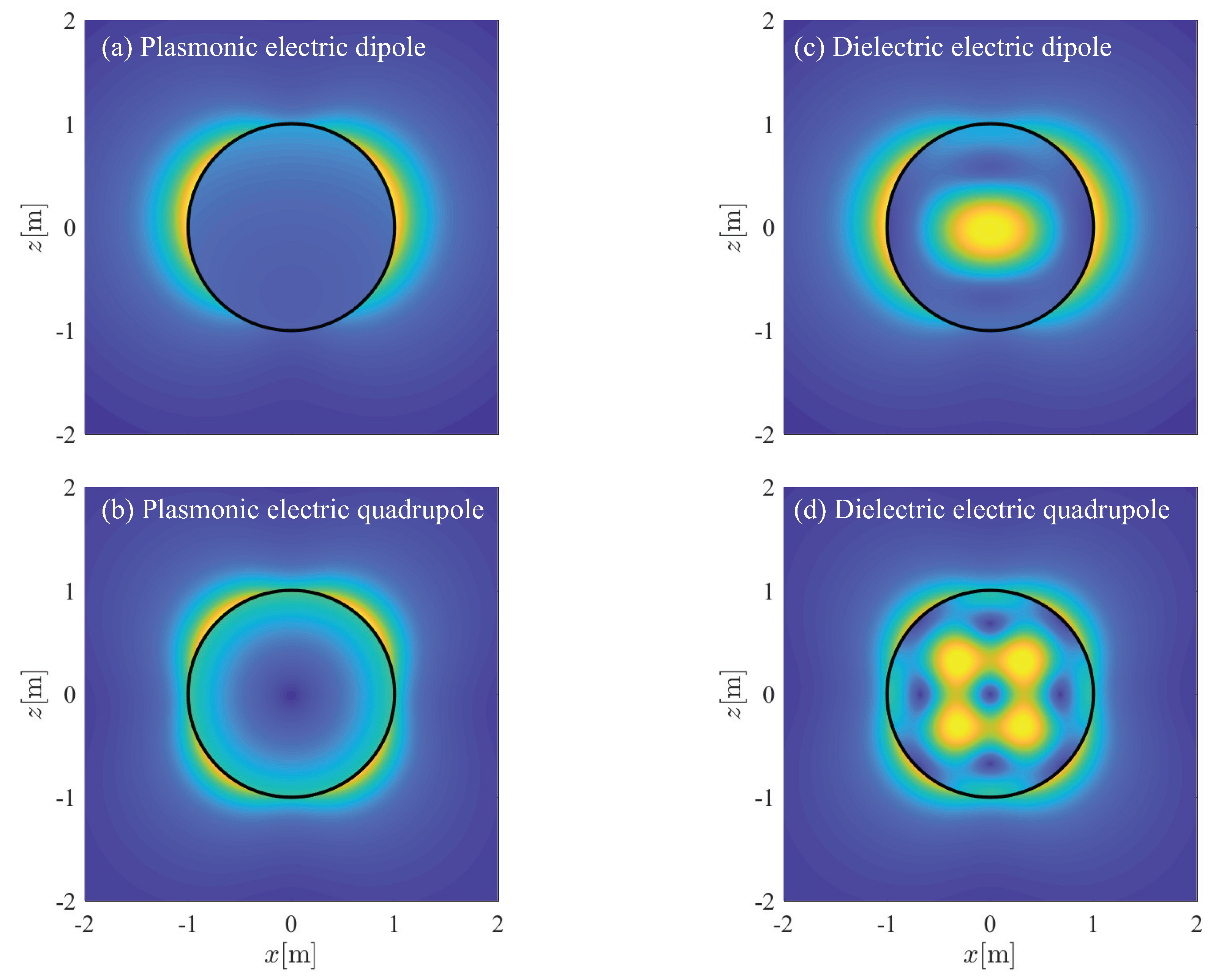
Therefore an obvious question appears: do the electric multipole resonances exhibit any significant differences on their field distributions? One way to approach this question is by exposing the electric field distribution near and inside the sphere. In particular, the amplitude of the scattered field for the first two plasmonic (Figure 7a,b and dielectric Figure 7c,d) electric dipole and quadrupole resonances for a relatively large sphere ( x = 0.75 ) as can be seen in Figure 7. One observes that although the external (scattered) field is identical, the inner field distributions reveals difference in the origin of these resonances. The main differences lie in the fact that the plasmonic resonances exhibit a rather uniform internal field distribution, while their dielectric counterparts exhibit a spatial variation; dielectric resonances are effectively large, especially in the inner domain, due to the high permittivity contrast, while the same does not hold for the plasmonic case.

6. Directional Scattering Characteristics: Forward and Backscattering Conditions

The above discussion allows us to extract information about the behavior of the Mie coefficients. To study the directive nature of the scattering process one should realize that the Mie coefficients represent the amplitudes of the secondary (scattered) fields produced by the sphere under a plane wave illumination. This scattered field is decomposed in a set of spherical multipole harmonics, each of whom contributing to the overall scattering process [16,19]. Different amplitudes result in different multipole contributions, thus leading to variations in the scattering patterns. Understanding these scattering characteristics can lead to the actual control of the scattered radiation; this is a classical but still interesting research challenge for the control of electromagnetic radiation by a single scatterer [31,98,99,100,101], especially in the realm of modern nanotechnology. The following material was partially presented in [102] and is reproduced here with permission, IEEE, 2018.

6.1. The Asymmetry Factor

An available figure of merit that quantifies the directivity of scattering process is the asymmetry factor. The asymmetry factor is the ratio of the weighted scattering cross section over the total scattering cross section [19] and can be calculated in terms of the electric and magnetic coefficients, a n and b n , as
g = Q sca < cos θ > = 4 x 2 n n ( n + 2 ) n + 1 a n a n + 1 + b n b n + 1 + n 2 n + 1 n ( n + 1 ) a n b n
where the Bohren–Huffman notation is used for the averaged cosine [19].
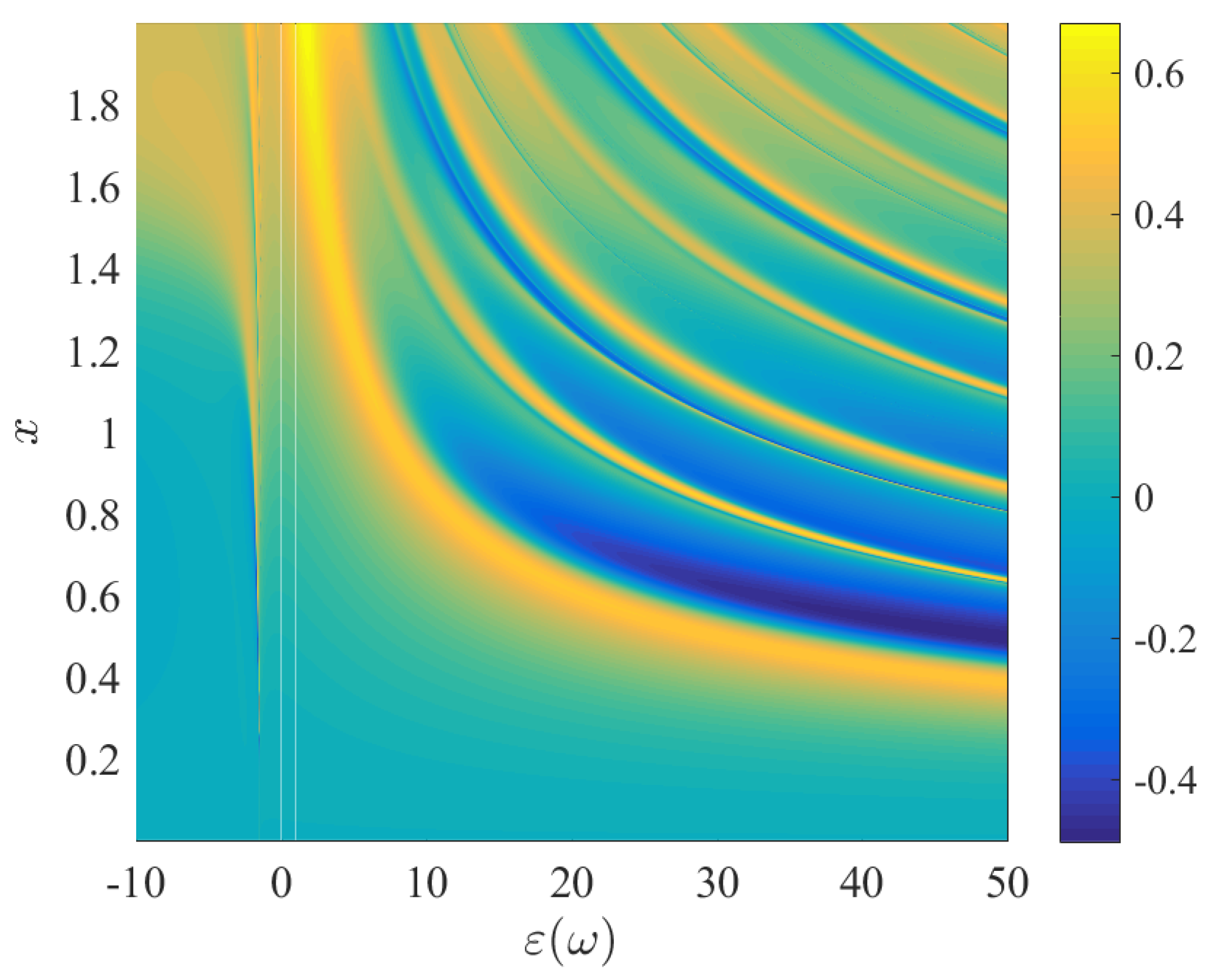
Physically, this figure quantifies the direction of the scatterer power. For example, for values close to g / Q sca = 1 , all the energy is forward directed/scatterer, while g / Q sca = 1 is the backscattering case. The g = 0 case denotes a balance between the forward and backward direction, hence a dipole-like radiation. Actually, for the last case, the scatterer possesses a “symmetric” radiation pattern, i.e., the dipole pattern [19]. In Figure 8, we can see the normalized asymmetry factor g / Q sca is as a function of sphere’s permittivity (assuming no losses) and the size parameter. As we can see, a very vibrant pattern reveals the existence of peaks and valleys of forward and backscattering in the whole spectrum.
Let us now analyze the behavior of the asymmetry factor as can be seen in Equation (28). The multipole coefficients can be written in phasor notation, i.e., a n = a n e j φ n and b n = b n e j ψ n , respectively. First, we assume the case of a very small plasmonic scatterer, where the magnetic multipole terms are b n 0 . It is obvious that the only the electric mulipole terms survive and the asymmetry factor becomes
g = 4 x 2 n n ( n + 2 ) n + 1 a n a n + 1 cos ( φ n φ n + 1 )
having the following special cases : (a) maximum forward scattering if φ n φ n + 1 = 2 k π , k = 0 , 1 , , (b) maximum backward scattering if φ n φ n + 1 = ( 2 k + 1 ) π , k = 0 , 1 , , and (c) dipole-like scattering if φ n φ n + 1 = l π 2 , l = 1 , 2 , . The same results hold also for the case of a magnetic sphere where a n 0 . Alternatively, a forward or backscattering pattern can happen by the constructive (destructive) interference of two consecutive (or any linear combination) of multipole resonances.
However, the second sum of Equation (28) reveals that the asymmetry factor can be also controlled by the interaction of between both electric and magnetic multipole terms. For example, assume the case where only an electric and a magnetic dipole are enabled. In this case, the asymmetry factor reads
g = 6 x 2 a 1 b 1 cos ( φ 1 ψ 1 )
leading to a rather important result, first presented in [103]. We summarize the following three cases where: (a) maximum forward scattering if φ 1 ψ 1 = 2 k π , k = 0 , 1 , , (b) maximum backward scattering φ 1 ψ 1 = ( 2 k + 1 ) π , k = 0 , 1 , , and (c) dipole-like scattering if φ 1 ψ 1 = l π 2 , l = 1 , 2 , .
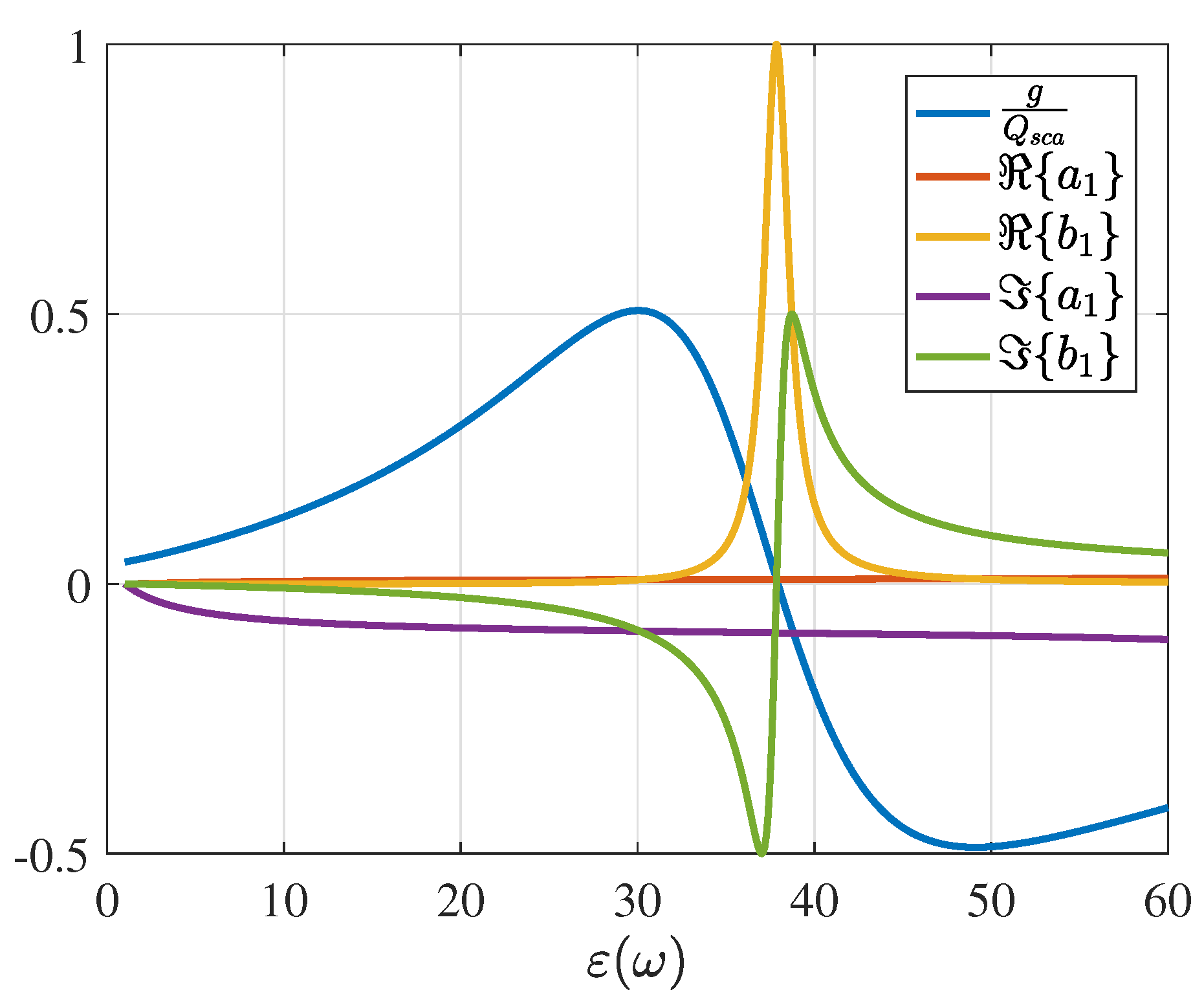
For instance, the asymmetry factor of a small sphere ( x = 0.5 ) is illustrated in Figure 9, where the real and imaginary values of the complex a 1 and b 1 terms are also plotted. It is clear that a maximum forward scattering occurs for the case where the imaginary terms are equal implying a zero phase difference between the coefficients. Similarly, the maximum backscattering happens at the position where the imaginary parts are equal but with different signs. Interestingly, the lineshape of the b 1 coefficient exhibits a Lorentzian-like distribution, as seen in Figure 9. The asymmetry factor exhibits a Fano-like pattern, occurring by the interference of a 1 and b 1 distributions [21].

6.2. Directive Scattering Conditions for Dielectric Resonances

The asymmetry factor gives a complete picture about the underlying physics for the directional scattering characteristics. Since a n and b n are complex-valued in general, it is important to explore for which values of a n and b n the described scattering conditions might hold. A more practical form of the above conditions can be extracted if we re-write the forward and backward scattering efficiencies in the following manner [18,21],
Q B = 1 x 2 n 2 n + 1 1 n a n b n 2
and
Q F = 1 x 2 n 2 n + 1 a n + b n 2
A close observation of the above equations reveals that Q B and Q F can be minimized for certain a n and b n combinations. For the case of the first dipole terms, i.e., a 1 and b 1 , the following conditions can be satisfied
K F = a 1 b 1 = 0 , for maximum forward scattering
and
K B = a 1 + b 1 = 0 , for maximum backward scattering
commonly recognized as the first and second Kerker conditions [103]. However, these are not the only available conditions, e.g., a minimum backscattering can be also obtained when 3 a 1 5 a 2 = 0 . Here, we will concentrate only on the case where the first electric and magnetic dipole interfere accordingly, producing maximum forward or backward scattering for an dielectric sphere. To do so we need to utilize the aforementioned Padé–Mie heuristic method and apply it to both conditions K F and K B .
Indeed, after some calculations (that are here omitted), the Kerker conditions are satisfied for
ε F 2.7437 x 2
and
ε B 8.766 + 3.7263 x 2
These expressions were extracted using a [ 5 / 25 ] Padé expansion of Equations (33) and (34), respectively.
As an illustrative example, we evaluated the required permittivities for maximum forward and backscattering of an x = 0.5 dielectric (lossless) sphere. In this case, Equations (35) and (36) predict resonant maxima at ε F = 30.11 and ε B = 46.78 , respectively. A comparison with the the actual values, i.e., ε F Mie = 30.06 and ε B Mie = 49.02 (see Figure 9), gives a relative error of 0.2 % and 4.5 % , respectively. An easy mnemonic rule can be found for the Equation (35) since Euler number is e 2.718281 . Therefore , Equation (35) recasts to the simpler approximative form
ε F e x 2
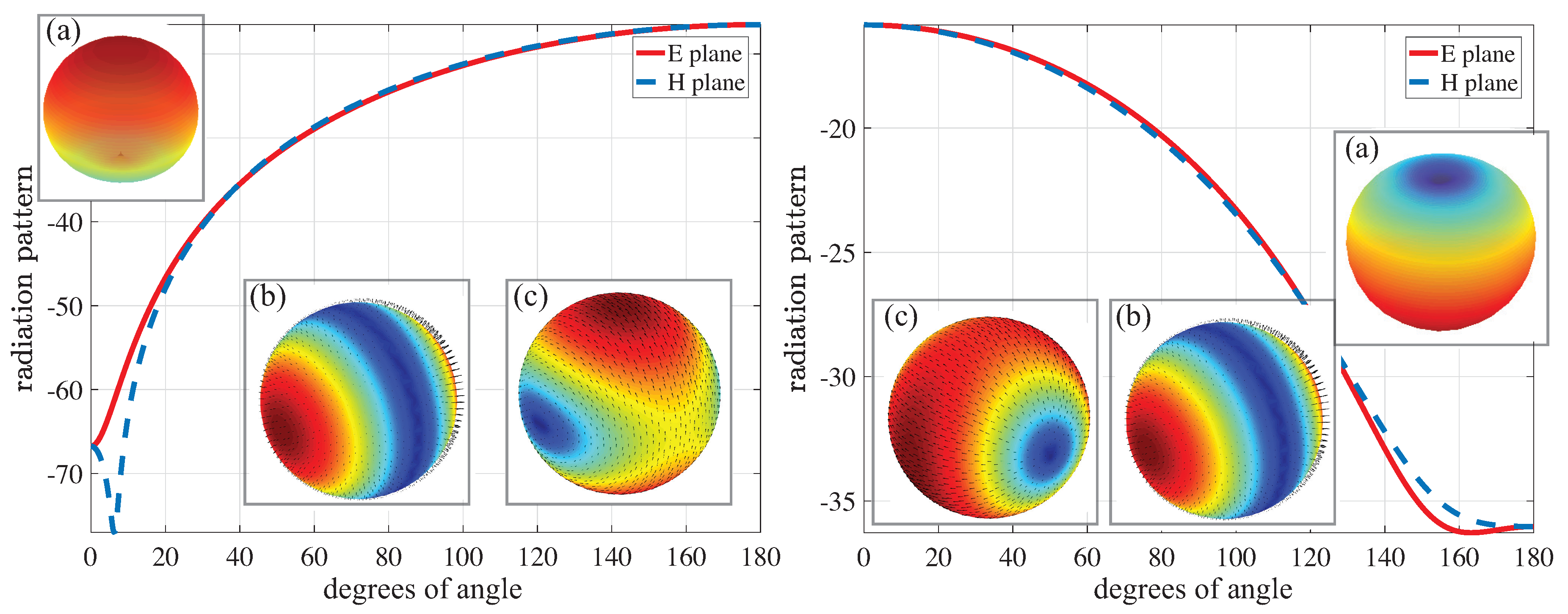
Finally, we present the radiation patterns and surface field distributions for both cases, as illustrated in Figure 10. The surface distribution agrees perfectly with the physical picture; the forward scattering pattern is created by two, spatially aligned dipoles, and the maximum scattering is a result of two perpendicular ones.
At this point, a couple of general conclusions can be drawn. First, Equations (35) and (36) exhibit an inverse-square dependence with respect to the size parameter. This is can be intuitively explained since a similar dependence has been found either for the magnetic multipoles (Table 1) or for the electric multipole terms. For a given material dispersion, e.g., Drude-like materials, the obtained conditions can be used for predicting the optimum size for desired directive scattering. This fact can lead to inverse material engineering philosophies, where the material dispersion will be adjusted following the presented forward and backscattering conditions.
Alternatively, Equations (35) and (36) provide a very simple and intuitive rule for the design of direction selective scattering sources, recently denoted as Huygens sources [4,100,104,105,106,107,108,109]. A potential generalization of the above formulas can be done if we assume an arbitrary-shaped dielectric scatterer, exhibiting its first electric and magnetic resonances. The scattered field can be decomposed in a set of spherical multipole harmonics [49], and hence the above formulas could be used for a first, rough estimation of the positions of the forward and backscattering maxima.

7. Summary

In this article, we have reviewed some of the main characteristics of the resonant behavior of a small sphere. The results are extracted based to the analysis of the Mie coefficients, representing the amplitude of the scattered fields. Three different types of resonances discussed, i.e., the plasmonic electric, dielectric magnetic, and dielectric electric multipole resonances. A connection with the corresponding electrostatic problem (Rayleigh) was described, where the identification of the plasmonic resonances is possible, as a function of the permittivity.
The same electrostatic picture emerges through the Taylor expansion of the Mie coefficients. The usage of a recently introduced heuristic Padé–Mie method for the analysis of the resonant characteristics of small spheres was given. The main focus were dielectric spheres for which both electric and magnetic dipole resonances occur. This Mie–Padé method allows us to draw a unified picture for both plasmonic (electrostatic) and dielectric resonances and their resonant conditions Additionally, the same heuristic method has been used for the generalization of the Kerker conditions for the case of a dielectric sphere, and a set of new maximum scattering conditions were obtained.

Acknowledgments

The authors would like to thank Pasi Ylä-Oijala and Seppo Järvenpää for their support on the visualization of the results. D.T. would like to acknowledge financial support from the ELEC Doctoral School Scholarship and the Nokia Foundation.

Author Contributions

D.T. and A.S conceived the idea of analysing the resonant aspects of the Mie coefficients. D.T. performed the numerical analysis and wrote the manuscript. A.S. supervised the whole study. Both authors edited the manuscript.

Conflicts of Interest

The authors declare no conflict of interest.

Appendix A. Simple Padé Expansions of Spherical Bessel, Hankel, and Riccati–Bessel/Hankel Functions

In this section we give the simple Padé expansions of some necessary functions, such as the spherical Bessel functions and their derivatives. The terms found in Table A1 can be readily used for a simple estimation of the a 1 and b 1 coefficients.
Alternative series expansions for the same functions can be found in classical text-books (for example in ([16] Ch.7.4) and ([49] (Ch.9)). In these expansion at least one pole and one zero is visible. In addition, similar expressions were given by Wiscombe [60] as a computationally efficient way of evaluating the Mie coefficients for small size parameters. Note that the spherical Bessel and Riccati–Bessel functions are purely real for the approximated terms, while Hankel and Riccati–Hankel are complex functions. A physical interpretation can be given to the above expressions, since spherical Bessel functions are real and resemble a standing wave behavior, while Hankel functions are generally complex, representing traveling waves [16].
Table A1. Padé approximants of j n ( x ) and h n ( 1 ) ( x ) and their derivatives.
j 1 ( x ) x 3 1 + 1 10 x 2 h 1 ( 1 ) ( x ) i 2 3 x i 1 2 x 2 x 2 i 2 3 x 3 j 2 ( x ) x 2 15 1 + 1 14 x 2 h 2 ( 1 ) ( x ) 3 i i x 2 2 x 3
x j 1 ( x ) 2 x 3 1 + 1 5 x 2 x h 1 ( 1 ) ( x ) i + 4 3 x i x 2 2 x 2 x 2 i 4 3 x 3 x j 2 ( x ) x 2 5 1 + 5 42 x 2 x h 2 ( 1 ) ( x ) i 6 x 3

References

  1. Prodan, E.; Radloff, C.; Halas, N.J.; Nordlander, P. A hybridization model for the plasmon response of complex nanostructures. Science 2003, 302, 419–422. [Google Scholar] [CrossRef] [PubMed]
  2. Atwater, H.A.; Polman, A. Plasmonics for improved photovoltaic devices. Nat. Mater. 2010, 9, 205–213. [Google Scholar] [CrossRef] [PubMed]
  3. Fan, X.; Zheng, W.; Singh, D.J. Light scattering and surface plasmons on small spherical particles. Light Sci. Appl. 2014, 3, e179. [Google Scholar] [CrossRef]
  4. Kuznetsov, A.I.; Miroshnichenko, A.E.; Brongersma, M.L.; Kivshar, Y.S.; Luk’yanchuk, B. Optically resonant dielectric nanostructures. Science 2016, 354. [Google Scholar] [CrossRef] [PubMed]
  5. Liberal, I.; Engheta, N. Near-zero refractive index photonics. Nat. Photonics 2017, 11, 149–158. [Google Scholar] [CrossRef]
  6. Kelly, K.L.; Coronado, E.; Zhao, L.L.; Schatz, G.C. The optical properties of metal nanoparticles: The influence of size, shape, and dielectric environment. J. Phys. Chem. B 2003, 107, 668–677. [Google Scholar] [CrossRef]
  7. Halas, N.J.; Lal, S.; Chang, W.S.; Link, S.; Nordlander, P. Plasmons in strongly coupled metallic nanostructures. Chem. Rev. 2011, 111, 3913–3961. [Google Scholar] [CrossRef] [PubMed]
  8. Jahani, S.; Jacob, Z. All-dielectric metamaterials. Nat. Nanotechnol. 2016, 11, 23–36. [Google Scholar] [CrossRef] [PubMed]
  9. Shore, R.A. Scattering of an electromagnetic linearly polarized plane wave by a multilayered sphere: Obtaining a computational form of Mie coefficients for the scattered field. IEEE Antennas Propag. Mag. 2015, 57, 69–116. [Google Scholar] [CrossRef]
  10. Arslanagic, S.; Ziolkowski, R.W. Cylindrical and Spherical Active Coated Nanoparticles as Nanoantennas: Active Nanoparticles as Nanoantennas. IEEE Antennas Propag. Mag. 2017, 59, 14–29. [Google Scholar] [CrossRef]
  11. Ammari, H.; Millien, P.; Ruiz, M.; Zhang, H. Mathematical analysis of plasmonic nanoparticles: The scalar case. Arch. Ration. Mech. Anal. 2017, 224, 597–658. [Google Scholar]
  12. Born, M.; Wolf, E. Principles of Optics, 7th ed.; Cambridge University Press: Cambridge, UK, 2010. [Google Scholar]
  13. Bohren, C.F. How can a particle absorb more than the light incident on it? Am. J. Phys. 1983, 51, 323–327. [Google Scholar] [CrossRef]
  14. Myroshnychenko, V.; Rodríguez-Fernández, J.; Pastoriza-Santos, I.; Funston, A.M.; Novo, C.; Mulvaney, P.; Liz-Marzán, L.M.; de Abajo, F.J.G. Modelling the optical response of gold nanoparticles. Chem. Soc. Rev. 2008, 37, 1792–1805. [Google Scholar] [CrossRef] [PubMed]
  15. Mishchenko, M.I.; Travis, L.D.; Lacis, A.A. Scattering, Absorption, and Emission of Light by Small Particles; Cambridge University Press: Cambridge, UK, 2002. [Google Scholar]
  16. Stratton, J.A. Electromagnetic Theory; John Wiley & Sons: Hoboken, NJ, USA, 2007. [Google Scholar]
  17. Hulst, H.C.; Van De Hulst, H. Light Scattering by Small Particles; Courier Corporation: North Chelmsford, MA, USA, 1957. [Google Scholar]
  18. Kerker, M. The Scattering of Light and Other Electromagnetic Radiation: Physical Chemistry: A Series of Monographs; Academic Press: Cambridge, MA, USA, 2013; Volume 16. [Google Scholar]
  19. Bohren, C.F.; Huffman, D.R. Absorption and Scattering of Light by Small Particles; John Wiley & Sons: Hoboken, NJ, USA, 2007. [Google Scholar]
  20. Tribelsky, M.I.; Luk’yanchuk, B.S. Anomalous light scattering by small particles. Phys. Rev. Lett. 2006, 97, 263902. [Google Scholar] [CrossRef] [PubMed]
  21. Luk’yanchuk, B.; Zheludev, N.I.; Maier, S.A.; Halas, N.J.; Nordlander, P.; Giessen, H.; Chong, C.T. The Fano resonance in plasmonic nanostructures and metamaterials. Nat. Mater. 2010, 9, 707–715. [Google Scholar] [CrossRef] [PubMed]
  22. Miroshnichenko, A.E.; Evlyukhin, A.B.; Yu, Y.F.; Bakker, R.M.; Chipouline, A.; Kuznetsov, A.I.; Luk’yanchuk, B.; Chichkov, B.N.; Kivshar, Y.S.; Luk’yanchuk, B.; et al. Nonradiating anapole modes in dielectric nanoparticles. Nat. Commun. 2015, 6, 8069. [Google Scholar] [CrossRef] [PubMed]
  23. Stout, B.; Ross, M. Egocentric physics: Just about Mie. Europhys. Lett. 2017, 119, 44002. [Google Scholar] [CrossRef]
  24. Sihvola, A. Metamaterials in electromagnetics. Metamaterials 2007, 1, 2–11. [Google Scholar] [CrossRef]
  25. Glybovski, S.B.; Tretyakov, S.A.; Belov, P.A.; Kivshar, Y.S.; Simovski, C.R. Metasurfaces: From microwaves to visible. Phys. Rep. 2016, 634, 1–72. [Google Scholar] [CrossRef]
  26. Staude, I.; Schilling, J. Metamaterial-inspired silicon nanophotonics. Nat. Photonics 2017, 11, 274–284. [Google Scholar] [CrossRef]
  27. Maier, S.A.; Atwater, H.A. Plasmonics: Localization and guiding of electromagnetic energy in metal/dielectric structures. J. Appl. Phys. 2005, 98, 011101. [Google Scholar] [CrossRef]
  28. Schuller, J.A.; Zia, R.; Taubner, T.; Brongersma, M.L. Dielectric metamaterials based on electric and magnetic resonances of silicon carbide particles. Phys. Rev. Lett. 2007, 99, 107401. [Google Scholar] [CrossRef] [PubMed]
  29. Polman, A. Plasmonics Applied. Science 2008, 322, 868–869. [Google Scholar] [CrossRef] [PubMed]
  30. Evlyukhin, A.B.; Novikov, S.M.; Zywietz, U.; Eriksen, R.L.; Reinhardt, C.; Bozhevolnyi, S.I.; Chichkov, B.N. Demonstration of magnetic dipole resonances of dielectric nanospheres in the visible region. Nano Lett. 2012, 12, 3749–3755. [Google Scholar] [CrossRef] [PubMed]
  31. Krasnok, A.E.; Simovski, C.R.; Belov, P.A.; Kivshar, Y.S. Superdirective dielectric nanoantennas. Nanoscale 2014, 6, 7354–7361. [Google Scholar] [CrossRef] [PubMed]
  32. Monticone, F.; Alù, A. The quest for optical magnetism: from split-ring resonators to plasmonic nanoparticles and nanoclusters. J. Mater. Chem. C 2014, 2, 9059–9072. [Google Scholar] [CrossRef]
  33. Kruk, S.; Kivshar, Y. Functional meta-optics and nanophotonics Governed by Mie resonances. ACS Photonics 2017, 4, 2638–2649. [Google Scholar]
  34. Stewart, M.E.; Anderton, C.R.; Thompson, L.B.; Maria, J.; Gray, S.K.; Rogers, J.A.; Nuzzo, R.G. Nanostructured plasmonic sensors. Chem. Rev. 2008, 108, 494–521. [Google Scholar]
  35. Alù, A.; Engheta, N. Cloaking a sensor. Phys. Rev. Lett. 2009, 102, 233901. [Google Scholar] [CrossRef] [PubMed]
  36. Kerker, M. Invisible bodies. J. Opt. Soc. Am. 1975, 65, 376–379. [Google Scholar] [CrossRef]
  37. Alù, A.; Engheta, N. Achieving transparency with plasmonic and metamaterial coatings. Phys. Rev. E 2005, 72, 016623. [Google Scholar] [CrossRef] [PubMed]
  38. Pendry, J.B.; Schurig, D.; Smith, D.R. Controlling Electromagnetic Fields. Science 2006, 312, 1780–1782. [Google Scholar] [CrossRef] [PubMed]
  39. Argyropoulos, C.; Chen, P.Y.; Monticone, F.; D’Aguanno, G.; Alù, A. Nonlinear Plasmonic Cloaks to Realize Giant All-Optical Scattering Switching. Phys. Rev. Lett. 2012, 108, 263905. [Google Scholar] [CrossRef] [PubMed]
  40. Monticone, F.; Alù, A. Invisibility exposed: Physical bounds on passive cloaking. Optica 2016, 3, 718–724. [Google Scholar] [CrossRef]
  41. Ruan, Z.; Fan, S. Superscattering of light from subwavelength nanostructures. Phys. Rev. Lett. 2010, 105, 013901. [Google Scholar] [CrossRef] [PubMed]
  42. Gao, D.; Novitsky, A.; Zhang, T.; Cheong, F.C.; Gao, L.; Lim, C.T.; Luk’yanchuk, B.; Qiu, C.W. Unveiling the correlation between non-diffracting tractor beam and its singularity in Poynting vector. Laser Photonics Rev. 2015, 9, 75–82. [Google Scholar] [CrossRef]
  43. Lannebère, S.; Silveirinha, M.G. Optical meta-atom for localization of light with quantized energy. Nat. Commun. 2015, 6, 8766. [Google Scholar] [CrossRef] [PubMed]
  44. Ra’di, Y.; Asadchy, V.S.; Kosulnikov, S.U.; Omelyanovich, M.M.; Morits, D.; Osipov, A.V.; Simovski, C.R.; Tretyakov, S.A. Full Light Absorption in Single Arrays of Spherical Nanoparticles. ACS Photonics 2015, 2, 653–660. [Google Scholar] [CrossRef]
  45. Strutt, J.W. (Baron of Rayleigh) On the scattering of light by small particles. Philos. Mag. 1871, 41, 447–454. [Google Scholar]
  46. Sipe, J.E.; Kranendonk, J.V. Macroscopic electromagnetic theory of resonant dielectrics. Phys. Rev. A 1974, 9, 1806–1822. [Google Scholar] [CrossRef]
  47. Ruppin, R. Plasmon frequencies of small metal spheres. J. Phys. Chem. Solids 1978, 39, 233–237. [Google Scholar] [CrossRef]
  48. Ruppin, R. Optical properties of small metal spheres. Phys. Rev. B 1975, 11, 2871–2876. [Google Scholar] [CrossRef]
  49. Jackson, J.D. Classical Electrodynamics, 3rd ed.; John Wiley & Sons: Hoboken, NJ, USA, 1999. [Google Scholar]
  50. Maier, S.A. Plasmonics: Fundamentals and Applications; Springer Science & Business Media: Berlin, Germany, 2007. [Google Scholar]
  51. Kreibig, U.; Vollmer, M. Optical Properties of Metal Clusters; Springer: Berlin, Germany, 1995. [Google Scholar]
  52. Khurgin, J.B. How to deal with the loss in plasmonics and metamaterials. Nat. Nanotechnol. 2015, 10, 2–6. [Google Scholar] [CrossRef] [PubMed]
  53. Johnson, B.R. Theory of morphology-dependent resonances: shape resonances and width formulas. J. Opt. Soc. Am. A 1993, 10, 343–352. [Google Scholar] [CrossRef]
  54. Aden, A.L.; Kerker, M. Scattering of electromagnetic waves from two concentric spheres. J. Appl. Phys. 1951, 22, 1242–1246. [Google Scholar] [CrossRef]
  55. Wait, J.R. Electromagnetic scattering from a radially inhomogeneous sphere. Appl. Sci. Res. Sect. B 1962, 10, 441–450. [Google Scholar] [CrossRef]
  56. Tai, C.T. The electromagnetic theory of the spherical luneberg lens. Appl. Sci. Res. Sect. B 1959, 7, 113–130. [Google Scholar] [CrossRef]
  57. Wyatt, P.J. Scattering of electromagnetic plane waves from inhomogeneous spherically symmetric objects. Phys. Rev. 1962, 127, 1837–1843. [Google Scholar] [CrossRef]
  58. Qiu, C.W.; Li, L.W.; Yeo, T.S.; Zouhdi, S. Scattering by rotationally symmetric anisotropic spheres: Potential formulation and parametric studies. Phys. Rev. E 2007, 75, 026609. [Google Scholar] [CrossRef] [PubMed]
  59. Wallén, H.; Kettunen, H.; Sihvola, A. Anomalous absorption, plasmonic resonances, and invisibility of radially anisotropic spheres. Radio Sci. 2015, 50, 18–28. [Google Scholar] [CrossRef]
  60. Wiscombe, W.J. Improved Mie scattering algorithms. Appl. Opt. 1980, 19, 1505–1509. [Google Scholar] [CrossRef] [PubMed]
  61. García-Etxarri, A.; Gómez-Medina, R.; Froufe-Pérez, L.S.; López, C.; Chantada, L.; Scheffold, F.; Aizpurua, J.; Nieto-Vesperinas, M.; Sáenz, J.J. Strong magnetic response of submicron Silicon particles in the infrared. Opt. Express 2011, 19, 4815–4826. [Google Scholar] [CrossRef] [PubMed] [Green Version]
  62. Kuznetsov, A.I.; Miroshnichenko, A.E.; Fu, Y.H.; Zhang, J.; Luk’yanchuk, B. Magnetic light. Sci. Rep. 2012, 2, 492. [Google Scholar] [CrossRef] [PubMed]
  63. Tzarouchis, D.C.; Ylä-Oijala, P.; Sihvola, A. Resonant scattering characteristics of homogeneous dielectric sphere. IEEE Trans. Antennas Propag. 2017, 65, 3184–3191. [Google Scholar] [CrossRef]
  64. Sihvola, A.H. Electromagnetic Mixing Formulas and Applications; Number 47; IET: London, UK, 1999. [Google Scholar]
  65. Sihvola, A.H. Character of surface plasmons in layered spherical structures. Prog. Electromagn. Res. 2006, 62, 317–331. [Google Scholar] [CrossRef]
  66. Averitt, R.D.; Westcott, S.L.; Halas, N.J. Linear optical properties of gold nanoshells. J. Opt. Soc. Am. B 1999, 16, 1824–1832. [Google Scholar] [CrossRef]
  67. Hao, F.; Nordlander, P. Efficient dielectric function for FDTD simulation of the optical properties of silver and gold nanoparticles. Chem. Phys. Lett. 2007, 446, 115–118. [Google Scholar] [CrossRef]
  68. Mayergoyz, I.D.; Fredkin, D.R.; Zhang, Z. Electrostatic (plasmon) resonances in nanoparticles. Phys. Rev. B 2005, 72, 155412. [Google Scholar] [CrossRef]
  69. Wang, F.; Shen, Y.R. General properties of local plasmons in metal nanostructures. Phys. Rev. Lett. 2006, 97, 206806. [Google Scholar] [CrossRef] [PubMed]
  70. Sihvola, A.; Lindell, I.V. Transmission Line Analogy for Calculating the Effective Permittivity of Mixtures with Spherical Multilayer Scatterers. J. Electromagn. Waves Appl. 1988, 2, 741–756. [Google Scholar]
  71. Alù, A.; Engheta, N. Polarizabilities and effective parameters for collections of spherical nanoparticles formed by pairs of concentric double-negative, single-negative, and/or double-positive metamaterial layers. J. Appl. Phys. 2005, 97, 094310. [Google Scholar] [CrossRef]
  72. Tzarouchis, D.C.; Sihvola, A. General scattering characteristics of resonant core–shell spheres. IEEE Trans. Antennas Propag. 2018, 66, 323–330. [Google Scholar] [CrossRef]
  73. Mukhopadhyay, G.; Lundqvist, S. Density oscillations and density response in systems with nonuniform electron density. Nuovo Cimento B 1975, 27, 1–18. [Google Scholar] [CrossRef]
  74. Román-Velázquez, C.E.; Noguez, C. Designing the plasmonic response of shell nanoparticles: Spectral representation. J. Chem. Phys. 2011, 134, 044116. [Google Scholar] [CrossRef] [PubMed]
  75. Prodan, E.; Nordlander, P. Exchange and correlations effects in small metallic nanoshells. Chem. Phys. Lett. 2001, 349, 153–160. [Google Scholar] [CrossRef]
  76. Prodan, E.; Nordlander, P. Electronic structure and polarizability of metallic nanoshells. Chem. Phys. Lett. 2002, 352, 140–146. [Google Scholar] [CrossRef]
  77. Chýlek, P. Resonance structure of Mie scattering: distance between resonances. J. Opt. Soc. Am. A 1990, 7, 1609–1613. [Google Scholar] [CrossRef]
  78. Lam, C.C.; Leung, P.T.; Young, K. Explicit asymptotic formulas for the positions, widths, and strengths of resonances in Mie scattering. J. Opt. Soc. Am. B 1992, 9, 1585–1592. [Google Scholar] [CrossRef]
  79. Kuwata, H.; Tamaru, H.; Esumi, K.; Miyano, K. Resonant light scattering from metal nanoparticles: Practical analysis beyond rayleigh approximation. Appl. Phys. Lett. 2003, 83, 4625–4627. [Google Scholar] [CrossRef]
  80. Le Ru, E.C.; Somerville, W.R.C.; Auguié, B. Radiative correction in approximate treatments of electromagnetic scattering by point and body scatterers. Phys. Rev. A 2013, 87, 012504. [Google Scholar] [CrossRef]
  81. Schebarchov, D.; Auguié, B.; Le Ru, E.C. Simple accurate approximations for the optical properties of metallic nanospheres and nanoshells. Phys. Chem. Chem. Phys. 2013, 15, 4233–4242. [Google Scholar] [CrossRef] [PubMed]
  82. Colom, R.; Devilez, A.; Enoch, S.; Stout, B.; Bonod, N. Polarizability expressions for predicting resonances in plasmonic and Mie scatterers. Phys. Rev. A 2017, 95, 63833. [Google Scholar] [CrossRef]
  83. Conwell, P.R.; Barber, P.W.; Rushforth, C.K. Resonant spectra of dielectric spheres. J. Opt. Soc. Am. A 1984, 1, 62–67. [Google Scholar] [CrossRef]
  84. Power, D. Approximate analytic continuation of the Rayleigh series (radar cross-section). IEEE Trans. Antennas Propag. 1988, 36, 1652–1654. [Google Scholar] [CrossRef]
  85. Tzarouchis, D.C.; Ylä-Oijala, P.; Sihvola, A. Unveiling the scattering behavior of small spheres. Phys. Rev. B 2016, 94, 140301. [Google Scholar] [CrossRef]
  86. Baker, G.A.; Graves-Morris, P.R. Padé Approximants; Cambridge University Press: Cambridge, UK, 1996; Volume 59. [Google Scholar]
  87. Bender, C.M.; Orszag, S.A. Advanced Mathematical Methods for Scientists and Engineers I: Asymptotic Methods and Perturbation Theory; Springer Science & Business Media: Berlin, Germany, 2013. [Google Scholar]
  88. Mei, Z.; Sarkar, T.K.; Salazar-Palma, M. A study of negative permittivity and permeability for small sphere. IEEE Antennas Wirel. Propag. Lett. 2013, 12, 1228–1231. [Google Scholar] [CrossRef]
  89. Meier, M.; Wokaun, A. Enhanced fields on large metal particles: Dynamic depolarization. Opt. Lett. 1983, 8, 581–583. [Google Scholar] [CrossRef] [PubMed]
  90. De Vries, P.; van Coevorden, D.V.; Lagendijk, A. Point scatterers for classical waves. Rev. Mod. Phys. 1998, 70, 447–466. [Google Scholar] [CrossRef]
  91. Doyle, W.T. Optical properties of a suspension of metal spheres. Phys. Rev. B 1989, 39, 9852–9858. [Google Scholar] [CrossRef]
  92. Carminati, R.; Greffet, J.J.; Henkel, C.; Vigoureux, J.M. Radiative and non-radiative decay of a single molecule close to a metallic nanoparticle. Opt. Commun. 2006, 261, 368–375. [Google Scholar] [CrossRef]
  93. Moroz, A. Depolarization field of spheroidal particles. J. Opt. Soc. Am. B 2009, 26, 517–527. [Google Scholar] [CrossRef]
  94. Yu, R.; Liz-Marzán, L.M.; García de Abajo, F.J. Universal analytical modeling of plasmonic nanoparticles. Chem. Soc. Rev. 2017, 46, 6710–6724. [Google Scholar] [CrossRef] [PubMed]
  95. Liberal, I.; Ziolkowski, R.W. Analytical and equivalent circuit models to elucidate power balance in scattering problems. IEEE Trans. Antennas Propag. 2013, 61, 2714–2726. [Google Scholar] [CrossRef]
  96. Tretyakov, S. Maximizing absorption and scattering by dipole particles. Plasmonics 2014, 9, 935–944. [Google Scholar] [CrossRef]
  97. Osipov, A.V.; Tretyakov, S.A. Modern Electromagnetic Scattering Theory with Applications; Wiley: Hoboken, NJ, USA, 2017. [Google Scholar]
  98. Geffrin, J.M.; García-Cámara, B.; Gómez-Medina, R.; Albella, P.; Froufe-Pérez, L.S.; Eyraud, C.; Litman, A.; Vaillon, R.; González, F.; Nieto-Vesperinas, M.; et al. Magnetic and electric coherence in forward- and back-scattered electromagnetic waves by a single dielectric subwavelength sphere. Nat. Commun. 2012, 3, 1171. [Google Scholar] [CrossRef] [PubMed]
  99. Person, S.; Jain, M.; Lapin, Z.; Sáenz, J.J.; Wicks, G.; Novotny, L. Demonstration of zero optical backscattering from single nanoparticles. Nano Lett. 2013, 13, 1806–1809. [Google Scholar] [CrossRef] [PubMed]
  100. Luk’yanchuk, B.S.; Voshchinnikov, N.V.; Paniagua-Domínguez, R.; Kuznetsov, A.I. Optimum forward light scattering by spherical and spheroidal dielectric nanoparticles with high refractive index. ACS Photonics 2015, 2, 993–995. [Google Scholar] [CrossRef]
  101. Alaee, R.; Filter, R.; Lehr, D.; Lederer, F.; Rockstuhl, C. A generalized Kerker condition for highly directive nanoantennas. Opt. Lett. 2015, 40, 2645–2648. [Google Scholar] [CrossRef] [PubMed]
  102. Tzarouchis, D.C.; Ylä-Oijala, P.; Sihvola, A. Light scattering characteristics of a small sphere: Resonant and directive scattering conditions. In Proceeding of the 2017 Progress in Electromagnetics Research Symposium, St Petersburg, Russia, 22–25 May 2017; pp. 1503–1510. [Google Scholar]
  103. Kerker, M.; Wang, D.S.; Giles, C.L. Electromagnetic scattering by magnetic spheres. J. Opt. Soc. Am. 1983, 73, 765–767. [Google Scholar] [CrossRef]
  104. Liberal, I.; Ederra, I.; Gonzalo, R.; Ziolkowski, R.W. Induction theorem analysis of resonant nanoparticles: Design of a Huygens source nanoparticle laser. Phys. Rev. Appl. 2014, 1, 044002. [Google Scholar] [CrossRef]
  105. Naraghi, R.R.; Sukhov, S.; Dogariu, A. Directional control of scattering by all-dielectric core-shell spheres. Opt. Lett. 2015, 40, 585–588. [Google Scholar] [CrossRef] [PubMed]
  106. Fu, Y.H.; Kuznetsov, A.I.; Miroshnichenko, A.E.; Yu, Y.F.; Luk’yanchuk, B. Directional visible light scattering by silicon nanoparticles. Nat. Commun. 2013, 4, 1527. [Google Scholar] [CrossRef] [PubMed]
  107. Ziolkowski, R.W. Metamaterial-inspired, electrically small Huygens sources. IEEE Antennas Wirel. Propag. Lett. 2010, 9, 501–505. [Google Scholar]
  108. Ziolkowski, R.W. Using Huygens multipole arrays to realize unidirectional needle-like radiation. Phys. Rev. X 2017, 7, 31017. [Google Scholar] [CrossRef]
  109. Campione, S.; Basilio, L.I.; Warne, L.K.; Sinclair, M.B. Tailoring dielectric resonator geometries for directional scattering and Huygens’ metasurfaces. Opt. Express 2015, 23, 2293. [Google Scholar] [CrossRef] [PubMed]
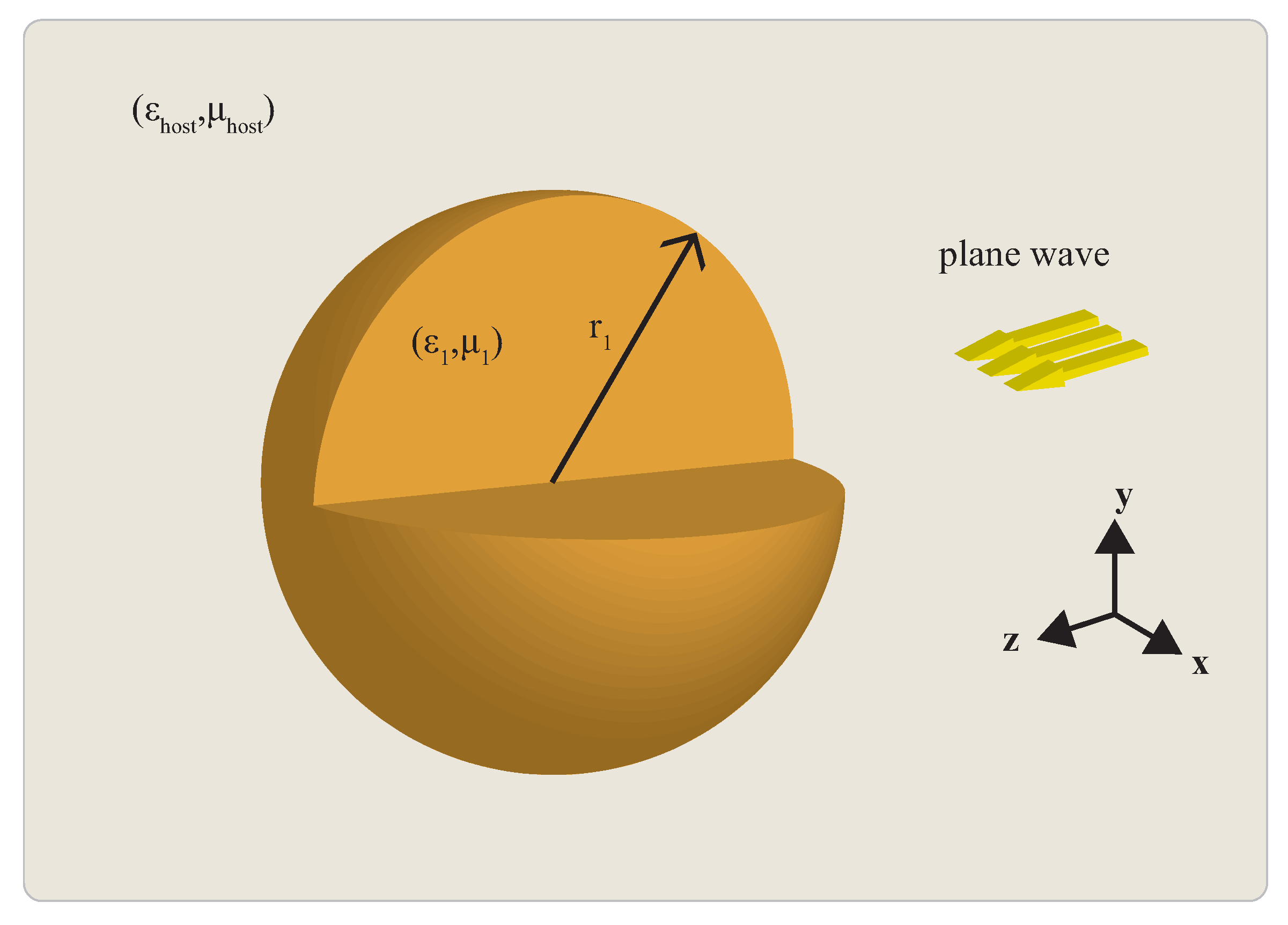
Figure 1. Conceptual visualization of the general problem under consideration: plane wave scattering by a sphere of radius r 1 and material ε 1 , μ 1 in a host medium with general material parameters ε host , μ host . In this review, the host medium is vacuum with ε host = 1 , μ host = 1 and the sphere is magnetically inert, i.e., μ 1 = 1 . The plane wave is z propagated, E x polarized.
Applsci 08 00184 g001
Figure 2. The scattering efficiency of a homogeneous sphere (in logarithmic scale), normalized for better visualization of the results, as a function of the permittivity (lossless case) and the size parameter. The yellow regions correspond to radiation enhancement regions. Note two different regions, one for negative (plasmonic region) and for positive (dielectric) permittivity. The inset figure shows an magnification on the plasmonic region, where the first three electric multipole resonances are visible. (Adapted with permission from [63], IEEE, 2017).
Applsci 08 00184 g002
Figure 3. The total scattering efficiency (blue line), in logarithmic scale, as a function of the permittivity (lossless case) for a fixed size parameter x = 0.75 . Additionally, the lines a 1 , a 2 , and a 3 (dashed colorful lines) depict the absolute value of the first three electric multipoles, while b 1 , b 2 , and b 3 (dash-dot colorful lines) illustrate the magnetic dipole, quadrupole, and octupole terms, respectively. The inset figure (left column) depict the corresponding surface charge distributions for the a 1 , a 2 , and a 3 electric multipoles, while the inset figure (top) the corresponding surface electric current distributions for b 1 , b 2 , and b 3 magnetic multipoles, respectively. Note that the a multipoles resonate at both plasmonic ( ε < 0 ) and dielectric ( ε > 0 ) regions, exhibiting an identical charge distribution. The ampitude of a n and b n coefficients is bounded at the [ 0 , 1 ] interval.
Applsci 08 00184 g003
Figure 4. The total scattering efficiency of a deeply subwavelength sphere ( x = 0.01 ) in the plasmonic region. One main electric dipole resonance is observed at 2 , while a second ultra-sharp resonance at 1.5 . The field distribution for the dipolar resonance is characterized by a dipole-like external field, with a constant field at the inside domain of the sphere. This resonance can be seen in Figure 2 (inset picture).
Applsci 08 00184 g004
Figure 5. Schematic representation of a core–shell sphere subject to a electrostatic field embedded in a host medium. Region 1 represents the shell region, while region 2 represents the core.
Applsci 08 00184 g005
Figure 6. Electric and magnetic field distribution (amplitude) of the symmetric (top) and antisymmetric (bottom) plasmonic resonances of a very small ( x = 0.01 ) core–shell sphere occurring for η = 0.1 (left) and η = 0.9 (right) radius ratio, respectively. The inset figures depict the scattering spectrum (extinction efficiency) for (a) η = 0.1 and (b) for η = 0.9 . The center pictures illustrate the field distribution (electric and magnetic) of the plasmonic resonance for a solid sphere for comparison.
Applsci 08 00184 g006
Figure 7. The amplitude of the scattered electric field distribution for a sphere of x = 0.75 at: (a) ε 1 3.5 ; (b) ε 1 1.754 ; (c) ε 1 32.9 ; and (d) ε 1 57.93 . These resonances correspond to the first two plasmonic and dielectric resonances, i.e., (a,c) dipole and (b,d) quadrupole, respectively.
Applsci 08 00184 g007
Figure 8. The normalized asymmetry factor, g Q sca , as a function of sphere’s permittivity and the size parameter. Note the existence of peaks and valleys, which is a direct indication of the interference of resonant multipoles in the studied spectrum.
Applsci 08 00184 g008
Figure 9. The normalized asymmetry factor for the case of a lossless sphere of size x = 0.5 . The maximum peak (forward scattering) occurs at ε F Mie = 30.06 and the minimum valley (maximum backscattering) at ε B Mie = 49.02 .
Applsci 08 00184 g009
Figure 10. The radiation and surface field patterns of maximum forward scattering (left set of images) and maximum backscattering (right set of images). Left: The central subfigure illustrates the far field radiation pattern (in dB) of the maximum forward scattering for both perpendicular planes, E and H, spanning between 0 degrees (backward scattering direction) to 180 degrees of angle (forward scattering direction). The inset subfigures depict: (a) 3D far-field pattern; (b) the surface electric field; and (c) the tangential magnetic field. Right: Similarly, the backscattering radiation pattern, i.e.,: (a) 3D far-field pattern; (b) the surface electric field; and (c) the tangential magnetic field. Note the differences in direction of the radiation patterns and the differences in the orientation of the magnetic field.
Applsci 08 00184 g010
Table 1. Rules of the resonances on a homogeneous sphere for n = 1 , 2 , 3 , .
ε b n = 2 2 n 1 + c n x 2 i 2 2 n 1 ! ! 2 x 2 n 1
ε a n d = 2 n + c n + 1 x 2 i 2 n 2 n 1 ! ! 2 x 2 n + 1
ε a n p = n + 1 n + 2 ( 2 n + 1 ) ( n + 1 ) n 2 ( 2 n 1 ) ( 2 n + 3 ) x 2 i n + 1 n 2 n 1 ! ! 2 x 2 n + 1
Table 2. Values of uses parameters for the b n and a n pole resonances.
n12345
c n π 4.49345.76346.98798.1428