1. Introduction
For the purposes of rock engineering design, eight modeling methods have been categorized, including pre-existing standard methods, analytical methods, basic and extended numerical methods, precedent type analysis, empirical classification systems, the basic system approach, and the combined system approach [
1]. The empirical classification systems that have been developed for rock mass are the backbone for empirical support design in tunnels, and are currently widely used. These systems have been continuously updated for this particular purpose. In 1946, Terzaghi was the first to develop a rock mass classification system, which was known as rock load factor classification, and a number of systems for rock mass quality determination have been developed since. These systems consider the most essential parameters affecting the rock mass behavior to rate its quality. In designing tunnel supports, the geomechanical classifications, which are also known as the Rock Mass Rating (RMR) system, the tunneling quality index (
Q) system, and the Rock Mass index (
RMi), are currently internationally accepted, and are widely used in the field of tunneling for preliminary support designs [
2]. Originally, these empirical classification systems were developed, refined, and updated for the tunnel support [
3]. However, they also have applications in other engineering projects such as mining [
4,
5,
6,
7], slopes [
8,
9,
10,
11,
12], and tunnel-boring machine (TBM) tunnels [
13,
14]. Comparing the application of these systems for tunneling in high-stress environments, the
Q and
RMi systems are preferred over the RMR, because their parameters are more relevant for the purpose [
15].
The
Q-system classification was developed in 1974 [
16], and major changes in its characterizations and classifications were made in 1993 and 2002 [
17,
18]. In characterization, the foremost changes include the modification of the stress reduction factor (
SRF) and intact rock uniaxial compressive strength (
σc), respectively. The system was initially developed for tunneling cases in hard and jointed rock mass [
19], and thus, this system is more often applied in jointed rock mass [
20]. However, its application in tunnel support design is limited to an equivalent dimension (D
e) ranging from 2.5 to 30, and a
Q value ranging from 0.1 to 40 [
21].
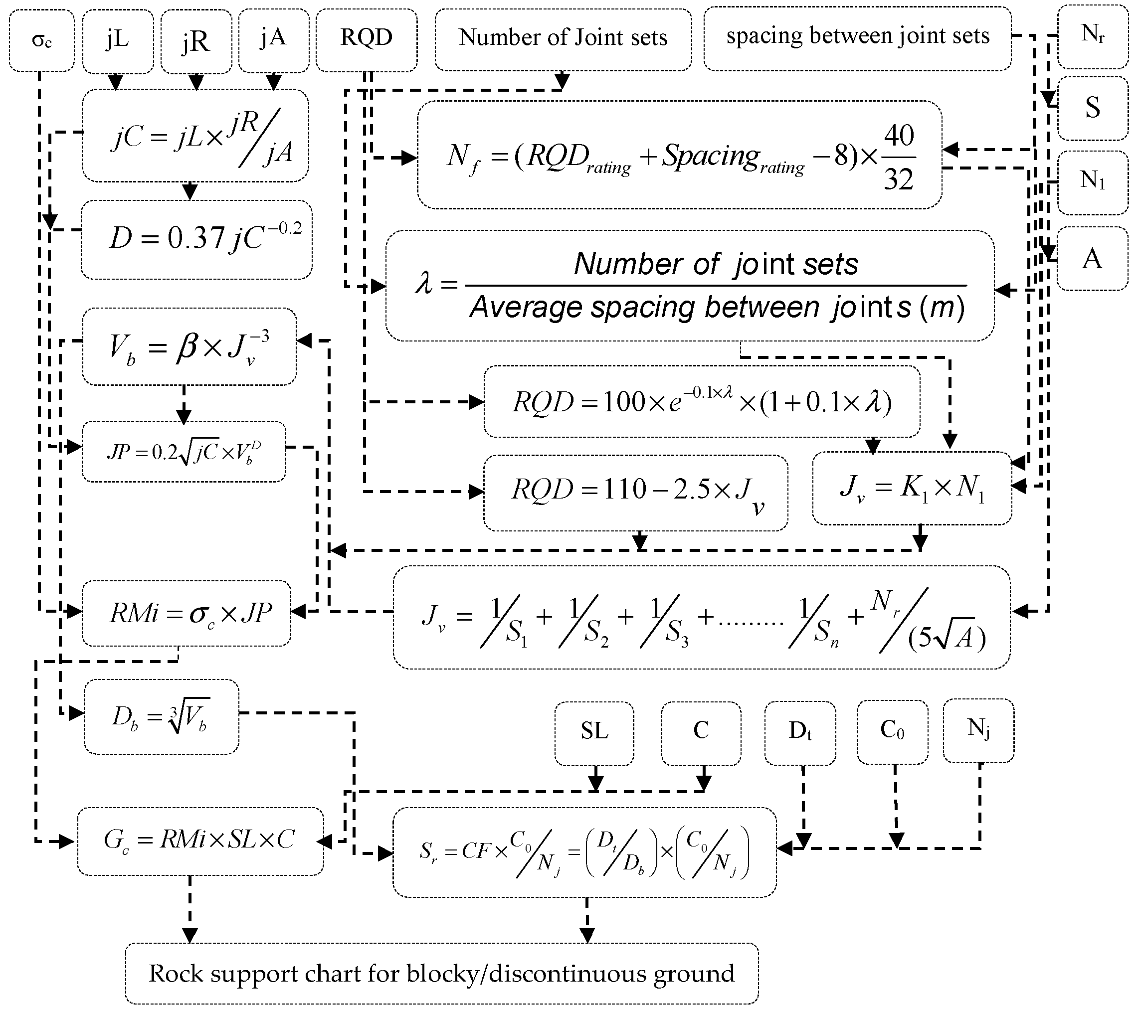
The Rock Mass index (
RMi) system was proposed by Palmström in 1995 primarily for the reduced rock mass strength caused by jointing [
22] and for rock support estimation in tunneling. The system was revised, and major developments and simplifications were made after five years of successful use and experience based on practical applications [
23]. These simplifications are in terms of reduction in the input parameters and correlation between block volume (
Vb) and volumetric joint count (
Jv). This leads to easier and quicker calculations of the tunnel support parameters; i.e., the ground condition factor
Gc and size ratio factor
Sr, especially cases where limited field investigations have been performed.
In tunneling, in situ stresses are the key factors—besides rock mass and project-related features—that control the ground behavior, but empirical classification systems have limitations in application in high stress-environments [
15,
24]. The limitations of empirical classification systems, which are based on the ground behavior for underground excavation in rock engineering, are shown in
Table 1. In comparing the
Q system and
RMi for preliminary tunnel support design in the case of high in-situ stresses, the
Q system has a stress reduction factor (
SRF) for the purpose, but it is limited to massive rock (
Table 2) [
17,
25]. The
RMi system uses stress level (SL) for the first three conditions of
Table 2 for jointed rock mass, and has an inverse relation with
SRF; it can also reveal that a high stress has a positive impact on the ground condition [
22,
23]. In high-stress rock mass environments, the presence of joints has a positive impact on tunneling [
26], and for this reason de-stress blasting is successfully used as a rockburst preventive measure [
27,
28]. Neither system gives guidelines for
SRF and SL in high-stressed jointed rock mass (the last three categories of
Table 2), which is actually a limitation of the data on which these systems are based.
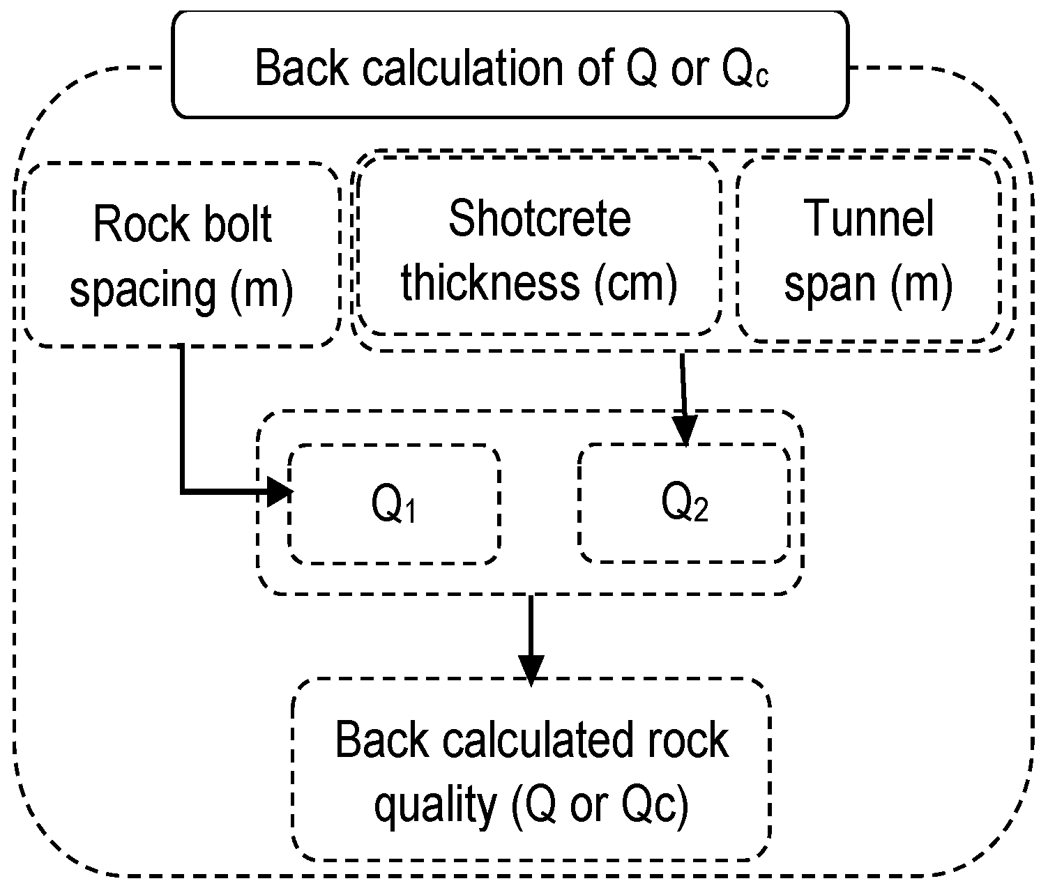
In this study, for the subclasses 4 and 5 of
Table 2, application of the
Q and
RMi systems is extended from already-supported tunnel sections, which are excavated in high-stressed jointed rock mass. Equations and charts are recommended for the determination of
SRF in order to extend the application of the
Q system. An alternate approach of using the
Q-system chart to recommend supports from a modified
RMi system is taken.
4. Numerical Modeling
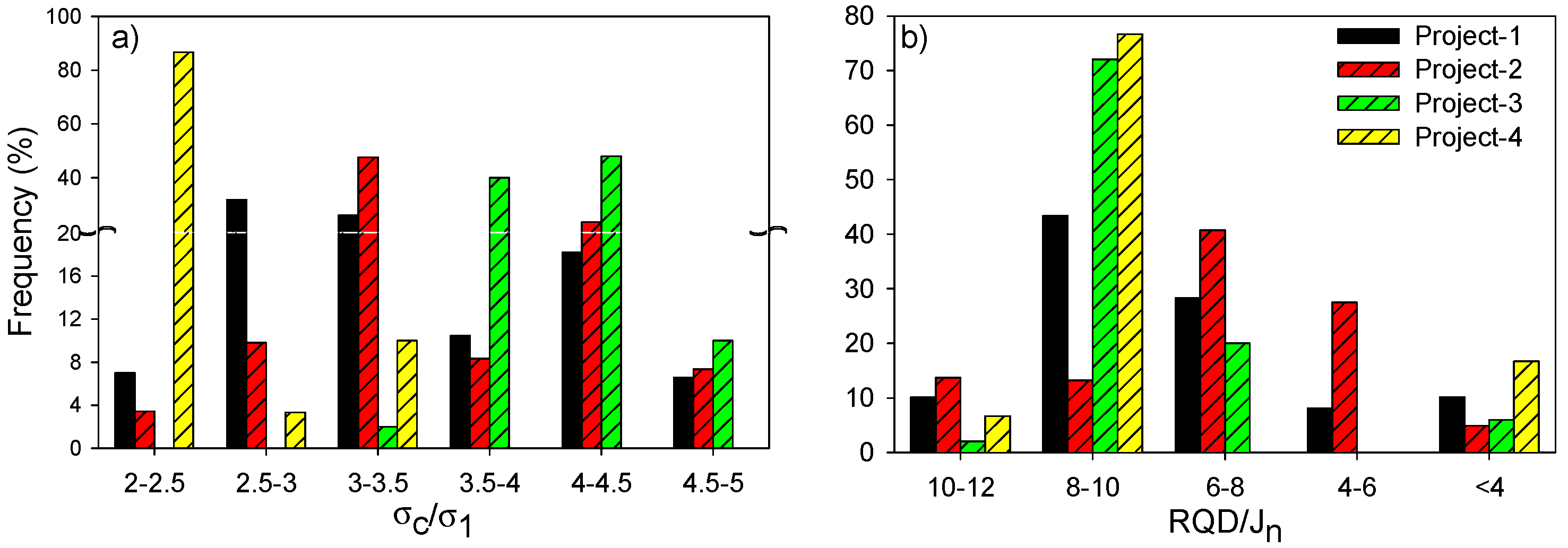
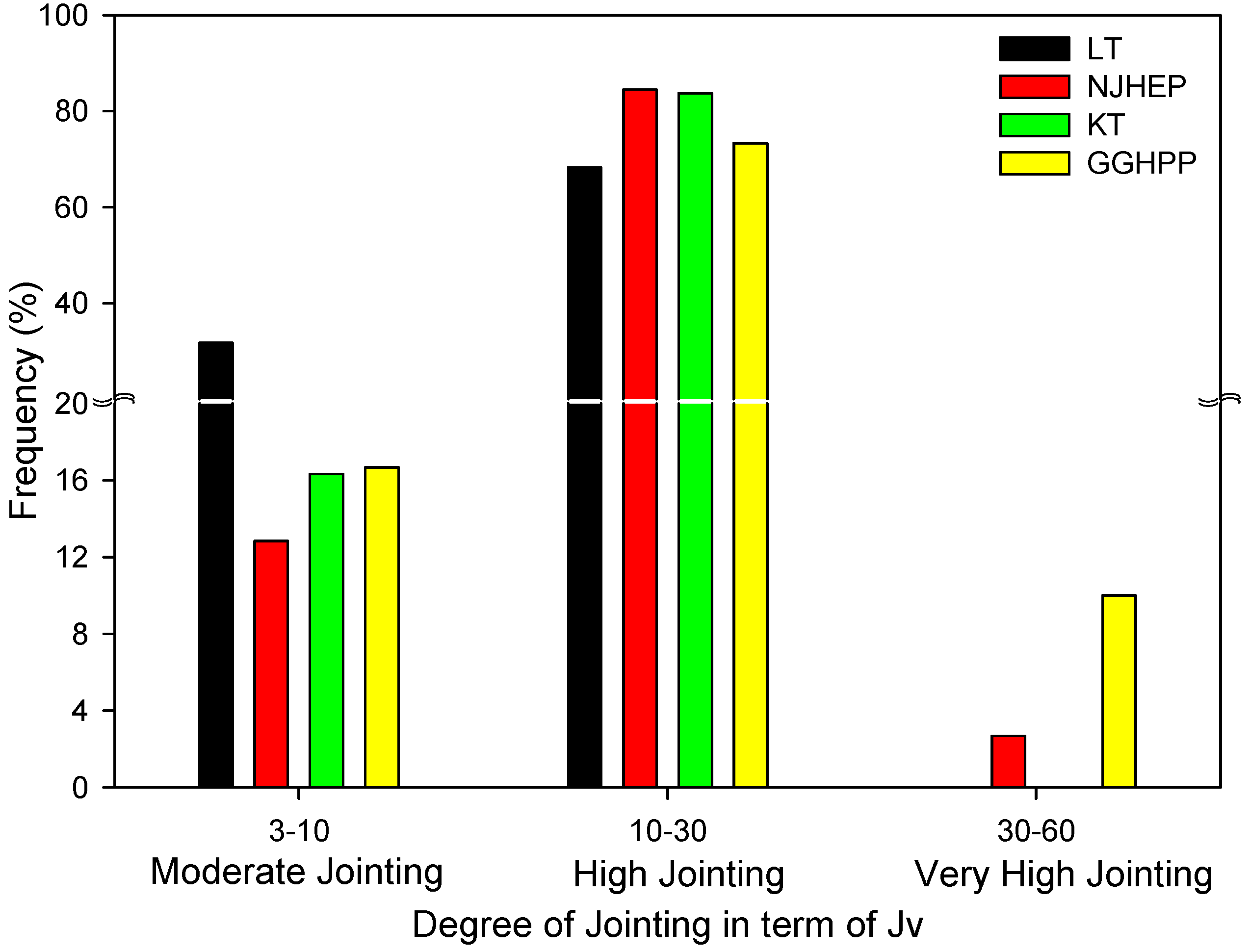
The results from seven boreholes (BDR-08, 10, 21, 22, 24, 25, and 26) along the diversion tunnels of Project 5 show that 75% of the
RQD/
Jn values were less than 16.5, and only 7.6% of the
RQD/
Jn values were greater than 25. Similarly, for Project 6, of 13 boreholes (BH-01, 02, 03, 04, 05, 08, 09, 10, 11, 12, 13, 15, 26), in most of them, the degree of jointing was high to very high, resulting in
RQD < 50%. Only BH-09 and BH-26 in Project 6 had predominantly moderate jointing, which corresponds to a range of
RQD from 50% to 75% [
37]. For simplicity and to reduce the number of cases that were numerically evaluated,
Jr = 3,
Ja = 1, and
Jw = 1 were used for empirical support design.
The average properties of the intact rock for different rock types of projects 5 and 6 are given in
Table 9.
For the numerical validation of Equations (22) and (23), different overburdens were used for different scenarios of
σc/
σ1, within the limitations of this study (5 >
σc/
σ1 > 2). For different
RQD/
Jn and
σc/
σ1 values,
SRF values were determined using Equations (22) and (23). Based on the calculated tunneling quality index (
Q or
Qc) from Equations (1) and (2), preliminary supports were determined from the support chart of the
Q system; the details are shown in
Table 10.
Table 11 shows the rock mass properties that were extrapolated from the intact rock strength properties of
Table 9, and the geological strength index (GSI) values through the generalized Hoek–Brown failure criterion [
54]. The GSI values that are shown in
Table 11 are for the particular cases of
Table 10, and are based on the rock mass fabric index approach, which was calculated from
RQD/
Jn and
Jr/
Ja values [
45].
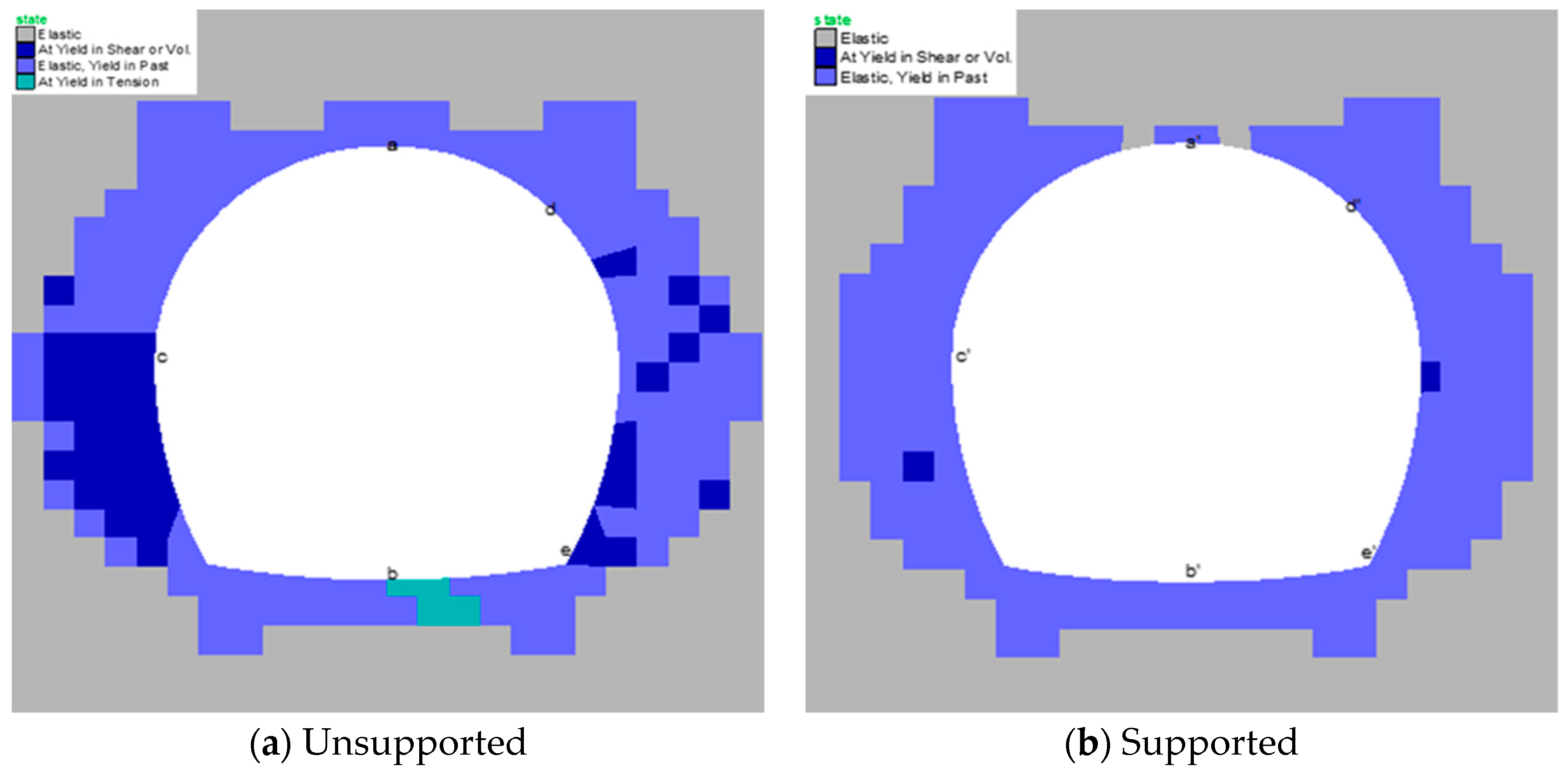
The empirically determined support system was used in numerical modeling to analyze the results before and after the support in terms of the plastic zones in the vicinity of the tunnels and displacement in rock mass. The total displacement at different points along the tunnel perimeter (
Figure 10) are shown in
Table 12. For the analysis, FLAC (Fast Lagrangian Analysis of Continua) version 7.0 is used. FLAC is an explicit two-dimensional (2D) finite difference program that is suited for sequential excavation modeling. A horseshoe-shaped tunnel was selected because it is a better shape for the drilling and blasting methods that are used in such circumstances, and is the most commonly used tunnel shape in Pakistan.
The two excavation stages (top heading and bench) and three construction steps (excavation, applying soft shotcrete and rock bolt, and hard shotcrete) in each stage are simulated for analysis. The model dimensions are 90 m × 80 m for both projects 5 and 6. The modified Hoek–Brown model was used for the analysis. This model is based on the nonlinear relation between major and minor principal stresses, σ1 and σ3, and the criterion is used for plastic yielding when σ3 is compressive. The fine mesh was simulated around the tunnel boundary for better results. The model was fixed at the sides and bottom, and vertical stresses (σyy) were applied at the top of the model. The in situ stress environment was created using gravity, σyy, and the FISH (a programming language embedded within FLAC that enables the user to define new variables and functions) function. During the three construction steps for each excavation stage, 40% 30%, and 30% relaxation were used.
To calculate the total displacement at points along the tunnel perimeter, the x and y displacement components were obtained from the grid points data. The plastic zones before and after support were analyzed for all four cases of the two projects. The plastic state zone was retrieved from the plot command using the zone condition in the model. For the SS-1 rock case of Project 6, the yield in shear was still the comparative maximum of all the cases, as shown in
Figure 10; however, with the application of support, this decreased enormously.
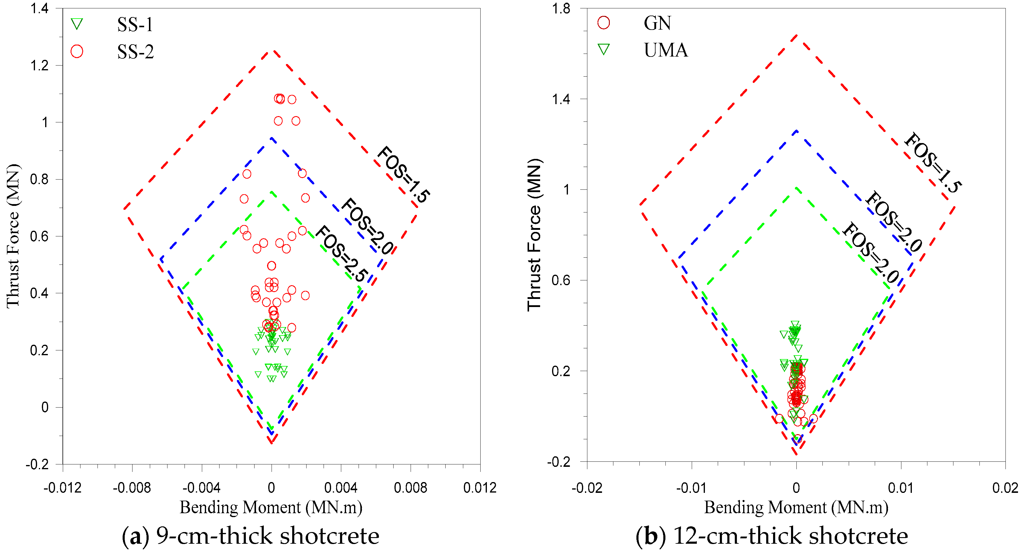
Capacity diagrams, which graphically represent the relationships between thrust-bending moments and thrust-shear forces, are used to evaluate the stability of liners [
55]. For this, the structure’s liner information was obtained from the utility function command. Based on the proposed shotcrete thickness from
Table 10, thrust-bending diagrams were plotted (
Figure 11) for shotcrete thicknesses of 12 cm and 9 cm for factor of safety (FOS) values equal to 1.5, 2, and 2.5.
5. Discussion
The application of rock mass classification in tunnel support design is now acceptable worldwide, and a number of empirical systems have been developed since the first classification system was developed by Terzaghi in 1946, which was known as rock load classification. The application of such systems is not universal, due to the case histories on which each system is based. However, a few systems, including RMR,
Q, and
RMi, have gotten international attention. Compared to the other classification systems, these systems have still been widely used in tunnel design since their development, because they are continuously upgraded in terms of characterizations or support, or both [
3]. The evaluations of the three systems indicate that the
Q and
RMi systems incorporate stress-related factors, making their application more suitable for tunnel support design, where stress is the major factor governing the ground behavior. However, these systems do not cover tunnels designed in jointed rock mass and high in situ stress fields. The two systems are limited by the case histories on which they are based. In this study, the application of these two systems are empirically extended from the relevant tunnel case records.
In the literature, the
SRF factor is either a function of
RQD/
Jn or
σc/
σ1. In this study, the empirical equation that was developed for the characterization of
SRF is a function of both
RQD/
Jn and
σc/
σ1, along with
σc.
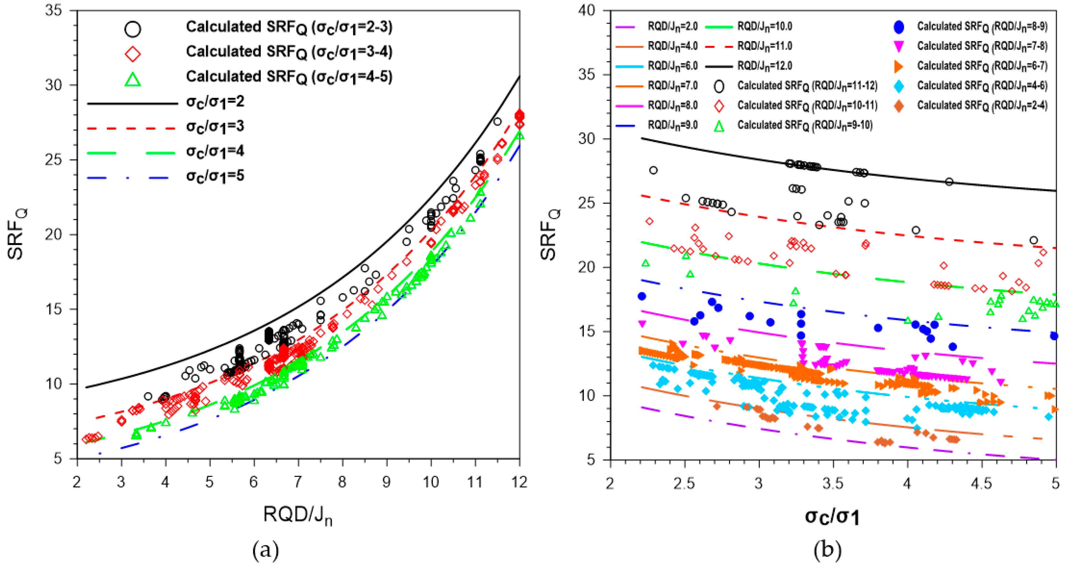
Figure 6a shows that
SRFQ (the
SRF value that was developed for the original
Q-system equation, Equation (1)) significantly increases with relative block size. A maximum change in
RQD/
Jn of less than seven results in a variation of 5.4 for
SRFQ, while for a maximum change in
RQD/
Jn greater than seven,
SRFQ varies by approximately 15.05, which is larger by a factor of about 2.75. A total
SRFQ change of 20.82 can be observed with
RQD/
Jn for a given value of
σc/
σ1. With an increase in
RDQ/
Jn, the difference of
SRFQ for different values of
σc/
σ1 is comparatively low for a given value of
RQD/
Jn.
An opposite trend can be seen in
Figure 6b. For
RQD/
Jn, the rate of decrease of
SRFQ with respect to low values of
σc/
σ1 is large compared to high values of
σc/
σ1. For a
σc/
σ1 value below 3.5, the maximum fluctuation in
σc/
σ1 for a given value of
RQD/
Jn results in a variation of the
SRFQ value of about 2.49. Fluctuation in
σc/
σ1 by an equal amount in its upper limit (above 3.5) can change
SRFQ by 1.35 approximately, which is about 1.84 times smaller. The maximum change in
SRFQ is 4.09 with
σc/
σ1 for any given value of
RQD/
Jn. The available data indicate that the maximum value of the relative block size is 12.
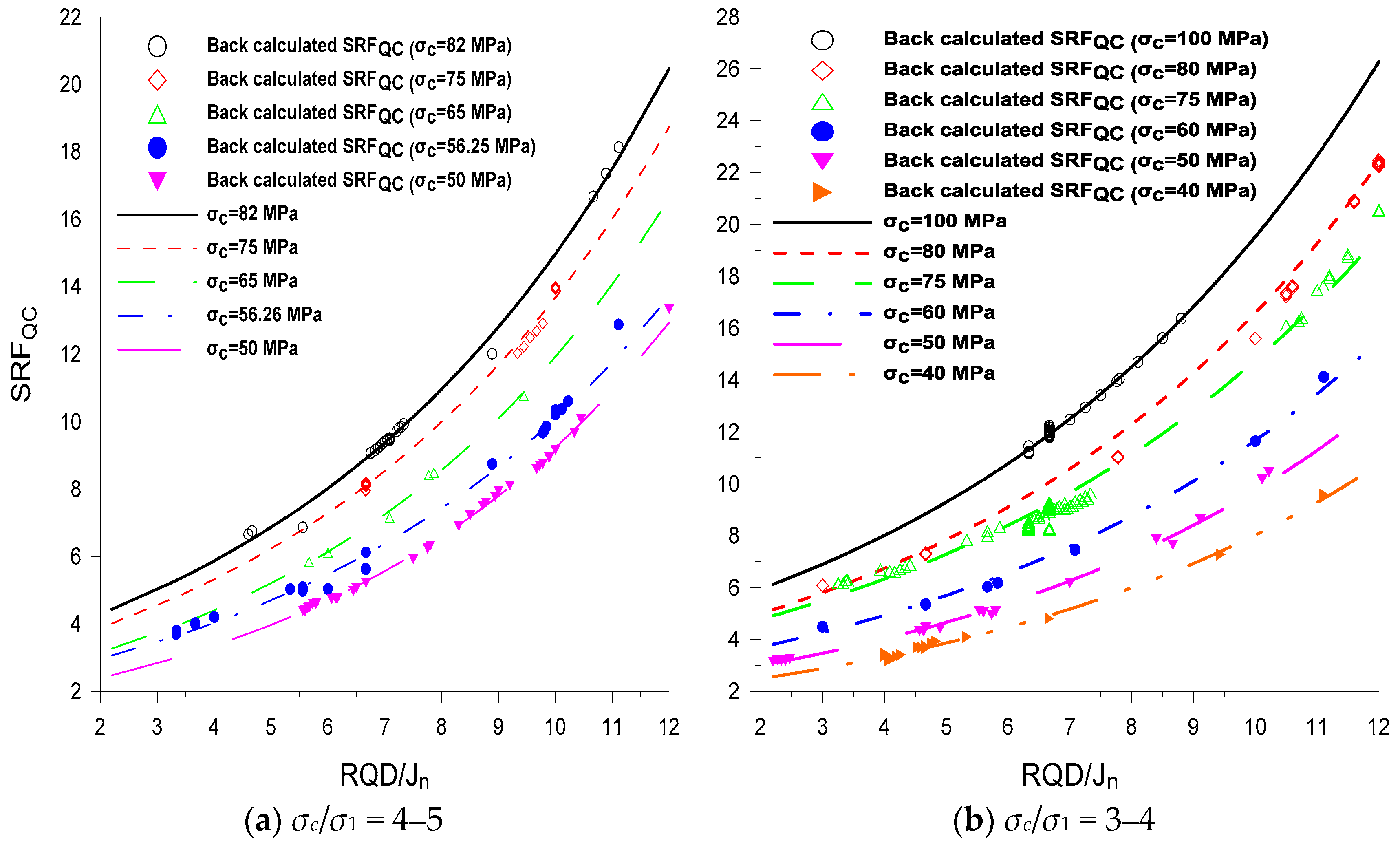
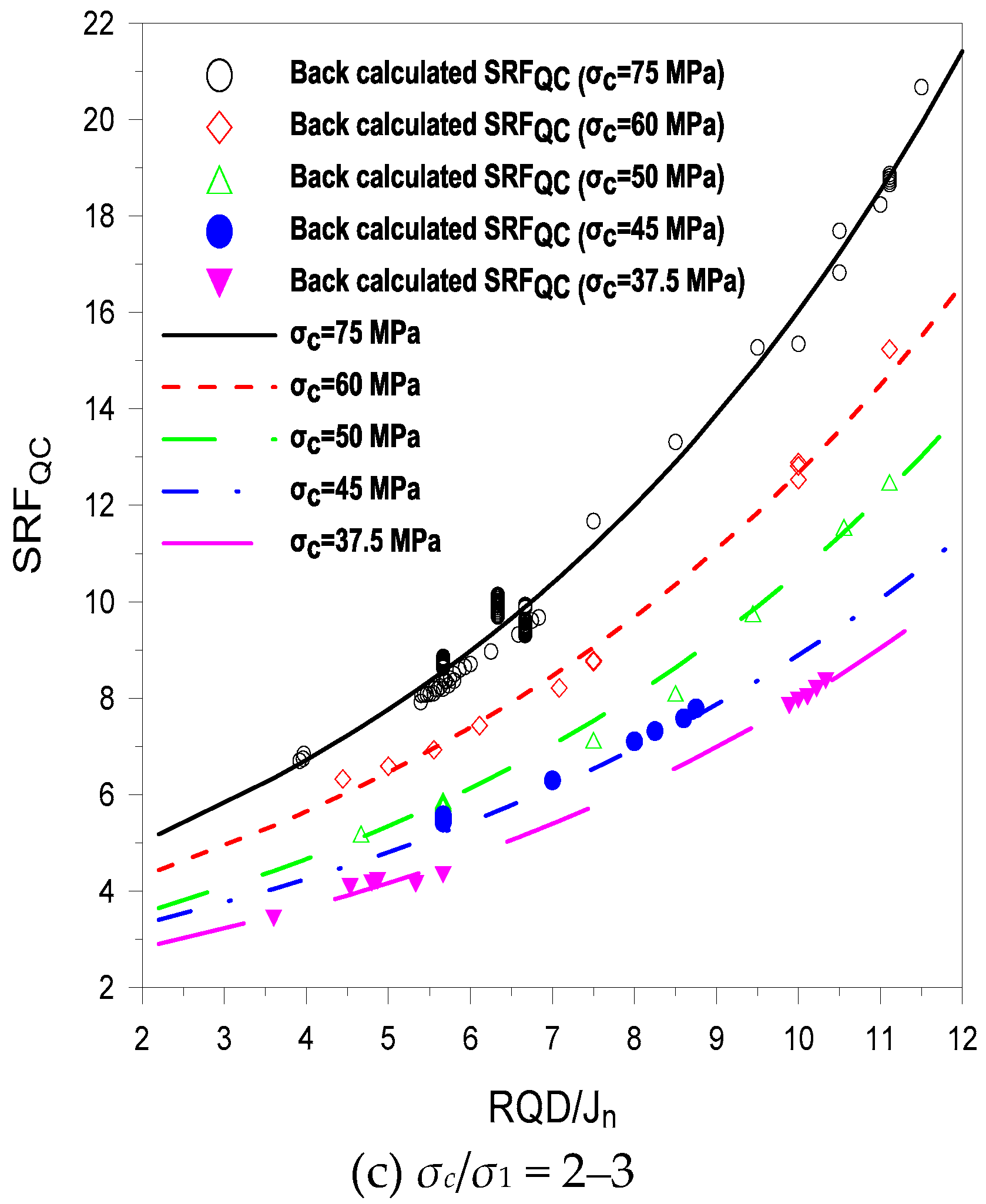
Figure 7 shows that the variation of
SRFQC with
RQD/
Jn also depends on
σc as well as
σc/
σ1. For the same value of
σc/
σ1, high principal stress (
σ1) requires rock with a high
σc value. The high level of stress means that more support is required, and hence, a high value of
SRFQC. The maximum variation of
SRFQC with
RQD/
Jn is 18.5 for
σc = 100 MPa, with
σc/
σ1 ranging from three to four (
Figure 7b), and the minimum variation is 7.38 for
σc = 37.5 MPa (
Figure 7c). During the design stage of a tunnel, when inadequate information exists, then, with knowledge of
σc (which is the most basic parameter to be determined) and the location of the tunnel,
Figure 7 can be used to approximate values of
SRFQC for different values of
RQD/
Jn. In the construction phase of a tunnel, when most of the information is in hand at the excavation face, Equations (22) and (23) can be used to calculate
SRFQC. The maximum rating of
σc is 100, as shown in
Table 3; therefore, the calculated
SRFQ and
SRFQC have the same value for tunnel sections where
σc = 100 MPa. In the remaining sections,
SRFQC <
SRFQ, and the difference depends on
σc.
The
RMi system uses SL in its structure for the stress factor (Equation (13)), and its ratings are shown in
Table 6. Comparing
Table 6 with
Table 2, SL is only applicable for the first three conditions of
Table 2 where
σc/
σ1 > 5. Equation (13) shows that a high value of SL is favorable, but it is not applicable when
σc/
σ1 < 5, as shown in
Table 2. The comparison of actual installed supports with those supports that are suggested by
RMi showed that the suggested support was heavier than the actual. The equations for the calculation of
Qc and
Gc are rewritten in such a way that each equation is the function of the same parameter, and a relation is developed between the two, keeping in view the limitation of data.
The extension of the two systems is based on Equations (22) and (23); therefore, these equations are used for determining the empirical supports of four rock units, using the
Q-system support chart. The support application is numerically evaluated in terms of a decrease in the total displacement at different points along the tunnel periphery, and in the plastic zone. The maximum decrease in total displacement occurred at the tunnel crowns, with a value of 1.3 mm for the SS-2 rock unit of Project 6 (
Table 12). According to plasticity theory, a plastic zone occurs around a tunnel after excavation when the induced stresses exceed the rock mass strength. The application of empirically recommended support not only reduced the number of yield elements, but also substantially decreased the extent of the plastic zone in all of the cases. With support, yield in tension was not observed, while yield in shear was either zero or substantially reduced.
As can be seen from the capacity diagram in
Figure 11, none of the cases cross the limit of FOS = 1.5. The capacity diagram for the liner shows that for the SS-2 rock unit of Project 6, the dominant failure mode was in compression; however, it too does not cross FOS = 1.5. In the case of the GN rock unit of Project 5, the dominant failure mode was in tension, but FOS > 1.5.
6. Conclusions
RMR, Q, and RMi classifications are based on jointed rock mass data, and are extensively used in the support design of tunnels, but are not used in highly stressed, jointed environments due to the limitations of the relevant data on which these systems are based. As a result, applications of these systems are limited under such conditions.
The Q system does not provide SRF values for highly stressed, jointed rock mass. To extend the Q-system application for such a situation, empirical equations are suggested for SRF characterization in competent rock that has rock stress problems. For jointed rock mass, the relevant data from the four existing tunnel projects that already have supports installed are used. In the proposed equations, SRF depends upon the intact rock strength, the ratio of intact rock strength to the major principal stress, and the relative block size.
The stress level (SL) in the RMi system has no allowance for highly stressed, jointed rock mass. Accordingly, the RMi system recommends heavier support than what is already installed. Using SL ≈ 1/SRF, the ground quality factor decreases, which results in a heavier support.
Therefore, an alternate approach using a tunneling quality index support chart to extend application of the RMi system in highly stressed, jointed rock mass was used. The equations that were proposed in this study for SRF characterization were used for the rock quality index value determination, as applied to two tunnels that were in the design stage. The empirical support suggested by the rock quality index system support chart was numerically evaluated, and found that with application of that support, the total displacement and the extent of plastic zone decreased. The various thicknesses of shotcrete were also evaluated with a capacity diagram to confirm their stability.


