Review

Stable and Low-Spurs Optoelectronic Oscillators: A Review

State Key Laboratory of Information Photonics and Optical Communications, Beijing University of Posts and Telecommunications, Beijing 100876, China
*
Author to whom correspondence should be addressed.
Appl. Sci. 2018, 8(12), 2623; https://doi.org/10.3390/app8122623
Submission received: 12 November 2018 / Revised: 6 December 2018 / Accepted: 11 December 2018 / Published: 14 December 2018
(This article belongs to the Special Issue Microwave Photonics 2018)

Abstract

:
An optoelectronic oscillator (OEO) is an optoelectronic hybrid oscillator which utilizes ultra-low-loss fiber as an electro-magnetic energy storage element, overcoming the limits of traditional microwave oscillators in phase noise performance. Due to their ability to generate ultra-low phase noise microwave signal, optoelectronic oscillators have attracted considerable attentions and are becoming one of the most promising and powerful microwave signal sources. In this paper, we briefly introduce the operation principle and discuss current research on frequency stability and spurious suppression of optoelectronic oscillators.

1. Introduction

Oscillators, as energy conversion devices, can transform a continuous DC signal to a periodic analog signal [1,2], which is the core component of modern electronic systems, such as communication systems [3], radar [4], and electronic warfare [5]. Along with providing a clock signal for high-speed digital systems [6,7], oscillators can also be used as local oscillators for up-and-down frequency conversion [8,9], and a reference source in synchronous systems [10,11]. As the microwave electronic systems develop rapidly [8,9], these systems vigorously demand higher levels of oscillator performances, including frequency range, stability, and phase noise.
In general, the energy storage characteristics of resonators determine the quality of the signals produced by oscillators [12]. In order to generate high-quality microwave signals, energy storage elements with a high Q-factor and low losses are essential. The energy storage of contemporary microwave oscillators, including dielectric oscillators [13] and crystal oscillators [14,15], are mostly based on electronic and acoustic resonators. When these resonators operate at frequencies above GHz, the energy storage characteristics will drop sharply, and then the phase noise of generated high-frequency microwave signals will deteriorate. Owing to microwave photonic technology [16], optoelectronic oscillators (OEOs), utilizing low-loss optical fiber for energy storage, were originally proposed by Steve Yao and Lute Maleki in 1996 [17,18]. Moreover, the OEO is deemed as one of the most promising and powerful methods [19] in producing low-phase noise microwave signal from hundreds of MHz to 100 GHz.
We have reviewed the literature of optoelectronic oscillators of the past two decades involving several well-known and recognized academic societies, including but not limited to IEEE, OSA, and SPIE. We will briefly introduce the fundamental structure and operation principle of optoelectronic oscillators and review current research on the enhancement of OEO performance, including spurious mode suppression and long-term frequency stability, which have not been summarized in detail before. We sincerely hope that this review will help the broad masses of researchers to understand and improve OEO more effectively.
This paper is organized as follows: Section two demonstrates the fundamental setup and the principle of an optoelectronic oscillator and briefly summaries the research status; section three analyzes the improvement of OEOs, including spurious suppression and frequency stabilization; Section 4 presents the conclusions and looks into the future.

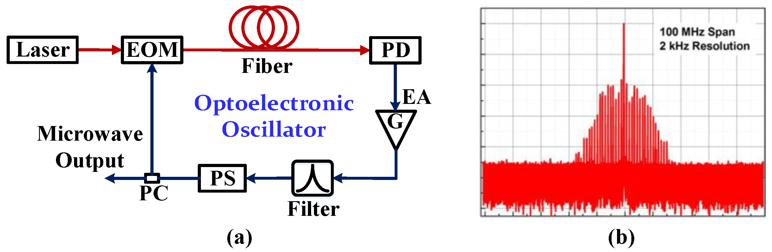
2. Optoelectronic Oscillators

The schematic diagram of a fundamental optoelectronic oscillator is shown in Figure 1a and Figure 1b shows the example spectrum of a fundamental OEO. An optoelectronic regenerative feedback loop consists of a laser, an electro-optical modulator (EOM), a spool of fiber, a photodetector (PD), a band-pass filter, an electronic amplifier, a phase shifter (PS) and a power coupler (PC). The optical carrier is provided by the laser and then introduced into the electro-optical modulator. The oscillation signal of an OEO plays the role of driving RF signal which modulates the optical carrier. Then, the modulated optical signal is produced and transmitted through the high Q optical energy storage element, such as low loss long fiber. The photodetector is the bridge between the optical and electrical domain, which achieves photo-electric conversion. The recovered RF oscillation signal is then amplified, filtered, and phase shifted, respectively. Finally, the RF signal is fed back to the electro-optical modulator for the loop close and output via the power coupler. Once the amplitude and phase conditions of oscillation are met, the OEO will export a high-quality microwave signal. Because of the long fiber with low transmission loss as the energy storage element, an OEO can obtain long delay, and then the generated microwave signal features high spectral purity and low phase noise. The recorded ultra-low phase noise of the most advance OEO is −163 dBc/Hz @ 6 kHz offset for a 10-GHz carrier via 16-km optical fiber [20]. In addition, the energy storage performance of fiber has nothing to do with the microwave oscillation frequency, since the frequency band of microwave signal is much lower than optical frequency. Therefore, the phase noise performance of OEO is theoretically independent of the oscillation frequency [18].
After nearly two decades of continuous exploration, the research on optoelectronic oscillators has made rapid progress [21]. However, it is still necessary to improve the performance and stability of OEOs for wider application. Nowadays, research on OEOs mainly focuses on the reduction of phase noise [22], the improvement of spurious suppression ratio [23], frequency stability [24], the expansion of oscillating frequency [25], frequency tuning [26], miniaturization [27], and multi-frequency oscillation [28]. This paper mainly analyzes and summarizes the work of spurious suppression and frequency stabilization for optoelectronic oscillators.

3. Improvement of Optoelectronic Oscillators

For OEOs, the employment of low-loss, long optical fiber as the ultra-high Q electro-magnetism energy storage element ensures the low phase noise performance. However, it inevitably brings some knotty problems including rock-ribbed spurs and inferior frequency instability at the same time. For the wider practical application of OEOs, suppressing spurious mode and improving long-term frequency stability are two burning questions.

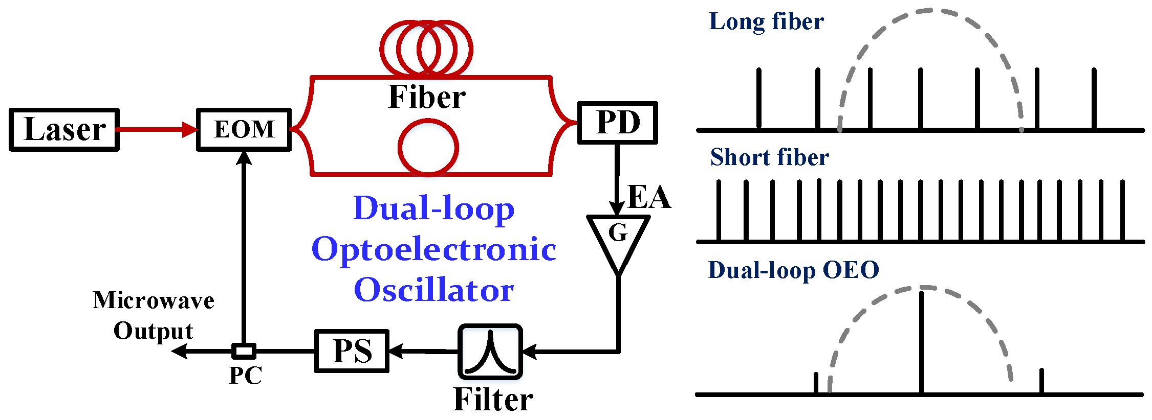
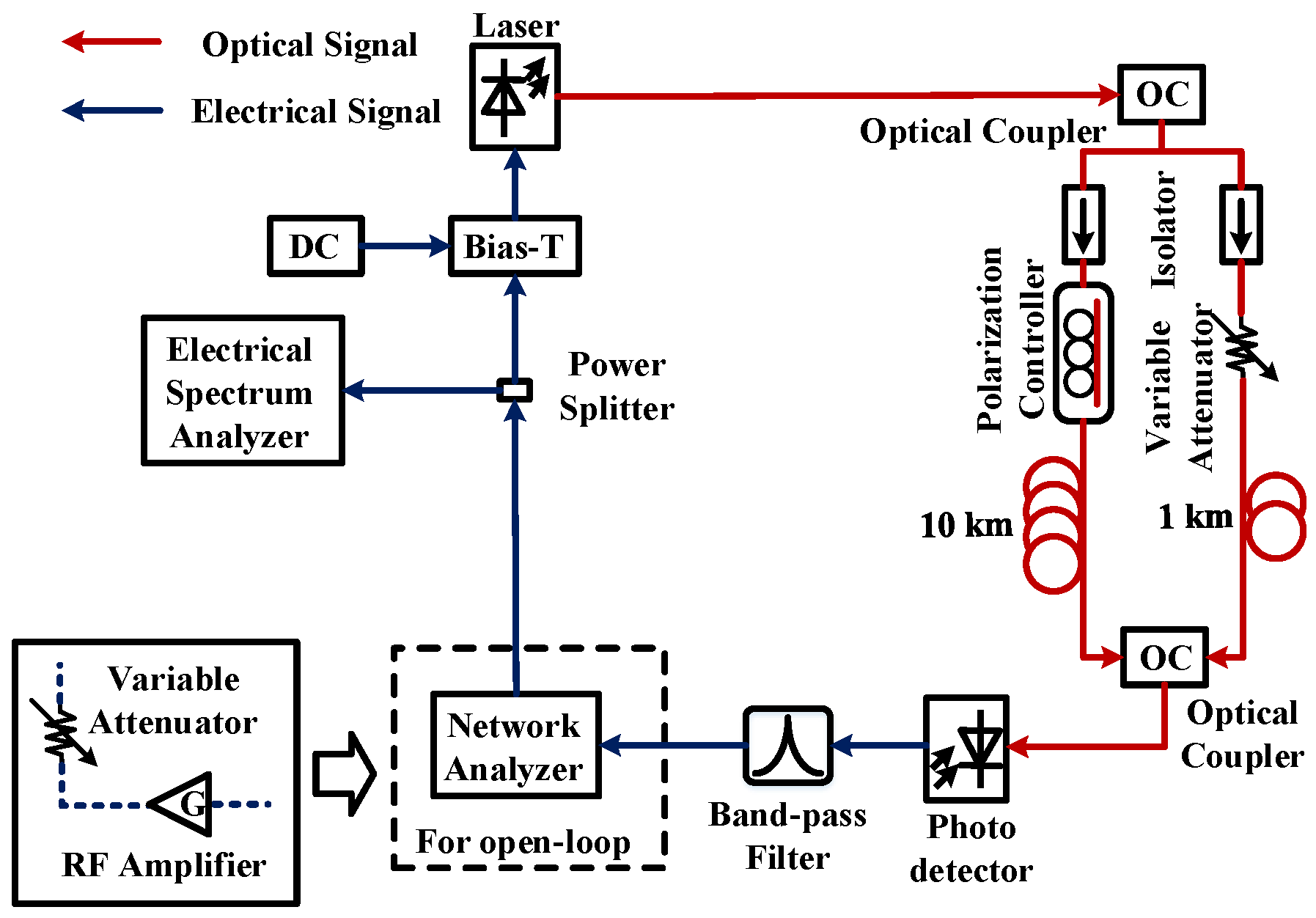
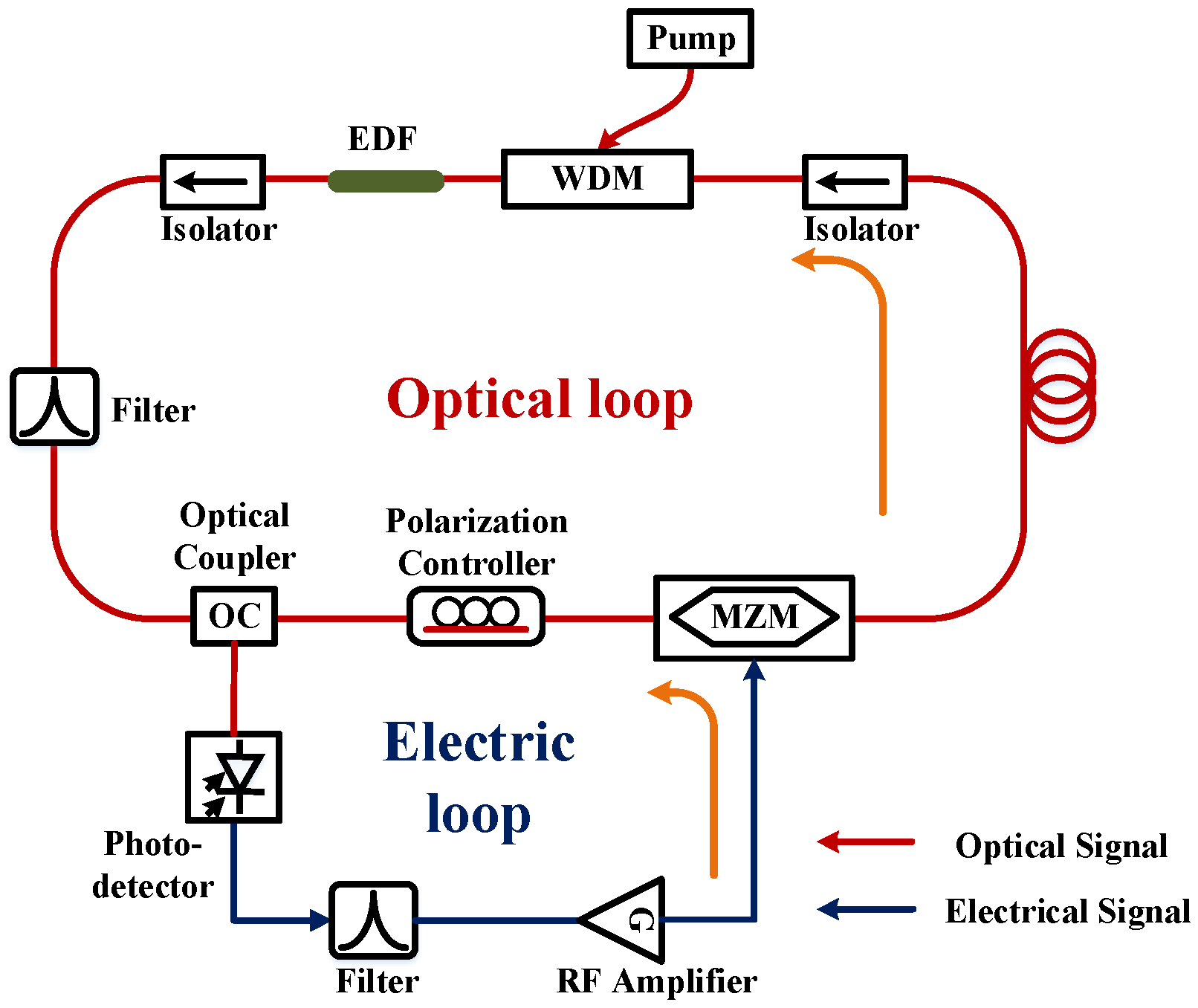
3.1. Spurious Suppression

In order to produce a microwave signal with superior phase noise performance, an OEO is supposed to equip high Q-value oscillating cavity and achieve long delay time, which is proportional to the length of the fiber. When fiber length and oscillation frequency are L and f respectively, Q-value of oscillating cavity can be represented as
Q = 2 π f τ = 2 π f n L c
where τ and n are respectively the delay time and the effective refractive index of fiber, and c represents the speed of light. It can be summarized from Equation (1), that the longer the fiber the greater the delay time and the Q-value. However, the mode spacing of OEO Δ f is inversely proportional to the length of fiber, which can be expressed as
Δ f = 1 τ = c n L .
For example, the mode spacing of an OEO is about 50 kHz when the length of fiber is 4 km, and the Q-value of band-pass filter in the OEO loop is accordingly required to be as high as 100,000 so as to obtain 10-GHz single mode oscillation. Nevertheless, Q value of available microwave band-pass filter will decrease along with the operating frequency, and it is difficult to achieve microwave band-pass filtering with a bandwidth of the order of 10 kHz and then reject the unwanted oscillation modes [29,30,31]. Several methods have been proposed to settle this problem, such as dual-loop OEOs [32], coupled optoelectronic oscillators (COEOs) [33], injection-locking technique [34], and high-Q microwave photonic filter [35].
The dual-loop OEOs are implemented based on two fiber loops with different lengths in parallel as shown in Figure 2. These fiber loops have their own phase match conditions and mode spacing. Because of the gain-competition between these series of modes, only the frequency components that meet the phase matching requirements of both loops can stably oscillate. In order to achieve the oscillating mode match and realize the Vernier effect, the precise control of the loop lengths is necessary. As a result, the mode spacing of multi-loop OEO is expanded, alleviating the high demand for the Q-value of filter, and the spurs of OEOs can be effectively suppressed. In [36], Y. Jiang et al. reported a dual-loop OEO scheme employing a pair of polarization-beam splitter and combiner, and the spurious suppression ratio was improved to about 60 dB. However, the overall Q-value of the dual-loop OEO is between the long-loop OEO and the short-loop OEO. Compared to the single-loop OEO with a long fiber, the Q value of dual-loop OEO decreases and the phase noise correspondingly increases. To overcome the diminution of phase-noise performance, Jun-Hyung Cho et al. found that the spurious modes of dual-loop OEO can be reduced while maintaining the phase noise performance by properly controlling the gains of the OEO, as shown in Figure 3, after investigating the open-loop characteristics. Through the precise open-loop gain control, they demonstrated the suppression of spurious modes by more than 21 dB [37].
To further shorten the fiber length, Steve Yao designed a compact architecture named compact optoelectronic oscillator (COEO) [33], which is another solution to suppress spurs as shown in Figure 4. The COEO includes an active mode-locked laser loop and an optoelectronic feedback loop. To enhance the Q value and decrease the phase noise of the oscillator, several hundred meters of fiber are employed in the active mode-locked laser loop. Since COEO employs shorter fiber to store energy, the oscillation mode spacing is correspondingly enlarged and the spurs can be suppressed effectively via conventional microwave band-pass filter. In order to further suppress the spurs of COEO, our research group proposed that an optical pulse power feedforward scheme can effectively suppress such side-modes of COEO as shown in Figure 5 [38], through which the mode-locked optical pulse is reversely intensity-modulated by itself, resulting in fast power limiting. The spurs can be suppressed as much as 40 dB in a 10-GHz COEO. Recently, we proposed and experimentally demonstrated a simple COEO scheme embedding a free-running microwave oscillator as shown in Figure 6 [39]. The COEO and the embedded microwave oscillator share the same electronic feedback and then inject each other to achieve mutual injection locking effect. Due to the single-mode oscillation of the free-running oscillator, the multi-mode oscillation of COEO is eased and the spurious noise can be significantly suppressed to below −120 dBc.
According to the frequency pulling effect, the spurious suppression of OEO can be achieved by injecting another signal, which has close frequency with some oscillating mode of OEO, commonly referred to as injection locking. In [40], M. Fleyerl et al. employed an electronic oscillator to injection-lock the OEO without a narrow-band filter as shown in Figure 7, and the spurs levels closest to the carrier frequency were about 55 dB smaller than those obtained by a self-sustained OEO employing electronic filter having the Q-factor of 720. However, the phase noise of the final oscillating signal would be limited to some extent due to the injection signal. Therefore, a dual injection-locked OEO (DIL-OEO) scheme [41] proposed by O. Okusaga et al. has been employed to achieve, not only low phase noise, but also low spurs via two OEO systems with different length oscillating cavities. The two OEOs inject and affect each other to achieve mutual injection-locking as shown in Figure 8. The steady-state power fluctuation in either loop will alter both the phase noise and spur levels of the DIL-OEO. In addition, both oscillation modes of the slave and master loops need accurate matches to ensure the phase locking effect.
High-Q microwave photonic filters such as whispering gallery mode (WGM, Figure 9) resonator [26], Fabry-Perot etalon [35], and atomic cells [42] can simultaneously implement energy storage and frequency selection for OEOs, replacing the conventional long fiber and microwave filter. In [43], M. Bagnell et al. utilized a Fabry–Perot etalon with a finesse of 100,000 as a photonic filter in a conventional single loop OEO as shown in Figure 10. The etalon provided a high Q-value microwave band-pass filtering at harmonics of 1.5 GHz free spectral range for oscillation frequency in the range of 6 to 60 GHz. There were no visible spurious modes above the noise floor, despite employing as long as a 2 km fiber delay. In [44], we proposed an ultra-high Q optoelectronic hybrid band-pass filter to suppress a spurious mode of OEO as shown in Figure 11. The 3-dB bandwidth of the proposed optoelectronic hybrid band-pass filter was about 1 MHz at 29.99-GHz center frequency, and the spurious suppression ratio can reach more than 83 dBc.

3.2. Frequency Stabilization

The superior phase noise performance of OEO can be attributed to the employment of low-loss, long optical fiber with high Q factor. However, the effective refractive index and length of fiber are sensitive to ambient temperature variations. Meanwhile, the oscillating cavity is easily affected by mechanical vibrations, stress, and device aging, which make the cavity length change and the oscillating frequency drift. Besides, in view of the low Q-value microwave band-pass filter, there would be multiple spurious modes in the gain bandwidth of OEO loop. The change of the cavity length will cause some spurious modes to obtain sufficient oscillation gain and replace the original frequency, leading to stochastic frequency hopping. Those characters have a non-negligible contribution to oscillation frequency drift, and they would greatly deteriorate the long-term frequency stability of optoelectronic oscillators [45]. In terms of improving the long-term frequency stability of OEOs, it is essentially necessary to control the effective cavity length of the OEO and reduce the impact of the ambient environment.
Several methods of improving the frequency stability of OEOs have been proposed, including temperature-insensitive fiber [46], thermal stabilization [47,48] and phase-locked loop [49]. Employing temperature-insensitive fiber in the OEOs can diminish the impact of ambient environment variation. In [46], M. Kaba et al. replaced the common single-mode fiber with solid-core photonic crystal fiber (SC-PCF) serving as energy storage element for OEO and the frequency stability was improved to some extent. Nevertheless, the phase noise of OEOs with SC-PCF is less-than-ideal due to the sacrifice of Q value resulting from larger transmission loss. Thermal stabilization, including temperature control and system isolation for OEOs, is also an effective solution to relieve the negative influence of ambient environment variation. For instance, Steve. Yao et al. placed the OEO system in a bubble-filled box to isolate the effects of sound and vibration [47]. In [48], D. Eliyahu et al. made use of resistive heaters and temperature controllers for the high-Q devices of OEO, such as the optical fiber and the narrow band-pass microwave filter. The free-running OEO under thermal stabilization featured a short-term frequency stability of 0.02 ppm. The slope of frequency versus. temperature improved from −8.3 ppm/°C for non-thermally stabilized OEO to −0.1 ppm/°C. However, it is worth mentioning that the means of thermal stabilization inevitably increased bulk and power consumption, which brings new issues. Meanwhile, the performance for frequency stability of OEOs could not meet higher requirements in special applications, which means that further stabilization methods would still be necessary, as shown in Figure 12 [49].
The phase-locked-loop (PLL) technique is the most practical and has been widely used in the frequency stabilization for microwave oscillators. The active PLL control circuit can lock the oscillation signal generated by OEO to an external highly-stable reference source. The final signal of PLL-based OEO has the same frequency stability with the external reference while maintaining phase noise performance at high-offset frequencies. Our research group proposed and demonstrated a novel broadband and wide-range feedback tuning scheme on the strength of a dual parallel Mach-Zehnder modulator (DPMZM) and optical band-pass filter for PLL stabilization of tunable OEO as shown in Figure 13 [50]. The PLL-based stabilization for OEO was achieved at different oscillating frequencies and the long-term frequency stability was indeed improved with more than four orders of magnitude without any thermal control. However, the PLL-aided OEO in [50], which is realized by controlling the bias voltage of the modulator would affect the light intensity, thereby negatively affecting the OEO oscillating state. The analog voltage-controlled phase shifter is typical in adjusting the cavity length in the PLL-based OEO. In [51], A. Bluestone et al. proposed a novel voltage-controlled oscillator (VCO) which is an OEO utilizing phase-locked loop architecture as shown in Figure 14. The OEO demonstrated excellent phase-noise performance at high-offset frequencies, while the PLL reduces the phase noise at low-offset frequencies. Nevertheless, the maximum phase shift range of the commercial microwave phase shifter decreases along with the operating frequency, and it will be too narrow to compensate the frequency drift for OEOs at a high operating frequency. Therefore, we proposed a frequency conversion pair to improve the frequency-drift compensation range for the PLL-stabilized OEO as shown in Figure 15 [52]. The cavity length is adjusted by controlling the phase shift of oscillation signal at relatively low frequency via frequency division and frequency multiplication. Moreover, the stability of the locked optoelectronic oscillator was improved from 4.1 × 10⁻⁷ to 1.1 × 10⁻¹⁰ at 1000 s averaging time. In order to achieve the frequency stability of millimeter-wave (MMW) signal produced by OEO, we proposed a novel frequency-de-multiplication OEO (FD-OEO) scheme as shown in Figure 16 [53]. The oscillation of the FD-OEO can be maintained without optical first-order sidebands, which would help to simplify the photonic-assisted frequency multiplication process while providing a wide frequency compensation range for the millimeter-wave signal. The overlapping Allan deviation of the generated 40-GHz MMW signal reaches 1.38 × 10⁻¹² at the average time of 100 s as shown in Figure 17.

4. Conclusions

Low phase noise RF oscillators are required in multiple applications, ranging from radar and Global Position System (GPS) to high performance analog to digital converters to trans-oceanic data transmission. Since 1996, the OEO has been investigated for applying to many different fields requiring low phase noise RF signals. However, inferior frequency stability and rock-ribbed spurs, which result from the inherent structure, hinder the practicability of the OEO. In this article, we analyzed and summarized the research on the improvement of frequency stability and spurious suppression of OEOs to contribute and provide new insights for future work. The wide-band frequency tunability and stability of optoelectronic oscillators are a critical issue that need to be solved urgently.

Author Contributions

Investigation and Writing, A.L.; Resources and Review, J.D.; Supervision and Project Administration, K.X.

Funding

This research was partially funded by National Natural Science Foundation of China (NSFC) Program (61501051, 61625104 and 61821001); Fundamental Research Funds for the Central Universities (2018RC22), Fund of State Key Laboratory of Information Photonics and Optical Communications (BUPT No. IPOC2017ZT01); State Key Laboratory of Advanced Optical Communication Systems and Networks, China Postdoctoral Science Foundation (No. 2018T110074).

Conflicts of Interest

The authors declare no conflict of interest.

References

  1. Chirikov, B.V. A universal instability of many-dimensional oscillator systems. Phys. Rep. 1979, 52, 263–379. [Google Scholar] [CrossRef]
  2. Sazonova, V.; Yaish, Y.; Üstünel, H. A tunable carbon nanotube electromechanical oscillator. Nature 2004, 431, 284–287. [Google Scholar] [CrossRef] [Green Version]
  3. Roh, W.; Seol, J.Y.; Park, J.; Lee, B.; Kim, Y.; Aryanfar, F. Millimeter-wave beamforming as an enabling technology for 5G cellular communications: Theoretical feasibility and prototype results. IEEE Commun. Mag. 2014, 52, 106–113. [Google Scholar] [CrossRef]
  4. Scheer, J.A.; Kurtz, J.L. Coherent Radar Performance Estimation; Artech House: Norwood, MA, USA, 1993. [Google Scholar]
  5. Vig, J.R. Military applications of high accuracy frequency standards and clocks. IEEE Trans Ultrason. Ferroelectr. Freq. Control 1993, 40, 522–527. [Google Scholar] [CrossRef] [PubMed]
  6. Da Dalt, N.; Harteneck, M.; Sandner, C.; Wiesbauer, A. On the jitter requirements of the sampling clock for analog-to-digital converters. IEEE Trans. Circuits Syst. I Fundam. Theory Appl. 2002, 49, 1354–1360. [Google Scholar] [CrossRef]
  7. Shoop, B. Photonic Analog-to-Digital Conversion; Springer: Berlin, Germany, 2001. [Google Scholar]
  8. Weyers, S.; Lipphardt, B.; Schnatz, H. Reaching the quantum limit in a fountain clock using a microwave oscillator phase locked to an ultra-stable laser. Phys. Rev. A 2009, 79, 031803. [Google Scholar] [CrossRef]
  9. Clark, T.R.; Carruthers, T.F.; Matthews, P.J.; Duling, I.N. Phase noise measurements of ultra-stable 10 GHz harmonically mode-locked fiber laser. Electron. Lett. 1999, 35, 720–721. [Google Scholar] [CrossRef]
  10. Holloway, C.L.; Simons, M.T.; Gordon, J.A.; Wilson, P.F.; Cooke, C.M.; Anderson, D.A.; Raithel, G. Atom-based RF electric field metrology: From self-calibrated measurements to subwavelength and near-field imaging. IEEE Trans. Electromagn. Compat. 2017, 59, 717–728. [Google Scholar] [CrossRef]
  11. Sartorius, B. All-optical clock recovery for 3R optical regeneration. In Proceedings of the Optical Fiber Communication Conference, Anaheim, CA, USA, 17 March 2001. [Google Scholar]
  12. Drexhage, K.H. Influence of a dielectric interface on fluorescence decay time. J. Lumin. 1970, 1, 693–701. [Google Scholar] [CrossRef]
  13. Kajfez, D.; Guillon, P. Dielectric Resonators; Artech House, Inc.: Norwood, MA, USA, 1986. [Google Scholar]
  14. Filler, R.L. The acceleration sensitivity of quartz crystal oscillators: A review. IEEE Trans. Ultrason. Ferroelectr. Freq. Control 1988, 35, 297–305. [Google Scholar] [CrossRef] [PubMed]
  15. Vig, J.R. Quartz crystal resonators and oscillators for frequency control and timing applications. A tutorial. NASA STI/Recon Tech. Rep. N 1994, 9. [Google Scholar]
  16. Capmany, J.; Novak, D. Microwave photonics combines two worlds. Nat. Photonics 2007, 1, 319. [Google Scholar] [CrossRef]
  17. Yao, X.S.; Maleki, L. Optoelectronic microwave oscillator. J. Opt. Soc. Am. B Opt. Phys. 1996, 13, 1725–1735. [Google Scholar] [CrossRef]
  18. Yao, X.S.; Maleki, L. Optoelectronic oscillator for photonic systems. IEEE J. Quantum Electron. 1996, 32, 1141–1149. [Google Scholar] [CrossRef]
  19. Maleki, L. Sources: The optoelectronic oscillator. Nat. Photonics 2011, 5, 728–730. [Google Scholar] [CrossRef]
  20. Eliyahu, D.; Seidel, D.; Maleki, L. Phase noise of a high performance OEO and an ultra-low noise floor cross-correlation microwave photonic homodyne system. In Proceedings of the IEEE Conference on International Frequency Control Symposium, Honolulu, HI, USA, 19–21 May 2008; pp. 811–814. [Google Scholar]
  21. Devgan, P. A review of optoelectronic oscillators for high speed signal processing applications. ISRN Electron. 2013, 2013, 1–16. [Google Scholar] [CrossRef]
  22. Eliyahu, D.; Seidel, D.; Maleki, L. RF amplitude and phase-noise reduction of an optical link and an opto-electronic oscillator. IEEE Trans. Inf. Theory 2008, 56, 449–456. [Google Scholar] [CrossRef]
  23. Kim, J.Y.; Jo, J.H.; Choi, W.Y.; Sung, H.K. Dual-loop dual-modulation optoelectronic oscillators with highly suppressed spurious tones. IEEE Photonics Technol. Lett. 2012, 24, 706. [Google Scholar] [CrossRef]
  24. Romisch, S.; Kitching, J.; Ferre-Pikal, E. Performance evaluation of an optoelectronic oscillator. IEEE Trans. Ultrason. Ferroelectr. Freq. Control 2000, 47, 1159–1165. [Google Scholar] [CrossRef]
  25. Zhu, D.; Pan, S.; Ben, D. Tunable frequency-quadrupling dual-loop optoelectronic oscillator. IEEE Photonics Technol. Lett. 2012, 24, 194–196. [Google Scholar] [CrossRef]
  26. Eliyahu, D.; Maleki, L. Tunable, ultra-low phase noise YIG based opto-electronic oscillator. In Proceedings of the IEEE MTT-S International Microwave Symposium, Philadelphia, PA, USA, 8–13 June 2003; pp. 2185–2187. [Google Scholar]
  27. Ilchenko, V.S.; Byrd, J.; Savchenkov, A.A.; Matsko, A.B.; Seidel, D.; Maleki, L. Miniature oscillators based on optical whispering gallery mode resonators. In Proceedings of the IEEE International Frequency Control Symposium, Honolulu, HI, USA, 19–21 May 2008; pp. 305–308. [Google Scholar]
  28. Zhou, P.; Zhang, F.; Pan, S. A multi-frequency optoelectronic oscillator based on a single phase-modulator. In Proceedings of the Conference on Lasers and Electro-Optics, San Jose, CA, USA, 10–15 May 2015. [Google Scholar]
  29. Hosseini, S.E.; Banai, A. Analytical Prediction of the Main Oscillation Power and Spurious Levels in Optoelectronic Oscillators. J. Lightwave Technol. 2014, 32, 978–985. [Google Scholar] [CrossRef]
  30. Swanson, D.; Macchiarella, G. Microwave filter design by synthesis and optimization. IEEE Microw. Mag. 2007, 8, 55–69. [Google Scholar] [CrossRef]
  31. Bogataj, L.; Vidmar, M.; Batagelj, B. Opto-Electronic Oscillator with Quality Multiplier. IEEE Trans. Microw. Theory Tech. 2016, 64, 663–668. [Google Scholar] [CrossRef]
  32. Yao, X.S.; Maleki, L. Dual microwave and optical oscillator. Opt. Lett. 1997, 22, 1867–1869. [Google Scholar] [CrossRef] [PubMed]
  33. Yao, X.S.; Davis, L.; Maleki, L. Coupled optoelectronic oscillators for generating both RF signal and optical pulses. J. Lightwave Technol. 2000, 18, 73–78. [Google Scholar] [CrossRef]
  34. Sung, H.K.; Lau, E.K.; Wu, M.C. Optical single sideband modulation using strong optical injection-locked semiconductor lasers. IEEE Photonics Technol. Lett. 2007, 19, 1005–1007. [Google Scholar] [CrossRef]
  35. Dai, J.; Dai, Y.; Yin, F.; Zhou, Y.; Li, J.; Fan, Y.; Xu, K. Compact optoelectronic oscillator based on a Fabry–Perot resonant electro-optic modulator. Chin. Opt. Lett. 2016, 14, 110701. [Google Scholar]
  36. Yang, J.; Jin-Long, Y.; Yao-Tian, W.; Li-Tai, Z.; En-Ze, Y. An optical domain combined dual-loop optoelectronic oscillator. IEEE Photonics Technol. Lett. 2007, 19, 807–809. [Google Scholar] [CrossRef]
  37. Cho, J.; Kim, H.; Sung, H. Reduction of spurious tones and phase noise in dual-loop OEO by loop-gain control. IEEE Photonics Technol. Lett. 2015, 27, 1391–1393. [Google Scholar] [CrossRef]
  38. Dai, Y.; Wang, R.; Yin, F.; Dai, J.; Yu, L.; Li, J.; Xu, K. Side-mode suppression for coupled optoelectronic oscillator by optical pulse power feedforward. Opt. Express 2015, 23, 27589–27596. [Google Scholar] [CrossRef]
  39. Dai, J.; Liu, A.; Liu, J.; Zhang, T.; Zhou, Y.; Yin, F.; Dai, Y.; Liu, Y.; Xu, K. Supermode noise suppression with mutual injection locking for coupled optoelectronic oscillator. Opt. Express 2017, 25, 27060–27066. [Google Scholar] [CrossRef] [PubMed]
  40. Fleyer, M.; Sherman, A.; Horowitz, M.; Namer, M. Wideband-frequency tunable optoelectronic oscillator based on injection locking to an electronic oscillator. Opt. Lett. 2016, 41, 1993–1996. [Google Scholar] [CrossRef] [PubMed]
  41. Okusaga, O.; Adles, E.J.; Levy, E.C.; Zhou, W.; Carter, G.M.; Menyuk, C.R.; Horowitz, M. Spurious mode reduction in dual injection-locked optoelectronic oscillators. Opt. Exp. 2016, 19, 5839–5854. [Google Scholar] [CrossRef] [PubMed]
  42. Strekalov, D.; Aveline, D.; Yu, N.; Thompson, R.; Matsko, A.B.; Maleki, L. Stabilizing an optoelectronic microwave oscillator with photonic filters. J. Lightwave Technol. 2003, 21, 3052–3061. [Google Scholar] [CrossRef]
  43. Bagnell, M.; Davila-Rodriguez, J.; Delfyett, P.J. Millimeter-wave generation in an optoelectronic oscillator using an ultrahigh finesse etalon as a photonic filter. J. Lightwave Technol. 2014, 32, 1063–1067. [Google Scholar] [CrossRef]
  44. Liu, A.; Liu, J.; Dai, J.; Dai, Y.; Yin, F.; Li, J.; Zhou, Y.; Zhang, T.; Xu, K. Spurious Suppression in Millimeter-Wave OEO with a High-Q Optoelectronic Filter. IEEE Photonics Technol. Lett. 2017, 29, 1671–1674. [Google Scholar] [CrossRef]
  45. Eliyahu, D.; Sariri, K.; Kamran, A.; Tokhmakhian, M. Improving short and long term frequency stability of the optoelectronic oscillator. In Proceeding of the IEEE Conference on International Frequency Control Symposium and PDA Exhibition Jointly, New Orleans, LA, USA, 31 May 2002; pp. 580–583. [Google Scholar]
  46. Kaba, M.; Li, H.W.; Daryoush, A.S.; Vilcot, J.P.; Decoster, D.; Chazelas, J.; Bouwmans, G.; Quiquempois, Y.; Deborgies, F. Improving thermal stability of optoelectronic oscillators. IEEE Microw. Mag. 2006, 7, 38–47. [Google Scholar] [CrossRef]
  47. Yao, X.S.; Maleki, L. Multi-loop optoelectronic oscillator. IEEE J. Quantum Electron. 2000, 36, 79–84. [Google Scholar] [CrossRef]
  48. Eliyahu, D.; Sariri, K.; Taylor, J.; Maleki, L. Optoelectronic oscillator with improved phase noise and frequency stability. In Proceedings of the International Society for Optics and Photonics: Photonic Integrated Systems, San Jose, CA, USA, 28–30 January 2003; Volume 4998, pp. 139–148. [Google Scholar]
  49. Zhang, Y.; Hou, D.; Zhao, J. Long-term frequency stabilization of an optoelectronic oscillator using phase-locked loop. J. Lightwave Technol. 2014, 32, 2408–2414. [Google Scholar] [CrossRef]
  50. Xu, X.; Dai, J.; Dai, Y.; Yin, F.; Zhou, Y.; Li, J.; Yin, J.; Wang, Q.; Xu, K. Broadband and wide-range feedback tuning scheme for phase-locked loop stabilization of tunable optoelectronic oscillators. Opt. Lett. 2015, 40, 5858–5861. [Google Scholar] [CrossRef] [PubMed]
  51. Bluestone, A.; Spencer, D.T.; Srinivasan, S.; Guerra, D.; Bowers, J.E.; Theogarajan, L. An ultra-low phase-noise 20-GHz PLL utilizing an optoelectronic voltage-controlled oscillator. IEEE Trans. Microw. Theory Tech. 2015, 63, 1046–1052. [Google Scholar] [CrossRef]
  52. Dai, J.; Zhao, Z.; Zeng, Y.; Liu, J.; Liu, A.; Zhang, T.; Yin, F.; Zhou, Y.; Liu, Y.; Xu, K. Stabilized Optoelectronic Oscillator with Enlarged Frequency-drift Compensation Range. IEEE Photonics Technol. Lett. 2018, 30, 1289–1292. [Google Scholar] [CrossRef]
  53. Liu, J.; Liu, A.; Wu, Z.; Gao, Y.; Dai, J.; Liu, Y.; Xu, K. Frequency-demultiplication OEO for stable millimeter-wave signal generation utilizing phase-locked frequency-quadrupling. Opt. Express 2018, 26, 27358–27367. [Google Scholar] [CrossRef] [PubMed]
Figure 1. (a) The schematic diagram of a fundamental optoelectronic oscillator (OEO). EOM: electro-optical modulator. PD: photodetector. EA: electronic amplifier. PS: phase shifter. PC: power coupler. (b) The example spectrum of fundamental optoelectronic oscillator.
Applsci 08 02623 g001
Figure 2. The schematic diagram of dual-loop optoelectronic oscillator. EOM: electro-optical modulator. PD: photodetector. EA: electronic amplifier. PS: phase shifter. PC: power coupler.
Applsci 08 02623 g002
Figure 3. The schematic diagram of dual-loop optoelectronic oscillator based on open-loop gain control in [37]. OC: optical coupler. Reprinted with permission from Ref. [37], IEEE, 2018.
Applsci 08 02623 g003
Figure 4. The schematic diagram of coupled optoelectronic oscillator. EDF: erbium doped fiber. WDM: wavelength division multiplex.
Applsci 08 02623 g004
Figure 5. The schematic diagram of the COEO based on optical power feedforward technique. EDF: erbium doped fiber. WDM: wavelength division multiplex. OBPF: optical band-pass filter. MZM: Mach-Zehnder modulator. PD: photodetector. LNA: low noise amplifier. EBPF: electric band-pass filter. ELPF: electric low pass filter. Reprinted with permission from Ref. [38], OSA, 2018.
Applsci 08 02623 g005
Figure 6. The schematic diagram of the mutually injection-locked COEO. EDF: erbium doped fiber. WDM: wavelength division multiplex. Reprinted with permission from Ref. [39], OSA, 2018.
Applsci 08 02623 g006
Figure 7. The schematic diagram of the injection-locked OEO. PD: photodetector. PS: phase shifter. PC: power coupler. HPF: high-pass filter. Reprinted with permission from Ref. [40], OSA, 2018.
Applsci 08 02623 g007
Figure 8. The schematic diagram of the dual-injection-locked OEO. Reprinted with permission from Ref. [41], OSA, 2018.
Applsci 08 02623 g008
Figure 9. The schematic diagram of the OEO employing a WGM resonator. WGM: whispering gallery mode. PC: polarization controller. PD: photodetector. LNA: low noise amplifier. Reprinted with permission from Ref. [26], OSA, 2018.
Applsci 08 02623 g009
Figure 10. The schematic diagram of the OEO employing a Fabry–Perot etalon and Pound–Drever–Hall frequency stabilization. PC: polarization controller. IM: intensity modulator. VOD: variable optical delay. EDFA: erbium-doped fiber amplifier. AOM: acousto-optic modulator. PM: phase modulator. CIR: circulator. FPE: Fabry–Perot etalon. PD: photodetector. LPF: low-pass filter. PID: proportional–integral–derivative controller. VCO: voltage-controlled oscillator. Reprinted with permission from Ref. [43], IEEE, 2018.
Applsci 08 02623 g010
Figure 11. The schematic diagram of the millimeter-wave OEO employing an optoelectronic hybrid band-pass filter with ultra-high Q value. MZM: Mach-Zehnder modulator. PC: polarization controller. OC: optical coupler. DSF: dispersion shifted fiber. PD: photodetector. EA: electrical amplifier. ESA: electrical spectrum analyzer. Reprinted with permission from Ref, [44], IEEE, 2018.
Applsci 08 02623 g011
Figure 12. The schematic diagram of the long-term frequency stabilization for OEO based on temperature control and PLL techniques. EOM: electro-optical modulator. DDF: dispersion deduced fiber. PD: photodiode. LNA: low noise amplifier. BPF: band-pass filter. EC: electrical coupler. PS: power splitter. LPF: low-pass filter. PID: proportional-integral-derivative. Reprinted with permission from Ref. [49], IEEE, 2018.
Applsci 08 02623 g012
Figure 13. The schematic diagram of the feedback tune scheme in PLL stabilization of OEO [50]. LD: laser diode. MZM: Mach-Zehnder modulator. DSF: dispersion-shifted fiber. PD: photodetector. EA: electrical amplifier. BPF: band-pass filter. EC: electronic coupler. ESA: electrical spectrum analyzer. PID: proportional-integral-derivative regulator module. Ref: microwave reference. Reprinted with permission from Ref. [50], OSA, 2018.
Applsci 08 02623 g013
Figure 14. The schematic diagram of the phase-locked loop architecture utilizing OEO as a voltage-controlled oscillator (VCO). MZM: Mach-Zehnder modulator. PC: polarization controller. PD: photodetector. EA: electrical amplifier. ESA: electrical spectrum analyzer. Reprinted with permission from Ref. [51], IEEE, 2018.
Applsci 08 02623 g014
Figure 15. Schematic diagram of the stabilized OEO scheme based on the FCP with equivalent wide frequency-compensation range [52]. MZM: Mach-Zehnder modulator. DSF: dispersion-shifted fiber. PD: photodetector. EA: electronic amplifier. PC: power combiner. BPF: band-pass filter. FD: frequency divider. VCPS: voltage controlled phase shifter. Att: attenuator. FM: frequency multiplier. PS: power splitter. Ref: microwave reference. FS: frequency synthesizer. PID: proportional-integral-derivative regulator module. Reprinted with permission from Ref. [52], IEEE, 2018.
Applsci 08 02623 g015
Figure 16. Schematic diagram of the stabilized millimeter-wave OEO scheme in [53]. MZM: Mach-Zehnder modulator. DSF: dispersion-shifted fiber. PD: photodetector. EA: electronic amplifier. PC: power combiner. BPF: band-pass filter. FD: frequency divider. VCPS: voltage controlled phase shifter. PID: proportional-integral-derivative regulator module. Reprinted with permission from Ref. [53], OSA, 2018.
Applsci 08 02623 g016
Figure 17. (a) The overlapping Allan deviation of the OEO system. (b) Comparison of phase noise for the OEO system. Reprinted with permission from Ref. [53], OSA, 2018.
Applsci 08 02623 g017

