Article

Off-Design Modeling and Simulation of Solar Absorption-Subcooled Compression Hybrid Cooling System

1
School of Electric Power, South China University of Technology, Guangzhou 510640, China
2
Guangdong Province Key Laboratory of High Efficient and Clean Energy Utilization, South China University of Technology, Guangzhou 510640, China
3
Guangdong Province Engineering Research Center of High Efficient and Low Pollution Energy Conversion, Guangzhou 510640, China
*
Author to whom correspondence should be addressed.
Appl. Sci. 2018, 8(12), 2612; https://doi.org/10.3390/app8122612
Submission received: 30 October 2018 / Revised: 2 December 2018 / Accepted: 10 December 2018 / Published: 13 December 2018
(This article belongs to the Special Issue Sciences in Heat Pump and Refrigeration)

Abstract

:
The solar absorption-subcooled compression hybrid cooling system (SASCHCS) is potentially an economical solution for high-rise buildings. The hybrid system is subjected to off-design operation frequently, owing to the changes in solar irradiance and cooling demand. However, a large amount of iterations and difficult convergence are encountered in the traditional off-design modeling. Hence, our present study contributes to the development of an off-design model that is exact and can be solved conveniently. A novel modeling method based on the combination of an absorption subsystem described by the characteristic equation and a compression subsystem modeled by the lumped parameter method is proposed. A prototype and corresponding experimental system are developed to verify the model. A good agreement between the theoretical result and test data is displayed. The maximum deviation is less than 4%. Subsequently, the performance of the facility for different operating conditions is simulated and analyzed. We found that the subcooling power relies significantly on the compressor speed, i.e., a reduction by 58.6% when the compressor speed reduces by 80%. In addition, a high temperature and low flow rate of cooling water in the compression subsystem is adverse to the performance of the hybrid system. Our study can serve as the foundation for the operational analysis of the solar absorption-subcooled compression hybrid cooling system as well as promote its development.

1. Introduction

Recently, building energy consumption of modern cities has increased remarkably, owing to the economic development and improvement of living standards, e.g., the energy consumption of a residential building is up to 25.2% of the total energy consumption in Hong Kong [1]. In a modern city, the energy consumed in high-rise buildings increases significantly because the number of high-rise buildings increases rapidly owing to the increasing urban population and land price [2]. Because approximately 50% of building energy consumption is caused by air conditioning [3], it is essential to reduce the consumption of refrigeration systems used in high-rise buildings for the sustainable development of a modern city.
Solar cooling technology is considered a promising method to decrease the consumption of air conditioning, owing to the coincident trends of solar irradiance and cooling demand. In addition, the solar LiBr/H2O absorption chiller is thought to be highly suitable for large-scale buildings, among the available solar thermal cooling systems [4]. However, the application of a solar-absorption chiller in high-rise buildings is accompanied by financial constraints. The operational cost of solar cooling (primarily produced by the natural gas) exceeds that of traditional air conditioning [5]. Because the investment cost of solar cooling is higher than that of air conditioning, the solar/natural gas driven absorption chiller is considered infeasible for high-rise buildings.
Shirazi [6] suggested solar refrigeration aided by electric energy as an alternative for high-rise buildings. In this solution, the absorption chiller is driven by solar energy, and a vapor compression chiller is employed to provide auxiliary cooling [7]. It was demonstrated that the payback period of the abovementioned system reduced by 61.3% compared with that of a solar/natural-gas-driven absorption chiller owing to the efficient use of auxiliary electricity energy. Because the payback period of the Shirazi solution is up to 36.2 years, we [8] proposed another system called the solar-absorption-subcooled compression hybrid cooling system (SASCHCS) as a more economical solution for high-rise buildings. The operating principle of SASCHCS is approximately similar to that of a vapor-compression chiller with dedicated mechanical subcooling [9]. The most remarkable advantage of the SASCHCS is its high performance as an absorption subsystem and the utilization of low-grade solar energy owing to the high evaporator temperature of the absorption chiller, thus resulting in the enhanced energy reduction [10]. Further, it was found that the product cost flow rate of the SASCHCS is superior to that of the Shirazi solution when they are used in high-rise buildings [11]. Compared with solar photovoltaic (PV) cooling, which is thought to be the most economical solar refrigeration technique available in recent times [12], the net present value of the SASCHCS is 50.04% greater than that of the solar PV chiller [13]. On the other hand, the exergoeconomic design principle of SASCHCS was presented to make the system more cost-effective [14]. Especially, the exergoeconomic-optimized criterion of the absorption chiller was analyzed in detail for the hybrid system used in the low-rise building, since the performance of the absorption subsystem reduces dramatically with the rise of its size [15]. Moreover, the 3E design of size in the absorption subsystem based on the annual data was carried out to make the SASCHCS work more efficiently with relatively low cost in the entire operation period [16].
The SASCHCS suffers from off-design operation frequently because of the variation in hot water conditions as well as the cooling demand of buildings. Accordingly, the off-design model of a hybrid system is highly important to solve the operational issue, i.e., the quasi-static simulation of daily operation as well as the impact of the operating strategy. A parametric model of the absorption-subcooled compression hybrid cycle was built by Xu [17]. Subsequently, we [8] combined the abovementioned model and the empirical equation of the cooling capacity in the absorption subsystem to develop the SASCHCS model. Because such models depend on the fixed heat transfer temperature difference, it is difficult to derive the exact off-design performance of the system. Therefore, the traditional off-design modeling of the refrigeration system is done by the lumped parameter describing each component according to the size and heat transfer characteristics. Although the abovementioned method is used widely in the off-design modeling of a normal absorption chiller and vapor compression chiller [18,19,20], it is unfeasible for the SASCHCS. First, the number of iterations for model solving is largely owed to the increased components (approximately seven heat exchangers), i.e., the number of iterations is up to 107 even when the iteration number of each component is only 10, thus leading to the long solving time. Next, the convergence becomes extremely difficult as the operating condition deviates severely from the design condition owing to the complicated iteration. Consequently, it is essential to simplify the iteration to develop the off-design model of the hybrid system. Because the off-design modeling of the SASCHCS relies primarily on the coupling of the cooling output in the absorption subsystem and the thermodynamic characteristics of the compression subsystem component, the iteration can be simplified if the absorption subsystem is treated as a black box and is described by a simple equation that avoids complicated calculations, i.e., the characteristic equation [21] or the empirical expression [22]. Inspired by this idea, we [23] modeled and simulated the hybrid system with some simplifications, in which the absorption subsystem is hypothesized to be a subcooler with fixed subcooling power, and the entire system is equivalent to a vapor compression chiller with a subcooler. It was demonstrated that the solving time reduces significantly and the model converged easily in the overall conditions.
We found that the abovementioned methodology is effective for off-design modeling of the SASCHCS. Therefore, we attempted to build the off-design model of the hybrid system in the previous foundation. The system is described by coupling the characteristic equation of the absorption subsystem and the lumped parameter model of the compression subsystem. Subsequently, a prototype and its corresponding experimental system are developed to verify the model. Moreover, the thermodynamic performance for different conditions is simulated and analyzed in detail. The novelty of our present study is the development of an exact and easily solved off-design model for the SASCHCS. It is mentioned that the off-design model is not dynamic but quasi-static because the model is mainly employed to analyze the performance for different conditions instead of variation processes. This study can serve as a foundation for the operation analysis of the SASCHCS as well as promote its development.

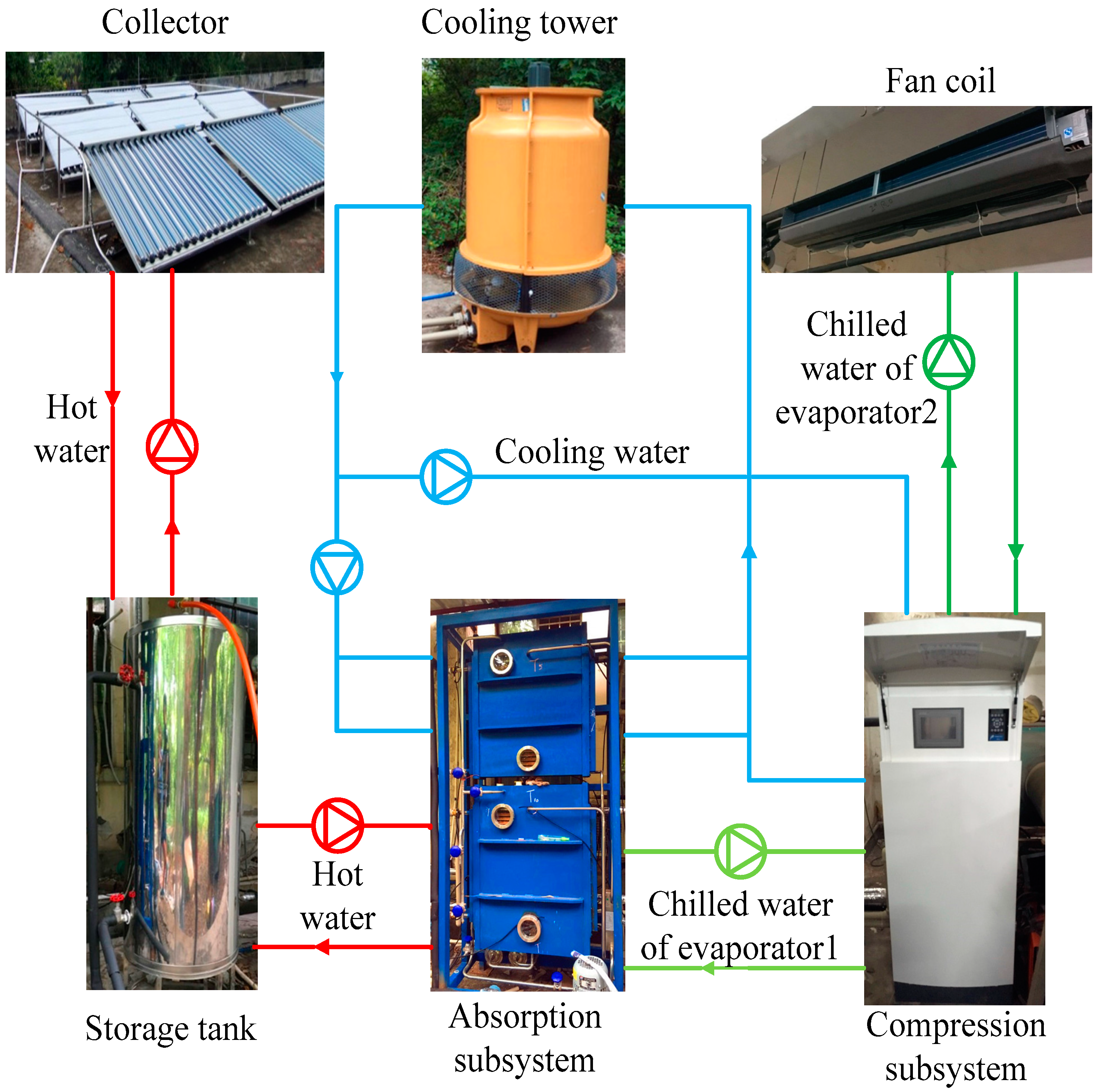
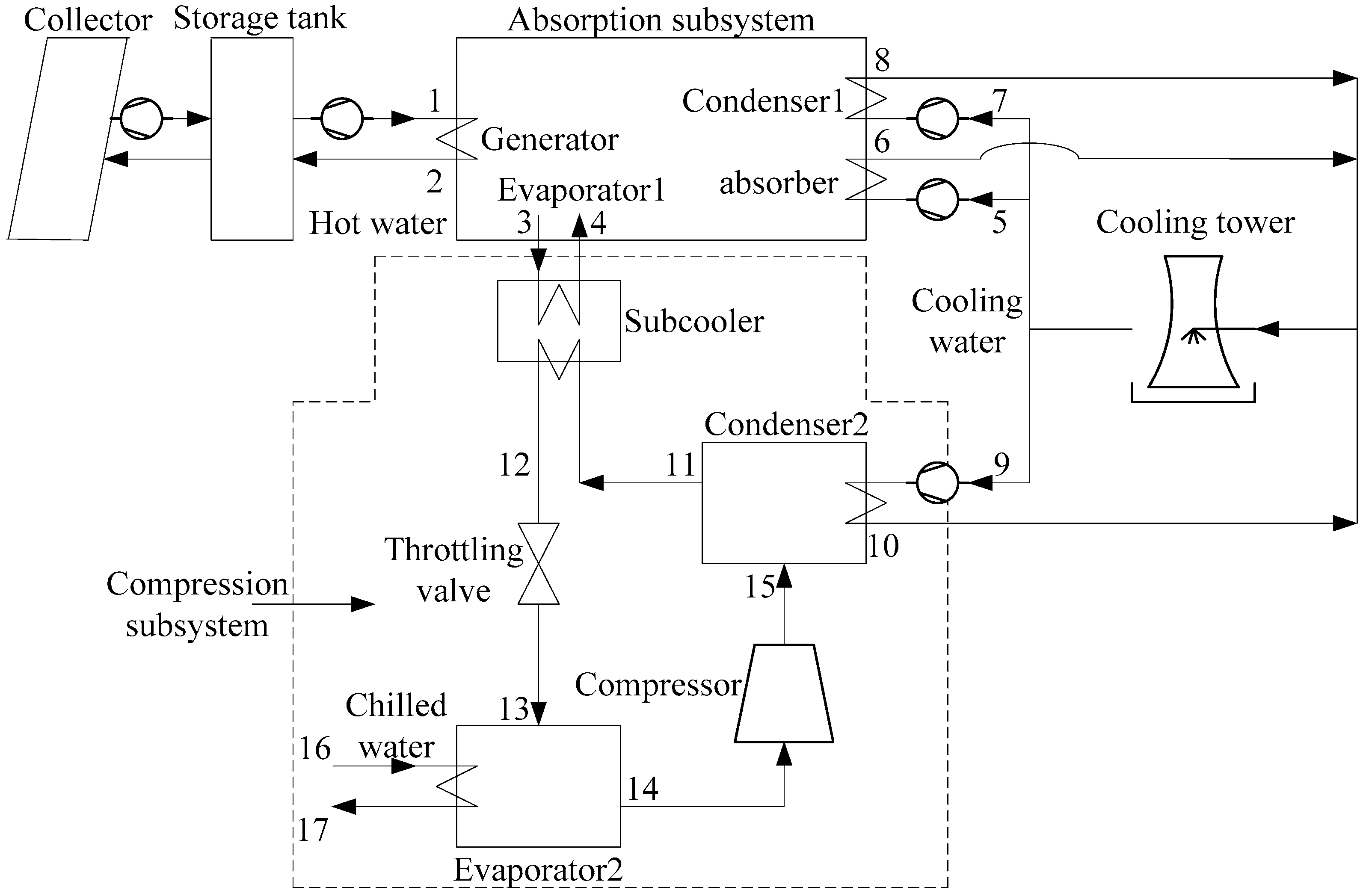
2. Prototype of SASCHCS

The prototype of the SASCHCS is developed to verify the model. The corresponding prototype and its schematics are exhibited in Figure 1 and Figure 2, respectively. The prototype consists of the collector, storage tank, absorption subsystem, compression subsystem, cooling tower, fan coil, water pump, tube, and valve. The condition of the prototype is listed in Table 1. It should be noticed that the UA for different heat exchangers is obtained by the regression of operational data.
The collector, produced by Shandong Linuo-Paradigma Co. Ltd. (Shandong, China), is the compound parabolic collector (CPC). The total aperture area of the CPC array is 27 m2. The operating fluid of the CPC is water. The volume of the storage tank is 0.2 m3.
The absorption subsystem, a LiBr/H2O single effect absorption chiller, is developed by the cooperation of our team and the Guangzhou Institute of Energy Research. It is driven by solar energy exclusively and the size is based on the scale of the collector. The generator, condenser, evaporator, and absorber are the horizontal falling film of the heat exchanger. Further, its solution-heat exchanger is the plate-heat exchanger. The cooling capacity of the absorption subsystem is employed as the subcooling power in the compression subsystem.
The compression subsystem is produced by Jiangsu CSE & CAFULL Air Conditioning Co. Ltd. (Jiangsu, China) Its refrigerant is R410A. The evaporator, condenser and subcooler of the compression subsystem are the plate heat exchanger as well. The compressor is the direct-current (DC) frequency conversion scroll compressor. The rated cooling capacity of the compression subsystem is 34 kW and the compressor speed is 4200 rpm. However, the experimental flow rate of the chilled water is insufficient to match with the rated output. Therefore, the maximum compressor speed is controlled at 1800 rpm in the experiment to avoid an excessively low evaporator temperature and the consequent frosting of the evaporator. Additionally, the cooling capacity of the hybrid system is delivered to the room by the fan coil. A cooling tower is used to cool the absorber and tow condensers in parallel.
The flow rates of all the external fluids in the prototype were tested by the turbine flowmeter. Additionally, the inlet/outlet temperature of the internal/external fluid was measured by the thermocouple attached in the wall of the copper tube (wrapped by the thermal insulation material). The detailed information of the test equipment is demonstrated in Table 2. In particular, the discharge temperature of the compressor was tested by the compression subsystem itself and is shown in the data display screen.

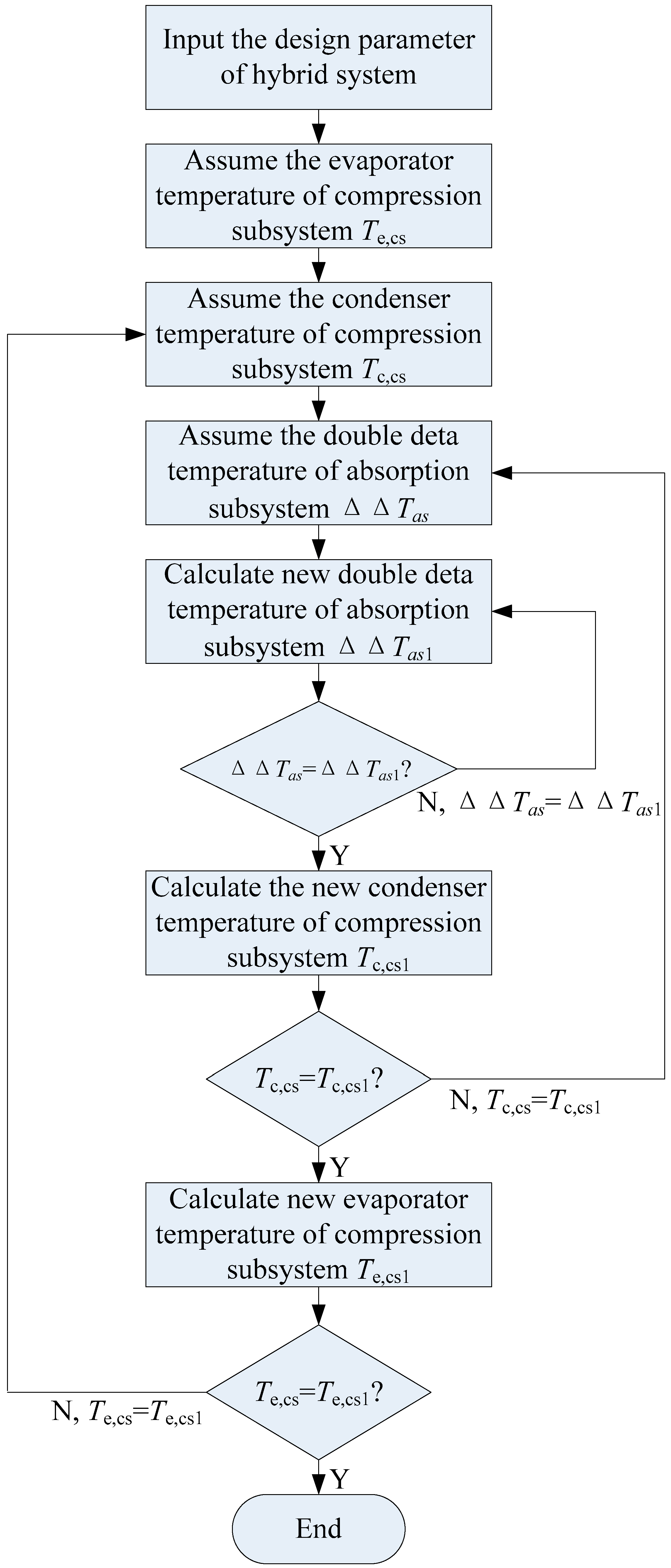
3. Off-Design Model of SASCHCS

The off-design model of the SASCHCS was established based on the following assumptions: (1) steady state; (2) the operating fluids at both the exit of the condenser and the evaporator in the compression subsystem are saturated; (3) the pressure loss of the pipeline and heat exchanger is neglected; and (4) the heat transfer of the system and the surroundings are not considered.

3.1. Modeling of Absorption Subsystem

The characteristic equation, a convenient method for the off-design simulation of the absorption chiller, was employed in the modeling of the absorption subsystem. In the characteristic equation method, the absorption chiller was treated as a black box, and the heat load of the component was calculated by the temperature as well as the flow rate of the external fluid [21,24].
The heat load of the generator, condenser, evaporator and absorber are described as follows:
Q h e , a s = ( U A ) h e , a s z h e , a s | T h e , a s , e f , a v g T h e , a s , i f , a v g |
Here, the absolute guarantees that the temperature difference is positive.
In addition, the heat loads of the generator, condenser and absorber can be expressed as a function of cooling capacity in the absorption subsystem:
Q g , a s = G Q e , a s + Q l o s s , a s
Q c , a s = C Q e , a s
Q a , a s = A Q e , a s + Q l o s s , a s
Here, the variables A , C and G are thought to be constant, and can be obtained by the operational data of the absorption chiller [21]. We found that A , C and G equal 1.1, 1.078, and 1.178, respectively, by the regression of the prototype’s experimental data.
The cooling output of the absorption subsystem is expressed as follows:
Q e , a s = s Δ Δ T a s α Q l o s s , a s = s ( Δ Δ T a s Δ Δ T a s , min )
The parameter Δ Δ T a s can be calculated by the temperature of the external fluid:
Δ Δ T a s = T g , a s , e f , a v g T a , a s , e f , a v g B ( T c , a s , e f , a v g T e , a s , e f , a v g )
Here, the variable B is 1.15 for the LiBr/H2O solution.
The parameter Δ Δ T a s , min relies on Δ Δ T a s [24]:
Δ Δ T a s , min = 1.9 + 0.01 Δ Δ T a s
The variable s and α depend on the size of the heat exchanger:
s = 1 G ( U A ) g , a s z g , a s + A ( U A ) a , a s z a , a s + B [ C ( U A ) c , a s z c , a s + 1 ( U A ) e , a s z e , a s ]
α = [ 1 ( U A ) g , a s z g , a s + 1 ( U A ) a , a s z a , a s ] s
The coefficient of performance (COP) of the absorption subsystem is
C O P a s = Q e , a s / Q g

3.2. Modeling of Compression Subsystem
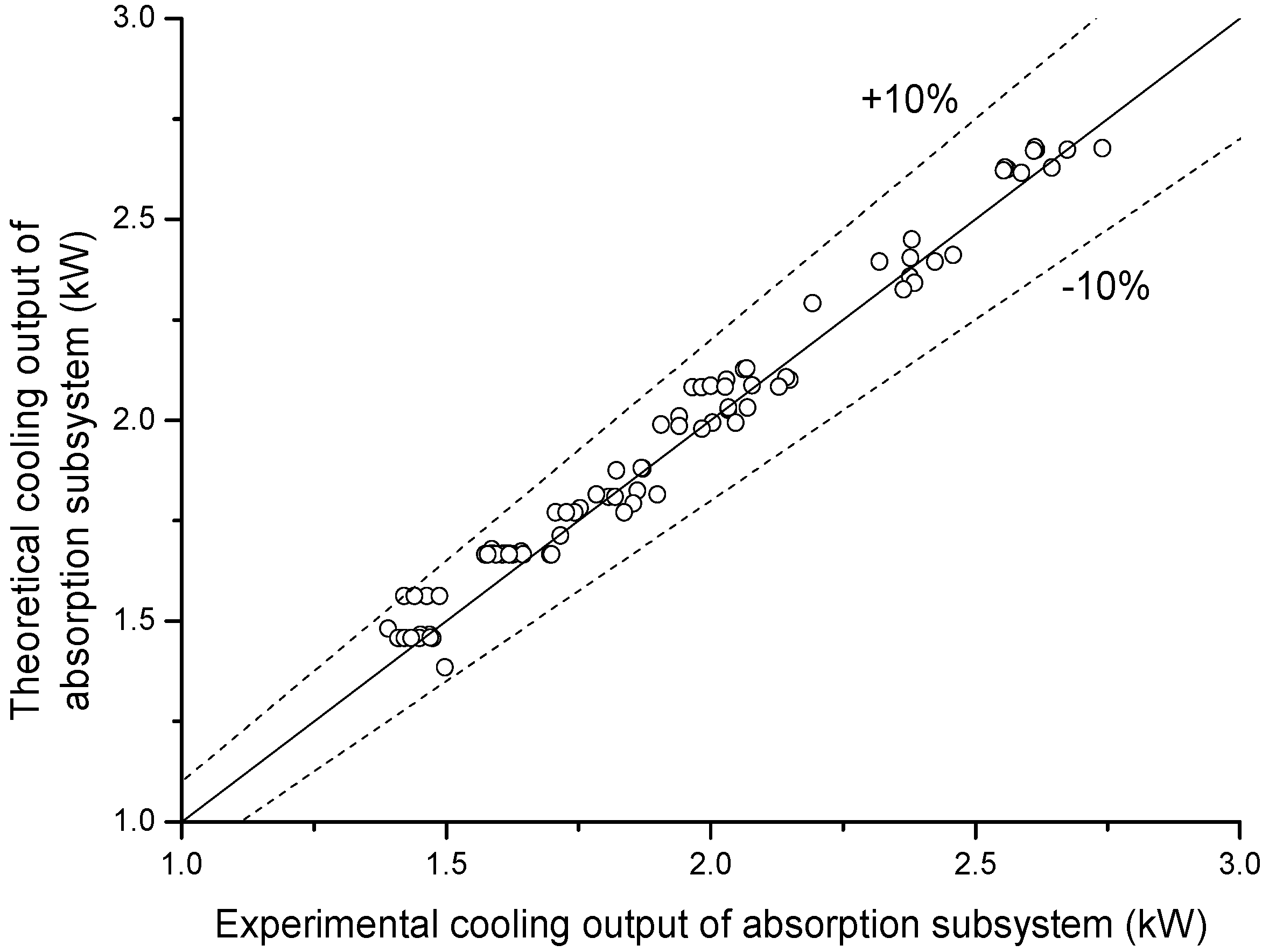
The compression subsystem is described by the lumped parameter method. Its condenser and evaporator are modeled by mass and energy conservations:
m h e , c s , i , i f = m h e , c s , o , i f
Q h e , c s = m h e , c s , i , i f h h e , c s , i , i f m h e , c s , o , i f h h e , c s , o , i f
Q h e , c s = m h e , c s , e f c p , h e , c s , e f Δ T h e , c s , e f
Q h e , c s = ( U A ) h e , c s L M T D h e , c s
The energy balance in the subcooler is controlled as follows:
m 11 ( h 11 h 12 ) = m 3 ( h 4 h 3 ) = ( U A ) s u b , c s L M T D s u b , c s = Q e , a s
Here, the subcooling power equals the cooling capacity of the absorption subsystem and is controlled by the absorption subsystem model.
The flow rate of the refrigerant in the compression subsystem is as follows:
m c s , i f = m 11 = η v ρ s u c V s v c n
The expression of the compressor work is derived as follows:
W = m c s , i f ( h d i s , s h s u c ) / η s
The dependence of volumetric efficiency and isentropic efficiency on the compressor speed is considered using the following formula [25]:
η v = η v , d [ d 1 + d 2 ( n n d ) + d 3 ( n n d ) 2 ]
η s = η s , d [ e 1 + e 2 ( n n d ) + e 3 ( n n d ) 2 ]
Here, d 1 , d 2 , d 3 , e 1 , e 2 , and e 3 for the scroll compressor are 0.693, 0.543, −0.236, 1.599, −1.06, and 0.461, respectively. Further, the volumetric efficiency and isentropic efficiency in the design condition are 0.9369 and 0.6996, respectively, from the operational data offered by the manufacturer.
In terms of the definition, the COP of the compression subsystem is evaluated:
C O P c s = Q e , c s / W
It should be noticed that the above-mentioned COP is also the COP of the hybrid system in respect that the subcooling power produced by the absorption chiller is considered.

4. Model Validation

The off-design model of the SASCHCS is solved by the FORTRAN program. The solving process is exhibited in Figure 3. As shown, the introduction of a characteristic equation simplifies the iteration significantly, i.e., the calculation of the absorption subsystem depends only on the iteration, instead of the four heat exchangers (generator, condenser, evaporator, and absorber). Accordingly, the solving time reduces to approximately 20 s and the model is converged for a wide range of operational conditions. The thermodynamic properties of water and R410A are calculated by the software Refprop9 [26]. The convergence is thought to be reached when the deviation is less than 0.01.
The off-design model of the SASCHCS is verified by the experimental data of the prototype. In general, the validation consists of three sections: (1) characteristic equation of absorption; (2) model of compression subsystem based on the lumped parameter method; and (3) modeling of the hybrid system by coupling the models of both subsystems. Because the model of the compression subsystem has been verified in our study previously [23], two experiments were performed to verify the absorption subsystem and hybrid system models. The first experiment is performed to control the hot water temperature by adjusting the water flow rate of the collector to change the cooling capacity of the absorption subsystem. The second experiment is performed in the steady condition to measure the heat load. It is noteworthy that the off-design experiment of the SASCHCS cannot be performed because the inverter of the water pump in the compression subsystem has not been installed.
The deviation between the simulation result and operational data with respect to the absorption subsystem is shown in Figure 4. The flow rate of hot water, cooling water and chilled water of the absorption subsystem during the experiment is the same as the design condition exhibited in Table 1. The inlet temperature of the hot water changes from 50 °C to 70 °C. The inlet temperature of the cooling water ranges from 30 °C to 32 °C. In addition, the temperature of the chilled water depends primarily on the cooling capacity of the absorption subsystem. The greater the cooling output, the lower the temperature of the chilled water becomes. The corresponding inlet temperature of the chilled water is approximately 16 °C to 30 °C. Each data of the experiment was measured in the steady condition. A good agreement was obtained. Most of the deviations are less than 10%.
The validation regarding the off-design model of the hybrid system is demonstrated in Table 3. The inlet temperature of the hot water is 56 °C. For the compression subsystem, its inlet temperatures for the cooling water and chilled water are 28 °C and 12.8 °C, respectively. The superheating temperature is 6.8 °C. The flow rate of the chilled water is 1.06 kg/s. The other parameters are identical to the conditions listed in Table 1. As shown, the deviation between the simulation result and experimental data is small. The maximum relative error is lower than 4%.

5. Results and Discussion

In this section, the thermodynamic performance of the prototype in the base condition and that in the off-design is analyzed. The simulation condition (includes the nominal flow rate of the external fluid and compressor speed) is identical to that listed in Table 1.

5.1. Performance in Base Condition

The state property of each point in the design condition is listed in Table 4. As shown, the absorption subsystem provides high-temperature cooling, in which its inlet and outlet temperatures of chilled water are 18.8 °C and 16.75 °C, respectively. We found that this high-temperature cooling capacity can be converted into a low-temperature cooling capacity by the subcooling; therefore, it can be employed to fulfill the requirement of the building’s cooling. Additionally, low-grade solar energy is utilized adequately owing to the improvement in the evaporator temperature in the absorption subsystem. The absorption subsystem operates efficiently when the inlet temperature of the hot water is only 70 °C. It is noteworthy that the chilled water temperature of the absorption subsystem in the prototype is less than that in our previous investigation [8]. This is attributed to the evaporator of the absorption subsystem and subcooler not being integrated in the prototype, thus leading to the additional exergy destruction in the subcooler. Nevertheless, the separated evaporator of the absorption subsystem and subcooler is convenient for the modularization of the absorption subsystem and compression subsystem, as well as for the development of the SASCHCS.
The performance of the system in the design condition is demonstrated in Figure 5. The heat loads of the generator, condenser and absorber in the absorption subsystem, subcooler, condenser, evaporator, and compressor of the compression subsystem are 4.16 kW, 2.71 kW, 3.96 kW, 2.52 kW, 16.89 kW, 16.21 kW, and 3.12 kW, respectively. As shown, the ratio of cooling in the absorption subsystem to that in the hybrid system is 0.155. This low value is attributed to the excessively high cooling capacity of the absorption chiller that not only lowers its performance but also frosts the subcooler [15]. Furthermore, it is found that the corresponding COP of the absorption and compression subsystem is 0.605 and 5.225, respectively.

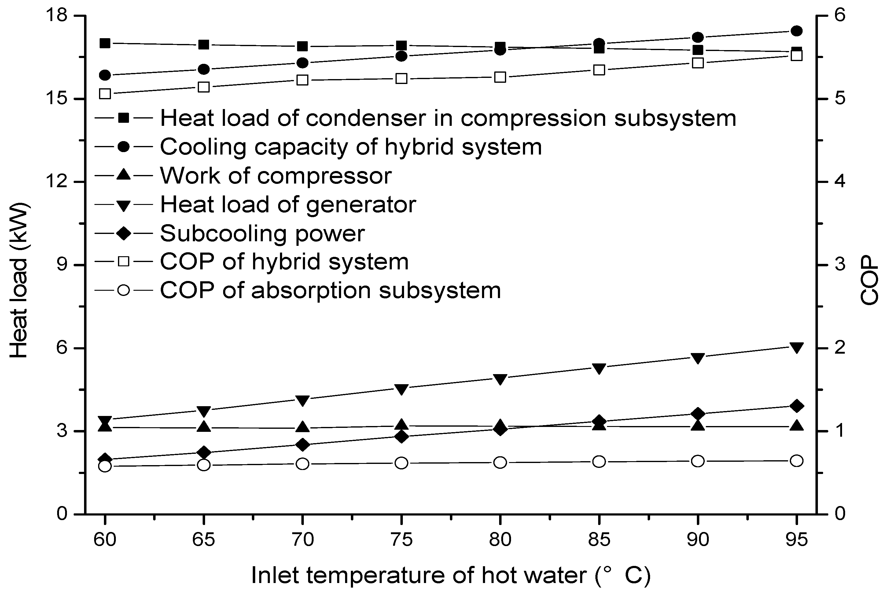
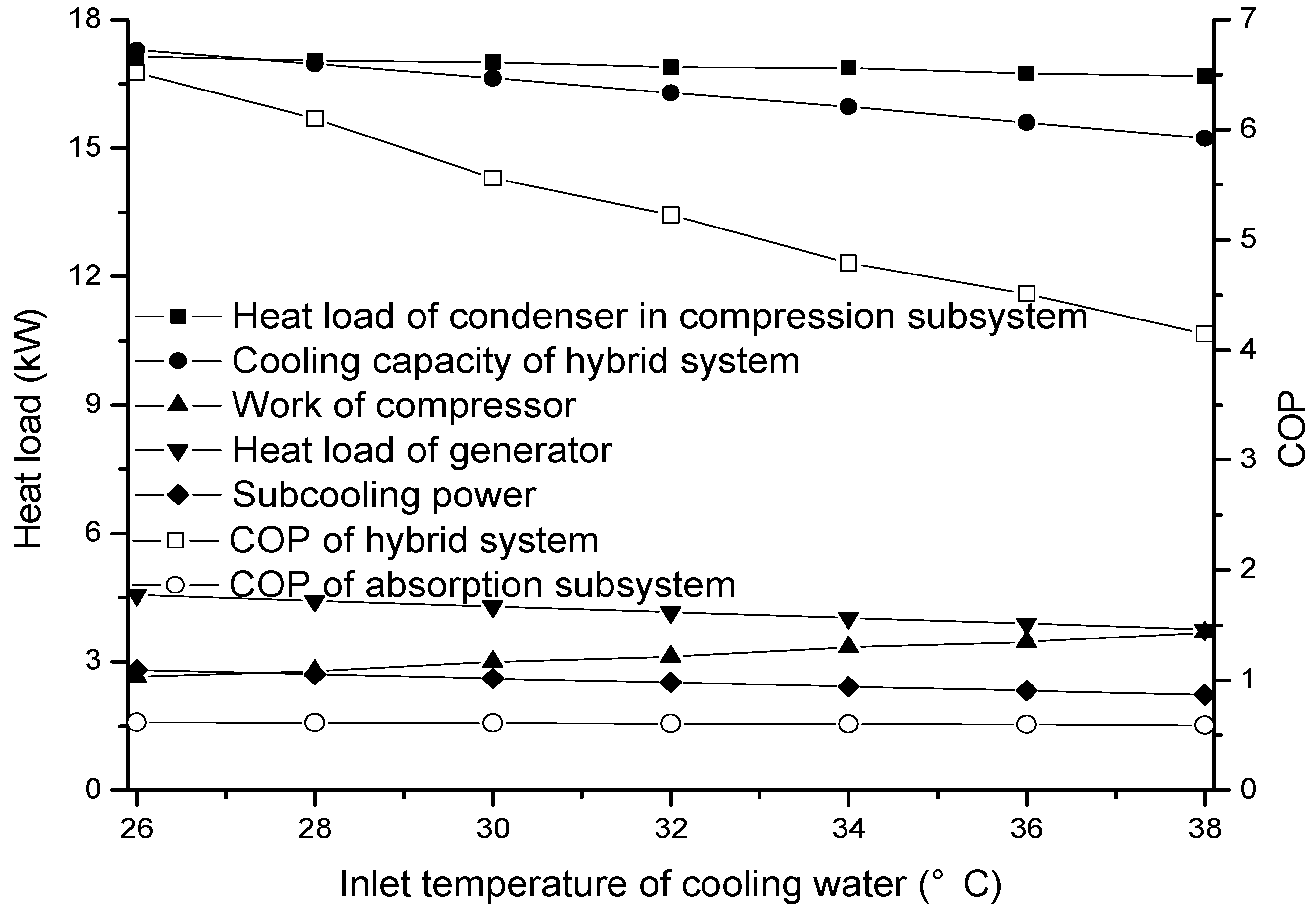
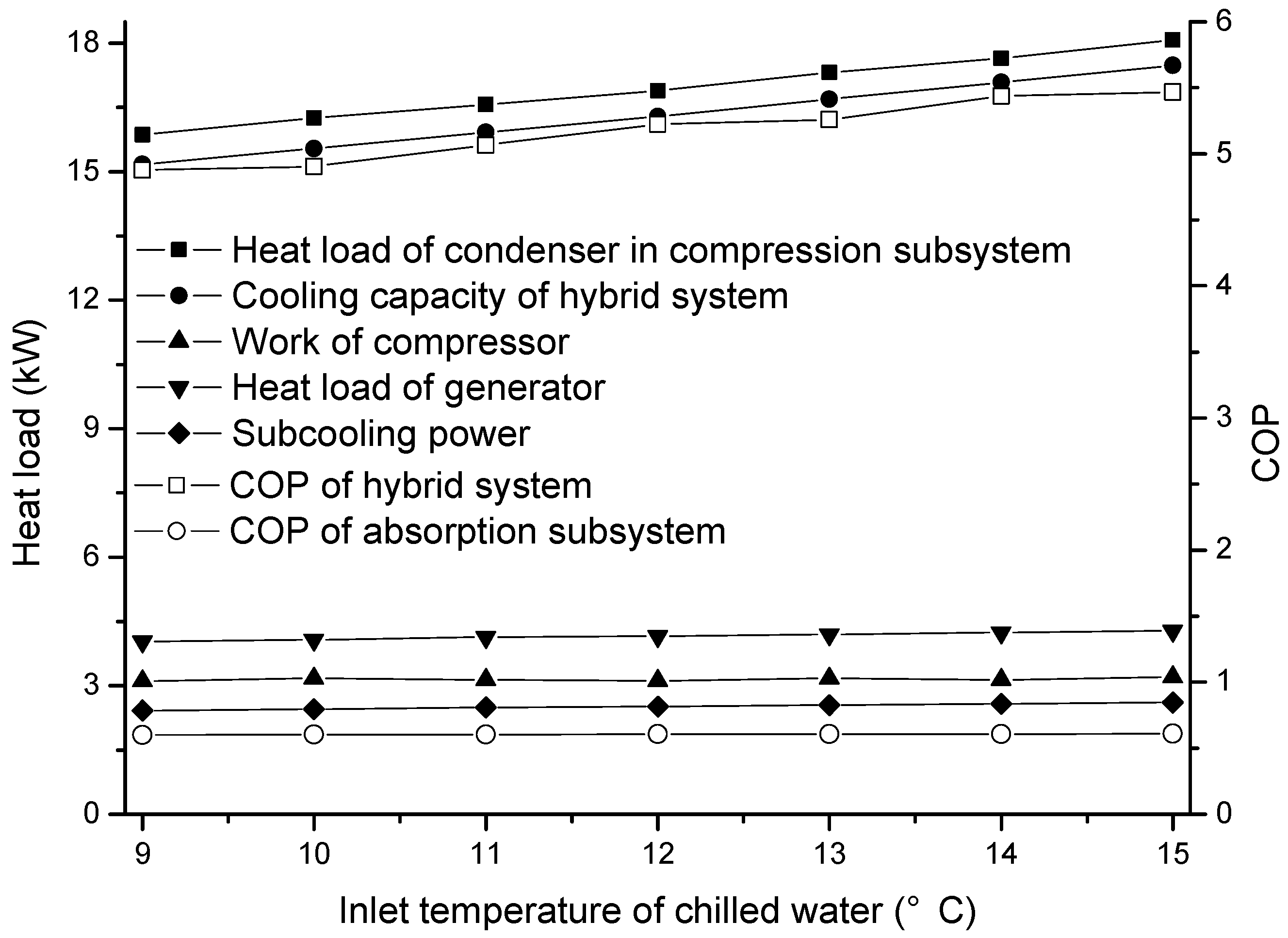
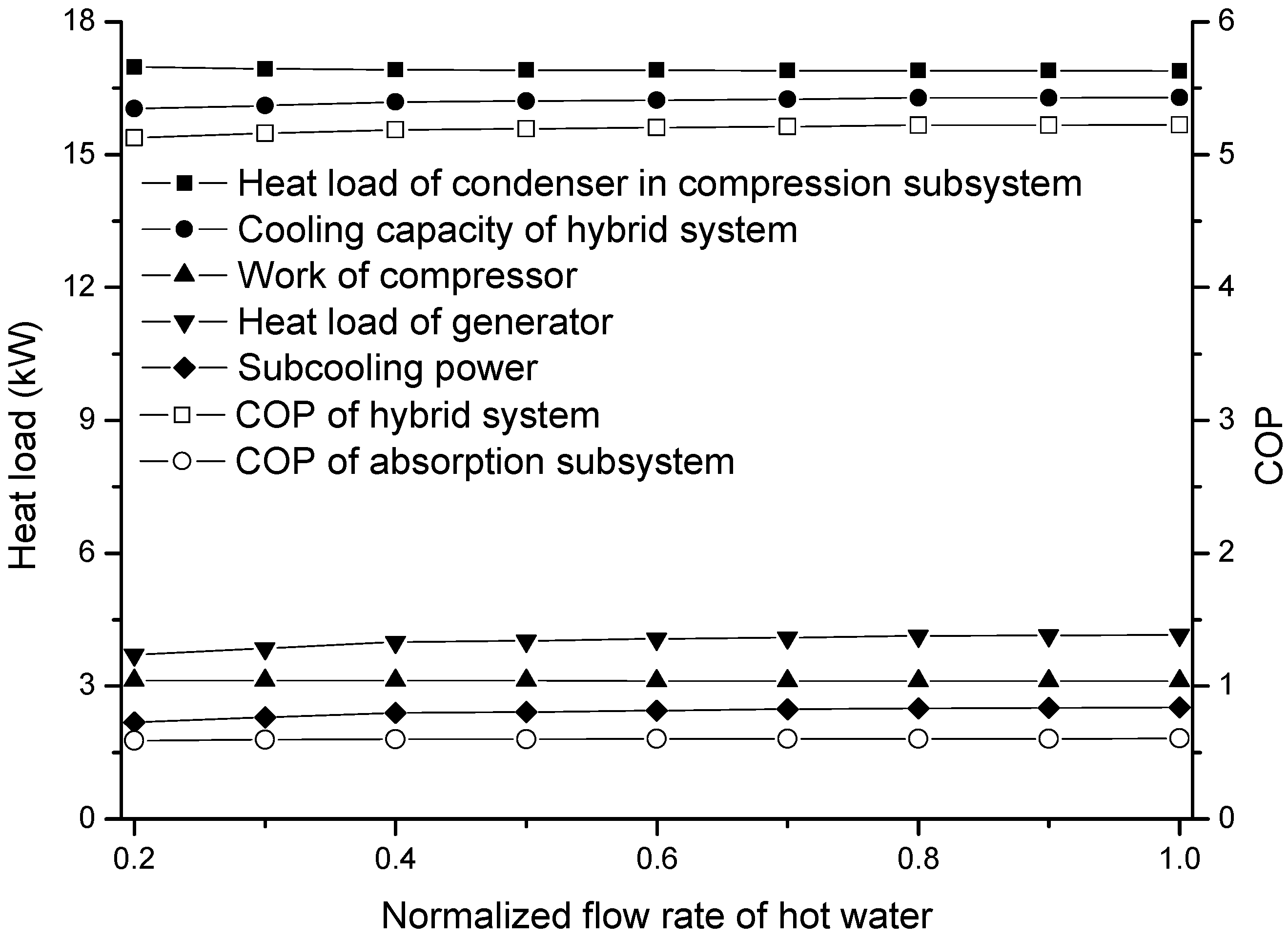
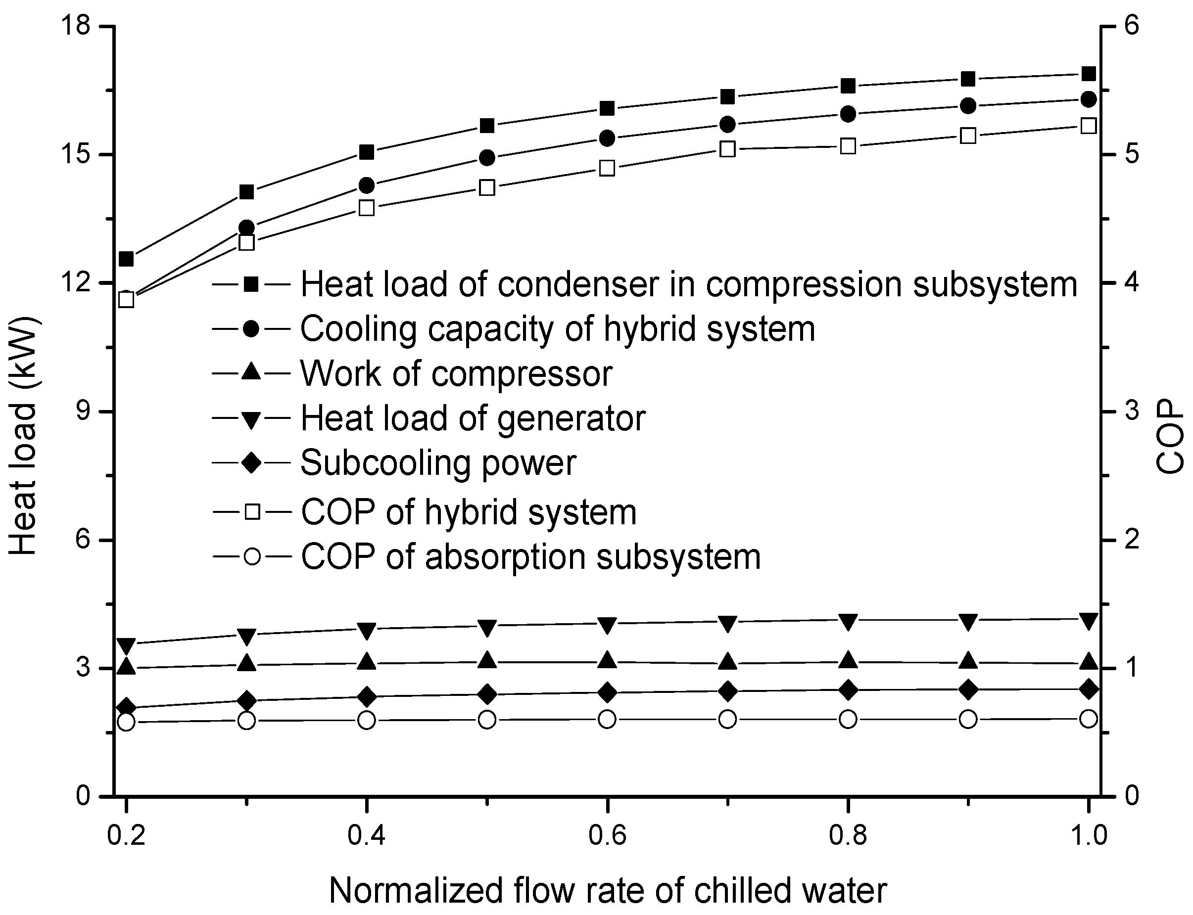
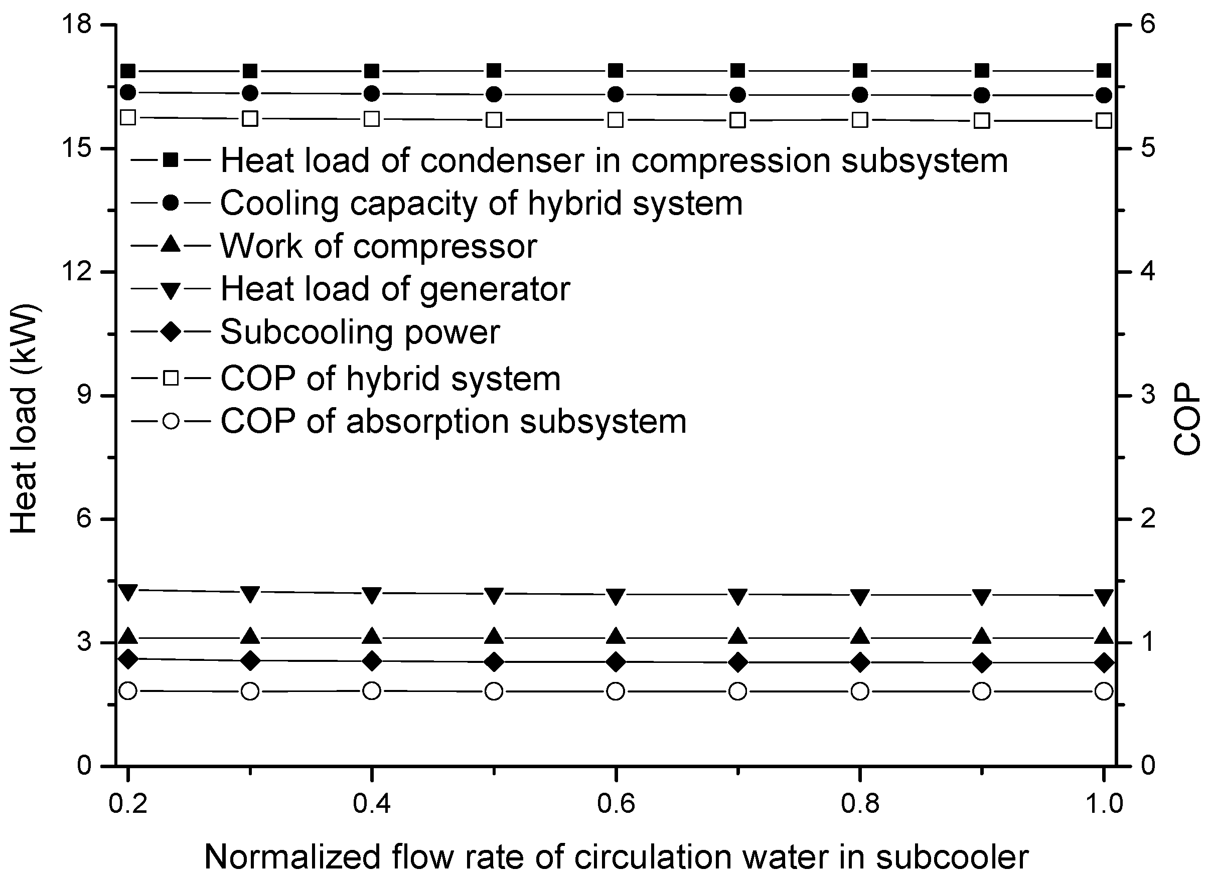
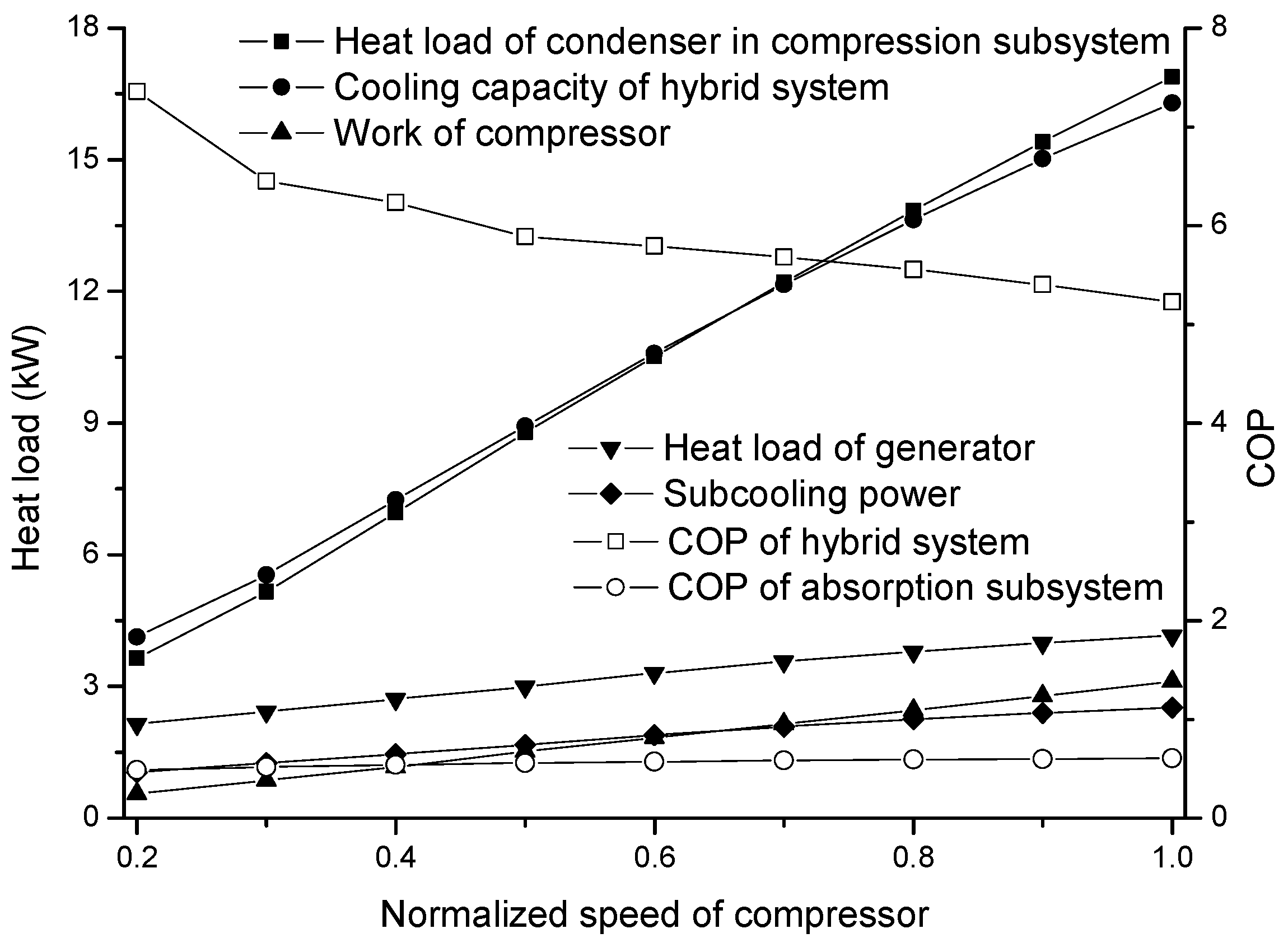
5.2. Off-Design Performance

The heat load and COP for different inlet temperatures of the hot water are exhibited in Figure 6. It is seen that the heat load of the generator and the cooling capacity of the absorption subsystem grow with the enhancement of the hot water temperature, owing to the rise of the generator temperature. Because the cooling output of the absorption subsystem serves as the subcooling power in the compression subsystem, the performance of the hybrid system also becomes better with the increase of inlet temperature in the hot water. The heat load of the generator and the cooling output of the absorption subsystem and hybrid system rises by 77.15%, 97.63% and 10.07%, respectively, when the inlet temperature of the hot water enhances by 35 °C. Meanwhile, the COP of the absorption and hybrid subsystem increases by 11.55% and 9.01%, respectively. Moreover, the heat load of the condenser in the compression subsystem and compressor work is insensitive to the change of the hot water temperature, which is similar to the trend of our previous study [23].
The heat load and COP for different inlet temperatures of the cooling water are shown in Figure 7. It is noteworthy that the cooling water of the absorber and two condensers are from the same cooling tower. Hence, the variation of cooling water temperature influences the above-mentioned three components and results in two opposite behaviors regarding the absorption subsystem. The improvement of the cooling water temperature in the condenser of the compression subsystem increases the chilled water temperature of the absorption subsystem, i.e., the inlet/outlet temperature of circulation water in the subcooler goes up from 9.48 °C/7.19 °C to 18.8 °C/16.75 °C when the inlet temperature of the cooling water rises from 26 °C to 32 °C, increasing the cooling capacity and COP of the absorption subsystem. However, the absorber temperature and condenser temperature in the absorption chiller enhances as well and leads to the deterioration of performance. It is seen that the performance of the absorption subsystem deteriorates with the rise of the cooling water temperature because the neglect influence is stronger. In addition, the compressor work goes up and the condenser heat load, cooling capacity, as well as the COP of the compression subsystem reduces with the rise of the cooling water temperature, as expected. The heat load of the generator, evaporator in the absorption subsystem, and the condenser and evaporator in the compression subsystem falls by 17.71%, 21.02%, 2.61% and 11.93%, respectively, and the work of the compressor grows by 38.65% when the inlet temperature of the cooling water rises by 12 °C. Simultaneously, the COP of the absorption and hybrid system drops by 4.02% and 36.48%, respectively.
The heat load and COP for the different inlet temperatures of the chilled water are shown in Figure 8. The increase in the inlet temperature in the chilled water increases the suction density of the compressor such that the flow rate of the refrigerant in the compression subsystem increases. It can be inferred that the subcooling of the compression subsystem decreases in this condition. In addition, the condenser temperature increases with the increasing chilled water temperature [27]. Therefore, the abovementioned effect increases the R410A temperature in the subcooler and the consequent improvement in the circulation water temperature of the subcooler. However, this increase of chilled water in the absorption subsystem is not notable, i.e., the inlet/outlet temperature of chilled water in the absorption subsystem enhances from 18.12 °C/16.14 °C to 19.44 °C/17.31 °C as the inlet temperature of the chilled water rises from 9 °C to 15 °C. Consequently, the heat load of the generator, cooling output and COP of the absorption subsystem just goes up by 6.33%, 7.72% and 1.31%, respectively, when the inlet temperature of the chilled water rises by 6 °C. Besides, the performance of the hybrid system benefits from the rise of the chilled water temperature. The heat load of the condenser in the compression subsystem, cooling capacity and COP of the hybrid system increases by 13.94%, 15.23% and 12.1%, respectively. For the compressor, the dependence of its consumption on the chilled water temperature is weak, owing to the decrease of the pressure ratio.
The heat load and COP for different flow rates of hot water are shown in Figure 9. The decline of flow rate in the hot water decreases the generator temperature and the performance of the absorption subsystem. The heat load of the generator, cooling capacity and COP of the absorption subsystem comes down by 10.87%, 13.11% and 2.52%, respectively when the flow rate of hot water reduces by 80%. It can be inferred that the effect of the flow rate in the hot water on the performance of the compression subsystem is weak due to the slight variation of the subcooling power. The cooling capacity and COP of the hybrid system goes down by 1.55% and 1.89%, respectively. Especially, the change of condenser heat load in the compression subsystem and the work of the compressor can be ignored.
The heat load and COP for different flow rates of cooling water in the compression subsystem are displayed in Figure 10. As shown, the condenser temperature increases and the evaporator temperature maintains nearly constant with the decrease in the flow rate in the cooling water for the vapor compression chiller [27]. The improvement of the condenser temperature in the compression subsystem increases the temperature of the circulating water in the subcooler, resulting in the performance improvement of the absorption subsystem. However, the above-mentioned advantage is offset by the high condenser temperature of the compression subsystem, and leads to the poor performance of the hybrid system. The heat load of the generator, cooling capacity and COP of the absorption subsystem increases by 35.13%, 42.47% and 5.43%, respectively, as the flow rate of the cooling water in the compression subsystem goes down by 80%. However, simultaneously, the heat load of the condenser in the compression subsystem, cooling out and COP of the hybrid system comes down by 5.81%, 6.74% and 32.44%, respectively, and the compressor work rises by 38.04%.
The heat load and COP for different flow rates of chilled water are shown in Figure 11. As shown, the evaporator and condenser temperatures decrease with the decrease in flow rate in the chilled water for the vapor compression chiller [27]. Therefore, it can be inferred that the performances of the absorption and compression subsystems deteriorate when the flow rate of the chilled water decreases. The heat load of the generator, cooling capacity and COP of the absorption subsystem lowers by 14.28%, 17.24% and 3.45%, respectively, when the flow rate of chilled water comes down by 80%. In addition, the heat load of the condenser in the compression subsystem, compressor work, cooling out and COP of the hybrid system falls by 25.62%, 3.56%, 28.55% and 25.91%, respectively. The insignificant variation of the compressor work is attributed to the relatively smaller change of the pressure ratio caused by the simultaneous decline of the evaporator and condenser pressure.
The off-design performance with the flow rate of circulation water in the subcooler is shown in Figure 12. The inlet and outlet temperature of the circulating water is strongly coupled with the corresponding flow rate. The less the flow rate is, the higher the temperature of the circulating water becomes. In addition, the multiplication of temperature difference and flow rate in the circulation water is nearly constant, i.e., the temperature difference goes up from 2.15 °C from 5.2 °C as the flow rate goes down by 40%. This trend means that the flow rate of the circulating water in the subcooler has a tiny effect on the performance of the absorption subsystem. Hence, the heat load of the component and COP in the hybrid system is thought to be independent of it as well.
The heat load and COP for different compressor speeds are exhibited in Figure 13. For the compression subsystem, because the heat load and cooling output decrease with the decrease in the compressor speed, the condenser temperature decreases and the evaporator temperature increases. Accordingly, this change is adverse to the operation of the absorption subsystem but favorable for the performance of the compression subsystem. The heat load of the generator, cooling capacity and COP of the absorption subsystem goes down by 48.52%, 58.6% and 19.58%, respectively, when the speed of the compressor lowers by 80%. In addition, the heat load of the condenser in the compression subsystem, the work of the compressor and the cooling output of hybrid system drops by 78.46%, 82.04% and 74.7%, respectively. The COP of the hybrid system goes up by 40.8%.

6. Conclusions

The off-design model of the SASCHCS that is exact and can be solved easily was built. It was based on the combination of the characteristic equation in the absorption subsystem and the lumped parameter model of the compression subsystem. The outstanding advantage of this model is the reduced solving time and reliable convergence as the operating condition deviates from the design condition significantly. A prototype and the corresponding experiment system were developed to verify the model. The maximum deviation of the theoretical result and experimental data was lower than 4%.
The off-design model of the hybrid system was employed to examine the performance in the variable conditions. The COP of the absorption subsystem goes up by 11.55%, 1.31% and 5.43% when the inlet temperatures of hot water and chilled water rise by 35 °C and 6 °C and the flow rate of cooling water in the compression subsystem falls by 80%, respectively. Besides, it is found that the COP of the absorption subsystem comes down by 4.02%, 2.52%, 3.45% and 19.58% as the cooling water temperature rises by 12 °C and the hot water flow rate, chilled water flow rate and compressor speed drop by 80%, respectively. For the compression subsystem, its COP enhances by 9.01%, 12.1% and 40.8% when the inlet temperatures of the hot water and chilled water increases by 35 °C and 6 °C and the compressor speed goes down by 80%, respectively. In addition, the COP of the compression subsystem decreases by 36.48%, 1.89%, 32.44% and 25.91% as the cooling water temperature rises by 12 °C and the flow rates of hot water, cooling water in the compression subsystem and chilled water come down by 80%, respectively. Particularly, the COP of the absorption and compression subsystems is independent of the flow rate of the circulation water in the subcooler.

Author Contributions

Z.L. contributed to the conceptualization, methodology and writing. J.Y. contributed to formal analysis. E.C. contributed to the validation. Y.J. contributed to the data curation.

Funding

This work is supported by: (1) National Natural Science Foundation of China under contract No. 51206056, (2) Natural Science Foundation of Guangdong Province under contract No. 2018A030313310, (3) Fundamental Research Funds for the Central Universities under contract No. 2017ZD023, (4) Key Laboratory of Efficient and Clean Energy Utilization of Guangdong Higher Education Institutes under contract No. KLB10004.

Conflicts of Interest

The authors declare no conflict of interest.

Nomenclature

COP
coefficient of performance
cp
specific heat (kJ/kg °C)
e
specific exergy (kJ/kg)
E
exergy (kW)
h
specific enthalpy (kJ/kg)
LMTD
logarithmic mean temperature difference
m
mass flow rate (kg/s)
n
speed of compressor (r/s)
Q
energy (kW)
T
temperature (°C)
ΔT
temperature difference (°C)
ΔΔT
double difference of temperature (°C)
UA
multiplication of heat transfer coefficient and area (W/°C)
V
volume per revolution (cm3/r)
W
work of the compressor (kW)
z
ratio of logarithmic mean temperature difference to arithmetic mean
Greek symbols
ρ
density (kg/m3)
η
efficiency
Subscripts
a
absorber
as
absorption subsystem
avg
average
c
condenser
chw
chilled water
cw
cooling water
d
design
dis
discharge
e
evaporator
ef
external fluid
f
fuel
g
generator, global
he
heat exchanger
hw
hot water
i
inlet
if
internal fluid
loss
loss
min
minimum
o
outlet
p
product
s
isentropic
sub
subcooler
suc
suction
v
volumetric

References

  1. Fong, K.F.; Lee, C.K. Towards net zero energy design for low-rise residential buildings in subtropical Hong Kong. Appl. Energy 2012, 93, 686–694. [Google Scholar] [CrossRef]
  2. Colmenar-Santos, A.; Vale-Vale, J.; Borge-Diez, D.; Requena-Perez, R. Solar thermal systems for high rise buildings with high consumption demand: Case study for a 5 star hotel in Sao Paulo, Brazil. Energy Build. 2014, 69, 481–489. [Google Scholar] [CrossRef]
  3. Perez-Lombard, L.; Ortiz, J.; Pout, C. A review on buildings energy consumption information. Energy Build. 2008, 40, 394–398. [Google Scholar] [CrossRef]
  4. Zhai, X.Q.; Wang, R.Z. A review for absorbtion and adsorbtion solar cooling systems in China. Renew. Sustain. Energy Rev. 2009, 13, 1523–1531. [Google Scholar] [CrossRef]
  5. Noro, M.; Lazzarin, R.M. Solar cooling between thermal and photovoltaic: An energy and economic comparative study in the Mediterranean conditions. Energy 2014, 73, 453–464. [Google Scholar] [CrossRef]
  6. Shirazi, A.; Taylor, R.A.; White, S.D.; Morrison, G.L. Transient simulation and parametric study of solar-assisted heating and cooling absorption systems: An energetic, economic and environmental (3E) assessment. Renew. Energy 2016, 86, 955–971. [Google Scholar] [CrossRef]
  7. Jain, V.; Sachdeva, G.; Kachhwaha, S.S. Energy, exergy, economic and environmental (4E) analyses based comparative performance study and optimization of vapor compression-absorption integrated refrigeration system. Energy 2015, 91, 816–832. [Google Scholar] [CrossRef]
  8. Li, Z.Y.; Jing, Y.; Liu, J.P. Thermodynamic study of a novel solar LiBr/H2O absorption chiller. Energy Build. 2016, 133, 565–576. [Google Scholar] [CrossRef]
  9. Qureshi, B.A.; Inam, M.; Antar, M.A.; Zubair, S.M. Experimental energetic analysis of a vapor compression refrigeration system with dedicated mechanical sub-cooling. Appl. Energy 2013, 102, 1035–1041. [Google Scholar] [CrossRef]
  10. Xu, Y.J.; Jiang, N.; Pan, F.; Wang, Q.; Gao, Z.L.; Chen, G.M. Comparative study on two low-grade heat driven absorption-compression refrigeration cycles based on energy, exergy, economic and environmental (4E) analyses. Energy Convers. Manag. 2017, 133, 535–547. [Google Scholar] [CrossRef]
  11. Jing, Y.; Li, Z.Y.; Liu, L.M.; Lu, S.Z. Exergoeconomic assessment of solar absorption and absorption-compression hybrid refrigeration in building cooling. Entropy 2018, 20, 130. [Google Scholar] [CrossRef]
  12. Infante Ferreira, C.; Kim, D.S. Techno-economic review of solar cooling technologies based on location-specific data. Int. J. Refrig. 2014, 39, 23–37. [Google Scholar] [CrossRef]
  13. Li, Z.Y.; Liu, L.M. Economic and environmental analysis of solar absorption-subcooled compression hybrid cooling system. Int. J. Sustain. Energy 2018. [Google Scholar] [CrossRef]
  14. Li, Z.Y.; Liu, L.M.; Jing, Y. Exergoeconomic analysis of solar absorption-subcooled compression hybrid cooling system. Energy Convers. Manag. 2017, 144, 205–216. [Google Scholar] [CrossRef]
  15. Jing, Y.; Li, Z.Y.; Liu, L.M.; Lu, S.Z.; Lv, S.L. Exergoeconomic-optimized design of a solar absorption-subcooled compression hybrid cooling system for use in low-rise buildings. Energy Convers. Manag. 2018, 165, 465–476. [Google Scholar] [CrossRef]
  16. Liu, L.M.; Li, Z.Y.; Jing, Y.; Lv, S.L. Energetic, economic and environmental design of cooling capacity for absorption subsystem in solar absorption-subcooled compression hybrid cooling system based on data of entire working period. Energy Convers. Manag. 2018, 167, 165–175. [Google Scholar] [CrossRef]
  17. Xu, Y.J.; Jiang, N.; Wang, Q.; Chen, G.M. Comparative study on the energy performance of two different absorption-compression refrigeration cycles driven by low-grade heat. Appl. Therm. Eng. 2016, 106, 33–41. [Google Scholar] [CrossRef]
  18. Joudi, K.A.; Lafta, A.H. Simulation of a simple absorption refrigeration system. Energy Convers. Manag. 2001, 42, 1575–1605. [Google Scholar] [CrossRef]
  19. Navarro-Esbri, J.; Ginestar, D.; Belman, J.M.; Milian, V.; Verdu, G. Application of a lumped model for predicting energy performance of a variable-speed vapour compression system. Appl. Therm. Eng. 2010, 30, 286–294. [Google Scholar] [CrossRef] [Green Version]
  20. Pratihar, A.K.; Kaushik, S.C.; Agarwal, R.S. Simulation of an ammonia–water compression–absorption refrigeration system for water chilling application. Int. J. Refrig. 2010, 33, 1386–1394. [Google Scholar] [CrossRef]
  21. Sarabia Escriva, E.J.; Lamas Sivila, E.V.; Soto Frances, V.M. Air conditioning production by a single effect absorption cooling machine directly coupled to a solar collector field. Application to Spanish climates. Sol. Energy 2011, 85, 2108–2121. [Google Scholar] [CrossRef] [Green Version]
  22. Martinze, J.C.; Martinze, P.J.; Bujedo, L.A. Development and experimental validation of a simulation model to reproduce the performance of a 17.6 kW LiBr–water absorption chiller. Renew. Energy 2016, 86, 473–482. [Google Scholar] [CrossRef]
  23. Li, Z.Y.; Chen, E.J.; Jing, Y.; Lv, S.L. Thermodynamic relationship of subcooling power and increase of cooling output in vapour compression chiller. Energy Convers. Manag. 2017, 149, 254–262. [Google Scholar] [CrossRef]
  24. Puig-Arnavat, M.; Lopez-Villada, J.; Bruno, J.C.; Coronas, A. Analysis and parameter identification for characteristic equations of single- and double-effect absorption chillers by means of multivariable regression. Int. J. Refrig. 2010, 33, 70–78. [Google Scholar] [CrossRef]
  25. Li, W. Simplified steady-state modeling for variable speed compressor. Appl. Therm. Eng. 2013, 50, 318–326. [Google Scholar] [CrossRef]
  26. Refprop9. Available online: http://www.nist.gov/srd/nist23.cfm (accessed on 15 August 2018).
  27. Herbas, T.B.; Berlinck, E.C.; Uriu, C.A.T.; Marques, R.P.; Parise, J.A.R. Steady-state simulation of vapour-compression heat pumps. Int. J. Energy Res. 1993, 17, 801–816. [Google Scholar] [CrossRef]
Figure 1. Picture of prototype.
Applsci 08 02612 g001
Figure 2. Schematics of prototype.
Applsci 08 02612 g002
Figure 3. Solving process of model.
Applsci 08 02612 g003
Figure 4. Model validation of absorption subsystem.
Applsci 08 02612 g004
Figure 5. Performance of hybrid system in the design condition.
Applsci 08 02612 g005
Figure 6. Performance with the inlet temperature of hot water.
Applsci 08 02612 g006
Figure 7. Performance with the inlet temperature of cooling water.
Applsci 08 02612 g007
Figure 8. Performance with the inlet temperature of chilled water.
Applsci 08 02612 g008
Figure 9. Performance with the flow rate of hot water.
Applsci 08 02612 g009
Figure 10. Performance with the flow rate of cooling water in the compression subsystem.
Applsci 08 02612 g010
Figure 11. Performance with the flow rate of chilled water.
Applsci 08 02612 g011
Figure 12. Performance with the flow rate of circulation water in subcooler.
Applsci 08 02612 g012
Figure 13. Performance with the speed of the compressor.
Applsci 08 02612 g013
Table 1. Condition of system.
ParameterBase ConditionRange
( U A ) g , a s ( kW / ° C )0.7347-
( U A ) a , a s ( kW / ° C )0.8224-
( U A ) c , a s ( kW / ° C )1.07-
( U A ) e , a s ( kW / ° C )1.2731-
( U A ) c , c s ( kW / ° C )4.1615-
( U A ) e , c s ( kW / ° C )3.468-
( U A ) s u b ( kW / ° C )0.2264-
V s u c ( cm 3 / r )88.4-
T h w , i (°C)7060–90
T c w , i (°C)3226–38
T c h w , c s , i (°C)129–15
n c o m (rpm)18000.2–1.0 (Normalized)
m h w ( kg / s )0.2780.2–1.0 (Normalized)
m c w , c , a s ( kg / s )0.25-
m c w , a , a s ( kg / s )0.222-
m c h w , a s ( kg / s )0.2920.2–1.0 (Normalized)
m c w , c s ( kg / s )0.9080.2–1.0 (Normalized)
m c h w , c s ( kg / s )0.7330.2–1.0 (Normalized)
Table 2. Specification of test equipment.
Test EquipmentAccuracy
Turbine flowmeter0.5% of the reading
T-type Thermocouple2.5% of the reading
Table 3. Model Validation of hybrid system.
ItemModelExperimentRelative Error
T c w , c s , o (°C)31.5332.73.58%
T c h w , c s , o (°C)10.09.91.01%
T d i s (°C)59.6859.40.47%
Δ T s u b (°C)14.2814.11.28%
Table 4. State property of each point in design condition.
Pointp (kPa)T (°C)Pointp (kPa)T (°C)
1100701010036.43
210066.44112340.938.66
310018.8122340.922.18
410016.7513909.364.16
51003214909.364.16
610036.25152340.961.16
7100321610012
810034.58171006.71
910032

