Article

Experimental Study and Parameter Optimization of a Magnetic Coupled Piezoelectric Energy Harvester

State Key Laboratory of Precision Measurement Technology and Instrument, Tianjin University, Tianjin 300072, China
*
Author to whom correspondence should be addressed.
Appl. Sci. 2018, 8(12), 2609; https://doi.org/10.3390/app8122609
Submission received: 12 November 2018 / Revised: 4 December 2018 / Accepted: 11 December 2018 / Published: 13 December 2018
(This article belongs to the Special Issue Piezoelectric Energy Harvesting: Materials, Devices and Application)

Abstract

:
Piezoelectric energy harvesting is a promising way to develop self-sufficient systems. Structural design and parameter optimization are key issues to improve the performance in applications. This paper presents a magnetic coupled piezoelectric energy harvester to increase the output and bandwidth. A lumped parameter model considering the static position is established and various modes are simulated. This paper focuses on the “Low frequency repulsion mode”, which is more practical. The experiment platform is built with the Macro Fiber Composite (MFC) material, and the results are consistent with the analytical simulation. The optimization process of some key parameters, such as magnets spacing and flux density, is carried out. The results show that there is a corresponding optimal spacing for each flux density, which is positive correlated. With the optimized parameter design, the system achieves peak electrical power of 3.28 mW under the harmonic excitation of 4 m/s2. Compared with the conventional single cantilever harvester, the operated bandwidth is increased by 66.7% and the peak output power is increased by 35.0% in experiment.

1. Introduction

In recent years, energy harvesting technology (EHT) has received extensive attention and promoted the development of self-sufficient systems. EHT can convert various energy sources in the environment into electrical energy, providing energy for wireless low power consumption devices [1]. This “no maintenance” mode will greatly decrease maintenance costs and battery disposal problems. In particular, ambient EHT brings revolutionary development to wireless sensor networks [2]. In addition to no maintenance, it also expands the deployment area for intelligent self-sufficient wireless sensor systems [3].
In numerous EHTs, vibration is a promising source with high power density [4]. As a common physical phenomenon, vibration is widely found in production and living environments such as home appliances, vehicles, natural environments [5], and buildings [6]. It also exists in life phenomena such as heartbeat [7] and limb activities [8]. At present, the commonly used electromechanical conversion methods include piezoelectric method [9,10], electromagnetic method [11], electrostatic method [12], magnetostrictive method [13], etc. Among them, the piezoelectric method based on cantilever structure has gained great attention due to its high energy conversion efficiency and simple processing design [14,15].
However, the cantilever beam vibration energy harvester has some obvious obstacles for extensive applications. When the resonance frequency band of the cantilever beam is not matched with the excitation frequency, the electromechanical conversion efficiency is significantly reduced. For the application level, there is almost no single-frequency stable excitation source in real life. Reilly et al. [16] analyzed some common vibration sources, and it can be seen that the vibration sources of complex machines are generally broadband. Thus, the conventional single cantilever beam harvester requires performance improvement for applications.
At present, researchers have considered the complexity of the actual excitation source, and proposed some optimization schemes to increase the amplitude or the bandwidth [17]. The methods can be classified according to linear and nonlinear principles.
Among the linear optimization methods, a plurality of resonance frequencies are generated in the form of array or multi degrees of freedom. The array method utilizes a plurality of individual cantilever beams, which is simple to design. However, the volume and matching circuit of the system are relatively large [18]. The multi degrees of freedom method is relatively complex but more robust, and generally establishes double or more degrees of freedom in a composite form. The system, due to the coupling between multi modalities, reduces the individual response amplitude for each degree of freedom [19].
The nonlinear optimization methods mainly utilize various auxiliary structures to introduce nonlinear stiffness. One of the representative methods is the ‘Stop Blocking Method’ in Figure 1a, which introduces piecewise stiffness for the system [20,21,22]. This method broadens the band at the expense of decreasing the peak value, and requires that the vibration amplitude is greater than the stopper spacing, which does not work in a small vibration environment.
Another representative method is the ‘Multi-Stable Method’, and the nonlinear stiffness is introduced by magnetic force to generate various steady states [23,24]. Higher amplitude is generated across multiple potential wells. One common structure utilizes two axially opposite magnets to build the bistable system [25,26], as shown in Figure 1b. The structure has a large operating frequency range and amplitude. However, more precise design and processing are required for the multi-stable method, and small amplitude or fast changing excitation is not suitable.
Another nonlinear method, called the ‘Vertical Magnetic Method’, utilizes vertical auxiliary magnets. This method was proposed earlier by Challa et al. [27,28], as shown in Figure 1c. He set up two fixed auxiliary magnets, and adjusted the system resonance frequency between 22 and 32 Hz by adjusting the spacing. Zhang et al. [29,30] studied the resonant response of a single fixed auxiliary magnet structure using a three-time scale method, and found that the structure has a certain effect of widening the frequency band. Firoozy et al. [31] established a distributed reduced-order model based on the Galerkin method, taking into account the angle between the magnets during motion.
Tang et al. [32] installed the auxiliary magnet on the other cantilever beam parallel, and published a letter which compared the structure with the fixed auxiliary magnet preliminarily. Tang established a lumped parameter model for the nonlinear piezomagnetoelastic harvester. Abdelkefi et al. [33] established a distributed parameter model, which was compared with Tang’s lumped parameter model, but still mainly discussed the fixed magnet structure, and did not further analyze the structure of Tang. Yuan et al. [34] applied the harmonic balance method with alternating frequency/time domain progress to predict steady-state responses of nonlinear piezoelectric mechanical systems, and Tang’s model was used as an example to verify the feasibility of the algorithm. The research to date has not analyzed the parameter optimization or properties of the structure.
In this paper, the performance of a magnetic coupled piezoelectric energy harvester is analyzed in detail through experiments and simulations. For analysis and parameter optimization, a theoretical lumped parameter model is established. Compared with Tang’s model [32], the model of this paper considers more details. Based on simulation and experiment, different parameter configurations are discussed. The parameters are optimized and the optimized results are tested experimentally. The results show that the magnetic coupled piezoelectric energy harvester can effectively improve the performance of the conventional harvester and has better practical potential. The paper is organized as follows: The operation principle and model are described in Section 2. The experiment setup is introduced in Section 3. In Section 4, the results and discussion are presented. The conclusion is in Section 5.

2. Modeling and Analysis

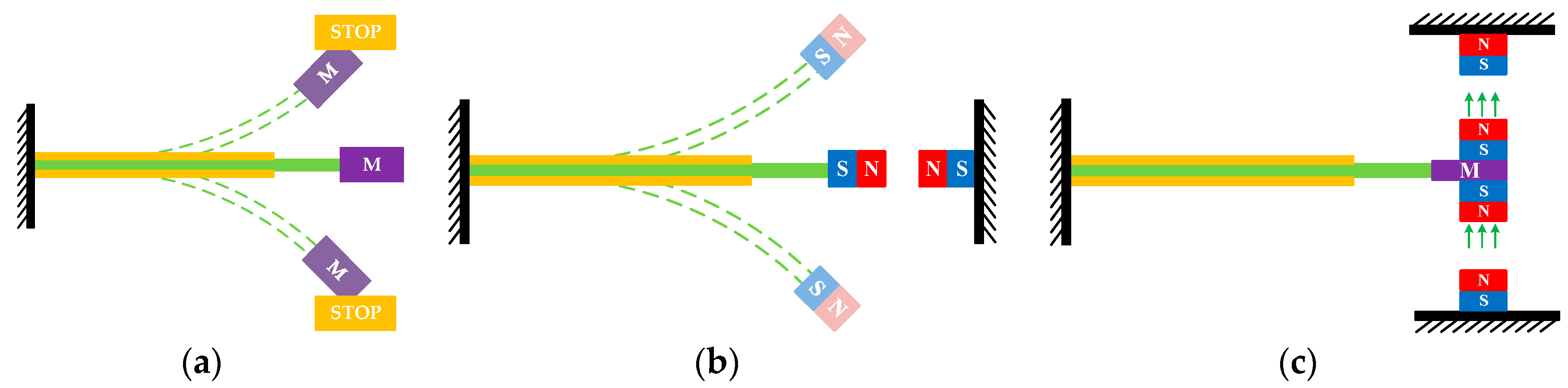
2.1. Operation Principle
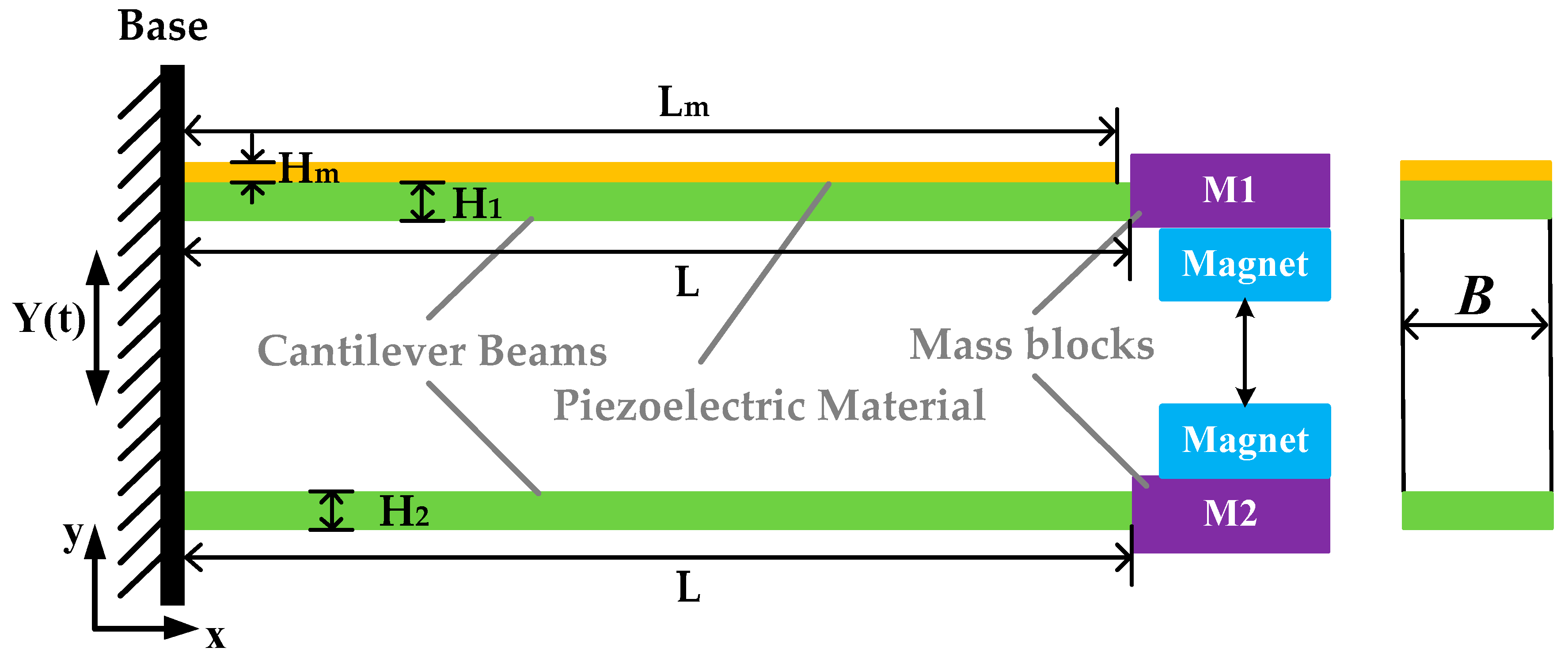
The magnetic coupled piezoelectric energy harvester studied in this paper is shown in Figure 2 and some parameters are marked in the figure. The structure consists of one unimorph cantilever beam and one auxiliary beam without piezoelectric material. The cantilever beams are fixed on a base parallel and the auxiliary beam is set below. The ends of the two cantilever beams are attached with the same type of magnets, which are aligned to introduce a vertical nonlinear magnetic force on the tips.
The resonance frequencies of the beams in the structure are different and determined by the material, size and mass parameters. In order to ensure the alignment of the magnets and facilitate the analysis, the length and width of the beams are the same and the frequency separation is performed by setting the mass and the height of the beams.

2.2. Modeling

In order to facilitate the analysis of structural characteristics, the modeling process is described in detail below. The main body of the structure is still a conventional cantilever and adds coupling of the magnetic field. The amplitude and bandwidth characteristics of the first-order response of the system dynamics are focused in this paper. The lumped parameter model can be established and calculated rapidly, and the first-order dynamic response can be accurately predicted under the action of the compensation factor [35]. Therefore, this paper plans to select the lumped parameter method for modeling. Different from Tang’s model [32], a more precise model is established that considers the influence of the static position of the magnets.
Some of the parameters used in the modeling process are listed in Table 1 and marked in Figure 2. For ease of description, the lower corner 1 represents the piezoelectric cantilever beam, the lower corner 2 represents the auxiliary cantilever beam and the lower corner p represents the piezoelectric material.
The electromechanically coupled lumped-parameter model of the linear cantilever energy harvester is expressed as [36]:
M z ( t ) + C z ( t ) + K z ( t ) + Θ V p ( t ) = μ M z 0 ( t ) C p V p ( t ) Θ z ( t ) = V p ( t ) / R } ,
where z(t) is the relative displacement of the mass and z0(t) is the base motion.
The directions of the dipoles are assumed as always vertically aligned. After introducing nonlinear magnetic force, a two-degree-of-freedom nonlinear piezoelectric dynamic model can be obtained:
M 1 z 1 ( t ) + C 1 z 1 ( t ) + K 1 z 1 ( t ) + Θ V p ( t ) + Q F m a g ( t ) = μ 1 M 1 z 0 ( t ) M 2 z 2 ( t ) + C 2 z 2 ( t ) + K 2 z 2 ( t ) Q F m a g ( t ) = μ 2 M 2 z 0 ( t ) C p V p ( t ) Θ z 1 ( t ) + V p ( t ) / R = 0 } ,
where Q is the system factor, Q = 1 when the beams are attracted, and Q = −1 when repulsed. The parameters in the equation are analyzed in detail below, taking into account the influence of piezoelectric materials, static position and other influencing factors.
To include the complete contribution of the piezoelectric layer in the system dynamics, the effect of the mass and the inertia of the piezoelectric layer are considered in the proposed model. The equivalent mass and stiffness of the two beams can be expressed as:
M 1 = 33 140 ( m p + ρ B L H 1 ) + m 1 + m m a g ; M 2 = 33 140 ρ B L H 2 + m 2 + m m a g ,
K 1 = 3 E 1 I 1 L 3 ; K 2 = 3 E I 2 L 3 .
μ is the correction factor of lumped parameter forcing function [35]. Θ can be obtained by short circuit current method [32]. C can be obtained by logarithmic decay method or viscous damping simplified empirical estimation method.
Two flat cylindrical magnets of the same size are used on the tip of the beams. To approximate the magnetic force, the force is assumed as a dipole-dipole interaction and the directions of the dipoles are assumed as always vertically aligned. Based on these assumptions, the approximate magnetic force is simplified [37]:
F m a g ( d ) = 6 π B r 2 r 4 h 2 μ a i r d 4 .
Suppose d0 is the static spacing of the magnets, Δd(t) = z1(t) − z2(t) is the change of the spacing over time, and the magnetic force is expressed as follows:
F m a g ( t ) = 6 π B r 2 r 4 h 2 μ a i r ( Δ d ( t ) + d 0 ) 4 .
The d0 is different from the spacing of the fixed ends D, and the analysis for d0 will be expanded below. The tip deflection of the cantilever beam is affected by the gravity of the beam itself and the concentrated mass of the tips. Therefore, based on the superposition theorem, the deflection equations of the two beams can be established as:
E 1 I 1 w 1 ( x ) = ( m 1 g + m m a g F m a g ) ( L x ) + m p g + ρ B L H 1 g 2 L x 2 ,
E I 2 w 2 ( x ) = ( m 2 g + m m a g + F m a g ) ( L x ) + ρ B L H 2 g 2 L x 2 .
Since the length Lp of the piezoelectric material is very close to the length L of the cantilever beam, it is assumed that the two parameters are equal in the modeling process. The elastic modulus of the piezoelectric composite beam is:
E 1 = H 1 E + H p E p H 1 + H p .
The calculation of the moment of inertia requires firstly determining the position of the neutral plane which is shown as:
H m = 0.5 H 1 2 + n ( H 1 + 0.5 H p ) H p H 1 + n H p ,
where n = Ep/E is the ratio of the modulus. The moment of inertia is:
I 1 = 1 12 W H 1 3 + W H 1 ( H m 0.5 h 1 ) 2 + n 12 W H p 3 + n W H p ( H 1 H m + 0.5 H p ) 2 .
The deflection static equation can be obtained by solving Equations (7) and (8) with the boundary condition (12), and the end deflection expression can be obtained.
w 1 ( 0 ) = 0 ; w 1 ( 0 ) = 0 ; w 2 ( 0 ) = 0 ; w 2 ( 0 ) = 0 .
The static magnetic force can be expressed as:
F m a g = 6 π B r 2 r 4 h 2 μ a i r 1 ( D w 1 ( L ) + w 2 ( L ) 2 h ) 4 .
Equation (13) is solved jointly with the end deflection equations of the two beams to obtain the static deflection w1(L) and w2(L). Therefore, the dynamic magnetic force expression is:
F m a g ( t ) = 6 π B r 2 r 4 h 2 μ a i r 1 ( Δ d ( t ) + D w 1 ( L ) + w 2 ( L ) 2 h ) 4 .
So far, the lumped parameter model of the magnetic coupled piezoelectric energy harvester has been established. Using the ode45 solver of MathWorks’ Matlab software, the Runge-Kutta algorithm can be used to solve the ordinary differential equation of Equation (2) numerically, and the output voltages at different excitation frequencies can be obtained under simulation conditions.

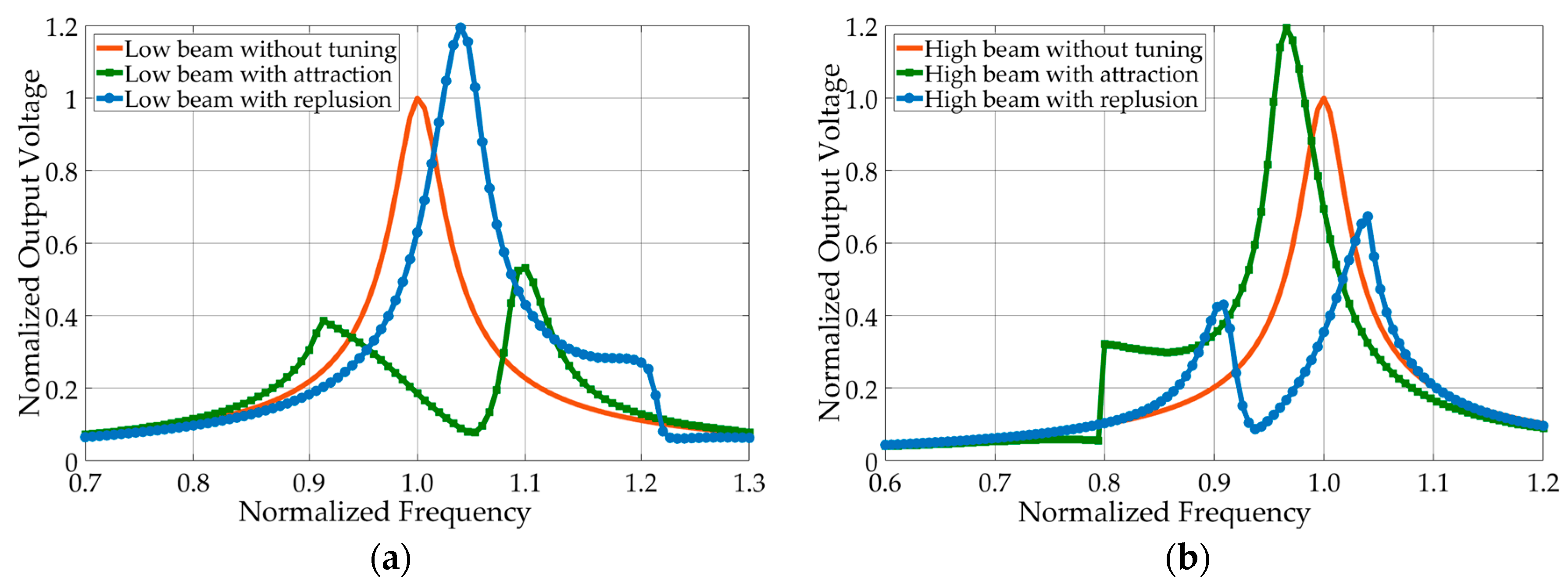
2.3. Simulation Analysis of Different Modes

This section will conduct a preliminary study of the different classifications of the structure based on the lumped parameter model. The nonlinear harvester with magnetic oscillator can be classified into two types according to attraction and repulsion, and two types according to the piezoelectric beam as a higher frequency beam or a lower frequency beam. Therefore, there are four different modes of structure named low/high beam with attraction/repulsion. The normalized simulation results are shown in Figure 3.
From the results of Figure 3, the hardening property is exhibited at the configuration of repulsion, and the system frequency band is shifted to the high frequency. Conversely, the softening characteristic appears at the configuration of attraction, and the system frequency band moves toward the low frequency. “Low beam repulsion mode” and “High beam attraction mode” exhibit high peak performance and widen a certain frequency band in the direction of frequency band shift. “Low beam attraction mode” and “High beam repulsion mode” exhibit a double degree-of-freedom feature. The specific results are evaluated as summarized in Table 2.
In the subsequent study of this paper, “Low beam repulsion mode” will be analyzed in detail for the following reasons:
  • The magnitude of the magnetic force is inversely proportional to the fourth power of the distance. The magnets at close distances are easy to fit at the attraction configuration, and cannot be automatically separated. This causes difficulties in actual assembly and application. Therefore, the repulsion mode is selected for analysis.
  • The energy is proportional to the square of the amplitude. Compared with the double degree-of-freedom characteristic, the high performance is more efficient in practical applications. Thus, “Low beam repulsion mode” is selected with higher amplitude and bandwidth than the conventional configuration without tuning.

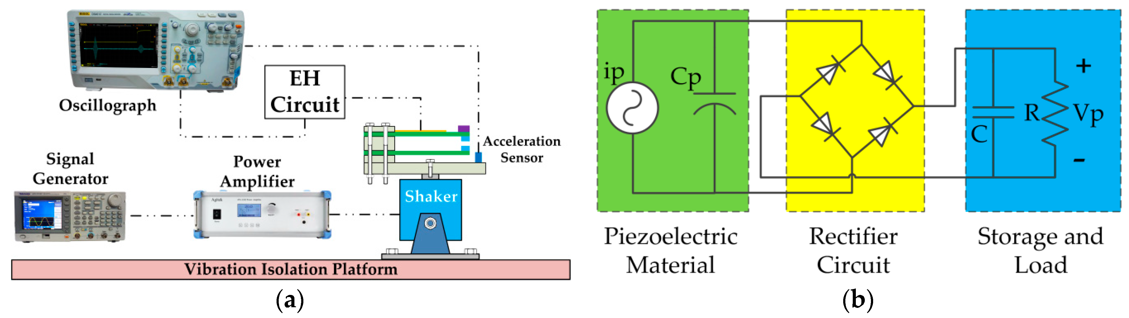
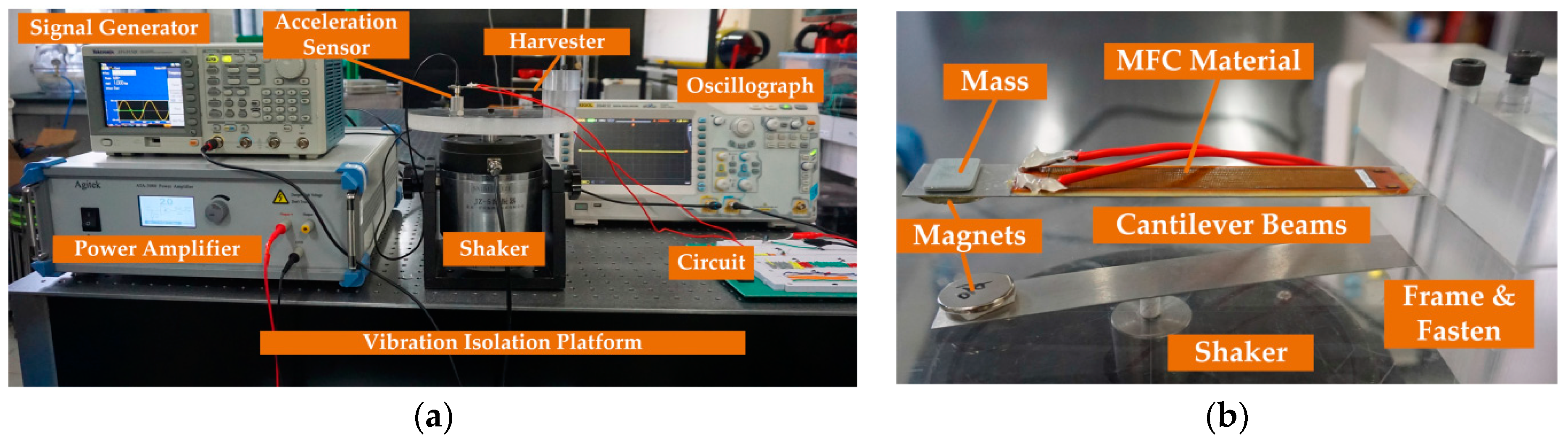
3. Experimental Platform Setup

In order to verify the lumped parameter model for the magnetic coupled piezoelectric energy harvester and investigate its characteristics, a corresponding experimental platform is designed. The experimental platform setup is presented is Figure 4. The experimental setup consists of an electromagnetic shaker (YE-5, Yiyang, Beijing, China), a signal generator (AFG3152C, Tektronix, Beaverton, OR, USA) to produce a range of vibration frequencies and a high-power amplifier (ATA-3080, Agitek, Xi’an, China) to create a cyclic force of the required magnitude. An acceleration sensor (AD100T, X&K, Hebei, China) is fixed on the base to measure the acceleration. The electrode of the piezoelectric material is connected with a rectifier bridge energy harvesting circuit, as shown in Figure 4b, and the load output voltage is observed through an oscilloscope (DS4012, Rigol, Beijing, China). At the same time, the oscilloscope also observes the vibration acceleration to ensure that the excitation amplitude is maintained the same at different frequencies.
The experiment prototype is shown in Figure 5. The devised harvester prototype consists of two cantilever beams with magnets, a proof mass and a base frame. Since the lumped parameter model is used in this paper, a mass must be added at the tip of the beam to ensure the accuracy of the model for frequency prediction [35]. The auxiliary beam uses a magnet as a mass and no other masses are installed. In order to make the piezoelectric beam have a lower resonance frequency, its thickness is designed to be thinner and an additional mass is added. The mass is composed of aluminum, because aluminum has no magnetic properties and does not affect the distribution of the magnetic field.
The piezoelectric cantilever beam is manufactured using aluminum alloy material (6061T) and commercially available piezoelectric material composed of macro fiber composite (MFC-M8514-P2, Smart Material Corp, Sarasota, FL, USA). The MFC is glued to the beam with epoxy adhesive (DP460, 3M, St. Paul, MN, USA). The magnets (Nd–Fe–B) are attached to the beam, which is easy for replacement during the experiment. The experimental frame is made of acrylic material and its spacing adjustment can be carried out by changing the intermediate block. Some parameters of the devised harvester are identified as shown in Table 3.

4. Results and Discussion

4.1. Experimental Results

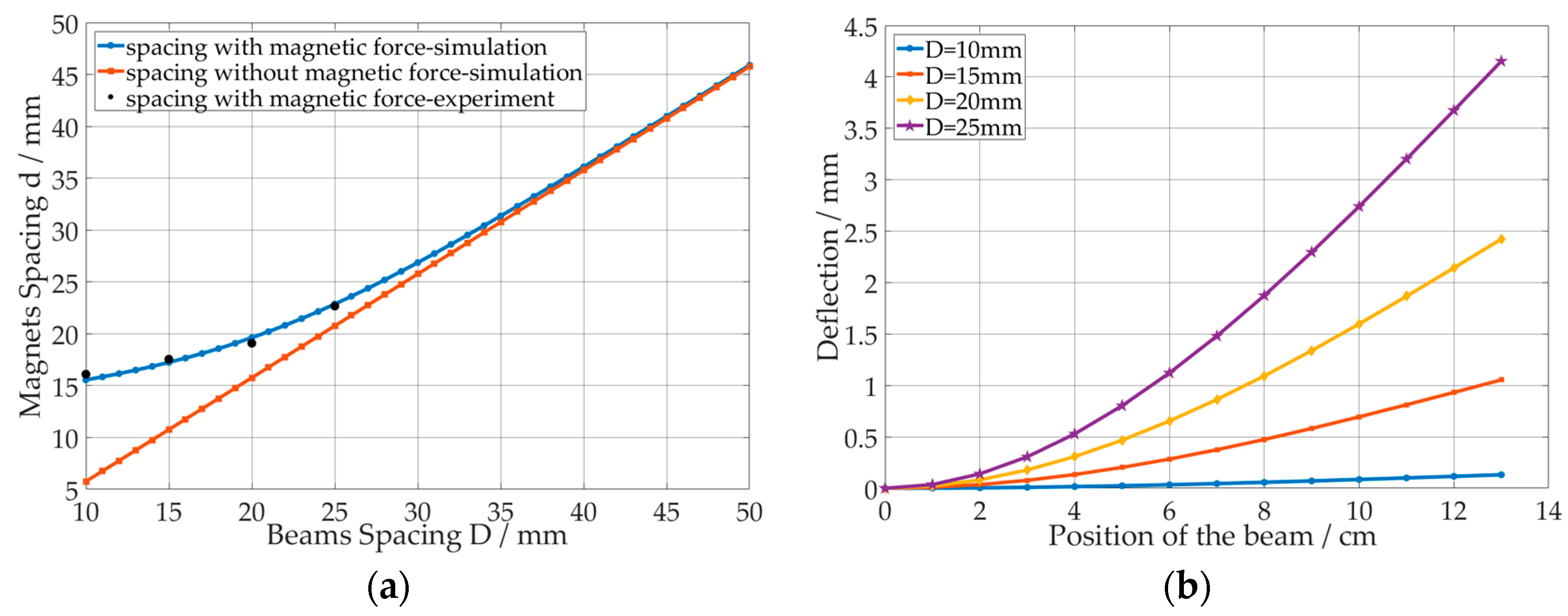
4.1.1. Static Analysis

First, the static state is analyzed with Br = 0.09 T and D = 10–50 mm. Figure 6a shows the magnets spacing curve as beams spacing changes. As the spacing D increases, the magnetic force drops rapidly, and the simulation results with or without magnets become very close. Therefore, the study is mainly carried out in the range of 10–25 mm, and the magnetic force is obvious in this range. The results of four experiments (10, 15, 20, 25 mm) show that the model can effectively predict the magnets spacing with an error of less than 4%. Figure 6b shows the static shape at different spacing based on the simulation. It can be more clearly seen from the figure that as the spacing D increases, the magnetic force and deflection decrease.

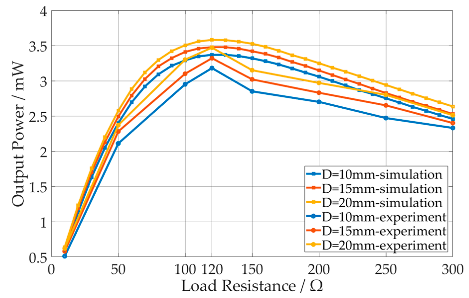
4.1.2. Load Resistance Analysis

In this section, the optimal load resistance is analyzed with the acceleration a = 4 m/s2 and the beams spacing D = 10, 15, 20 mm as an example. The effect of changing load resistance on output power is investigated in Figure 7; it has been verified that this optimum resistance is valid for the frequency range by simulation and experiment. With an increasing load resistance, the output power reaches an optimal point and then drops down. Experiments and simulations have the same trend. Through the impedance sweep, it can be seen that the maximum output power is reached near 120 kΩ at different spacing. Therefore, 120 kΩ is used as the experimental load resistance later.

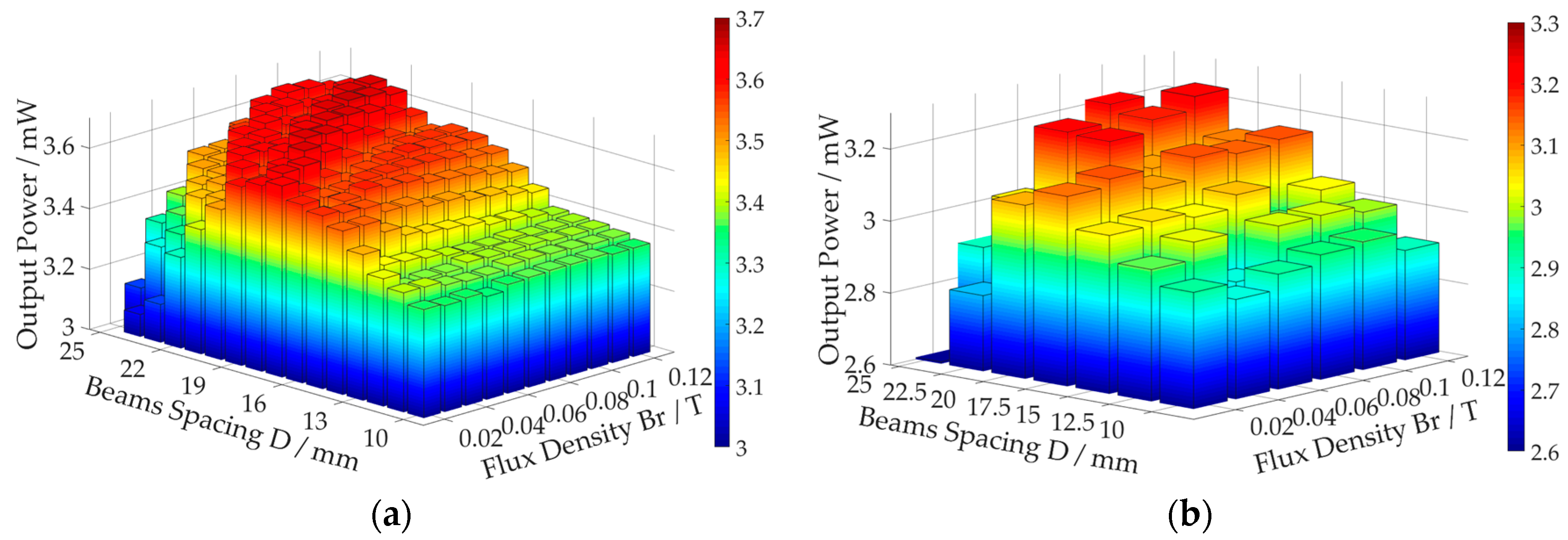
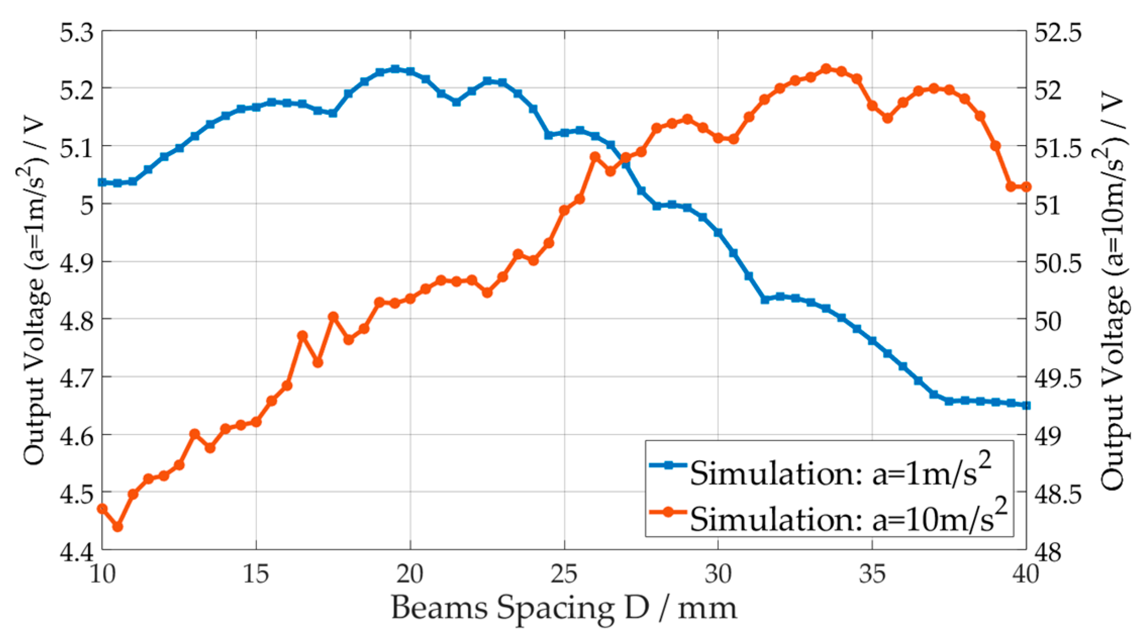
4.1.3. Key Parameters Analysis

In this section, the key nonlinear parameters that affect the harvesting efficiency will be analyzed. The main feature of the magnetic coupled piezoelectric energy harvester is the introduction of vertical nonlinear magnetic forces. It can be seen from Equation (5) that the magnet flux density Br and the magnets spacing d (affected by beams spacing D) directly affect the magnitude of the magnetic force and are the key parameters in the structural design. In the following, we will explore whether there is an optimum value of Br and D within a certain range through simulation and experiment.
Figure 8 shows the output power maximum of the energy harvester at different beams spacing D (10–25 mm) and different magnet flux density Br (0.02–0.12 T). Figure 8a is based on simulation, scanning at intervals of 1 mm and 0.01 T. Limited to the experimental conditions, only parts of the simulation parameters are tested. The results of the experiment are shown in Figure 8b with intervals of 2.5 mm and 0.02 T. It can be seen from the results that:
  • An optimal spacing D for each Br exists.
  • As Br increases, the optimal spacing increases.
  • The values of the respective optimized power in simulation are similar, both around 3.65 mW.
  • Similar trends and conclusions can be obtained from experiments and simulations.
  • The optimum value of the experiment is between 3.1 and 3.3 mW. Since the spacing between the scan is not short enough, the optimal value of the experiment is significantly smaller than the simulation, and the absolute optimal value may not be produced in the experiment.
Based on the above analysis, 0.12 T is selected for further study. In addition to the spacing of the above experiments, an experiment of 23 mm is added. Results are compared with the maximum output voltage of linear harvester, as shown in Figure 9. The results show that the performance of the nonlinear magnetic coupled piezoelectric energy harvester is significantly better than linear. Under the configuration, the maximum is obtained at 23 mm in the simulation and experiment. A more detailed study will be conducted below for the settings of Br = 0.12 T and D = 23 mm.

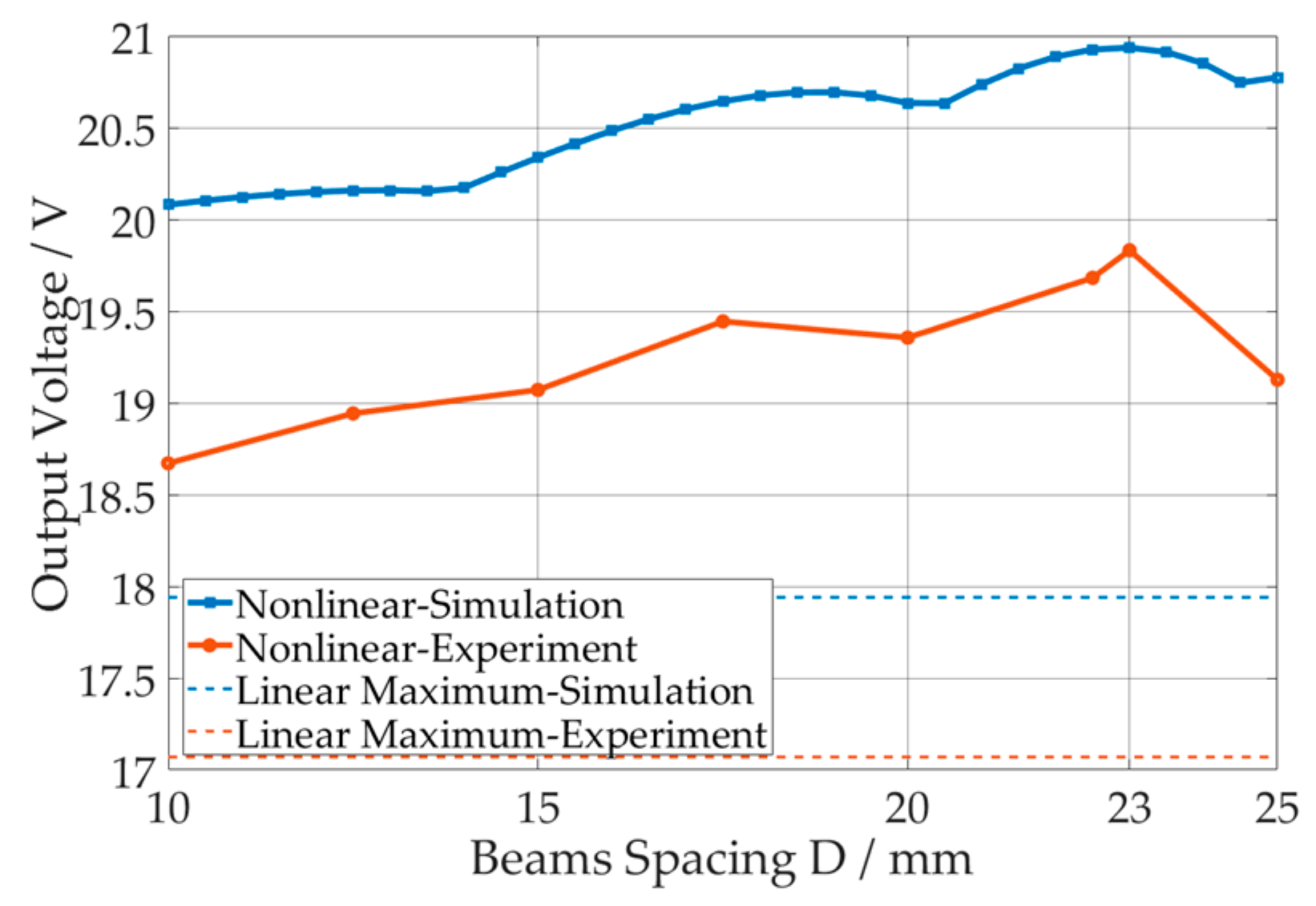
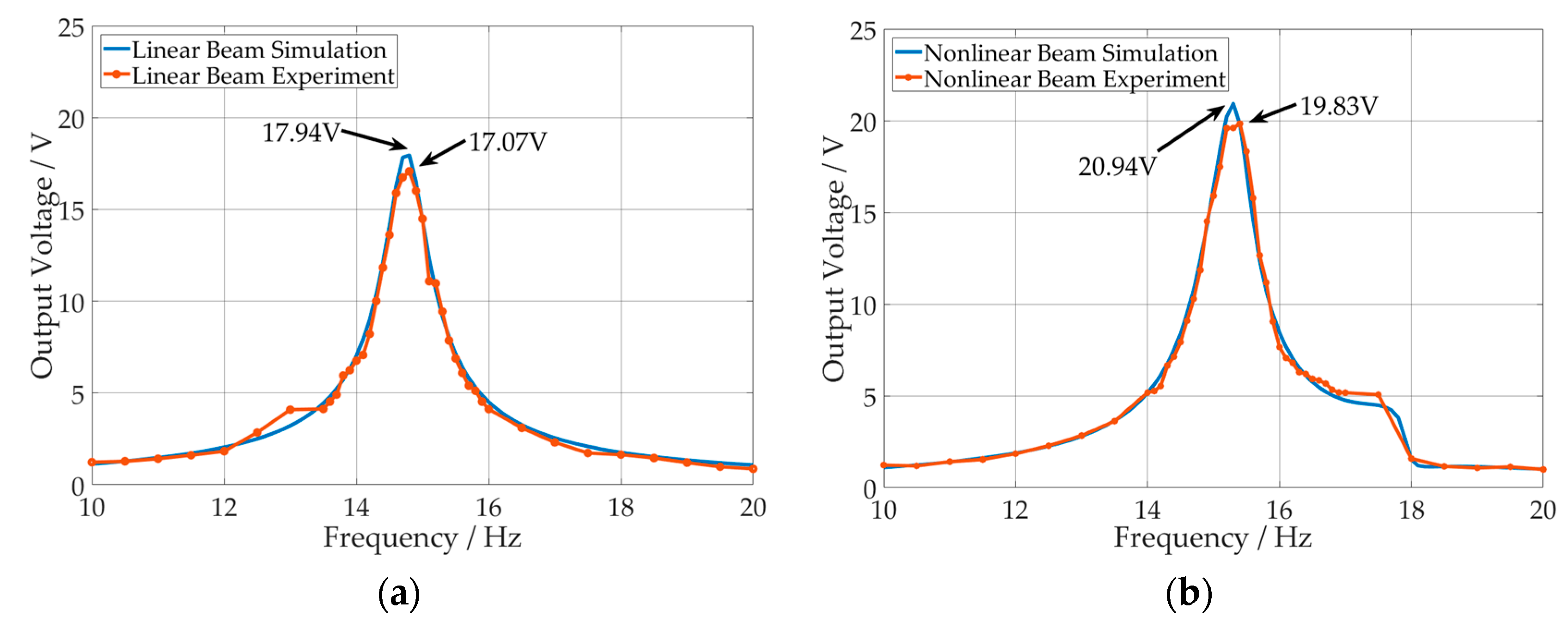
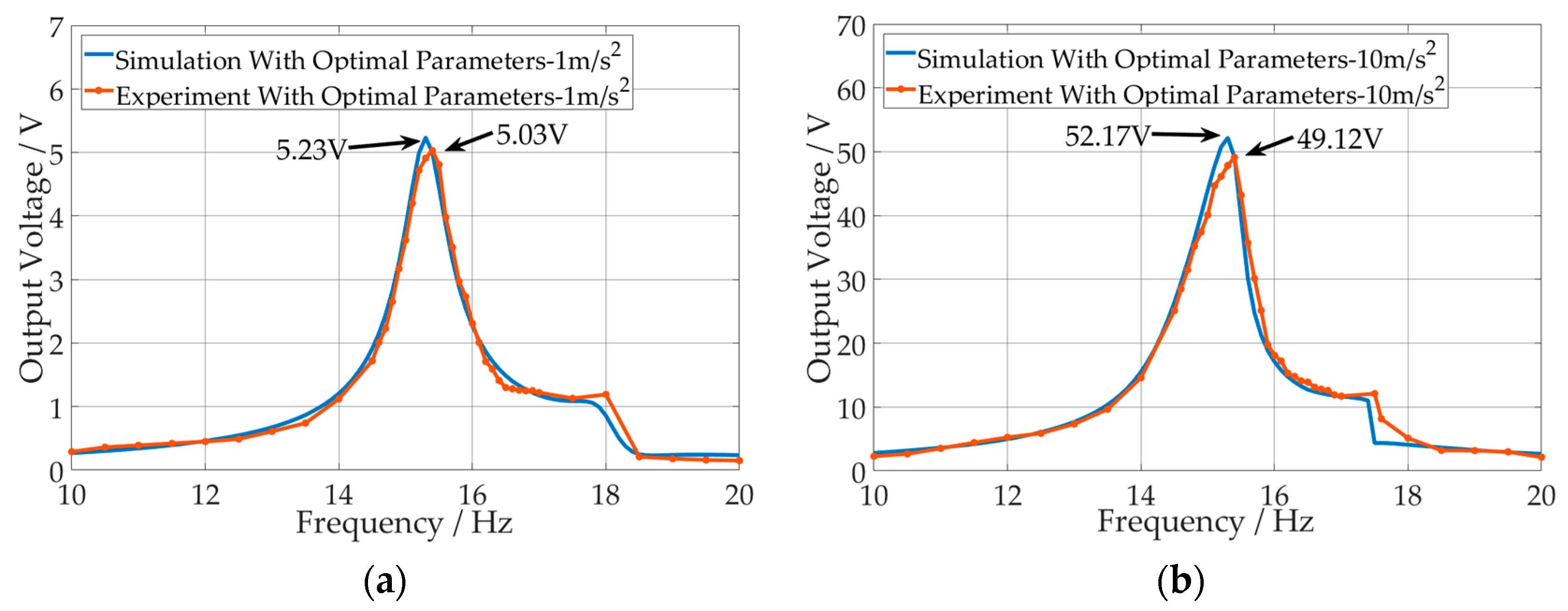
4.1.4. Optimal Results Analysis

Based on the above parameter optimization, the comparison of linear conventional configuration and magnetic coupled configuration are shown in Figure 10. The frequency sweeping of simulation is at a 0.1 Hz interval in the 10–20 Hz range. In the processes of upward sweep in the experiment, 0.1 Hz interval is used in the fast-changing range and 0.5 Hz interval is used in the other ranges.
The experimental results are basically matched with the simulation results, and there is within 6% error in the peak amplitude. In terms of frequency prediction, the nonlinear magnetic coupled beam has an error of 0.1 Hz. Compared with the linear configuration, the nonlinear results show that there is a significant increase in amplitude. The peak output voltage is increased by 16.7% in the simulation and 16.2% in the experiment. If the output power is used as a standard for comparison, which is the square of the voltage, the simulation is increased by 36.2% and the experiment is increased by 35.0%. The bandwidth is evaluated to 5V as the standard, which is a relatively commonly used voltage. The bandwidth increased by 33.3% from 2.1 (13.7–15.8) Hz to 2.8 (14.0–16.8) Hz in simulation and increased by 66.7% from 2.1 (13.8–15.9) Hz to 3.5 (14.0–17.5) Hz in experiment. In summary, a high performance harvester is achieved by magnetic coupling, improved in both amplitude and bandwidth after parameter optimization.
Time series for the output voltage, acceleration in experiment and corresponding phase portraits curve in simulation are shown in Figure 11. In Figure 11g–i, the system enters large-scale periodic state to achieve the optimal amplitude in 15.3 Hz.

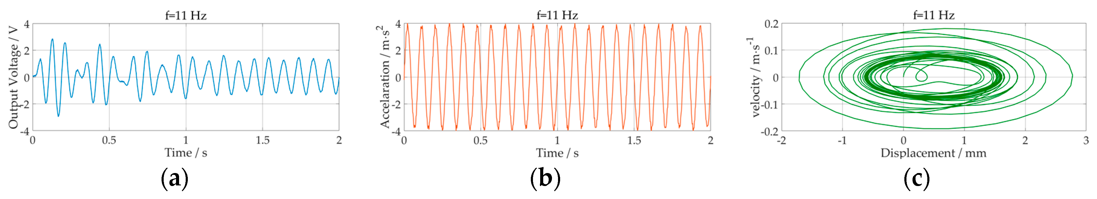
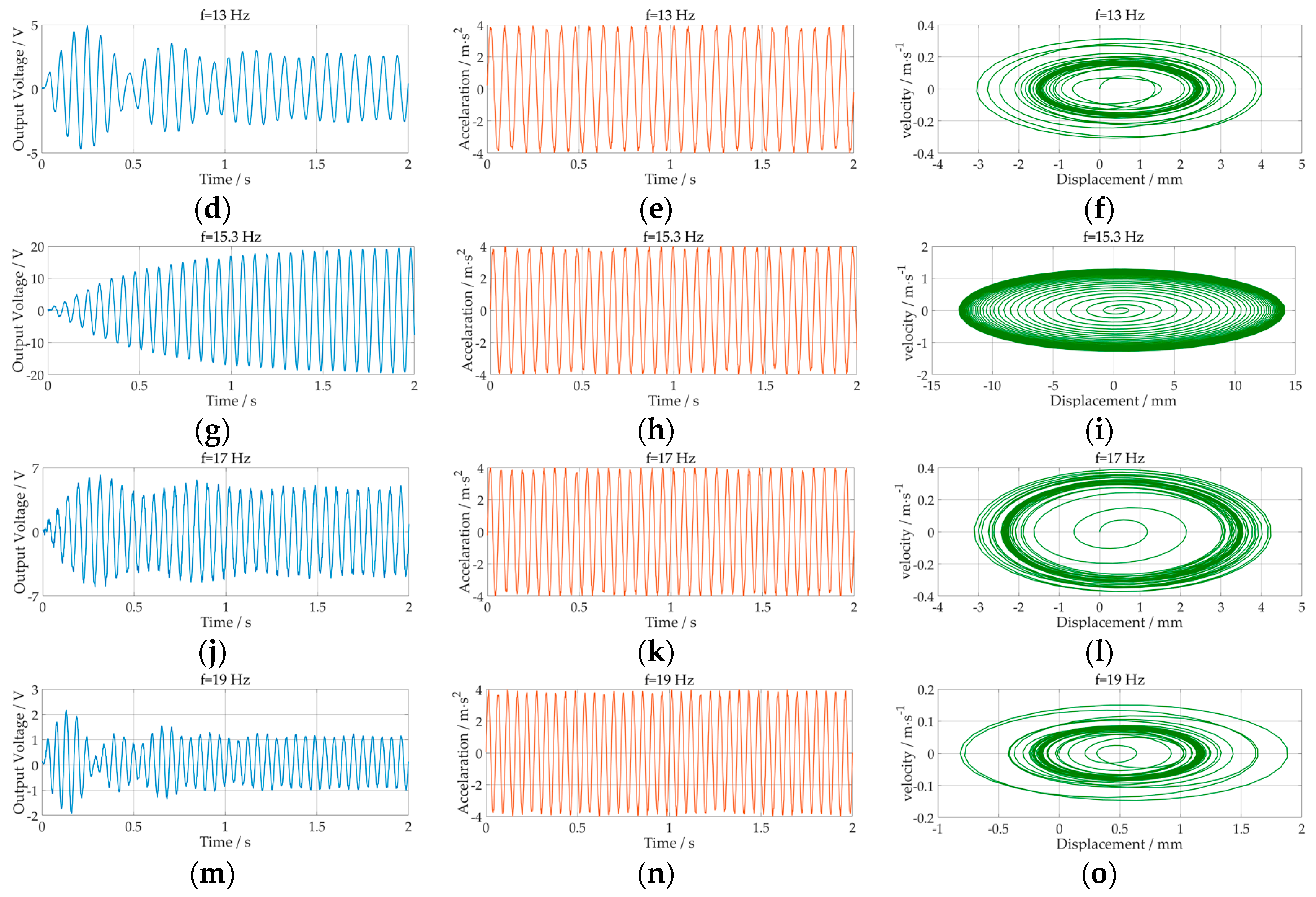
4.1.5. Different Acceleration Test

In order to show the properties of the structure more comprehensively, this section compares the different excitation accelerations and presents them with 1 m/s2 and 10 m/s2. Using a method similar to Section 4.1.3, this section simulates the optimal spacing using the condition of B = 0.12 T, as shown in Figure 12.
Under the acceleration excitation of 1 m/s2, the optimal spacing is 19.5 mm. In the case of 10 m/s2, 33.5 mm is obtained. Combined with 23 mm at 4 m/s2, it can be seen preliminarily that as the excitation increases, the optimal spacing will increase. Experiments and simulations are carried out with the two accelerations under the parameters of the optimal spacing. The experimental procedure is consistent with Section 4.1.4, and the results are shown in Figure 13. It can be seen from the figure that the structure exhibits similar properties at different accelerations, and the model can still predict the voltage within a certain error.

4.2. Comparison with Previous Works

The performance of the magnetic coupled piezoelectric harvester is compared with some reported literatures. The comparison is carried out in several aspects such as size, frequency, excitation, voltage, power and density, which have been summarized in Table 4. The sizes are approximated based on the description in the text. Reference [11] has a lowest voltage since it is based on the electromagnetic method. Reference [15] gets the least amount of energy because of its very small size. It has been observed that the power densities are between 15–55 μW/cm3. The structure described in this paper achieves the highest energy density with a higher acceleration than references [11,22,23]. Compared with other literatures, it can be shown that the magnetic coupled structure has high energy harvesting density potential. At the same time, due to its ease of design and processing, the harvester has a good application prospect.

4.3. Discussion

  • Compared with the conventional cantilever beam energy harvester, the performance has been improved in terms of amplitude and frequency bandwidth by magnetic coupling. The increased performance increases the robustness of the system, which accommodates more complex operating conditions.
  • This paper focuses on the peak voltage, and the peak voltage error under the optimal parameter experiments are less than 6%. Among them, the error is 3.82%, 5.30%, 5.85% under the acceleration condition of 1, 4, 10 m/s2. It can be concluded preliminarily that the error increases with the excitation, but it is still within the acceptable range. In terms of frequency, the peak frequencies of the experiments are both 0.1 Hz larger than the simulation. The main sources of the above errors are the calculation of magnetic force, experimental error, and simplified error of the lumped parameter model.
  • The lumped parameter model of this paper can predict the characteristics of the system within acceptable error and can be used in the structural design. Parameter optimization should be operated in applications to maximize system performance. For example, in this paper, the amplitude can be increased by 35.0% and the 5 V bandwidth is increased by 66.7%.
  • After parameter optimization, the structure in this paper can get more than 3 mW of energy, which is enough to provide energy for some low power consumption devices. For example, the wake-up receiver of wireless sensor networks achieves an ultra-low power consumption of 4.5 nW [38]. ADI’s commercial acceleration sensor ADXL362 consumes 3.6 μW at a sampling rate of 100 Hz, and the MCU ADuCM4050 achieves a low power consumption of 40 μA/MHz. Through a comprehensive power consumption consideration, the wireless sensor system can achieve consumption at “mW” or even “μW” level. Therefore, the energy demand can be met under the settings described in this paper. If the energy is not enough in some applications, a bimorph structure can be utilized to increase the energy.
  • If further power is required, more advanced composite materials can be used to increase the power. For example, the novel magneto-mechano-electric material combines electromagnetic and piezoelectric mechanisms [39], and a 3D-skeletal architecture piezoelectric ceramics can get about 16 times higher energy than the conventional PZT [40]. These materials are all suitable for the structure proposed in this paper because the performance is optimized by increasing the deformation of the cantilever beam. However, it may be increased in terms of cost and additional circuits, and the durability of the new materials should be considered.
  • From the perspective of cost savings, ordinary PZT materials can be used. It is important to note that the magnetic flux density parameter needs to be set smaller. Since the PZT is very brittle, the large magnetic force will increase the deflection and reduce the service life.
  • From the perspective of practical design, the structure of this paper increases the quality and volume of the system, which is increased by about 100%. In terms of cost, since piezoelectric materials are the main cost source, the cost increase is expected to be less than 20%. Therefore, under the condition of satisfying the quality and volume limitation, the structure has a certain cost performance by increasing the power of 35.0%.

5. Conclusions

A high performance magnetic coupled piezoelectric energy harvester is studied in this paper. The process of parameter optimization is discussed in detail and confirmed by experiments. A lumped parameter piezoelectric coupling model considering the magnetic static position is established for this structure. The four configurations of the structure are studied through simulation and “Low beam repulsion mode” is selected due to its high performance potential. The performance of the harvester is evaluated via both analytical simulation and experiments. After parameter optimization, it is found that the optimal beams spacing value exists under different magnet flux densities. As the flux density increases, the optimum spacing gradually increases. With the optimized parameters, the structure of this paper can obtain 3.28 mW harvested power and 3.5 Hz bandwidth, with 5 V as the standard, under harmonic excitation of 4 m/s2. Compared with the conventional single cantilever harvester, the power is increased by 35.0% and the bandwidth is increased by 66.7% experimentally. The harvester has a high performance by enhanced output power in wide operating frequency range and hence can be applied to power the low power consumption devices, such as wireless sensor networks, etc.

Author Contributions

X.R. established the theoretical model and performed the simulation; X.R., Y.L. (Yibo Li) and Z.Z. designed the experiments; X.R., Y.L. (Yue Liu) and X.Z. performed the experiment; X.R. and Y.B. analyzed the data. All authors reviewed the manuscript.

Funding

This research was funded by National Key R&D Program of China (No. 2018YFF0212201 & No. 2016YFF0101802) and Natural Science Foundation of Tianjin (No. 17JCYBJC19300).

Conflicts of Interest

The authors declare no conflict of interest.

References

  1. Babayo, A.A.; Anisi, M.H.; Ali, I. A review on energy management schemes in energy harvesting wireless sensor networks. Renew. Sustain. Energy Rev. 2017, 76, 1176–1184. [Google Scholar] [CrossRef]
  2. Yadav, A.; Goonewardena, M.; Ajib, W.; Dobre, O.A.; Elbiaze, H. Energy management for energy harvesting wireless sensors with adaptive retransmission. IEEE Trans. Commun. 2017, 65, 5487–5498. [Google Scholar] [CrossRef]
  3. Adu-Manu, K.S.; Adam, N.; Tapparello, C.; Ayatollahi, H.; Heinzelman, W. Energy-Harvesting Wireless Sensor Networks (EH-WSNs): A Review. ACM Trans. Sens. Netw. 2018, 14, 10. [Google Scholar] [CrossRef]
  4. Bai, Y.; Jantunen, H.; Juuti, J. Energy Harvesting Research: The Road from Single Source to Multisource. Adv. Mater. 2018, 30. [Google Scholar] [CrossRef] [PubMed]
  5. Orrego, S.; Shoele, K.; Ruas, A.; Doran, K.; Caggiano, B.; Mittal, R.; Kang, S.H. Harvesting ambient wind energy with an inverted piezoelectric flag. Appl. Energy 2017, 194, 212–222. [Google Scholar] [CrossRef]
  6. Wang, H.; Jasim, A.; Chen, X. Energy harvesting technologies in roadway and bridge for different applications—A comprehensive review. Appl. Energy 2018, 212, 1083–1094. [Google Scholar] [CrossRef]
  7. Karami, M.A.; Inman, D.J. Powering pacemakers from heartbeat vibrations using linear and nonlinear energy harvesters. Appl. Phys. Lett. 2012, 100, 042901. [Google Scholar] [CrossRef]
  8. Bassani, G.; Filippeschi, A.; Ruffaldi, E. Nonresonant Kinetic Energy Harvesting Using Macrofiber Composite Patch. IEEE Sens. J. 2018, 18, 2068–2076. [Google Scholar] [CrossRef]
  9. Ahmed, R.; Mir, F.; Banerjee, S. A review on energy harvesting approaches for renewable energies from ambient vibrations and acoustic waves using piezoelectricity. Smart Mater. Struct. 2017, 26, 085031. [Google Scholar] [CrossRef]
  10. Yang, Z.; Zhou, S.; Zu, J.; Inman, D. High-Performance Piezoelectric Energy Harvesters and Their Applications. Joule 2018, 2, 642–697. [Google Scholar] [CrossRef]
  11. Foong, F.M.; Thein, C.K.; Ooi, B.L.; Yurchenko, D. Increased power output of an electromagnetic vibration energy harvester through anti-phase resonance. Mech. Syst. Signal Process. 2019, 116, 129–145. [Google Scholar] [CrossRef]
  12. Feng, Y.; Yu, Z.; Han, Y. High-performance gap-closing vibrational energy harvesting using electret-polarized dielectric oscillators. Appl. Phys. Lett. 2018, 112, 032901. [Google Scholar] [CrossRef] [Green Version]
  13. Fang, Z.W.; Zhang, Y.W.; Li, X.; Ding, H.; Chen, L.Q. Integration of a nonlinear energy sink and a giant magnetostrictive energy harvester. J. Sound Vib. 2017, 391, 35–49. [Google Scholar] [CrossRef]
  14. Wei, C.; Jing, X. A comprehensive review on vibration energy harvesting: Modelling and realization. Renew. Sustain. Energy Rev. 2017, 74, 1–18. [Google Scholar] [CrossRef]
  15. Kim, S.; Towfeeq, I.; Dong, Y.; Gorman, S.; Rao, A.M.; Koley, G. P (VDF-TrFE) film on PDMS substrate for energy harvesting applications. Appl. Sci. 2018, 8, 213. [Google Scholar] [CrossRef]
  16. Reilly, E.K.; Burghardt, F.; Fain, R.; Wright, P. Powering a wireless sensor node with a vibration-driven piezoelectric energy harvester. Smart Mater. Struct. 2011, 20, 125006. [Google Scholar] [CrossRef]
  17. Twiefel, J.; Westermann, H. Survey on broadband techniques for vibration energy harvesting. J. Intell. Mater. Syst. Struct. 2013, 24, 1291–1302. [Google Scholar] [CrossRef]
  18. Dechant, E.; Fedulov, F.; Fetisov, L.Y.; Shamonin, M. Bandwidth Widening of Piezoelectric Cantilever Beam Arrays by Mass-Tip Tuning for Low-Frequency Vibration Energy Harvesting. Appl. Sci. 2017, 7, 1324. [Google Scholar] [CrossRef]
  19. Usharani, R.; Uma, G.; Umapathy, M.; Choi, S.B. A Novel Piezoelectric Energy Harvester Using a Multi-Stepped Beam with Rectangular Cavities. Appl. Sci. 2018, 8, 2091. [Google Scholar] [CrossRef]
  20. Liu, H.; Lee, C.; Kobayashi, T.; Tay, C.J.; Quan, C. Investigation of a MEMS piezoelectric energy harvester system with a frequency-widened-bandwidth mechanism introduced by mechanical stoppers. Smart. Mater. Struct. 2012, 21, 035005. [Google Scholar] [CrossRef]
  21. Wu, Y.; Badel, A.; Formosa, F.; Liu, W.; Agbossou, A. Nonlinear vibration energy harvesting device integrating mechanical stoppers used as synchronous mechanical switches. J. Intell. Mater. Syst. Struct. 2014, 25, 1658–1663. [Google Scholar] [CrossRef]
  22. Liu, S.; Cheng, Q.; Zhao, D.; Feng, L. Theoretical modeling and analysis of two-degree-of-freedom piezoelectric energy harvester with stopper. Sens. Actuators A Phys. 2016, 245, 97–105. [Google Scholar] [CrossRef]
  23. Fan, K.; Tan, Q.; Liu, H.; Zhang, Y.; Cai, M. Improved energy harvesting from low-frequency small vibrations through a monostable piezoelectric energy harvester. Mech. Syst. Signal Process. 2019, 117, 594–608. [Google Scholar] [CrossRef]
  24. Erturk, A.; Hoffmann, J.; Inman, D.J. A piezomagnetoelastic structure for broadband vibration energy harvesting. Appl. Phys. Lett. 2009, 94, 254102. [Google Scholar] [CrossRef] [Green Version]
  25. Ibrahim, A.; Towfighian, S.; Younis, M.I. Dynamics of transition regime in bistable vibration energy harvesters. J. Vib. Acoust. 2017, 139, 051008. [Google Scholar] [CrossRef]
  26. Stanton, S.C.; McGehee, C.C.; Mann, B.P. Nonlinear dynamics for broadband energy harvesting: Investigation of a bistable piezoelectric inertial generator. Physica D 2010, 239, 640–653. [Google Scholar] [CrossRef]
  27. Challa, V.R.; Prasad, M.G.; Shi, Y.; Fisher, F.T. A vibration energy harvesting device with bidirectional resonance frequency tunability. Smart Mater. Struct. 2008, 17, 015035. [Google Scholar] [CrossRef]
  28. Challa, V.R.; Prasad, M.G.; Fisher, F.T. Towards an autonomous self-tuning vibration energy harvesting device for wireless sensor network applications. Smart Mater. Struct. 2011, 20, 025004. [Google Scholar] [CrossRef]
  29. Zhang, G.C.; Chen, L.Q.; Ding, H. Forced vibration of tip-massed cantilever with nonlinear magnetic interactions. Int. J. Appl. Mech. 2014, 6, 1450015. [Google Scholar] [CrossRef]
  30. Zhang, G.C.; Chen, L.Q.; Li, C.P.; Ding, H. Primary resonance of coupled cantilevers subjected to magnetic interaction. Meccanica 2017, 52, 807–823. [Google Scholar] [CrossRef]
  31. Firoozy, P.; Khadem, S.E.; Pourkiaee, S.M. Broadband energy harvesting using nonlinear vibrations of a magnetopiezoelastic cantilever beam. Int. J. Eng. Sci. 2017, 111, 113–133. [Google Scholar] [CrossRef]
  32. Tang, L.; Yang, Y. A nonlinear piezoelectric energy harvester with magnetic oscillator. Appl. Phys. Lett. 2012, 101, 094102. [Google Scholar] [CrossRef]
  33. Abdelkefi, A.; Barsallo, N. Nonlinear analysis and power improvement of broadband low-frequency piezomagnetoelastic energy harvesters. Nonlinear Dyn. 2016, 83, 41–56. [Google Scholar] [CrossRef]
  34. Yuan, T.C.; Yang, J.; Chen, L.Q. A harmonic balance approach with alternating frequency/time domain progress for piezoelectric mechanical systems. Mech. Syst. Signal Process. 2019, 120, 274–289. [Google Scholar] [CrossRef]
  35. Erturk, A.; Inman, D.J. On mechanical modeling of cantilevered piezoelectric vibration energy harvesters. J. Intell. Mater. Syst. Struct. 2008, 19, 1311–1325. [Google Scholar] [CrossRef]
  36. Dutoit, N.E.; Wardle, B.L.; Kim, S.G. Design considerations for MEMS-scale piezoelectric mechanical vibration energy harvesters. Integr. Ferroelectr. 2005, 71, 121–160. [Google Scholar] [CrossRef]
  37. Vokoun, D.; Beleggia, M.; Heller, L.; Šittner, P. Magnetostatic interactions and forces between cylindrical permanent magnets. J. Magn. Magn. Mater. 2009, 321, 3758–3763. [Google Scholar] [CrossRef]
  38. Jiang, H.; Wang, P.H.P.; Gao, L.; Sen, P.; Kim, Y.H.; Rebeiz, G.M.; Hall, D.A.; Mercier, P.P. 24.5 A 4.5 nW wake-up radio with− 69dBm sensitivity. In Proceedings of the 2017 IEEE International Solid-State Circuits Conference (ISSCC), San Francisco, CA, USA, 5–9 February 2017; pp. 416–417. [Google Scholar]
  39. Chu, Z.; Annapureddy, V.; PourhosseiniAsl, M.; Palneedi, H.; Ryu, J.; Dong, S. Dual-stimulus magnetoelectric energy harvesting. MRS Bull. 2018, 43, 199–205. [Google Scholar] [CrossRef]
  40. Zhang, Y.; Sun, H.; Jeong, C.K. Biomimetic Porifera Skeletal Structure of Lead-Free Piezocomposite Energy Harvesters. ACS Appl. Mater. Interfaces 2018, 10, 35539–35546. [Google Scholar] [CrossRef]
Figure 1. Schematic diagram of common nonlinear optimization methods: (a) Stop Blocking Method; (b) Multi-Stable Method; (c) Vertical Magnetic Method.
Applsci 08 02609 g001
Figure 2. Schematic diagram of the magnetic coupled piezoelectric energy harvester.
Applsci 08 02609 g002
Figure 3. Output voltage simulation curve in different modes: (a) Low beam; (b) High beam.
Applsci 08 02609 g003
Figure 4. Experimental platform setup diagrams: (a) Components connection; (b) Energy Harvesting Circuit.
Applsci 08 02609 g004
Figure 5. Experimental prototype: (a) Overview of the platform; (b) Close-up of the harvester.
Applsci 08 02609 g005
Figure 6. Static analysis curves: (a) Magnets Spacing; (b) Deflection.
Applsci 08 02609 g006
Figure 7. Determination of the optimal load resistance.
Applsci 08 02609 g007
Figure 8. Output power maximum at different D and Br: (a) Simulation; (b) Experiment.
Applsci 08 02609 g008
Figure 9. Output voltage at different D with Br = 0.12 T based on simulation and experiment.
Applsci 08 02609 g009
Figure 10. Optimal output voltage: (a) Linear configuration; (b) Magnetic coupled configuration.
Applsci 08 02609 g010
Figure 11. Time series for the output voltage, acceleration in experiment and corresponding phase portraits curve in simulation: (ac) 11 Hz; (df) 13 Hz; (gi) 15.3 Hz; (jl) 17 Hz; (mo) 19 Hz.
Applsci 08 02609 g011aApplsci 08 02609 g011b
Figure 12. Output voltage at different D with Br = 0.12 T based on simulation and experiment.
Applsci 08 02609 g012
Figure 13. Optimal output voltage: (a) 1 m/s2; (b) 10 m/s2.
Applsci 08 02609 g013
Table 1. Parameter list.
SymbolMeaningSymbolMeaning
MEquivalent massHHeight
CEquivalent dampingWWidth
KEquivalent stiffnessLLength
mWeight of the massρDensity
CpCapacity of piezoelectric materialFmagMagnetic force
VpOutput voltageBrFlux density of the magnet
RLoad resistanceμairVacuum permeability
ΘElectromechanical coupling coefficientrRadius of the magnet
μCompensation factorhThickness of the magnet
EElastic Modulus of the beammmagWeight of the magnet
IMoment of inertiadSpacing of the magnets
wDeflectionDSpacing of the beams’ fixed ends
Table 2. Summary of different model features.
Beam ClassificationLow FrequencyHigh Frequency
AttractionSoftening
Double degree-of-freedom
Softening
High Performance
RepulsionHardening
High Performance
Hardening
Double degree-of-freedom
Table 3. Parameters of the prototype.
ComponentMaterialSize (mm)Weight (g)
Cantilever beam1Al-6061T130 × 20 × 0.53.55
Cantilever beam2Al-6061T130 × 20 × 0.755.32
Piezoelectric pitchMFC-M8514-P2101 × 20 × 0.212.01
MagnetNd–Fe–BR10 × 24.72
MassAl/1.02
FrameAcrylic//
Table 4. Comparisons with reported devices.
Ref.Estimated SizeResonance FrequencyExcitationVoltagePowerPower Density
(cm3)(Hz)(m/s2)(V)(μW)(μW/cm3)
[11]217.517.210.16740034.02
[15]0.63017.55.818.5630.93
[19]139.9521.0210V a61.55660047.16
[22]14.421.4322.3542929.8
[23]3.09Random1214815.53
[This Work]63.615.3419.83327751.53
a The article uses the peak-to-peak value of the excitation voltage source to express the acceleration.

