Article

Interference Alignment in Multi-Hop Cognitive Radio Networks under Interference Leakage

1
Department of Electrical and Electronics Engineering, Istanbul Medeniyet University, Uskudar, Istanbul 34700, Turkey
2
Department of Electronics and Communication Engineering, Kocaeli University, Izmit, Kocaeli 41380, Turkey
3
Informatics Institute, Istanbul Technical University, Maslak, Istanbul 34469, Turkey
4
Department of Electrical and Electronics Engineering, Kutahya Dumlupinar University, Kutahya 43100, Turkey
*
Author to whom correspondence should be addressed.
Appl. Sci. 2018, 8(12), 2486; https://doi.org/10.3390/app8122486
Submission received: 6 November 2018 / Revised: 21 November 2018 / Accepted: 25 November 2018 / Published: 4 December 2018

Abstract

:
In this work, we examine the interference alignment (IA) performance of a multi-input multi-output (MIMO) multi-hop cognitive radio (CR) network in the presence of multiple primary users. In the proposed architecture, it is assumed that linear IA is adopted at the secondary network to alleviate the interference between primary and secondary networks. By doing so, the secondary source can communicate with the secondary destination via multiple relays without causing any interference to the primary network. Even though linear IA can suppress the interference in CR networks considerably, interference leakages may occur due to a fast fading channel. To this end, we focus on the performance of the secondary network for two different cases: (i) the interference is perfectly aligned; (ii) the impact of interference leakages. For both cases, closed-form expressions of outage probability and ergodic capacity are derived. The results, which are validated by Monte Carlo simulations, show that interference leakages can deteriorate both system performance and the diversity gains considerably.

1. Introduction

As mobile devices become widespread, wireless data traffic has been increasing significantly in the recent years. In order to meet the ever-increasing demand for high quality wireless communication standards, the Third-Generation Partnership Project (3GPP) and Long-Term Evolution (LTE) technologies have emerged [1,2]. Regarding the deployment of the next-generation wireless communication systems, the corresponding growth in the demand for wireless radio spectrum resources will appear. With a rapid increase in the number of connected devices and mobile users, improving spectrum utilization has now become an important concern in designing next-generation wireless communication networks [3]. Unfortunately, this situation will cause a severe shortage of spectrum resources. Thus, the solution methods for spectrum utilization have been attracting attention in recent years [4].
One of the candidates for solving the problem of spectrum shortage is the cognitive radio (CR) technology. CR has attracted considerable interest, as it can cope with the spectrum under-utilization phenomenon, as the efficient usage of the limited spectrum is important for mobile applications. CR can remedy this problem by allowing secondary (unlicensed) users (SUs) to share the same spectrum band with the primary (licensed) users (PUs). Thus, CR is a promising solution for providing quality of service and overcoming the problem of spectrum limitation in wireless networks. At the moment, spectrum usage is assigned for specific services with limited bandwidth based on the regulatory policy. This means that the unlicensed users will not be able to use the licensed frequency bands. However, the inefficient use of the licensed spectrum has been reported. CR allows the unlicensed users to exploit the unused frequency bands dynamically without causing harmful interference to the licensed users. For this reason, it has been proposed to improve spectral utilization and efficiency [5,6,7,8]. That is to say, CR is an inspiring approach for wireless communication systems that can alleviate the spectrum scarcity problem and utilize the existing spectrum resources efficiently. The CR network is composed of a primary network (PN) in which the licensed users of the spectrum are employed and a secondary network (SN), whose unlicensed users can access the spectrum opportunistically. SN users can access the licensed spectrum by three well-known techniques: underlay, overlay, and interweave [5,6,7]. In the underlay approach, the SU can simultaneously communicate with the PU using the PU’s spectrum guaranteeing that the SU does not cause any harmful interference to the PU. In this scheme, the interference caused by the transmission of the SUs should not exceed an acceptable threshold. That means, the underlay method allows SU transmission as long as the interference remains under the predefined threshold value [9]. In the overlay approach, the SU has knowledge about the PU’s transmitting information and how it is encoded. While the PU broadcasts its information periodically, the SU can obtain it by decoding the data sequence; thus, the interference can be partially or completely removed. The interweave paradigm is based on the concept of opportunistic communications. The idea was raised from the underutilized spectrum. Spectrum holes, which are not fully utilized most of the time, can be exploited by SUs to operate in the licensed bands. Thus, the spectrum utilization is enhanced by the opportunistic reuse of the spectrum holes. The interweave approach requires the detection of the PUs’ activity in the licensed frequency band [10].
CR technology can be capable of utilizing the spectrum efficiently as long as the interference between PUs and SUs is perfectly aligned. To this end, interference alignment (IA) is an important approach for CR to recover the desired signal of the PU or SU by utilizing the precoding and suppression matrices of the channel matrix, which consolidates the interference beam or matrix into one subspace in order to eliminate them. This paper focuses on the interference alignment in CR networks considering multiple hops in the underlay scheme.

1.1. Related Works

There are various IA techniques that are trying to provide interference-free communications in CR networks. In the linear IA technique, the channel matrix is assumed to be perfectly known at the transmitter and receiver side of the PN [11,12,13,14]. In the literature, linear IA was adopted in CR interference channels in [15,16,17,18] and the references therein. In [15], the adaptive power allocation schemes were considered for linear IA-based CR networks where the outage probability and sum rate were derived. In [16], the adaptive power allocation was studied for linear IA-based CR using antenna selection at the receiver side, whereas [17] enhanced the security of CR networks by using a zero-forcing precoder. A similar work was proposed in [18] to improve the overall outage performance of the interference channel by using power allocation optimization. These studies show that interference management is an important issue for all multi-user wireless networks.
Most recently, multi-hop relaying, which is an effective way of enhancing reliability, connectivity, and coverage area, was introduced in CR networks [19,20,21]. In these papers, the authors studied the multi-hop cognitive relay networks under interference power constraints and provided a comprehensive performance study including the closed-form expressions for the outage probability, bit error rate (BER), and ergodic capacity. The paper [22] considered the performance of multi-hop CR networks with imperfect channel state information (CSI). Besides, the performance metrics of the secondary multi-hop networks covering outage probability, BER, and ergodic capacity were derived over Rayleigh fading channels. In [23,24], the authors considered the cognitive multi-hop system model and analyzed the performances over a generalized-K distribution. The outage probability analysis of a single-hop CR network was studied in [25] by considering multi-hop relaying in PN. Hussein et al. in [26] and the authors in [27] considered a multi-input multi-output (MIMO) multi-hop CR network and investigated its detailed performance. Finally, [28] demonstrated the effect of cluster-based relaying in the implementation complexity and provided the performance of a multi-hop cognitive relaying system in terms of outage probability, symbol error rate (SER), and ergodic capacity.

1.2. Motivation and Contributions

Even though cognitive multi-hop transmission offers numerous advantages to SUs, the primary-secondary interference is one of the most challenging issues to be solved in CR networks. To this end, IA, which can design coordinated signals to eliminate the interference in PU-SU, has become preferable [29]. Motivated by the advantages of multi-hop relaying and IA, herein, we investigate the interplay of the number of hops, relays, interference alignment, and interference leakage. Our main contributions are as follows:
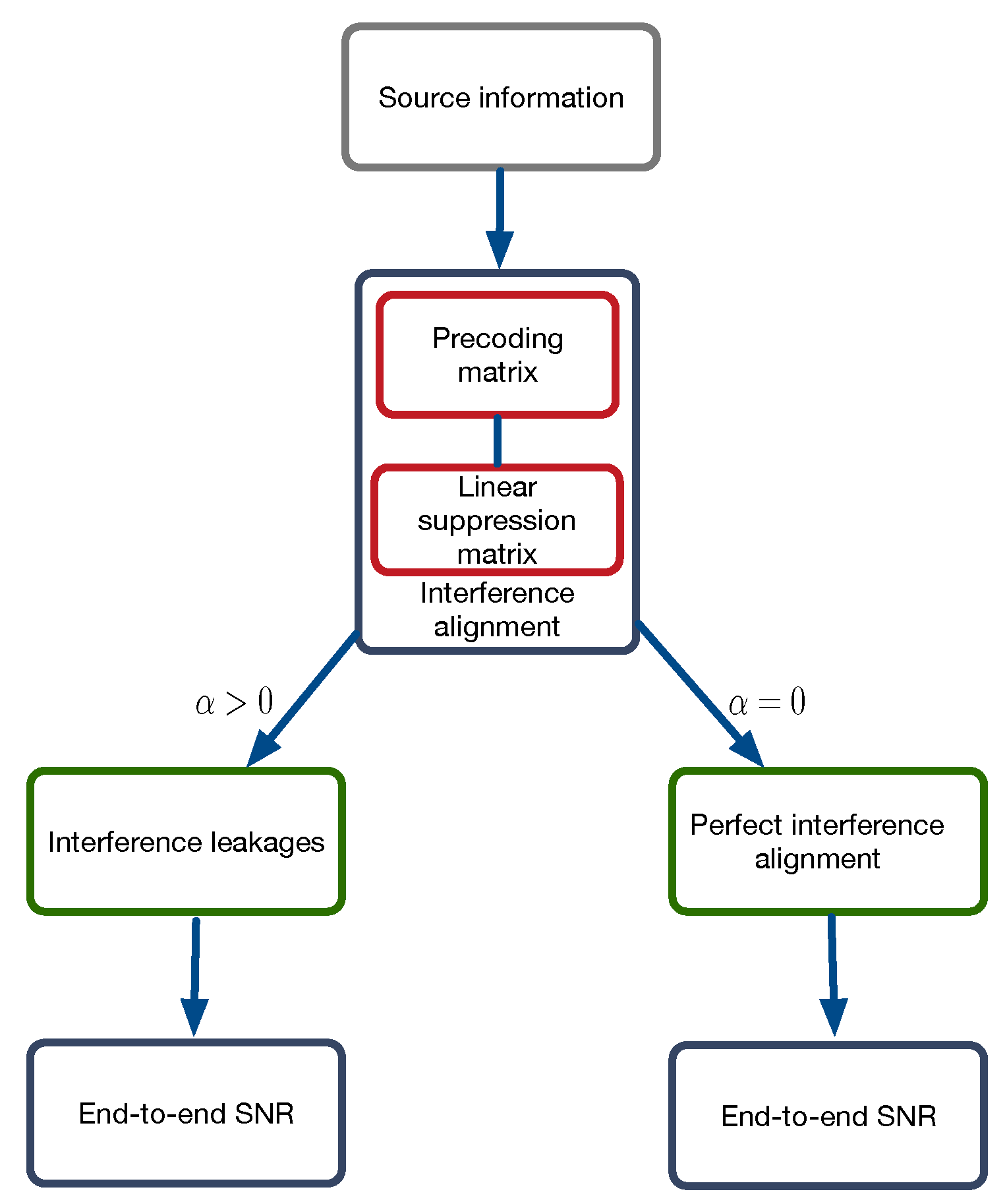
  • A decode-and-forward (DF) multi-hop SN is considered, and end-to-end SNRs are derived for two cases: (1) perfect interference alignment; (2) in the presence of interference leakages.
  • Exact outage probability is derived for perfect IA and interference leakages.
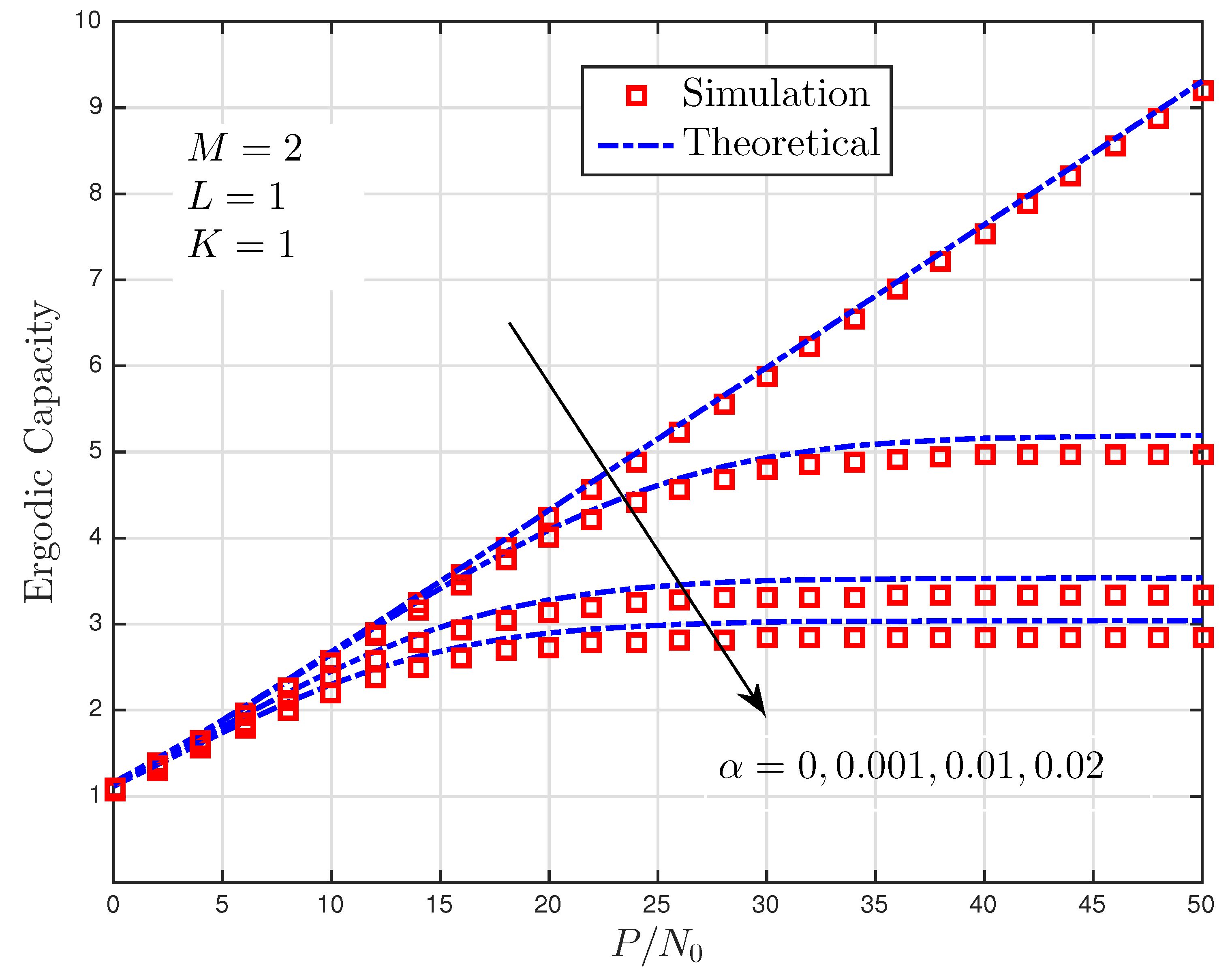
  • Approximate ergodic capacity expressions are derived for both cases.

1.3. Paper Organization

The rest of the paper is organized as follows: We introduce the signal and system model in Section 2. The outage probability analysis is given in Section 3. Section 4 presents the performance evaluations for the ergodic capacity. Numerical results are discussed in Section 5. Finally, Section 6 concludes the paper.

2. Signal and System Model

This paper considers a cognitive multi-hop relay-aided network with L PUs and two SUs in which the secondary source S wishes to communicate with the secondary destination D over K 1 closely-located DF relays, as shown in Figure 1. We assume that all terminals are operating in a half-duplex fashion, and the direct path between S to D is not available due to heavy shadowing or large path loss effect. The uniformly-located relay terminals are clustered together and thus experiencing the same scale of fading even though the instantaneous SNR varies. In the SN, each node is equipped with M transmit/receive antennas applying maximal ratio transmission (MRT) and maximum ratio combining (MRC) techniques at the transmitter and receiver, respectively. In underlay CRNs, the transmit powers of the SUs are generally set to a predefined power level to meet the interference power constraints of the PUs [30]. However, in the proposed scheme shown in Figure 2, we adopt the linear IA method to mitigate the interference occurring at the SN without reducing the powers of the SUs. With the aid of precoding and linear suppression matrices, the single symbol detection at the i th hop (or i + 1 th relay) can be expressed as [31]:
y R i + 1 = U R i + 1 H H R i R i + 1 V R i x s + α U R i + 1 H j = 1 L H P j R i + 1 V P j x j + U R i + 1 H n R i + 1 ,
where x s is the source signal, x j is the information of the primary user, H R i R i + 1 denotes the channel information at the i th hop of the SN, H P j R i + 1 denotes the channel coefficients matrix between PN and SN, V and U denote the corresponding precoding and linear suppression matrices, α gives the interference leakage coefficient varying between 0 and 1 [32], n R i + 1 is the zero-mean unit-variance ( σ n R i + 1 2 = I ) circularly symmetric additive white Gaussian noise (AWGN) vector, and ( . ) H stands for the Hermitian operation. Note that all signal and system model parameters are listed in Table 1. The interference between PN and SN can be perfectly aligned if the following conditions are satisfied [31]:
U R i + 1 H H P j R i + 1 V P j = 0 Rank U R i + 1 H H P j R i + 1 V P j = d ,
where d is the data stream transmitted by each user [33]. Using the ideal linear IA assumption, (1) can be expressed as:
y R i + 1 = H ^ R i R i + 1 x s + n ^ R i + 1 ,
where H ^ R i R i + 1 U R i + 1 H H R i R i + 1 V R i and n ^ R i + 1 U R i + 1 H n R i + 1 .

2.1. Interference Alignment Approach and End-to-End SNR Analysis

Throughout the paper, we apply the linear IA scheme to align the interference occurring between the PN and the SN. In order to suppress the interference signal, we use a minimum mean squared error (MMSE)-based decoder, which aims to maximize the capacity at the receiver part. The size of precoding matrix at each transmitter node V c , ( c P j , R i ) and the suppression matrix of relay receiver at the i th hop U R i + 1 are M × M 2 and M 2 × M , respectively, where M is a positive even number. We assume that V c = P c Q c X c , where Q c is an M × M 2 matrix, whose columns form the orthonormal basis for V c and X c . X c is an M 2 × M 2 unitary matrix, which is obtained by using QR decomposition of the precoding matrix V c . Besides, P c is the average power of each stream as P c = 2 P c / M where P c , ( c P j , R i ) is the total transmit power at the transmitter side.
The suppression matrix at the i th hop can be written as U R i + 1 = U ˜ R i + 1 U ¯ R i + 1 [34]. When all CSI is known at each receiver node, the first term of the suppression matrix is obtained as:
U ¯ R i + 1 = H e f , R i R i + 1 H j = 1 L P P j P R i H e f , P j R i + 1 H e f , P j R i + 1 H + σ n 2 P R i I 1 ,
where H e f , c R i + 1 = H c R i + 1 Q c , ( c P j , R i ) denotes the effective channel matrix and σ n 2 is the noise variance. Then, applying the Cholesky factorization as:
U ¯ R i + 1 j = 1 L P P j H e f , P j R i + 1 H e f , P j R i + 1 H + σ n 2 I U ¯ R i + 1 H = ζ R i + 1 ζ R i + 1 H ,
ζ R i + 1 can be obtained. The second term of the suppression matrix is calculated as U ˜ R i + 1 = S R i + 1 H ζ R i + 1 1 , where S R i + 1 is obtained by using singular-value decomposition (SVD) as H R i + 1 = S R i + 1 Λ R i + 1 D R i + 1 H and H R i + 1 denotes the M 2 × M 2 block channel matrix H R i + 1 = ζ R i + 1 1 U ¯ R i + 1 H e f , R i R i + 1 . Finally, the suppression matrix can be written as a multiplication of these two terms:
U R i + 1 = S R i + 1 H ζ R i + 1 1 U ¯ R i + 1 .
Interested readers are referred to [34] and the references therein for a review of decoding matrix design. As U R i + 1 ( j = 1 L P R j H e f , R i R i + 1 H e f , R i R i + 1 H + σ n 2 I ) U R i + 1 H = I , the interference can be aligned.
With the aid of the proposed IA approach, the interference can be perfectly aligned in the CR network. By doing so, the hop-by-hop transmission can be accomplished via the single-input and single-output (SISO) channel if one data stream is sent at each transmitter [15]. Thereby, the instantaneous SNRs between S R 1 , R i R i + 1 , and R K 1 D can be expressed as:
Γ S R 1 = P S | h S R 1 | 2 σ N 2 , Γ R i R i + 1 = P R i | h R i R i + 1 | 2 σ N 2 ,   and Γ R K 1 D = P R K 1 | h R K 1 D | 2 σ N 2 ,
where P S , P R i , and P R K 1 denote the transmit powers of S, R i , and R K 1 . h S R 1 , h R i R i + 1 , and h R K 1 D denote the channel fading coefficients between S R 1 , R i R i + 1 , and R K 1 D hops, respectively, which are modeled as zero mean and unit variance.

2.2. End-to-End SNRs in the Presence of Interference Leakage

In the presence of interference leakage, in other words, when the interference is not perfectly aligned, i.e., α 0 , leakages occur, and the instantaneous SNRs can be expressed as:
Γ S R 1 = P S | | H S R 1 | | 2 σ N 2 1 + α j = 1 L P j | | H P j R 1 | | 2 σ N 2 , Γ R i R i + 1 = P R i | | H R i R i + 1 | | 2 σ N 2 1 + α j = 1 L P j | | H P j R i + 1 | | 2 σ N 2   and Γ R K 1 D = P R K 1 | | H R K 1 D | | 2 σ N 2 1 + α j = 1 L P j | | H P j D | | 2 σ N 2 ,
where | | · | | denotes the Frobenius norm.

3. Outage Probability Analysis

In this section, the exact outage probability expression is derived for two different cases: (i) the interference is perfectly aligned; (ii) the interference leakages occur due to imperfect IA. Outage probability can be defined as the outage probability of the overall system. In other words, the system is in outage if at least one of the hops is in outage. Mathematically, it can be expressed as:
P out = 1 i = 1 K 1 ( 1 P out ( i ) ) ,
where P out ( i ) is the outage probability of the i th hop.

3.1. Outage Probability Performance of the Perfect IA Scheme

As described in the previous section, when the PN-SN interference is aligned, the system works in the SISO fashion if one data stream is sent at each transmitter [15]. With the aid of (7), P out , P ( i ) can be expressed as:
P out , P ( i ) = Pr [ Γ R i R i + 1 ( i ) < γ t h ] ,
where γ t h is the threshold value for acceptable communication quality. As we assume that all paths are modeled with independent and identically-distributed Rayleigh fading, the cumulative distribution function (cdf) of Γ R i R i + 1 ( i ) can be expressed as:
P out , P ( i ) = 1 exp γ t h γ ¯ R i R i + 1 ,
where γ ¯ R i R i + 1 is the average SNR of the R i R i + 1 hop describing the outage probability of the first K 2 hops. For the last two hops, the outage probability can be expressed as [35]:
P out , P ( K 1 ) = Pr [ min ( Γ R K 2 R K 1 ( i ) , Γ R K 1 D ( i ) ) < γ t h ] = 1 Pr [ Γ R K 2 R K 1 < γ t h ] Pr [ Γ R K 1 D < γ t h ] .
Similar to (11), P out , P ( K 1 ) can be expressed as:
P out , P ( K 1 ) = 1 exp γ t h γ ¯ R K 2 R K 1 exp γ t h γ ¯ R K 1 D .
By substituting (13) and (11) into (9), outage probability can be obtained.

3.2. Outage Probability in the Presence of Interference Leakages

To compute the outage probability of the first K 2 hops in the presence of interference leakages, we express (8) as Γ R i R i + 1 = γ R i R i + 1 1 + γ j R i + 1 I , where γ R i R i + 1 = P R i | | H R i R i + 1 | | 2 σ N 2 and γ j R i + 1 I = j = 1 L P j | | H P j R i + 1 | | 2 σ N 2 . Then, the probability density function (pdf) of γ R i R i + 1 can be expressed as [36]:
f γ R i R i + 1 ( γ ) = γ M 2 1 exp γ / γ ¯ R i R i + 1 γ ¯ R i R i + 1 M 2 M 2 1 ! ,
and the pdf of γ j R i + 1 I can be defined as:
f γ j R i + 1 I ( γ ) = γ L M 2 1 exp γ / ( α γ ¯ j R i + 1 ) α γ ¯ j R i + 1 L M 2 L M 2 1 ! .
Then, the cdf of Γ R i R i + 1 can be written as [27]:
F Γ R i R i + 1 ( γ ) = 0 F γ R i R i + 1 ( ( x + 1 ) γ ) f γ j R i + 1 I ( x ) d x .
We can find F γ R i R i + 1 ( γ ) by taking the integral of f γ R i R i + 1 ( γ ) with respect to γ . Then, by substituting F γ R i R i + 1 ( γ ) and f γ j R i + 1 I ( γ ) into (16), F γ R i R i + 1 ( γ ) can be obtained as:
F Γ R i R i + 1 ( γ ) = 1 exp γ γ ¯ R i R i + 1 n = 0 M 2 1 γ γ ¯ R i R i + 1 n 1 n ! × 1 ( α γ ¯ j R i + 1 ) L M 2 U L M 2 , L M 2 + 1 , γ γ ¯ R i R i + 1 + 1 α γ ¯ j R i + 1 ,
where U ( · , · , · ) is Tricomi’s confluent hypergeometric function [37]. As P out , I ( i ) = F Γ R i R i + 1 ( γ t h ) , the outage probability for the first K 2 hops can be derived. With the aid of (17), for the last two hops, P out , I ( K 1 ) can be expressed as:
P out , I ( K 1 ) = F Γ R K 2 R K 1 ( γ t h ) + F Γ R K 1 D ( γ t h ) F Γ R K 2 R K 1 ( γ t h ) F Γ R K 1 D ( γ t h ) .
By substituting (17) into (18) and after replacing superscripts R i with R K 2 and R K 1 and R i + 1 with R K 1 and D, P out , I ( K 1 ) can be obtained. With the aid of (9), outage probability can be derived.

4. Ergodic Capacity

Ergodic capacity can be defined as the maximum achievable mutual information from S to D, and it can be expressed as:
C e r g = 1 K E log 2 ( 1 + γ e 2 e ) ,
where E [ · ] denotes the expectation operator. By substituting γ e 2 e = min ( Γ S R 1 , Γ R 1 R 2 , , Γ R K 1 D ) into (19), the ergodic capacity can be expressed as:
C e r g = 1 K E log 2 ( 1 + min ( Γ S R 1 , Γ R 1 R 2 , , Γ R K 1 D ) ) .
With the aid of Jensen’s inequality, ergodic capacity can be upper bounded as:
C e r g up 1 K log 2 1 + min E [ Γ S R 1 ] , E [ Γ R 1 R 2 ] , , E [ Γ R K 1 D ] ,
and E [ Γ R i R i + 1 ] can be obtained by using the following formula:
E [ Γ R i R i + 1 ] = 0 1 F Γ R i R i + 1 ( γ ) d γ .

4.1. Ergodic Capacity For Perfect IA

Using (11), after replacing γ t h with γ , the cdf of the i th hop can be expressed as:
F Γ R i R i + 1 ( γ ) = 1 exp γ γ ¯ R i R i + 1 .
By substituting (23) into (22), E [ Γ R i R i + 1 ] can be found as γ ¯ R i R i + 1 . Hence, C e r g up can be expressed as:
C e r g , P up 1 K log 2 1 + min γ ¯ S R 1 , γ ¯ R 1 R 2 , , γ ¯ R K 1 D .
Note that E [ Γ S R 1 ] and E [ Γ R K 1 D ] can be found similarly.

4.2. Ergodic Capacity in the Presence of Interference Leakages

With the aid of Jensen’s inequality and (20), ergodic capacity in the presence of interference leakages can be expressed as:
C e r g up , I = 1 K log 2 E 1 + min P S | | H S R 1 | | 2 σ N 2 1 + α j = 1 L P j | | H P j R 1 | | 2 σ N 2 , P R 1 | | H R 1 R 2 | | 2 σ N 2 1 + α j = 1 L P j | | H P j R 2 | | 2 σ N 2 , , P R K 1 | | H R K 1 D | | 2 σ N 2 1 + α j = 1 L P j | | H P j D | | 2 σ N 2 .

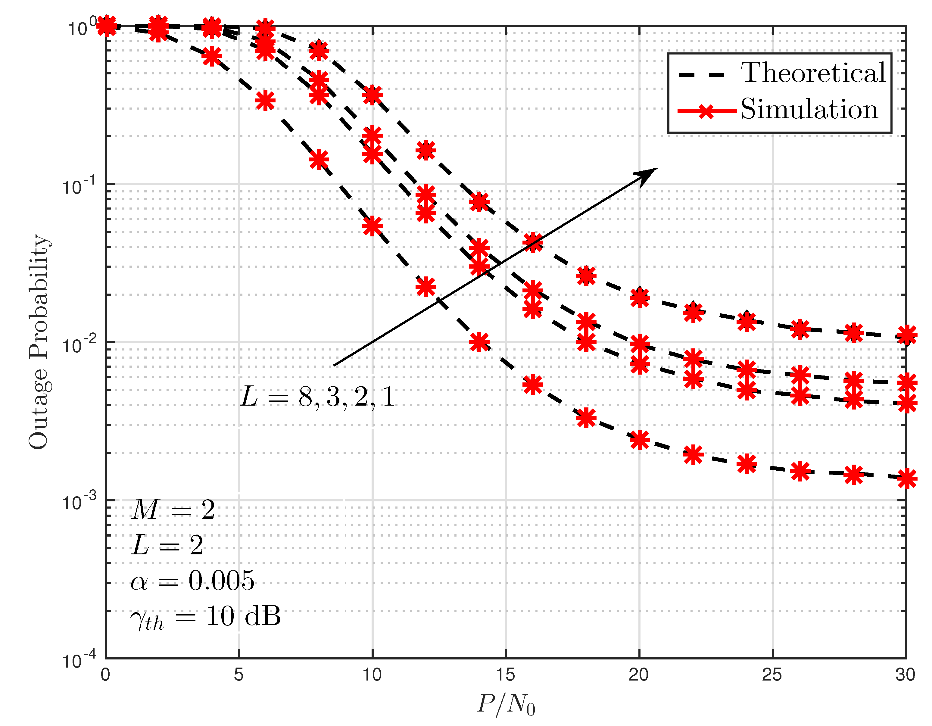
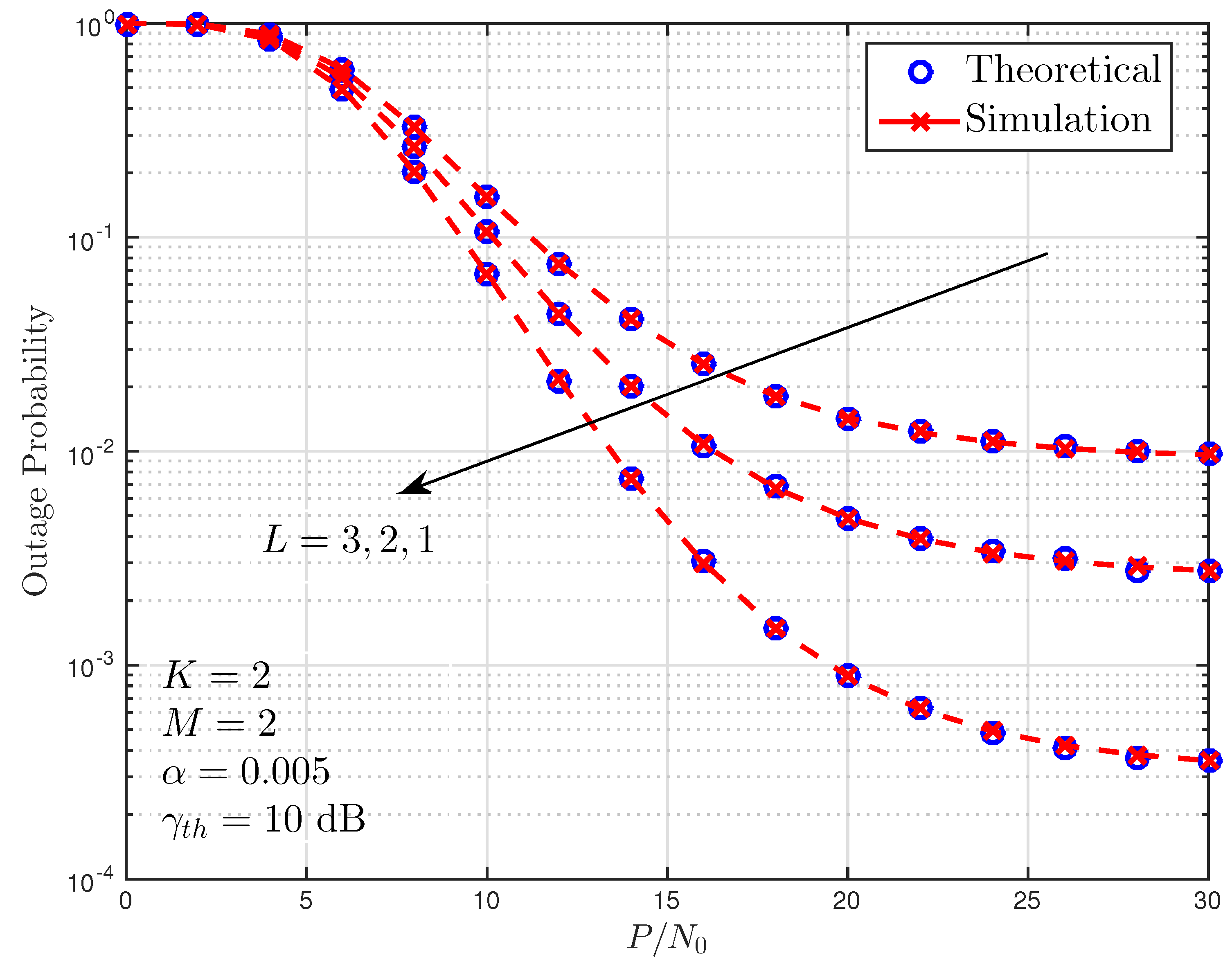
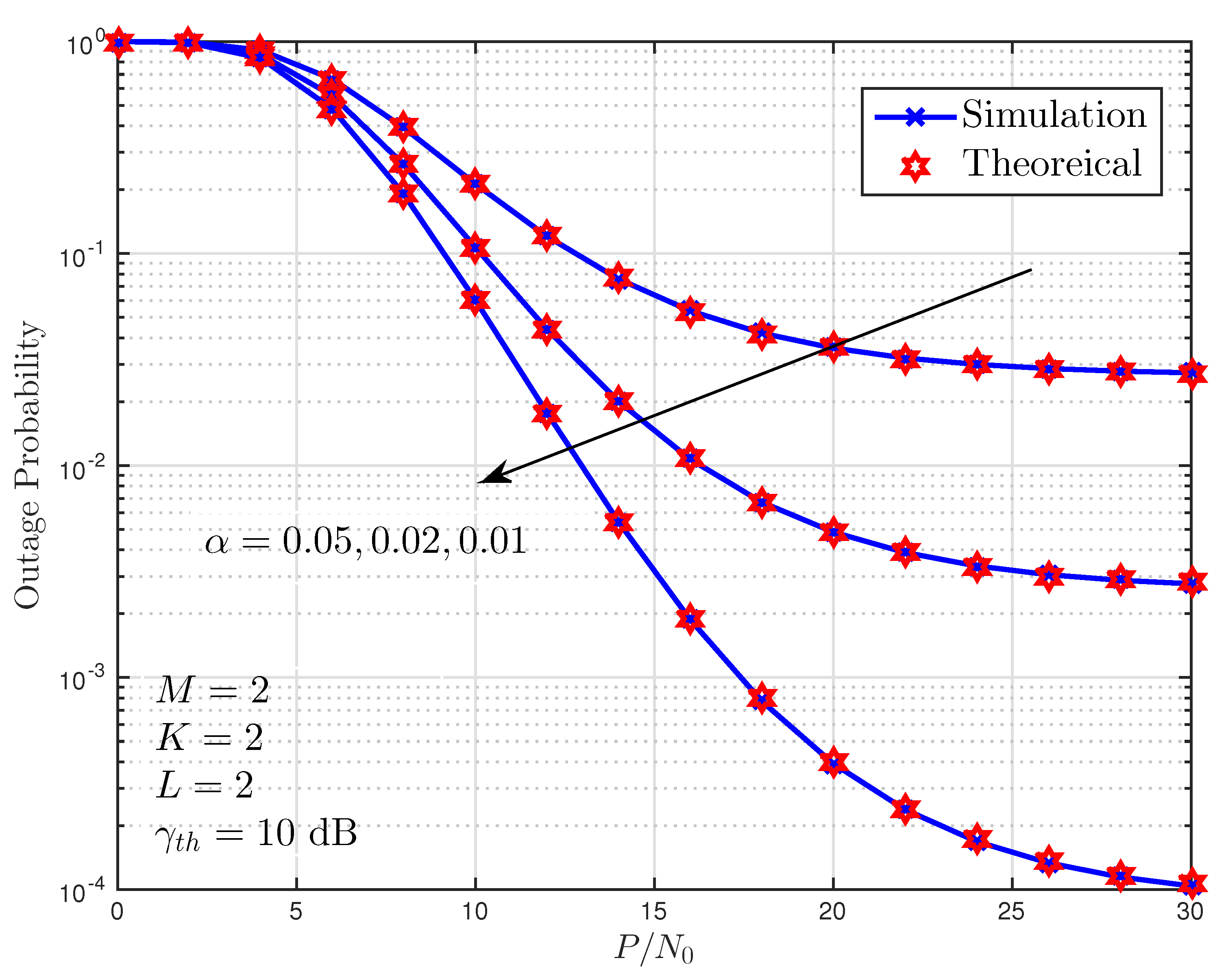
5. Numerical Results

In this section, Monte Carlo simulations are carried out to verify the theoretical results. Without any loss of generality, we assume that the transmit powers at S and R i are given as P S = P R i = P . Moreover, the noise power is taken as N 0 for all hops, and γ t h = 10 dB, unless otherwise stated.
Figure 3 illustrates the outage probability performance of the SN for different numbers of hops when M = L = 2 and α = 0.005 . As can be seen from the figure, outage probability performance worsens as the number of hops increase. This is due to the fact that the number of interferers increase as the number of hops increase. As for example, almost 30 dB is needed to achieve P o u t = 10 2 at K = 8 , while when K = 2 , 18 dB is enough to achieve the same outage probability performance. Moreover, the theoretical curves verify the Monte Carlo simulations.
In Figure 4, the outage probability performance of the considered scheme is depicted for different numbers of interferers (PUs). As can be seen, as the number of interferers increase, the performance degrades. Moreover, the slopes of the curves verify that the diversity gain deteriorates as the number of interferers increase.
Figure 5 illustrates P o u t with respect to P / N 0 of the considered scheme for three different interference leakage values, i.e., α = 0.01 , 0.02 , 0.05 . The other parameters are taken as M = 2 , K = 2 , L = 2 . As can be seen from Figure 5, the best P o u t performance can be obtained when α = 0.01 , and the performance worsens as α increases.
Figure 6 depicts the impact of various interference leakage levels on the performance of the multi-hop SN. As observed from the figure, ergodic capacity performance of the proposed scheme degrades as the impact of interference leakage enhances. On the contrary, when the interference is aligned, the capacity of the secondary network can achieve 10 bits/Hz at 50 dB. Comparing the derived approximate ergodic capacity with the simulation, it can be observed that the theoretical results match almost perfectly with the simulations.

6. Conclusions

In this work, we investigate the IA performance of the cognitive multi-hop network in the presence of multiple primary users. For the proposed scheme, we derived closed-form outage probability and ergodic capacity expressions for Rayleigh fading channel. The results, which were validated with the simulations, show that the system performance degraded as the number of interferers and/or leakage level increased.
This work can be extended to various practical scenarios where relays are affected both by primary-secondary interference and nodes mobility. Moreover, different clustering and/or relay selection approaches can be adopted, and the system performance of the overall multi-hop CR network can be presented.

Author Contributions

The authors E.E. and S.A.Ç. contributed to the methodology, validation, and writing; H.A., M.N., and A.B. contributed to the writing, investigation, and software; L.D.-A. contributed to the conceptualization, review, and editing.

Funding

This research received no external funding.

Acknowledgments

The content of this study has partially been submitted to the IEEE 41st International Conference on Telecommunications and Signal Processing (TSP 2018) [38].

Conflicts of Interest

The authors declare no conflict of interest.

References

  1. Ericsson. Mobile Data Surpasses Voice, Stockholm, Sweden. 2010. Available online: http://www.ericsson.com/thecompany/press/releases/2010/03/1396928 (accessed on 29 October 2018).
  2. Dahlman, E.; Parkvall, S.; Skold, J.; Beming, P. 3G Evolution: HSPA and LTE for Mobile Broadband; Academic Press: New York, NY, USA, 2010. [Google Scholar]
  3. Yucek, T.; Arslan, H. A survey of spectrum sensing algorithms for cognitive radio application. IEEE Commun. Surv. Tutor. 2009, 11, 116–130. [Google Scholar] [CrossRef]
  4. Li, Q.; Hu, R.Q.; Qian, Y.; Wu, G. Cooperative communications for wireless networks: Techniques and applications in LTE-advanced systems. IEEE Wirel. Commun. 2012, 19, 22–29. [Google Scholar]
  5. Haykin, S. Cognitive radio: Brain-empowered wireless communications. IEEE J. Sel. Areas Commun. 2005, 23, 201–220. [Google Scholar] [CrossRef]
  6. Mitola, J.; Maguire, G.Q. Cognitive radio: Making software radios more personal. IEEE Pers. Commun. 1999, 6, 13–18. [Google Scholar] [CrossRef]
  7. Cirik, A.C.; Biswas, S.; Taghizadeh, O.; Ratnarajah, T. Robust transceiver design in full-duplex MIMO cognitive radios. IEEE Trans. Veh. Technol. 2018, 67, 1313–1330. [Google Scholar] [CrossRef]
  8. Sharma, S.K.; Bogale, T.E.; Chatzinotas, S.; Ottersten, B.; Le, L.B.; Wang, X. Cognitive radio techniques under practical imperfections: A survey. IEEE Commun. Surv. Tutor. 2015, 17, 1858–1884. [Google Scholar] [CrossRef]
  9. Liang, W.; Ng, S.X.; Hanzo, L. Cooperative overlay spectrum access in cognitive radio networks. IEEE Commun. Surv. Tutor. 2017, 19, 1924–1944. [Google Scholar] [CrossRef]
  10. Biglieri, E.; Goldsmith, A.J.; Greenstein, L.J.; Poor, H.V.; Mandayam, N.B. Principles of Cognitive Radio; Cambridge University Press: Cambridge, UK, 2013. [Google Scholar]
  11. Razaviyayn, M.; Sanjabi, M.; Luo, Z.Q. Linear transceiver design for interference alignment: Complexity and computation. IEEE Trans. Inf. Theory 2012, 58, 2896–2910. [Google Scholar] [CrossRef]
  12. Liu, T.; Yang, C. On the feasibility of linear interference alignment for MIMO interference broadcast channels with constant coefficients. arXiv, 2012; arXiv:1207.1517. [Google Scholar] [CrossRef]
  13. González, Ó.; Beltrán, C.; Santamaría, I. A Feasibility test for linear interference alignment in MIMO channels with constant coefficients. IEEE Trans. Inf. Theory 2014, 60, 1840–1856. [Google Scholar] [CrossRef]
  14. Razaviyayn, M.; Lyubeznik, G.; Luo, Z.Q. On the degrees of freedom achievable through interference alignment in a MIMO interference channel. IEEE Trans. Signal Process. 2012, 60, 812–821. [Google Scholar] [CrossRef]
  15. Zhao, N.; Yu, F.R.; Sun, H.; Li, M. Adaptive power allocation schemes for spectrum sharing in interference-alignment-based cognitive radio networks. IEEE Trans. Veh. Technol. 2016, 65, 3700–3714. [Google Scholar] [CrossRef]
  16. Sam, R.P.; Govindaswamy, U.M. Antenna selection and adaptive power allocation for IA-based underlay CR. IET Signal Process. 2017, 11, 734–742. [Google Scholar]
  17. Sultana, R.; Sarkar, M.; Hossain, M. Linear precoding techniques in enhancing security of cognitive radio networks. In Proceedings of the IEEE International Conference on Electrical, Computer & Telecommunication Engineering (ICECTE), Rajshahi, Bangladesh, 8–10 December 2016; pp. 1–4. [Google Scholar]
  18. Zhao, N.; Yu, F.R.; Sun, H. Adaptive energy-efficient power allocation in green interference-alignment-based wireless networks. IEEE Trans. Veh. Technol. 2015, 64, 4268–4281. [Google Scholar] [CrossRef]
  19. Bao, V.N.Q.; Thanh, T.T.; Nguyen, T.D.; Vu, T.D. Spectrum sharing-based multi-hop decode-and-forward relay networks under interference constraints: Performance analysis and relay position optimization. J. Commun. Netw. 2013, 15, 266–275. [Google Scholar] [CrossRef] [Green Version]
  20. Hyadi, A.; Benjillali, M.; Alouini, M.S.; da Costa, D.B. Performance analysis of underlay cognitive multihop regenerative relaying systems with multiple primary receivers. IEEE Trans. Wirel. Commun. 2013, 12, 6418–6429. [Google Scholar] [CrossRef]
  21. Phan, H.; Zepernick, H.J.; Tran, H. Impact of interference power constraint on multi-hop cognitive amplify-and-forward relay networks over Nakagami-m fading. IET Commun. 2013, 7, 860–866. [Google Scholar] [CrossRef]
  22. Bao, V.N.Q.; Duong, T.Q.; Tellambura, C. On the performance of cognitive underlay multihop networks with imperfect channel state information. IEEE Trans. Commun. 2013, 61, 4864–4873. [Google Scholar] [CrossRef]
  23. Kamga, G.N.; Fredj, K.B.; Aïssa, S. Multihop cognitive relaying over composite multipath/shadowing channels. IEEE Trans. Veh. Technol. 2015, 64, 3807–3812. [Google Scholar] [CrossRef]
  24. Khoshafa, M.H.; Al-Ahmadi, S. On the capacity of underlay multihop cognitive relaying over generalized-K composite fading channels. Wirel. Pers. Commun. 2017, 96, 361–370. [Google Scholar] [CrossRef]
  25. Park, J.; Jang, C.; Lee, J.H. Outage analysis of underlay cognitive radio networks with multihop primary transmission. IEEE Commun. Lett. 2016, 20, 800–803. [Google Scholar] [CrossRef]
  26. Hussein, J.A.; Ikki, S.S.; Boussakta, S.; Tsimenidis, C.C.; Chambers, J. Performance analysis of a multi-hop UCRN with co-channel interference. IEEE Trans. Commun. 2016, 64, 4346–4364. [Google Scholar] [CrossRef]
  27. Al-Qahtani, F.S.; Radaydeh, R.M.; Hessien, S.; Duong, T.Q.; Alnuweiri, H. Underlay cognitive multihop MIMO networks with and without receive interference cancellation. IEEE Trans. Commun. 2017, 65, 1477–1493. [Google Scholar] [CrossRef]
  28. Boddapati, H.K.; Bhatnagar, M.R.; Prakriya, S. Performance analysis of cluster-based multi-hop underlay CRNs using max-link-selection protocol. IEEE Trans. Cogn. Commun. Netw. 2018, 4, 15–29. [Google Scholar] [CrossRef]
  29. Shahjehan, W.; Shah, S.; Lloret, J.; Bosch, I. Joint Interference and Phase Alignment among Data Streams in Multicell MIMO Broadcasting. Appl. Sci. 2018, 8, 1237. [Google Scholar] [CrossRef]
  30. Afana, A.; Asghari, V.; Ghrayeb, A.; Affes, S. Cooperative relaying in spectrum-sharing systems with beamforming and interference constraints. In Proceedings of the IEEE 13th International Workshop on Signal Processing Advances in Wireless Communications (SPAWC), Cesme, Turkey, 17–20 June 2012; pp. 429–433. [Google Scholar]
  31. Basgumus, A.; Namdar, M.; Alakoca, H.; Erdogan, E.; Durak-Ata, L. Interference Alignment in Multi-Input Multi-Output Cognitive Radio-Based Network. In Cognitive Radio in 4G/5G Wireless Communication Systems; IntechOpen: Rijeka, Croita, 2018. [Google Scholar]
  32. Ata, S.Ö.; Altunbaş, İ. Analog network coding over cascaded fast fading Rayleigh channels in the presence of self-interference. In Proceedings of the 2016 24th Signal Processing and Communication Application Conference (SIU), Zonguldak, Turkey, 16–19 May 2016; pp. 253–256. [Google Scholar]
  33. Alakoca, H. Linear Interference Alignment in Cognitive Radio Networks; Istanbul Technical University, Informatics Institute: Istanbul, Turkey, 2018. [Google Scholar]
  34. Sung, H.; Park, S.H.; Lee, K.J.; Lee, I. Linear precoder designs for K-user interference channels. IEEE Trans. Wirel. Commun. 2010, 9, 291–301. [Google Scholar] [CrossRef]
  35. Ikki, S.; Ahmed, M.H. Performance analysis of cooperative diversity wireless networks over Nakagami-m fading channel. IEEE Commun. Lett. 2007, 11, 334–336. [Google Scholar] [CrossRef]
  36. Lo, T.K. Maximum ratio transmission. In Proceedings of the IEEE International Conference on Communications (ICC’99), Vancouver, BC, Canada, 6–10 June 1999; Volume 2, pp. 1310–1314. [Google Scholar]
  37. Spanier, J.; Oldham, K.B. An Atlas of Functions; Hemisphere: Washington, DC, USA, 1987. [Google Scholar]
  38. Alakoca, H.; Ustunbas, S.; Namdar, M.; Basgumus, A.; Erdogan, E.; Durak-Ata, L. System performance of interference alignment in MIMO cognitive radio networks under interference leakage. In Proceedings of the IEEE 41st International Conference on Telecommunications and Signal Processing, Izmir, Turkey, 2–5 May 2018; Volume 2, pp. 569–572. [Google Scholar]
Figure 1. Multi-hop underlay cognitive radio network.
Applsci 08 02486 g001
Figure 2. Block diagram of the system model.
Applsci 08 02486 g002
Figure 3. Outage probability of the secondary network versus P / N 0 for different numbers of hops, when α = 0.005 .
Applsci 08 02486 g003
Figure 4. Outage probability of the secondary network versus P / N 0 for different numbers of primary users (interferers), when α = 0.005 .
Applsci 08 02486 g004
Figure 5. Outage probability of the secondary network versus P / N 0 for various interference leakage levels.
Applsci 08 02486 g005
Figure 6. Ergodic capacity performance of the secondary network versus P / N 0 for various interference leakage levels.
Applsci 08 02486 g006
Table 1. Parameters of the proposed system.
ParameterDefinition
MThe number of transmit and receive antennas
KNumber of hops
LNumber of primary users
HChannel coefficient matrix
VPrecoding matrix
ULinear suppression matrix
QQR decomposition matrix
SSingular-value decomposition matrix
α The interference leakage coefficient

