Abstract
When inverse synthetic aperture radar (ISAR) imaging maneuvers targets, the azimuth echo of the target scattering point causes a Doppler frequency time-varying problem, which leads to the blurring and defocusing of the imaging results. Traditional imaging methods struggle to meet the imaging requirements for maneuvering targets due to a poor imaging effect or low efficiency. Given these challenges, a modified chirp Fourier transform (MCFT) imaging method is proposed in this paper, based on the specific relationship between the target rotation parameters and the radar echo signal parameters. Firstly, discrete chirp Fourier transform is used to quickly estimate the target’s coarse rotation ratio. Then, the minimum entropy function and gradient descent method are used to calculate the target’s accurate rotation ratio. Finally, the azimuth focusing image is accomplished by performing MCFT once on the azimuth echo signal using the accurate rotation ratio. This method avoids estimating and separating the sub-echo components one-by-one, considerably improves the imaging speed, and guarantees the best imaging quality by applying the global minimum entropy principle. The experimental results show that the proposed method effectively achieves the two-dimensional, high-quality, and fast imaging of maneuvering targets.
1. Introduction
An inverse synthetic aperture radar (ISAR) can achieve long-range and high-resolution imaging of non-cooperative targets in all weather and at all times, so it has an important application value in both military and civilian fields [1,2,3]. ISAR achieves a high radiation resolution by transmitting large bandwidth signals, and achieves a high azimuth resolution by using the Doppler frequency generated by the equivalent rotation of the target relative radar [4,5]. The traditional ISAR imaging algorithm is the range Doppler (RD) algorithm. For the equivalent uniform rotation model, discrete Fourier transform (DFT) can be used to realize azimuth focusing directly. However, as the moving state of the maneuvering target relative to the radar is complex, after translational compensation, the moving state cannot be equivalent to the uniform rotation motion, which results in variation in the azimuth Doppler. If the DFT method is used again for azimuth imaging, serious azimuth defocusing occurs.
At present, the ISAR imaging methods for maneuvering targets mainly include: joint time-frequency distribution (JTFD) [6], Wigner-Ville distribution (WVD) [7,8], Radon-Wigner transform (RWT) [9,10], chirp Fourier transform (CFT) [11,12], adaptive Chirplet decomposition [13], and sub-echo clean separation [14,15,16]. Among them, the JTFD method uses range-instantaneous Doppler (RID) to image, where the instantaneous Doppler is obtained by time-frequency analysis. However, the imaging quality of the JTFD method depends on the time-frequency method used, and the time-frequency resolution of different methods varies. At present, there is no method that combines both time domain and frequency domain resolution. The WVD method has a high time-frequency resolution, but there are cross terms, and the imaging quality is easily affected by the cross terms. The RWT, CFT, adaptive Chirplet decomposition, and sub-echo clean separation methods are essentially parameter estimation methods [17,18]. These methods model the signal echo as a multi-component model, and then estimate or separate the sub-component parameters one-by-one to achieve high-resolution imaging. The computational demand of these methods is huge, and the algorithm efficiency is low, so they do not meet the requirements for ISAR real-time imaging.
Research shows that target approximation satisfies the first-order linear motion with a short imaging time, so the target scattering point azimuth echo signal can be approximated as a multi-component chirp signal (LFM) [1]. The ratio of the quadratic phase term (chirp rate) to the first-order phase term (central frequency) of the scattering point echo signal is approximately a fixed value and equal to the ratio of the target rotational angular acceleration to the rotational angular velocity [19,20]. Given this feature, an imaging algorithm based on matched Fourier transform (MFT) [21] is proposed in this study, but this algorithm only uses a single sub-echo signal for parameter estimation and the estimation error is large. A modified Fourier transform [22] is also proposed to modify the phase kernel function of Fourier to realize azimuth focusing. This method needs to reconstruct the phase function. The value of column vectors is strictly selected when reconstructing, and the reconstructed phase function is no longer the phase function of fast Fourier transform (FFT), which affects the speed of calculation.
Based on the above analysis, this paper proposes a modified chirp Fourier transform (MCFT) maneuvering target imaging method. Firstly, the rough estimate of the target rotation ratio is estimated by discrete chirp Fourier transform (DCFT), and then the minimum entropy function and the conjugate gradient descent method are used to obtain the exact value of the rotational parameter. Finally, azimuth focusing is achieved by only performing MCFT once on the azimuth echo signal. Thus, this method avoids estimating and separating the sub-echo components one-by-one, greatly improving the imaging speed, and there is no cross-term effect. Simulation and experimental results show that the proposed method can realize two-dimensional, high-resolution, and fast imaging of maneuvering targets.
2. ISAR Imaging Model of Maneuvering Targets
As shown in Figure 1, we established a three-dimensional ISAR imaging geometric model [23] of a maneuvering target with the center of the target turntable as the coordinate origin (O), where is the position vector of any scattering point on the target. The ISAR imaging projection plane is determined by the three-dimensional rotation vector and the range vector R of the radar to the target origin. consists of the radial component in the plane and the normal component perpendicular to the plane. moves the scattering point, resulting in a change in the echo phase and producing a Doppler shift related to the target azimuth that can result in high-resolution azimuth imaging of the target, which is called the effective rotation component. Conversely, does not cause radial motion of the scattering point, which is called the invalid rotation component. Similarly, the three-dimensional velocity of the target can be decomposed into a radial component along the line-of-sight (LOS) direction and a normal component perpendicular to the LOS. Notably, is not necessarily in the same direction as . causes the target to move in the radial direction, causing the range to move, which needs to be compensated for, whereas has no effect on the target’s radial motion. ISAR imaging projects the three-dimensional effective component onto a two-dimensional imaging plane for turntable imaging, as shown in Figure 1b, where and are the effective projection component of angular velocity and translational velocity, respectively.
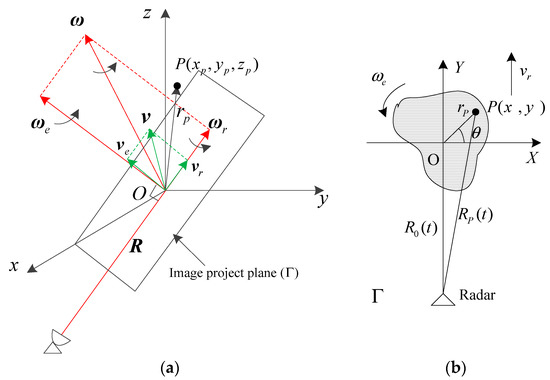
Figure 1.
Inverse synthetic aperture radar (ISAR) imaging geometry. (a) Three-dimensional (3D) imaging geometry and (b) two-dimensional (2D) turntable imaging geometry.
As can be seen from Figure 1a, the scattering point P is rotated by a linear velocity of ; its corresponding radial component is . Therefore, the instantaneous Doppler frequency of the scattering point P is:
where is the wavelength of the radar signal, and and represent the outer product and inner product of the vector, respectively. Since the ISAR imaging time is short, we assumed that the target imaging projection plane is approximately constant during the short imaging time, so the Doppler frequency of the scattering point P can be further expanded to:
where , , and are projected components of , , and on the three axes , respectively.
When a target is maneuvering, generally changes with time. Because the imaging time is short, the motion of the target can approximately change linearly with time [7], ignoring the influence of high-order components on the imaging, so we can obtain:
where and respectively represent the initial velocity and acceleration of the target, and respectively represent the angular velocity and angular acceleration of the decomposed along three coordinate axes, and is the azimuth time.
Combining Equations (2) and (3), the range from the scattering point P to the radar is:
where represents the range from the radar to the target origin O at the initial moment . , , and .
From Equation (4), for the maneuvering target, the instantaneous range exhibits a quadratic characteristic of the azimuth time, corresponding to the frequency modulation characteristic in the azimuth phase, which seriously affects the azimuth Doppler imaging.
In order to obtain a high-range resolution, a radar usually uses an ultra-bandwidth linear frequency modulation (LFM) signal. The expression of the transmitted signal is:
where , is the pulse width, is the carrier frequency, is the chirp-rate, is the range fast time, and is the azimuth slow time.
After the time delay , the radar receives the echo signal of the point P:
ISAR uses the “dechirp” reception mode to reduce the sampling rate of the echo signal. The reference signal is:
where , is the reference range. For ease of analysis, it is usually assumed that is satisfied. Therefore, the range compression signal after the dechirp processes compensates for the residual video phase (RVP) and the envelope skew term is [15]:
where .
It can be seen from Equation (8) that in the phase of the range compressed signal determines the azimuth focusing effect. The first and second terms cause envelope migration and need to be compensated for. The third term is necessary to achieve high-resolution azimuth imaging; the fourth term is due to azimuth defocusing caused by azimuth Doppler time-varying and needs to be compensated for. Therefore, envelope migration correction and azimuth focusing processing are needed to achieve high-resolution imaging. Envelope migration has been studied in many papers and achieved good results [24,25,26], and we will not go into detail in this paper. This paper focuses on azimuth focusing imaging.
Assuming that the target has completed envelope migration correction, the target scattering point is corrected in the corresponding range unit, and the range unit where the P point is located has N scattering points. The azimuth echo signal of the range unit can be expressed as:
where ,,. ,, and represent the amplitude, central frequency, and chirp-rate of the azimuth echo of the ith scattering point, respectively.
It can be seen from Equation (9) that the target azimuth echo signal is a multi-component LFM signal with different central frequencies and chirp rates due to the distribution of a plurality of scattering points having different lateral distances in the same range cell. Figure 2 is a time-frequency diagram of a certain range cell. Figure 2a depicts a pulse-range cell diagram after translation compensation of range compression; Figure 2b demonstrates the time-frequency transformation of the azimuth signal of the range cell where the black arrow is located. From the time-frequency diagram, it can be seen that the range cell signal is approximately a multi-component LFM signal.
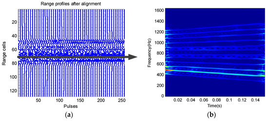
Figure 2.
Example of time-frequency diagram of a range cell. (a) Range profiles after alignment and (b) smooth pseudo Wigner-Ville distribution (SPWVD) of a range cell.
As shown in Figure 1b, suppose is the ith scattering point on the range cell, is the lateral distance of the imaging plane, and the effective rotational component can be expressed as angular velocity and angular acceleration in the imaging plane. Then, and . Therefore, the ratio of chirp rate to central frequency can be obtained:
It can be seen from the rotation ratio that the coefficient is only related to the rotation ratio of the target and is independent of the coordinates of the scattering point. Therefore, for the rigid body target, rotation ratios remain unchanged, and the rotation ratios of the sub-echo LFM signals of all scattering points are also the same. In turn, Equation (9) can be resolved as:
3. Imaging Algorithm Based on Modified Chirp Fourier Transform
3.1. Azimuth Fast Compression Based on MCFT
The chirp Fourier transform is a polar coordinate representation of the matched Fourier transform [27,28]. Since the transform kernel is a chirp function, it is a linear transform for the chirp signal. The chirp Fourier transform (CFT) of the signal is:
When the signal is a chirp signal as shown in Equation (9), its frequency-modulated Fourier transform is:
When , the signal is accumulatively added to reach the maximum value. On the contrary, when , there is a mutual cancellation of the signal integration and the corresponding amplitude is small. CFT is a linear transformation, so there is no cross-term problem. Therefore, the chirp Fourier transform is performed on the azimuth multi-component LFM signal, and a spike occurs at the corresponding position to achieve compression. However, CFT requires a complex two-dimensional parameter search, resulting in a large amount of computation, which greatly reduces the engineering practicality of the algorithm [29,30].
From the analysis in the previous section, the rotation ratio for the maneuvering target is a fixed value. If is known, we can redefine the modified chirp Fourier transform (MCFT) as:
Combining Equations (11) and (14) produces:
when , Equation (15) provides the maximum value. That is, if the rotation ratio is known, MCFT is only needed once to compress the azimuth echo signal, and no two-dimensional search transformation is needed. This greatly reduces the computational complexity of the algorithm and improves the applicability of the algorithm.
The discrete form of MCFT is:
where is the sampling point, is the number of sampling points, s(n) is the discrete sequence of signals, is the transform rotation factor and , and is the digital frequency.
Because the phase factor of Equation (16) contains terms, it can only be calculated by discrete Fourier transform. In order to improve its speed, Equation (16) can be written in matrix form:
where is the Hadamard product and:
For the matrix form shown in Equation (17), if the length of the data and the rotation ratio of the target are known, the phase function can be stored in advance, similar to the phase factor function in FFT calculation, so that fast MCFT calculation can be realized. We can further optimize the phase function.
In order to avoid the influence of strong and weak scattering points on the sub-signals of the same range cell, the windowing function can be used in MCFT. Without windowing the azimuth raw data, in the reconstructed ISAR image, high sidelobes appear next to the main peaks [3]. Thus, the windowing function should be applied to reduce the sidelobes at the cost of a slightly reduced resolution. Common Hamming windows can be used for this purpose, defined by:
where is the weighting coefficients of the Hamming window function and N is the length of the window, that is, the length of discrete azimuth data.
3.2. Coarse Rotation Ratio Estimation Based on DCFT
In Section 3.1, we showed that if is known, azimuth compression can be achieved with only one MCFT. However, the angular velocity and angular acceleration of the non-cooperative target are unknown. Therefore, the rotation ratio needs to be estimated. As demonstrated in the Section 2 analysis, the rotation ratio is also the ratio of the chirp rate of the sub-echo signal to the central frequency . Therefore, the rotation ratio can be estimated indirectly by estimating the chirp rate and the central frequency of the sub-echo LFM signal. Not directly estimating the target’s rotational parameters greatly reduces the difficulty of estimating the parameters. In Section 3.1, we showed that CFT is a linear transformation, which does not produce cross-terms for multi-component LFM signals and exhibits a strong anti-noise performance. Therefore, we can use CFT to estimate .
However, the direct discrete chirp Fourier transform (DCFT) has two stringent conditions: the discrete signal parameters must be integers and the signal length must be prime, otherwise the performance will decline sharply [31]. These two requirements are hard to satisfy in practice. Therefore, the revised DCFT is usually used [32], which is defined as:
where is the digital chirp rate. When calculating , we can use the fast Fourier transform: each time, is fixed and the discrete Fourier transform of is calculated, so that each row of can be obtained in turn.
For example, the parameters of a three-component LFM signal are shown in Table 1, where the signal form and parameter interpretation here are shown in Equation (9). The signal is transformed by DCFT, and the result is shown in Figure 3. From the MCDFT estimation result, the estimation accuracy is high and consistent with the set parameters.

Table 1.
Parameter values and estimated values of signals.
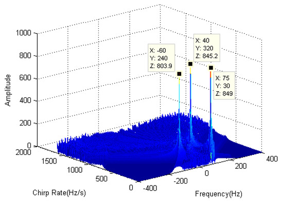
Figure 3.
Discrete chirp Fourier transform (DCFT) of three component LFM signals.
The central frequency and chirp rate of the LFM signal can be obtained by DCFT transformation, and the rotational parameters of the LFM signal can then be obtained. In practice, as there are many scattering points in the same range unit, a spectrum superposition of the DCFT spectrum may be produced, and estimation error easily occurs in peak detection based on the maximum amplitude criterion. In order to reduce the error between the estimated value and the true value , we can estimate the parameters of the sub-echoes of several scattering points in several different range cells and average the estimated values .
3.3. Accurate Rotation Ratio Estimation Based on Minimum Entropy
Whether or not the rotation ratio estimation is accurate directly affects the final imaging results. For this reason, we took the estimated value obtained by DCFT as the initial value, and then used the minimum Shannon entropy criterion of the spectral envelope for accurate estimation. The basis for this decision is that when the estimated value is closer to the true rotation ratio , the smaller the spectral broadening of each scattering point sub-echo, the higher the spectral envelope sharpening degree, and the smaller the Shannon entropy of the envelope. The relationship between envelope waveform entropy and the rotation ratio is shown in Figure 4. It can be seen from the figure that the change in image entropy is a convex function, and the optimal rotation ratio is obtained when the function takes the minimum value. Therefore, the solution of the rotation ratio can be regarded as the optimal solution problem, with the minimum entropy function as the objective function and as the variable. At present, there are many kinds of optimization methods available in machine learning and deep learning [33,34,35]. The simplest and most commonly used method is the gradient descent method [20,36], so we used this method to accurately estimate the rotation ratio.
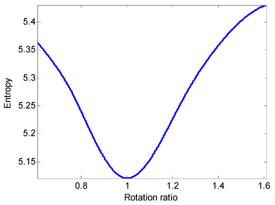
Figure 4.
The relationship between ISAR image entropy and rotation ratio.
Suppose that the rotation ratio is and the ith range cell spectral envelope obtained by DCFT in the form of Equation (16) is at the iteration. Then, the entropy of the ISAR image (objective function) is:
where represents the total number of azimuth sampling points.
The relationship between the objective function and the rotation ratio is:
where is the search step size and is the rough estimate obtained by the DCFT method. Suppose is the termination condition, where the iteration terminates when .
If is more accurate, a better azimuth image is obtained by the DCFT transform, a smaller entropy value is calculated by Equation (25), and the value in the graph is lower. The final estimate of the rotation ratio is:
After obtaining an accurate rotation ratio, azimuth signal focusing imaging can be accomplished by using MCFT transform once.
Summarizing the above analysis, we obtained a block diagram of the ISAR Imaging algorithm of maneuvering targets based on MCFT, as shown in the Figure 5. The specific steps are:
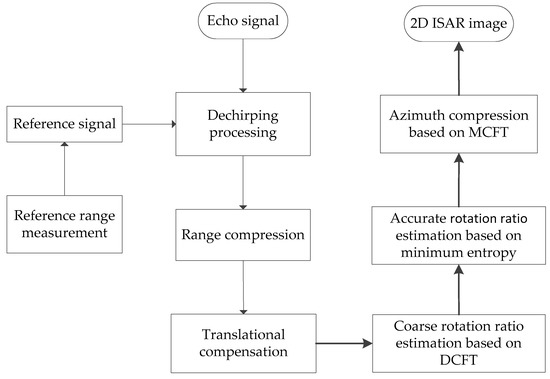
Figure 5.
ISAR Imaging algorithm for maneuvering targets based on discrete chirp Fourier transform.
- (1)
- Input the radar echo signal;
- (2)
- Generate reference signal by measured reference range;
- (3)
- Perform dechirping processing for the echo signal and reference signal;
- (4)
- Range compression and translational compensation for the signal after dechirping;
- (5)
- Coarse rotation ratio estimation based on DCFT in Section 3.2;
- (6)
- Accurate rotation ratio estimation based on minimum entropy in Section 3.3;
- (7)
- Azimuth compression based on MCFT in Section 3.1;
- (8)
- Output the two-dimensional (2D) ISAR image.
4. Simulation Experiment
In order to verify the effectiveness of the proposed method, a simulation and experimental verification were carried out.
4.1. Simulation Results
In the simulation experiment, an aircraft scattering point model with 74 points was adopted, as shown in Figure 6. The simulation radar parameters were as follows: the transmitting signal wavelength was 0.05 m, the signal carrier frequency was 6 GHz, the signal bandwidth was 400 MHz, the pulse repetition frequency (PRF) was 200 Hz, the pulse width was 25.6 ms, the number of range sampling points was 256, the number of transmitting pulses was 256, the sampling frequency was 10 MHz, and the imaging time was 1.28 s. The target rotated at a uniform acceleration, with a rotating angular velocity of 0.05 rad/s and a rotating angular acceleration of 0.05 rad/s2. The rotation ratio was . In order to express this clearly, radar parameters and target motion parameters are listed in Table 2.
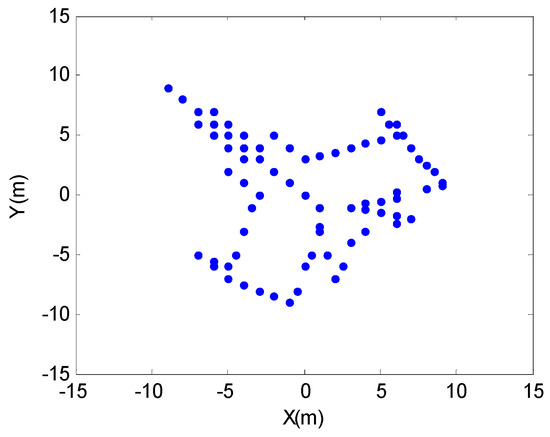
Figure 6.
Scattering point model for aircraft targets.

Table 2.
Simulation parameters.
Figure 7 shows the result of imaging the target directly using the RD algorithm, in which keystone transform is used to correct the cross-range unit migration [16]. It can be seen from the result that, for a maneuvering target, the RD algorithm causes serious defocusing in the azimuth direction, and the farther the scattering point from the reference center, the more serious the defocusing.
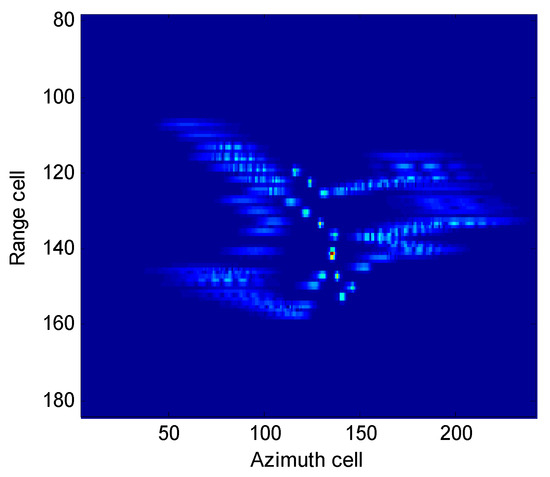
Figure 7.
Range Doppler (RD) imaging results.
DCFT was used to estimate the peak values of the 112th, 122th, 128th, and 133th range cells; the results are shown in Table 3. Figure 8 shows the MCDFT distribution diagram at the selected range cell. In the simulation, Gaussian noise was added, and the signal-to-noise ratio (SNR) was . By averaging the four estimated rotational coefficients, we obtained the average value of . This value is very close to the true value, , which shows that the parameter estimation method based on DCFT is effective.

Table 3.
Coarse rotation ratio estimation results.
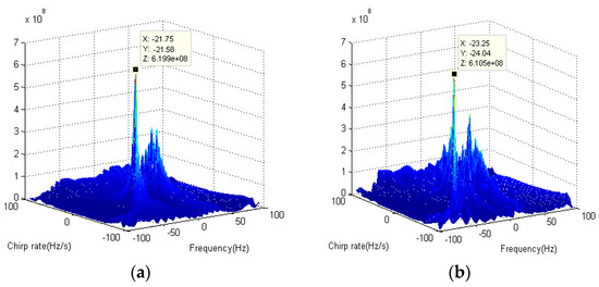
Figure 8.
MCDFT distribution diagram at the (a) 113th and (b) the 122th range cell.
Figure 9 shows the minimum waveform entropy function iteration process based on gradient descent. After 30 iterations, we determined the minimum entropy, and the optimal rotation ratio was found. Figure 10 is the MCFT imaging result based on the optimal rotation ratio proposed in this paper. The result shows that the scattering points are clearly visible. The algorithm achieved a better focusing effect and eliminated the azimuth defocusing phenomenon.
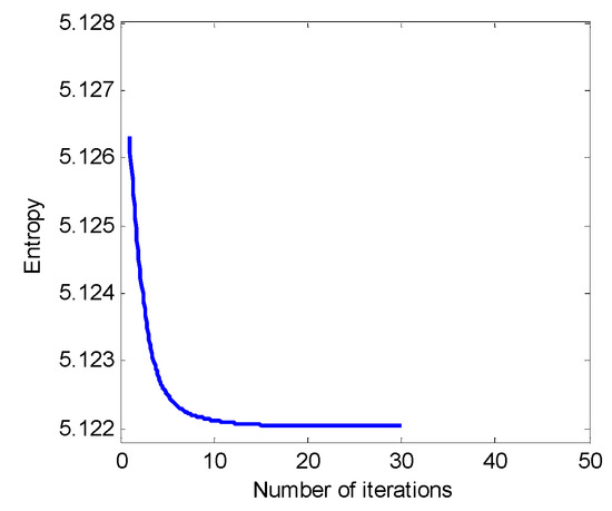
Figure 9.
Image entropy vs. iterations.
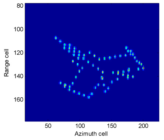
Figure 10.
The MCFT imaging result.
Figure 11 is the SPWVD-based time-frequency distribution diagram of the 113th range cell, and Figure 12 is the corresponding Doppler spectrum before and after the MCFT focus process. It can be seen from Figure 11a that the range cell is a multi-component LFM signal (actually a three-component signal) before the azimuth focusing. From the corresponding azimuth-compressed spectrum (Figure 12a), the azimuth produces Doppler diffusion, and the close scattering point Doppler component is smeared; thus, the focusing effect was not achieved. It can be seen from Figure 11b that after the MCFT azimuth focusing process, the range cell was adjusted to a multi-component single carrier frequency signal. From the corresponding azimuth Doppler spectrum (Figure 12b), the azimuth Doppler diffusion disappeared; all three targets can be separated in the Doppler domain.
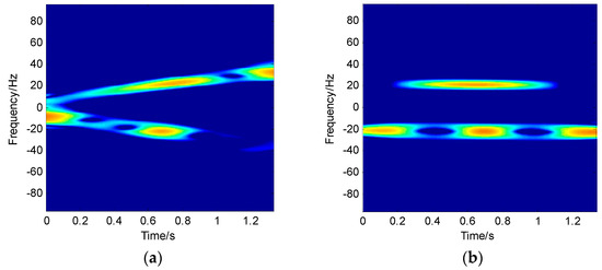
Figure 11.
The SPWVD of 113th range cell (a) before and (b) after the MCFT focus process.
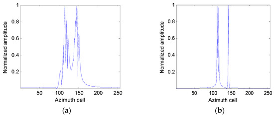
Figure 12.
The Doppler spectral at the 113th range cell (a) before and (b) after the focus process.
To illustrate the effectiveness of the proposed algorithm, the contrast imaging results of the several traditional algorithms are given in Figure 13. Figure 13a is the Radon-Wigner transform (RWT) imaging result, which shows that the RWT algorithm has a certain improvement effect on the azimuth focusing, but there is still defocusing and smearing. Figure 13b–d are the instantaneous imaging results using different time-frequency algorithms at t = 0.0851 s. Figure 13b is the STFT-based range instantaneous Doppler imaging result. The result shows that the imaging focusing effect is limited because the time-frequency resolution is affected by the window function. Figure 13d is the WVD-based range instantaneous Doppler imaging result, in which the WVD time-frequency resolution is better than STFT, but the azimuth echo is a multi-component signal, resulting in many cross-terms. The imaging results are so poor that the target cannot be identified. In order to suppress cross terms, windowing and smoothing operations are usually used for WVD (that is, SPWVD); the imaging result is shown in Figure 13d. The result shows that although the cross terms are effectively suppressed compared with WVD, the frequency resolution is reduced. Notably, the time-frequency method used in Figure 13b–d shows the azimuth Doppler variation with time and depicts the imaging results at different times. By comparing Figure 13 and Figure 10, the proposed algorithm achieves a demonstrably better azimuth focusing effect. In the traditional algorithm, RWT can improve the azimuth defocus to a certain extent, but the effect is general; the instantaneous imaging result depends on the time-frequency distribution algorithm used. It is usually difficult to balance both time-frequency resolution and cross-term terms.
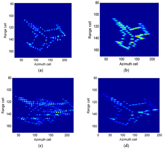
Figure 13.
Azimuth compression via classical methods. (a) Radon-Wigner transform (RWT), (b) short-time Fourier transform (STFT), (c) Wigner-Ville distribution (WVD), and (d) SPWVD.
In order to quantitatively evaluate the performance of the MCFT algorithm against other algorithms in terms of imaging quality, we used three common indicators: image entropy, contrast [20], and running time. We compared the algorithms proposed in Figure 10. The comparison results of the traditional algorithms mentioned in Figure 13 and the algorithm proposed in this paper are shown in Table 4. From the results, the MCFT algorithm has lower image entropy and larger image contrast values than the other algorithms, which shows that its image quality is better. In terms of running time, the MCFT algorithm requires more time than the RD and STFT algorithms, but less time than other algorithms, considering both imaging quality and imaging efficiency. The running time of MCFT consists of three parts: the coarse rotation ratio estimation by the DCFT method required 0.8558 s, the accurate rotation ratio estimation by the entropy method required 1.8248 s, and the MCFT imaging required 0.5541 s.

Table 4.
Comparison of simulation aircraft imaging results.
4.2. Experimental Results
In addition to the simulation data we generated, we also used the publicly available Boeing-727 data [22] from Victor C. Chen of the U.S. Naval Research Laboratory [37,38] and the Yak-42 measured data from Harbin Institute of Technology, China [39] to verify the performance of the proposed algorithm.
4.2.1. Boeing-727 Imaging Results
The Boeing-727 data included 256 successive pulses and the number of range cells per pulse was 64. The radar uses a stepped-frequency waveform, where the carrier frequency was 9.0 GHz, the bandwidth was 150 MHz, and the pulse repetition frequency was 25 KHz. Range compression and motion compensation for the data were completed. The range profile and the RD imaging result are shown in Figure 14. The target azimuth was seriously defocused due to the maneuvering motion of the target.
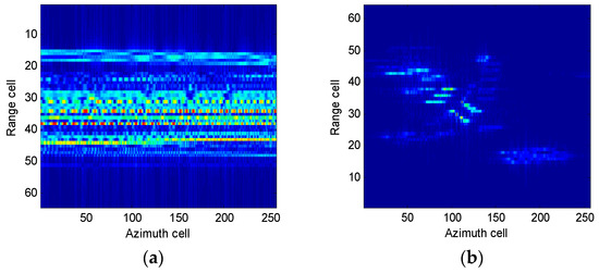
Figure 14.
Boeing-727 imaging results using (a) range profile and (b) RD imaging.
In order to eliminate the azimuth defocus, we used the MCFT algorithm proposed in this paper to image the Boeing-727 data. Figure 15a depicts a coarse estimate of the rotation ratio of the 33th range cell obtained using DCFT. The estimated value was . Figure 15b highlights the relationship between image entropy and the number of iterations by using the minimum entropy function. After 180 iterations, the minimum image entropy was obtained, and the corresponding exact rotation ratio was .
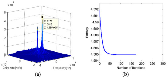
Figure 15.
Rotation ratio estimation for Boeing-727 data: (a) Course rotation ratio estimation and (b) RD imaging result.
Figure 16 shows the imaging results using the MCFT method proposed in this paper and several contrast methods. The evaluation indexes of each imaging result are shown in Table 5. It can be seen from Figure 16a that the proposed algorithm effectively eliminated azimuth defocusing. Figure 16b,c are the results of range instantaneous Doppler (RID) imaging using SFTT and SPWVD, respectively. The results are consistent with the analysis in the previous section. The time-frequency resolution of STFT was relatively poor and SPWVD exhibited an improved resolution. The advantage of the RID imaging method is that it can show the dynamic change in the imaging result with the orientation Doppler. The disadvantage is that the imaging result may lack scattering points at different moments. Figure 16d shows that the RWT algorithm also improved the azimuth focusing effect, but there is still partial defocusing. From the corresponding evaluation index in Table 5, we can see that the minimum entropy and contrast of the proposed MCFT algorithm are optimal. For running time, the RD and STFT can use FFT, so the computation time is shorter. Compared with RWT, which uses the same parameter estimation method, the computation time of the MCFT algorithm is much shorter. Combined with image results and evaluation indicators, the MCFT algorithm proposed in this paper is effective.
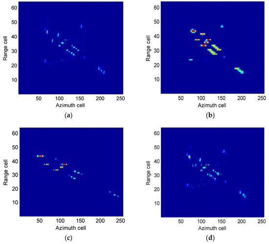
Figure 16.
Imaging results of Boeing-727 data using the (a) MCFT, (b) STFT, (c) SPWVD, and (d) RWT algorithm.

Table 5.
Comparison results of the Boeing-727 images.
4.2.2. Yak-42 Imaging Results
The selected Yak-42 data includes 256 pulses, with each containing a 256 range cell. The other parameters are: the radar transmits a chirp signal, the carrier frequency is 5520 MHz, the bandwidth is 400 MHz, the pulse repetition frequency is 400 Hz, and the pulse width is 25.6 μs. Range compression and motion compensation for the data have been completed. The range profile and the imaging results using different imaging algorithms are shown in Figure 17, and Table 6 provides the corresponding imaging evaluation indicators. Figure 17a is the range profile and Figure 17b is the RD imaging results, which shows that the RD algorithm could not eliminate the azimuth defocus caused by maneuvering because the RD algorithm only uses FFT calculation. The corresponding image entropy and contrast were also poor, but the running time was the shortest. Figure 17c depicts the result of the MCFT imaging proposed in this paper. The result shows that azimuth defocusing was effectively improved, the scattering point of the target was clear, and the corresponding image entropy and contrast were optimal. Figure 17d is the result of RWT imaging, and the result shows that the azimuth defocusing was partially improved, but the degree of improvement was general. The corresponding image entropy and contrast also prove this point, and the algorithm ran for a long time. Figure 17e,f are the RID imaging results based on STFT and SPWVD, respectively. From the results, it can be seen that the effect of STFT and SPWVD on the measured data was poor. In the MCFT algorithm, the estimated coarse rotation ratio was , the cut-off condition was reached after 150 iterations, and the corresponding precise rotation ratio was . From the running time in Table 6, the proposed algorithm was highly efficient for the measured data.
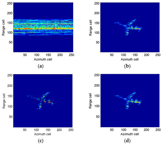
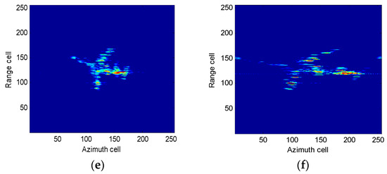
Figure 17.
Imaging results of Yak-42 data: (a) Range profile, (b) RD algorithm, (c) MCFT algorithm, (d) RWT algorithm, (e) STFT-RID algorithm, and (f) SPWVD-RID algorithm.

Table 6.
Comparison results of the Yak-42 images.
5. Conclusions
Inverse synthetic aperture radar achieves the high-resolution imaging of non-cooperative targets, but maneuvering leads to the change in radar azimuth echo Doppler with time, which complicates azimuth imaging processing. In order to solve this problem, a modified chirp Fourier transform imaging method was proposed in this paper. By using the inherent relationship between the target rotation parameter and the radar echo parameter, meaning the ratio of the target rotational angular acceleration to the rotational angular velocity is fixed and the ratio is equal to the ratio of the chirp rate to the center frequency of the radar echo signal, fast focusing target imaging was realized. This method uses DCFT to quickly estimate the coarse rotation ratio; then, under the minimum image entropy principle, the accurate rotation ratio is obtained using the gradient descent method. The image entropy obtained by this method is the smallest, realizes the best evaluation results, avoids the estimation and separation of the sub-echo components, and considerably improves the imaging speed. The simulation and measured data also prove that the proposed method effectively performs two-dimensional, high-resolution, and fast imaging of maneuvering targets.
Author Contributions
Y.L. and L.Q. conceived and designed the method; Y.W. (Yanhong Wu) guided the students to complete the research; Y.L. performed the simulation and experiment tests; Y.W. (Yongping Wang), H.W., H.Z., and Y.S. helped in the simulation and experiment tests; and Y.L. wrote the paper.
Funding
The authors are grateful for the financial support received from the State 863 Project of China (No. 2014AA7113016) and the Research Project of the State Key Laboratory of Complex Electromagnetic Environment Effects on Electronics and Information Systems (No. 2017Z0203B).
Conflicts of Interest
The authors declare no conflict of interest.
References
- Ruan, H.; Wu, Y.; Jia, X. Novel ISAR imaging algorithm for maneuvering targets based on a modified keystone transform. IEEE Geosci. Remote Sens. Lett. 2014, 11, 128–132. [Google Scholar] [CrossRef]
- Lazarov, A.; Minchev, C. ISAR geometry, signal model, and image processing algorithms. IET Radar Sonar Navig. 2017, 11, 1425–1434. [Google Scholar] [CrossRef]
- Chen, V.C.; Martorella, M. Introduction to ISAR imaging. In Inverse Synthetic Aperture Radar Imaging Principles, Algorithms and Applications; SciTech Publishing: Edison, NJ, USA, 2014; pp. 1–19. [Google Scholar]
- Liu, Y.; Xing, M.; Zhang, L.; Sheng, J.; Li, Y.; Bao, Z. Novel range profile synthesis algorithm for linearly stepped-frequency modulated inversed synthetic aperture radar imaging of remote manoeuvring target. IET Radar Sonar Navig. 2011, 5, 496–506. [Google Scholar] [CrossRef]
- Li, G.; Zhang, H.; Wang, X.Q.; Xia, X.G. ISAR 2-D imaging of uniformly rotating targets via matching pursuit. IEEE Trans. Aerosp. Electron. Syst. 2012, 48, 1838–1846. [Google Scholar] [CrossRef]
- Wang, Y.; Ling, H.; Chen, V.C. ISAR motion compensation via adaptive joint time-frequency technique. IEEE Trans. Aerosp. Electron. Syst. 1998, 34, 670–677. [Google Scholar] [CrossRef]
- Lv, X.L.; Xing, M.D.; Wan, C.R.; Zhang, S. ISAR imaging of maneuvering targets based on the range centroid Doppler technique. IEEE Trans. Image Process. 2010, 19, 141–153. [Google Scholar] [PubMed]
- Wang, Y.; Jiang, Y.C. ISAR imaging of maneuvering target based on the L-Class of fourth-order complex-lag PWVD. IEEE Trans. Geosci. Remote Sens. 2010, 48, 1518–1527. [Google Scholar] [CrossRef]
- Bao, Z.; Wang, G.Y.; Luo, L. Range-instantaneous Doppler imaging in ISAR. ACTA Electron. Sin. 1998, 26, 79–82. [Google Scholar]
- Li, W.C.; Wang, X.S.; Wang, G.Y. Scaled radon-Wigner transform imaging and scaling of maneuvering target. IEEE Trans. Aerosp. Electron. Syst. 2010, 46, 2043–2051. [Google Scholar] [CrossRef]
- Fu, Y.W.; Hu, J.M.; Li, X. ISAR imaging of uniformly accelerative rotating targets based on chirp-Fourier transform. Syst. Eng. Electron. 2011, 33, 2608–2612. [Google Scholar]
- Wu, L.; Wei, X.; Yang, D.; Wang, H.; Li, X. ISAR Imaging of targets with complex motion based on discrete chirp Fourier transform for cubic chirps. IEEE Trans. Geosci. Remote Sens. 2012, 50, 4201–4212. [Google Scholar] [CrossRef]
- Wang, G.; Bao, Z. Inverse synthetic aperture radar imaging of maneuvering targets based on chirplet decomposition. Opt. Eng. 1999, 38, 1534–1541. [Google Scholar] [CrossRef]
- Wang, Y.; Jiang, Y.C. ISAR imaging of a ship target using product high order matched-phase transform. IEEE Geosci. Remote Sens. Lett. 2009, 6, 658–661. [Google Scholar] [CrossRef]
- Li, Y.; Wu, R.; Xing, M.D.; Bao, Z. Inverse synthetic aperture radar imaging of ship target with complex motion. IET Radar Sonar Navig. 2008, 2, 395–403. [Google Scholar] [CrossRef]
- Wang, Y.; Jiang, Y.C. Inverse synthetic aperture radar imaging of maneuvering target based on the product generalized cubic phase function. IEEE Geosci. Remote Sens. Lett. 2011, 8, 958–962. [Google Scholar] [CrossRef]
- Peng, S.B.; Xu, J.; Peng, Y.N.; Xiang, J.B. Parametric inverse synthetic aperture radar manoeuvring target motion compensation based on particle swarm optimiser. IET Radar Sonar Navig. 2011, 5, 305–314. [Google Scholar] [CrossRef]
- Noviello, C.; Fornaro, G.; Braca, P.; Martorella, M. Fast and Accurate ISAR Focusing Based on a Doppler Parameter Estimation Algorithm. IEEE Geosci. Remote Sens. Lett. 2016, 99. [Google Scholar] [CrossRef]
- Wang, B.; Xu, S.; Wu, W.; Hu, P.; Chen, Z. Adaptive ISAR imaging of maneuvering targets based on a modified Fourier transform. Sensors 2018, 18, 1370. [Google Scholar] [CrossRef]
- Wang, Y.; Zhao, B.; Jiang, Y. Inverse synthetic aperture radar imaging of targets with complex motion based on cubic Chirplet decomposition. LET Signal Process. 2015, 9, 419–429. [Google Scholar] [CrossRef]
- Li, Y.; Fu, Y.; Zhang, W. Distributed ISAR Subimage Fusion of Nonuniform Rotating Target Based on Matching Fourier Transform. Sensors 2018, 18, 1806. [Google Scholar] [CrossRef]
- Wu, W.; Xu, S.; Hu, P.; Zou, J.; Chen, Z. Inverse Synthetic Aperture Radar Imaging of Targets with Complex Motion based on Optimized Non-Uniform Rotation Transform. Remote Sens. 2018, 10, 593. [Google Scholar] [CrossRef]
- Lv, Y.; Wu, Y.; Wang, H.; Qiu, L.; Jiang, J.; Sun, Y. An Inverse Synthetic Aperture Ladar Imaging Algorithm of Maneuvering Target Based on Integral Cubic Phase Function-Fractional Fourier Transform. Electronics 2018, 7, 148. [Google Scholar] [CrossRef]
- Liu, L.; Zhou, F.; Tao, M.; Sun, P.; Zhang, Z. Adaptive Translational Motion Compensation Method for ISAR Imaging Under Low SNR Based on Particle Swarm Optimization. IEEE J. Sel. Top. Appl. Earth Obs. Remote Sens. 2015, 8, 5146–5157. [Google Scholar] [CrossRef]
- Li, D.; Zhan, M.; Liu, H.; Liao, Y.; Liao, G. A Robust Translational Motion Compensation Method for ISAR Imaging Based on Keystone Transform and Fractional Fourier Transform under Low SNR Environment. IEEE Trans. Aerosp. Electron. Syst. 2017, 53, 2140–2156. [Google Scholar] [CrossRef]
- Wu, H.; Grenier, D.; Delisle, G.Y.; Fang, D.G. Translational motion compensation in ISAR image processing. IEEE Trans. Image Process. 1995, 4, 1561–1571. [Google Scholar] [PubMed]
- Guo, X.; Sun, H.B.; Wang, S.L.; Liu, G.S. Comments on discrete chirp-Fourier transform and its application to chirp rate estimation [with reply]. IEEE Trans. Signal Process. 2002, 50, 3115–3116. [Google Scholar]
- Jiang, M.; Zhang, Y. ISAR Imaging Based on Frequency Modulated Fourier Transform in Low SNR Environment. J. Proj. Rockets Missiles Guid. 2017, 2, 129–134. [Google Scholar]
- Wang, C.; Wang, Y.; Li, S.B. Inverse synthetic aperture radar imaging of ship targets with complex motion based on match Fourier transform for cubic chirps mode. IET Radar Sonar Navig. 2013, 7, 994–1003. [Google Scholar]
- Fan, P.; Xia, X. Two modified discrete chirp Fourier transform schemes. Sci. China 2001, 44, 329–341. [Google Scholar]
- Zhan, L.; Tang, Z.; Zhu, Z. Keystone transform and MDCFT-based detection and parameter estimation for maneuvering weak targets. Acta Aeronaut. Astronaut. Sin. 2013, 34, 855–863. [Google Scholar]
- Yang, P.; Liu, Z.; Jiang, W.L. Parameter estimation of multi-component chirp signals based on discrete chirp Fourier transform and population Monte Carlo. Signal Image Video Process. 2015, 9, 1137–1149. [Google Scholar] [CrossRef]
- Huang, G.B.; Ding, X.; Zhou, H. Optimization method based extreme learning machine for classification. Neurocomputing 2010, 74, 155–163. [Google Scholar] [CrossRef]
- Goodfellow, I.; Bengio, Y.; Courville, A. Deep Learning; The MIT Press: Cambridge, MA, USA, 2016; pp. 169–199. [Google Scholar]
- Yonel, B.; Mason, E.; Yazici, B. Deep Learning for Passive Synthetic Aperture Radar. IEEE J. Sel. Top. Signal Process. 2018, 12, 90–103. [Google Scholar] [CrossRef]
- Alakkari, S.; Jamil, K.; Alhumaidi, S. Range only target localization in multi-static passive radar system: A gradient descent approach. In Proceedings of the 2015 Signal Processing Symposium (SPSympo), Debe, Poland, 10–12 June 2015; pp. 1–4. [Google Scholar]
- Chen, V.C. Doppler signatures of radar backscattering from objects with micro-motions. IET Signal Process. 2008, 2, 291–300. [Google Scholar] [CrossRef]
- B727S.mat. Available online: http://www.mdpi.com/2072-4292/10/4/593/s1 (accessed on 12 October 2018).
- Wang, Y.; Kang, J.; Jiang, Y.C. ISAR imaging of maneuvering target based on the local polynomial Wigner distribution and integrated high order ambiguity function for cubic phase signal model. Remote Sens. 2014, 7, 2971–2991. [Google Scholar] [CrossRef]
© 2018 by the authors. Licensee MDPI, Basel, Switzerland. This article is an open access article distributed under the terms and conditions of the Creative Commons Attribution (CC BY) license (http://creativecommons.org/licenses/by/4.0/).