1. Introduction
It is known that the minimum-time optical response is achieved in some smectic liquid crystals, called smectics C*, which possess ferroelectric properties and high sensitivity to electric fields [
1,
2,
3]. The principle of electro-optical modulation in ferroelectric liquid crystals (FLCs), like in widely used nematic liquid crystals (NLCs), is the electrically controlled birefringence or light scattering.
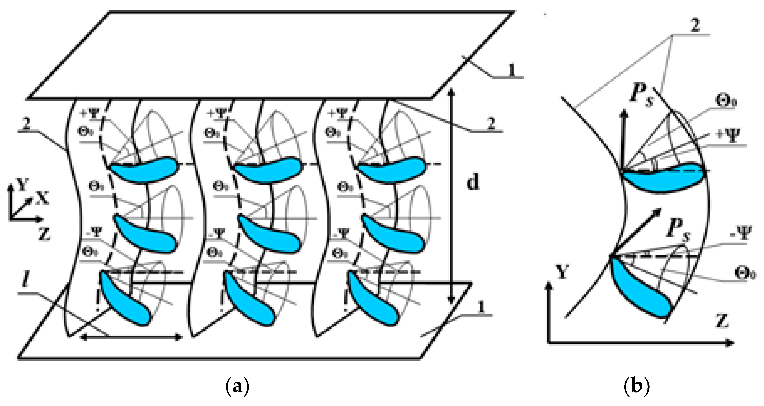
A distinctive feature of smectic crystals is the layered structure formed as a result of ordering the centers of mass of FLC molecules along the direction of orientation of their long axis (director), with a pitch of the order of the molecules’ length. Among the smectic crystals, the helix FLCs are the most well known, in which the polar axes of various smectic layers are rotated relative to each other, forming a helix (spiral) twist of the FLC director in the absence of an external electric field (
Figure 1). In each layer, the position of the director
n is determined by the polar angle
Θ0 and the azimuth angle
φ, which varies from 0 to 2
π at a distance equal to the pitch
p0 of the helix. Under the action of the electric field
E, which is parallel to smectic layers (along the coordinate
x), the vector
PS of spontaneous polarization is oriented in all layers along the field direction. As a result, the director acquires one direction in the entire volume of the FLC layer—the direction of the FLC main optical axis.
When a sign of the field
E changes, the orientation of the vector
PS changes by 180°, and the long axes of molecules unfold along the cone with the generatrix 2
Θ0, resulting in a change of the angle
φ by 180°. The reorientation of the director determining the main optical axis of the ellipsoid of the FLC refractive indices results in a change in the angle between the polarization plane of the incident light (
I0) and the main optical axis of the ellipsoid. This leads to the modulation of the phase delay between the ordinary and extraordinary rays, or to light intensity modulation, if the electro-optic cell is placed between crossed polarizers [
1,
2,
3]. Under certain conditions, electrically controlled light scattering on so-called transient domains is observed in the helix FLC due to the formation of a spatially inhomogeneous structure of refractive index gradients in the FLC layer [
4,
5].
Helix-free (no spiral) FLCs are also known [
6]. In them, the helicoidal twist of the director in the FLC volume is compensated or suppressed by the interaction of chiral optically active additives with opposite signs of optical activity. The coincidence of the same signs of spontaneous polarization in chiral additives makes it possible to obtain a value of spontaneous polarization of 100 nC/cm
2 or higher for FLCs with a compensated helicoid.
In contrast to NLC, the electro-optical effect in FLC is linear relative to the field [
7,
8], and since FLC reacts to the sign of the applied electric voltage, the values of the on and off times of the optical response are the same and are proportional to
if the dissipative coefficient is the rotational viscosity
γφ. The FLC is returned to its original state by a reverse-polarity pulse, i.e., forcedly, not as a result of relaxation due to elastic forces (like in the NLC). Therefore, the optical response at switching on and off is symmetrical and very short (in the sub-millisecond region), especially for FLC with low viscosity and large spontaneous polarization. However, it is impossible to significantly reduce
τR by increasing the spontaneous polarization, since this usually leads to an increase in the FLC rotational viscosity. This circumstance limits the frequency of light modulation if the applied voltage does not exceed several volts.
In the research carried out at the Lebedev Physical Institute (LPI), it was shown that the nature of the FLC director reorientation in an electric field depends essentially on the coefficient responsible for the energy dissipation in an FLC layer: the rotational or shear viscosity [
9]. If the alternating electric field of the frequency
f acts on the FLC, and the period of its variation is large (
τm·f << 1) in comparison with the Maxwellian relaxation time
τm [
10], then the FLC behaves as a liquid with the viscosity
γφ. On the contrary, at sufficiently high frequencies (
τm·f >> 1), the FLC behaves as an amorphous solid, and the dissipative coefficient is the shear viscosity (denoted
γψ).
The predominance of shear viscosity leads to a change in the character of the motion of the helix FLC director in weak electric fields: the reorientation occurs due to the motion of 180°-domain walls [
9,
11,
12]. Such a reorientation process made it possible to obtain a modulation frequency of light radiation of the order of 3 kHz with an electric field strength of about 1 V/μm. The time of the electro-optical response was 50 ÷ 70 μs. As a disadvantage, some distortion of the spectral composition of the modulated radiation and the residual light scattering caused by the presence of a helix was noted.
The character of the electric field action is practically the same for known helix-free FLCs. In them, the azimuth angle
φ of the director’s orientation in the volume of a layer is a value that is practically constant in all smectic layers; i.e., there is a so-called spatially homogeneous structure. The magnitude of the spontaneous polarization is much higher than 50 nC/cm
2. The dissipative coefficient is the rotational viscosity
γφ, and the director reorientation time, as for the helix FLC, does not depend on the frequency of the electric field change [
8].
A new type of helix-free FLC specially developed at the LPI has a different character of interaction with the electric field. This material is a spatially inhomogeneous structure with periodic deformation of smectic layers (with a pitch from 1.5 to 5 μm) in the absence of an electric field and a relatively small value of spontaneous polarization (less than 50 nC/cm
2). In such an FLC, the director reorientation in the alternating electric field is due to the motion of structurally stable localized waves of a stationary profile—dynamic solitons that arise upon the transition to the Maxwellian mechanism of energy dissipation—and the electro-optical response depends essentially on the frequency of the electric field change [
13,
14,
15,
16]. Note that a director reorientation through solitons was proposed for the first time in [
17].
The new materials provided unique parameters of radiation modulation unattainable for LC analogs. For example, in a transparent mode, in an electric field of the order of 1 V/μm (at a control voltage of ±1.5 V), experimental samples of electro-optical cells with the novel helix-free FLC show a modulation characteristic with the fastest optical response (about 25 microseconds) and the highest modulation frequency (up to 7 kHz), including hysteresis-free characteristics with a continuous gray scale up to 6 kHz. In a bistable light-scattering mode, a state with intensive scattering can be turned on and off for a few tens of microseconds and be memorized for several tens of seconds or until a pulse of opposite polarity appears [
16].
We will now consider in more detail the physical properties, light modulation characteristics, and possible applications of the new helix-free FLC based on the results attained from our research during the last few years.
2. Ferroelectric Liquid Crystals Compositions Used and Their Basic Properties
The basis of the new FLCs is the same optically active additives used in known FLC and based on derivatives of terphenyl-dicarboxylic acid. The difference is only in the specific compositions of FLCs, which is the object of know-how. In spite of the great difference in the rotational viscosity coefficient
γφ, which in various compositions changes by practically an order of magnitude (from 0.15 to 1.5 P), and in spite of the manifestation of essentially different optical properties (to be discussed below), the values of the spontaneous polarization
PS, the initial tilt angle of molecules in smectic layers
Θ0, and the sequence of phase transitions for all new FLCs differ insignificantly (see
Table 1).
The sequence of phase transitions for these compositions is the following:
Here, Cr is the crystalline phase, Sm C* is the chiral smectic C phase (ferroelectric), Sm A* is the chiral smectic A phase (paraelectric), and I is the isotropic (liquid) phase.
The new helix-free FLC materials exhibit the following basic properties in electro-optical cells, first discovered and investigated at the LPI:
A periodic spatial deformation of FLC smectic layers with a pitch of 1.5÷6 μm is observed in the absence of an electric field;
The FLC director is reoriented as a result of the soliton waves motion;
Certain FLC compositions show the fastest (among all LCs) optical response in a transparent mode with continuous gray scale;
Certain FLC compositions show the fastest (among all LCs) optical response in the light-scattering mode with data storage;
Certain FLC compositions provide a rapid change in the phase delay of the modulated radiation initiated by light scattering.
4. Ferroelectric Liquid Crystals Director Reorientation by an Electric Field in the Soliton Mode
As shown in [
15,
16], the periodic deformation of smectic layers means that for FLC molecules initially inclined at the angle
Θ0 with respect to the normal to the FLC layer at a given point, it is energetically preferable to additionally deflect by some angle ±
Ψ with respect to the direction
z of substrate rubbing (
Figure 3). Because of this, the position of the FLC main optical axis along the smectic layers changes, and the birefringence depends on the electric field frequency.
The electric field Е applied along the coordinate y interacts with the spontaneous polarization and changes the director distribution (the angle Ψ) in each smectic layer. The reorientation of the FLC director can occur both with the change of the azimuthal angle φ of the director orientation by 180°, when the director is reoriented along the cone generatrix with its 2Θ0 turn, and with the change in the distribution of the angle ψ characterizing the deformation of smectic layers. In the first case, the dissipative coefficient is the rotational viscosity γφ, and in the second case, it is the viscosity for the shear deformation γψ.
When after the electric field is turned off the director relaxation time begins to depend on the electric field frequency, the transition to the Maxwellian mechanism of energy dissipation takes place—that is, the transition from the rotation viscosity γφ to the shear viscosity γψ.
To describe the nonlinear dynamic process of FLC director reorientation in an external electric field, we used the soliton approach [
15,
16,
17,
18] by which many nonlinear effects and processes have been described before, including those in ferroelectric liquid crystals [
17,
19,
20,
21].
The soliton mode manifests in the new FLC compositions possessing coefficients of rotational viscosity in the range from 0.15 to 1 P, when the electric field frequency or, simultaneously, the frequency and the strength increase. At frequencies corresponding to the transition to the Maxwellian mechanism of energy dissipation, the viscosity γψ for the shear strain becomes a dissipative coefficient, and the dynamic solitons move along the smectic layers. The director of the FLC is reoriented by the motion of soliton waves.
The appearance of the soliton waves is due to the joint influence of the medium nonlinearity and the presence of a dispersion of velocities of deformation waves (or displacements). They sharply increase the steepness of the wave front and cause the growth of gradients of the field variables. This leads to a spatial redistribution of the excitation energy and its localization (the wave period tends to infinity). The shape of dynamic solitons is uniquely related to the independent parameters—in particular, to the velocity of the soliton center [
18]:
where
K is the FLC elastic modulus describing the deformation of the director with respect to the angle
Ψ;
γψ is the shear viscosity;
M is the bending energy of smectic layers; and
φ0 is the initial azimuth angle of the director orientation.
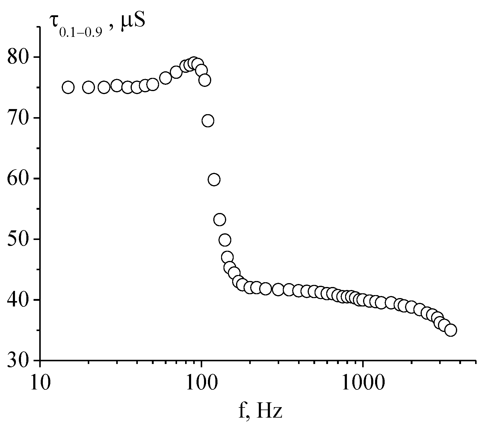
The transition to the Maxwellian mechanism of energy dissipation and the soliton mechanism of director reorientation is accompanied by a strong frequency dependence of the electro-optical response time
τ0.1–0.9. It can be seen from
Figure 4 that in the frequency range from 100 to 200 Hz, this time for the composition HF-32B with
γφ = 0.7 P decreases by almost half.
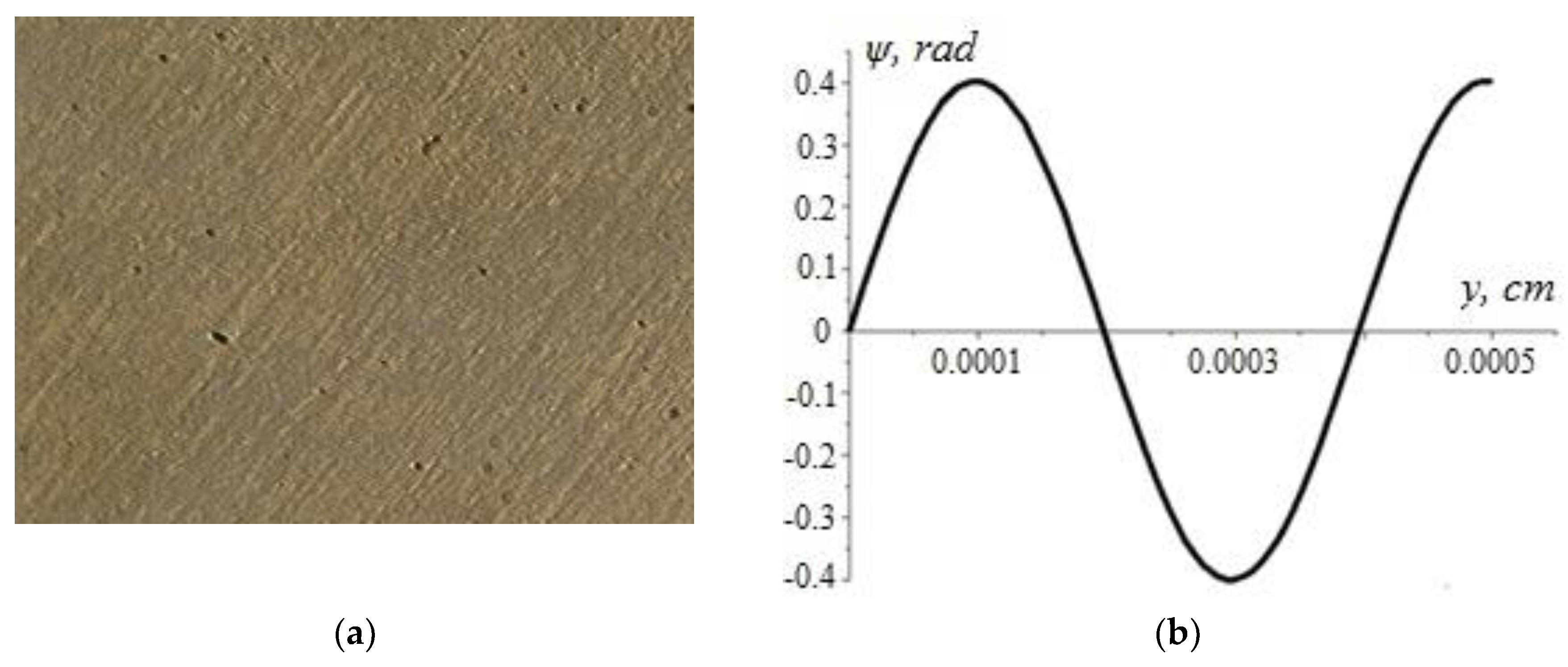
For more viscous FLC compositions, for example, for HF-32E with
γφ = 1.5 Poise, the frequency dependence of the electro-optical response time
τ0.1–0.9 is significantly weakened (
Figure 5a). The reason for this weakening is that the relaxation time of the FLC director to the unperturbed state after the voltage turning off is practically independent of the frequency of the electric field change (
Figure 5b). Consequently, the transition to the Maxwellian mechanism of energy dissipation does not occur, and the soliton mode does not manifest.
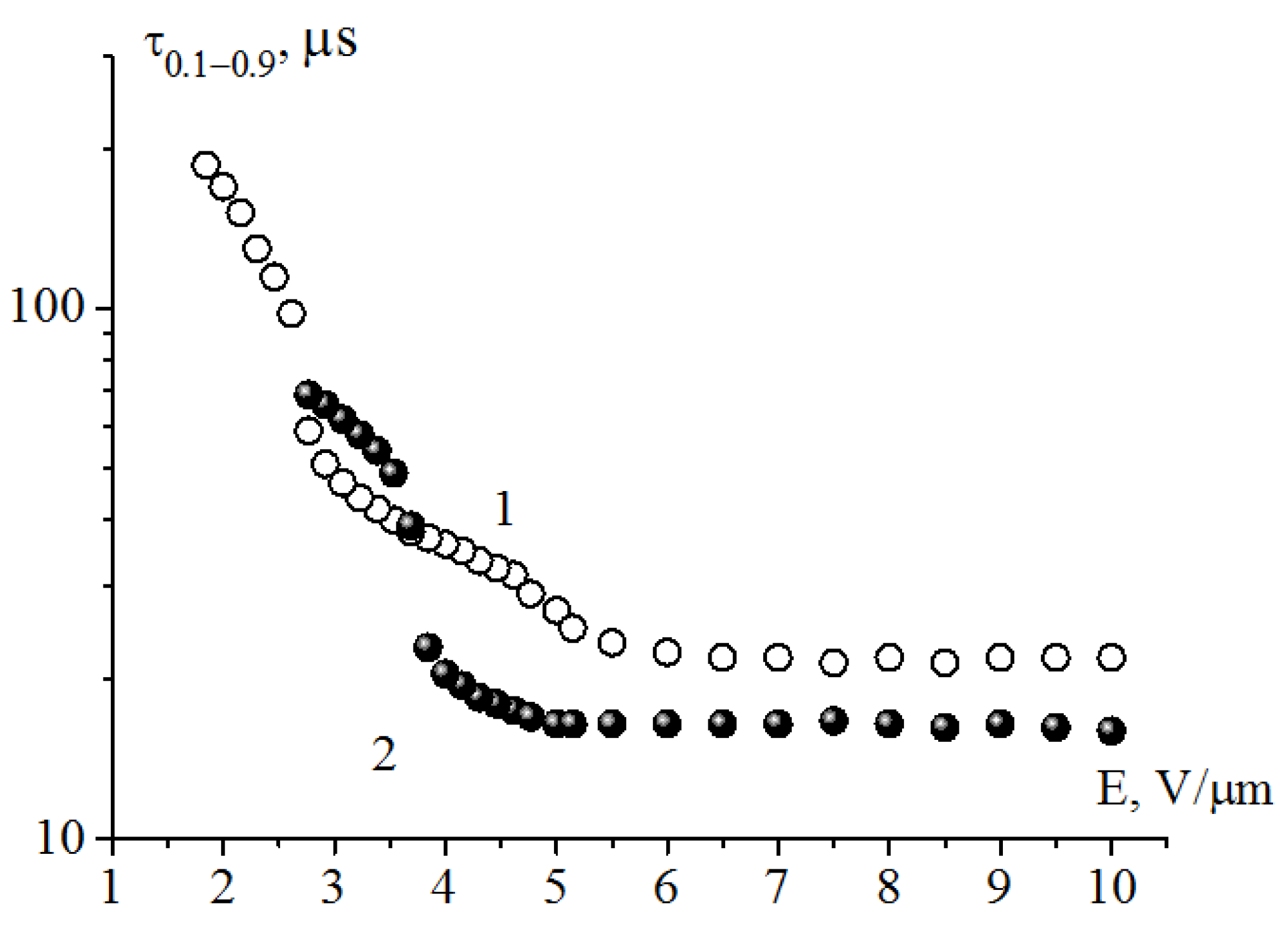
A decrease in the rotational viscosity coefficient to 0.15 Poise (for the composition HF-32D with practically the same spontaneous polarization value) leads to the soliton mode not being observed at the control voltage amplitude ±1.5 V (
Figure 6, curve 1). The soliton mode appears when the electric field strength exceeds 5 V/μm (
Figure 6, curve 2). This is especially seen in the frequency range of a few hundred Hz, when the transition to the mechanism of energy dissipation takes place.
6. Light Modulation in an Electro-Optic Cell with Helix-Free Ferroelectric Liquid Crystal (Experimental Results)
6.1. Modulation of Light Transmission
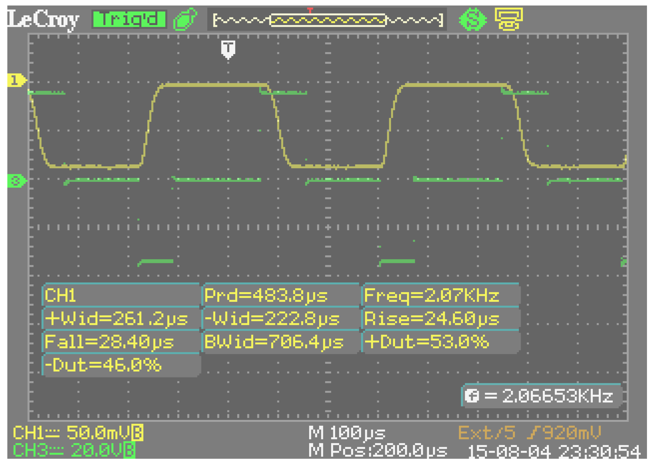
The modulation of light transmission was observed when an electro-optic cell of 1.7 μm thickness (achromatic for visible light) was placed between crossed polarizers and bipolar voltage of the rectangular shape (meander) was applied. The FLC director reorientation due to motion of solitons made it possible to reduce the optical response time in weak fields to 25 μs and to reach the light modulation frequency of 7 kHz at the control voltage of ±1.5 V [
3] (
Figure 8).
The transition to the soliton mode can occur not only with increasing frequency of the electric field change, but also with increasing field strength at fixed frequency. This transition is accompanied by a sharp decrease in the optical response time when a certain threshold value of the field strength is reached (
Figure 9). With increasing frequency, the threshold value of the field for the transition to the soliton mode decreases, and the time of the optical response
τ0.1–0.9 decreases (
Figure 9, curve 2) at a lower frequency.
After the transition to the soliton mode, a section in the dependence
τ0.1–0.9 (
Е) appears where the optical response time is independent of the electric field strength (
Figure 9). This means that the FLC dissipative coefficient is the shear viscosity.
Constant change in the director position along the FLC smectic layers provides the substantially hysteresis-free dependence of the light transmission of the electro-optical cell on the control voltage amplitude when both increasing and decreasing in a wide frequency range. Experiments have shown that the hysteresis-free modulation characteristic I (V) for both positive and negative voltage occurs if the following two conditions are satisfied: First, the frequency control voltage corresponds to the frequency interval of existence of the soliton mode (for the HF-32C composition, it extends from 100 Hz to 7 kHz). Second, this frequency does not correspond to the static portions (
Figure 10) of the frequency dependence of the FLC birefringence Δ
n (f). This means that the frequency of the hysteresis-free modulation does not exceed 6 kHz (
Figure 11). This maximum value was realized experimentally [
25].
Note that the halftone modulation characteristic in such a uniquely wide frequency range is realized only on the basis of the physical properties of new FLC materials. In addition, unlike the bistable (two-level) characteristic of the known FLCs, possible applications of novel helix-free FLC do not require additional electronic modulation of a signal, which reduces the frame rate of color image formation.
It is important that the predominance of shear viscosity in a soliton mode results in weakening the temperature dependence of the electro-optical response time in a wide temperature interval (
Figure 12). The higher the frequency of light modulation (and the frequency of the control voltage), the wider the temperature interval in which the time
τ0.1–0.9 is almost constant. It shifts to both high and low temperatures, and for the HF-32C composition, the time
τ0.1–0.9 at the maximum possible light modulation frequency of 7 kHz is from 10 to 52 °C.
The experimental results show that new helix-free FLCs are very promising materials for the next generation of LC displays, especially for fast displays using FLC on Silicon and 3D technologies, as well as the progressive Field Sequential Colors (FSC) technique, which allows us to form brighter images (because of the absence of RGB filters) by a display with a 3-times-smaller number of pixels [
26,
27].
6.2. Modulation of Light Scattering
The deformation of a single-domain structure of the FLC caused by a pulse of the electric field can be accompanied under certain conditions by a short “flash” of light scattering. Such scattering was observed for the first time in 1984 and was called “transient” [
4], but it was considered parasitic and was not studied in detail. Intense transient scattering in the helix-free FLC was first studied in [
30], where it was also proposed to be used in high-speed modulators of a three-dimensional display with a volumetric screen (volumetric display).
Transient light scattering in new helix-free FLCs, including bistable scattering, was studied in detail in [
5,
16]. This scattering occurs on the boundaries of spontaneously ordered regions which are formed in the process of the appearance of waves of a stationary profile, i.e., solitons. Scattering occurs after changing the electric field sign and disappears when the motion of solitons reorients the director in all smectic layers—that is, a new homogeneous structure of the FLC layer is no longer formed. A change in the electric field direction induces transient domain formation again, and the process is repeated.
The frequency dependence of the optical response time for light scattering is similar to that described in
Section 4. The transition to the Maxwellian mechanism of energy dissipation is accompanied by a strong frequency dependence of the response time
τ0.1–0.9 similar to that shown in
Figure 4. Some increase in the time
τ0.1–0.9 is due to the simultaneous presence of two dissipative coefficients
γφ and
γψ. After the transition to the soliton mode, the time
τ0.1–0.9 is determined by the velocity of soliton wave motion, so the frequency dependence of the response time is practically absent.
During operation in a light-scattering mode, the polarizers are not required, and this increases the light transmission of the electro-optical cell by up to 80%. Basically, it is limited by the transparency of conductive coatings on glass substrates. If the pulse duration is less than the minimum time required for a complete disappearance of the transition domains, the light transmission of the cell decreases.
The maximum efficiency of light scattering corresponds to the regular structure of the scattering centers in the form of circular domains that are fairly uniformly distributed throughout the volume of the FLC layer. A decrease in the cell thickness shifts the maximum corresponding to a regular scattering structure toward shorter pulse durations, but the contrast ratio also decreases.
For a certain experimentally chosen relationship between the amplitude and duration of the alternating impulses of the control voltage, and also between the elastic deformation energy of smectic layers and the FLC spontaneous polarization, the process of light scattering on the dynamic domain structure at the transition to the Maxwellian energy dissipation becomes bistable with a maximum light transmission above 80% and a contrast ratio of about 200:1 (
Figure 13). Both optical states (with or without scattering) could be turned off for a few tens of microseconds and be memorized for a few tens of seconds, or until a pulse of opposite polarity was applied. The maximum light-scattering modulation frequency was about 5 kHz [
16].
A change in the duty cycle between the control voltage pulses (the duration is maintained) leads to a change in the ratio between the lifetimes of both optical states. When an alternating pulse duration is reversed (the duty cycle is maintained), and the duration of a pulse switching on the scattering becomes equal to the duration of a pulse switching off the scattering (and vice versa), the ratio of the lifetimes of states with the maximum light transmission and with the maximum light scattering is reversed.
There is a limit on the minimum duration of voltage pulses which turn on and turn off the scattering process. It should not exceed the characteristic reorientation time of the director caused by the motion of the orientation inflection [
16]. From Equation (21), this is about 150 μs for the parameters indicated there.
There is an optimal relationship between the period of deformation of FLC smectic layers and the electro-optical cell thickness when, at certain electric field strength, the velocity of the soliton wave motion is maximal (the optical response time τ0.1–0.9 is minimal) and the light modulation frequency is also maximal.
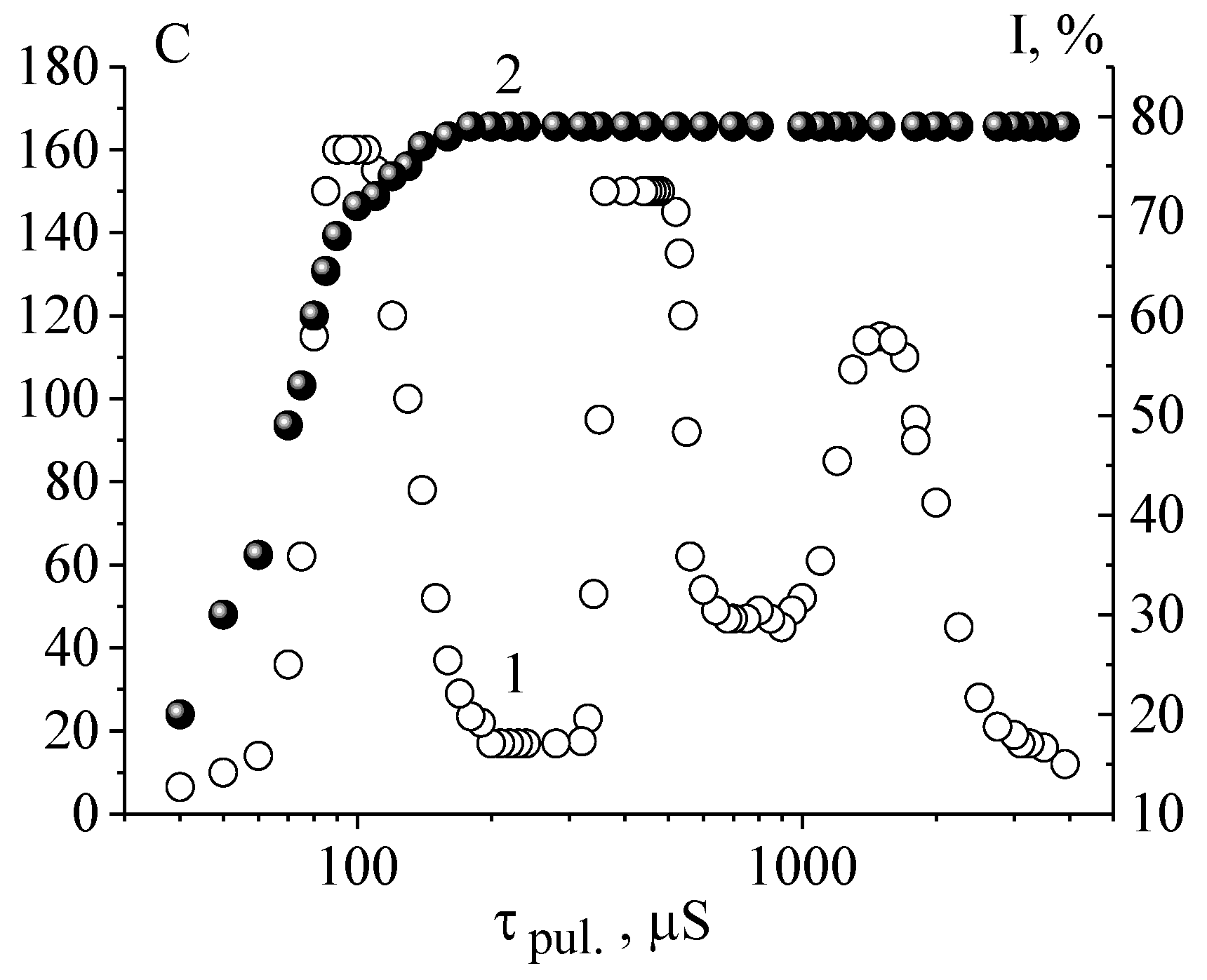
Depending on the time of the electric field action (duration of voltage pulses) and the cell thickness, there may occur several maxima of light scattering that may be treated as the scattering efficiency C (or contrast ratio) (
Figure 14). The emergence of the second and third maxima of light scattering efficiency occurs with increasing the cell thickness up to 16–20 μm [
16].
The maximum efficiency of light scattering and the maximum light transmittance without scattering are achieved at different durations of control voltage pulses. An increase in the pulse duration results in increasing the domain wall length and leads to irregular scattering structures. As a result, the density of scattering centers reduces; this is a reason for the light scattering efficiency decrease (
Figure 14).
After switching off the electric field, the transmitted optical radiation does not change in spectral composition, and there is no residual light scattering in the FLC layer (due to the absence of a helix). Since the magnitude of the spontaneous polarization does not exceed 50 nC/cm2, ferroelectric domains do not arise. Therefore, in the absence of an electric field, scattering and diffraction centers are absent. The saturation voltage is rather low and, consequently, the control voltage of an electro-optical cell is also quite small (less than 50 V).
The main possible applications of light-scattering FLC compositions are the following: polarizer-free visible and infrared optical shutters, energetically effective screens of electronic books, 3D visualizers (volumetric screens) of volumetric displays, etc. [
16,
27].
6.3. Spatially Inhomogeneous Modulation of Light Phase Delay
When the duration of voltage pulses supplied simultaneously to the electro-optical cell corresponds to different maxima of light scattering efficiency, the transitions between light-scattering modes (which correspond to light scattering maxima) result in the most chaotic changes in the position of a scattering indicatrix. As a result of a short-term switching on of light scattering (less than for 50 μs), structures with an almost random distribution of refractive index gradients are formed in the entire volume of the FLC. They cause a spatially inhomogeneous phase modulation of the light beam (over its cross section) passing through the electro-optical cell.
Spatially inhomogeneous modulation with a phase delay of the order of and more than π allows one to destroy the phase relations in a laser beam passing through the electro-optical cell and, further, to suppress the speckle noise in images formed due to the ability of laser rays to interfere.
This approach was used to develop the first electro-optical despeckler, the device that reduces the contrast of speckles and, due to this, suppresses the speckle noise in laser images. In [
28,
29], helix FLCs were used for this aim, and an alternating electric field was applied across the cell simultaneously at low and high frequencies, which caused spatial deformations of the helicoid in an FLC layer. Unfortunately, such a despeckler had serious drawbacks. First, the deformed helix structure of molecules changed the spectral composition of the laser radiation. Besides this, after the electric field was switched off, the residual scattering caused by the helices remained. Also, the light modulation frequency at the electric field strength of ~2 V/µm was limited by the value of 500 Hz, which hampers possible applications of this despeckler.
These drawbacks were eliminated after using new helix-free FLC in the experimental samples of a despeckler.
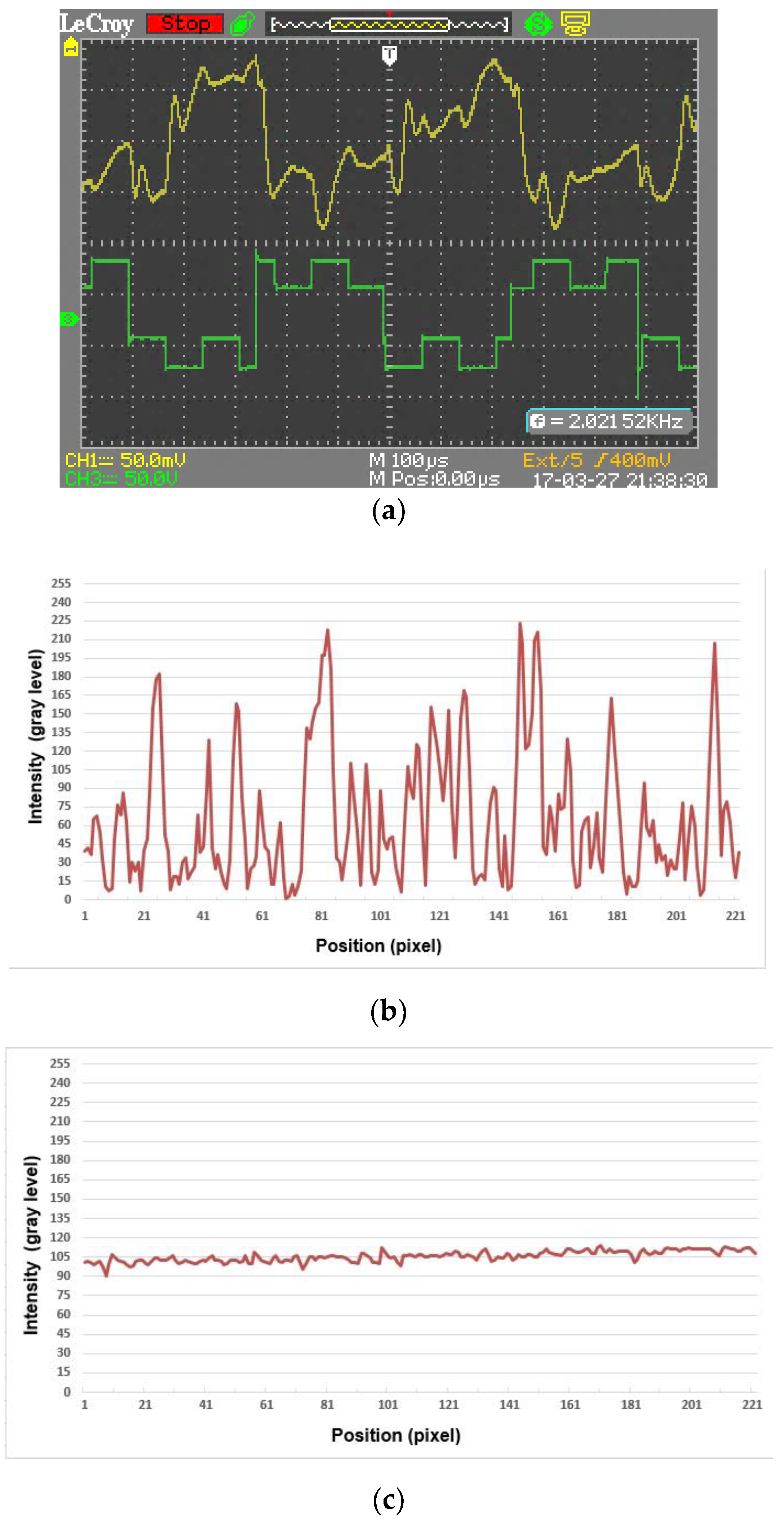
Figure 15 illustrates the operation of one of the best samples. Signals of the control voltage and the modulated optical response are shown in
Figure 15a. To create the different nonrepeating distributions of refractive index gradients in the volume of the FLC layer, two-frequency voltage pulses (meander) were supplied to the electro-optical cell, and pulses of low frequency (2 kHz) were modulated by pulses of high frequency (10 kHz).
In
Figure 15b,c, the speckle intensity distributions in the cross section of the laser beam behind the FLC electro-optical cell are presented for when the control voltage on the cell electrodes is not applied and is applied, respectively. The optical data were recorded using a CCD (charge-coupled device) camera and were processed using a special software product. The reduction in the contrast of the speckle pattern was calculated from the data in
Figure 15b,c as the ratio R between the contrast
C0 of a speckle pattern measured without the despeckler sample and the contrast
C1 of a speckle pattern measured with the despeckler sample: R = 10 log
10 (
C0/
C1) = 10 log
10 (0.82/0.07) = 10.2 dB [
30,
31].
The experiments confirmed the simplicity and high efficiency of the electro-optical despeckler prototype based on an electro-optical cell with the helix-free FLC. Such a device can be widely used in holography and in laser projection displays.
7. Conclusions
Based on our research results, we considered in detail the physical properties, light modulation characteristics, and possible applications of novel helix-free FLC developed and fabricated at the Lebedev Physical Institute, Moscow. They are distinguished by the spatially periodic deformation of smectic layers, a small value of spontaneous polarization, rather high viscosity, and the soliton mechanism of FLC director reorientation upon transition to the Maxwellian mechanism of energy dissipation.
For FLC with a viscosity in the range from 0.15 to 1.0 P, the frequency and field dependences of the electro-optical response time were studied under modulation of light transmission, light scattering, and light phase delay.
When modulating the light transmission in an electric field of the order of 1 V/μm (at the control voltage of ±1.5 V), the smallest response time (25 μs) and the largest modulation frequency interval (7 kHz, including 6 kHz for hysteretic-free modulation with continuous grayscale) were realized experimentally for the first time.
A theoretical model was proposed that described satisfactorily the deformation of smectic layers in the absence of the external electric field and the soliton mechanism of FLC director reorientation under an alternating electric field.
In certain compositions of the new FLC, intensive light scattering on transient domains was realized, including the discovery for the first time of bistable scattering with a memory time that can exceed the optical switching time (tens of microseconds) by 6 orders of magnitude (up to tens of seconds).
Initiated by the short-time switching on of light scattering, the spatially inhomogeneous phase light modulation due to random small-scale gradients of the FLC refractive index was studied. This modulation is capable of destroying the phase relations in a laser beam and of suppressing the speckle noise in images formed by the beam. Based on this, experimental samples of simple and effective electro-optical despecklers were studied for the first time.
Possible applications of the novel helix-free FLC are the fastest display devices (including displays using FLCoS, 3D, and FSC technologies), spatial light modulators, light-scattering polarizer-free modulators (including infrared devices and optical-state-memorizing ones), energetically effective screens of electronics books, 3D visualizers (volumetric screens) of volumetric displays, coding–decoding devices, etc.


