Article

Magnetic Field Effect on the Double Diffusive Natural Convection in Three-Dimensional Cavity Filled with Micropolar Nanofluid

1
Physics Department, College of Sciences Abha, King Khalid University, Abha 61421, Saudi Arabia
2
Research Unit of Metrology and Energy Systems, National Engineering School, Energy Engineering Department, Monastir University, Monastir City 5000, Tunisia
3
Mathematics Department, College of Science Abha, King Khalid University, Abha 61421, Saudi Arabia
4
Mechanical Engineering Department, College of Engineering Abha, King Khalid University, Abha 61421, Saudi Arabia
5
Energetic Laboratory of Thermal and Mass Transfers (LETTM), Faculty of Science Tunis, El Manar University, Tunis 2092, Tunisia
*
Author to whom correspondence should be addressed.
Appl. Sci. 2018, 8(12), 2342; https://doi.org/10.3390/app8122342
Submission received: 15 September 2018 / Revised: 11 November 2018 / Accepted: 15 November 2018 / Published: 22 November 2018
(This article belongs to the Special Issue Nanofluids and Their Applications)

Abstract

:
This article presents a three-dimensional numerical investigation of heat and mass transfers and fluid flow in a cavity filled with an Al2O3/water micropolar fluid under uniform magnetic field. To solve the governing non-dimensional equations, Finite Volume Method (FVM) based on 3-D vorticity-vector potential formulation has been employed. The effects of various parameters such as buoyancy ratio (−2 ≤ N ≤ 0), Rayleigh number (103 ≤ Ra ≤ 105), Hartmann number (0≤ Ha≤ 60), nanoparticles volume fraction (0 ≤ φ ≤ 0.06) and micropolar material parameter (0≤ K≤ 5) on flow structure and on heat and mass transfers are presented. The results illustrate that for the micropolar nanofluid model, both heat and mass transfer rates and three-dimensional character of the flow are smaller when compared with the pure nanofluid model. It is also observed that increase and decrease in heat and mass transfer rates is experienced due to increase in Rayleigh number and Hartmann number, respectively. It is also noted that increase in vortex viscosity parameter reduces the average heat and mass transfer rates and is more evident when the magnetic field is imposed. Combined effects of magnetic field and nanoparticles volume fraction on heat and mass transfers are also explored.

1. Introduction

In recent years, nanotechnology has attracted the research community through which an innovative technique is developed to enhance heat transfer by adding nanoparticles to pure fluid. The term ‘nanofluid’ was originally coined by Choi [1] to refer to the fluids with nanoparticle suspensions. The heat transfer characteristic of a nanofluid depends mainly on thermo-physical properties of the base fluid and the nanoparticles, along with nanoparticle’s shape, size and solid volume fraction [2,3,4]. It is clear that the addition of high thermal conductive nanoparticles to base fluid enhances thermal performance of the resultant mixtures. However, experimental investigations reveal that heat transfer is deteriorated with high nanoparticle volume fraction. Putra et al. [5] demonstrated experimentally that the Nusselt number reduces by enhancing a nanoparticle’s volume fraction for Al2O3/water and CuO/water. Wen and Ding [6,7] and Hwang et al. [8] confirmed similar results toPutra et al. [5]. On the other hand, the majority of computational studies reported an enhancement in heat transfer by adding nanoparticles. Khanafer et al. [9] critically analyzed the diverse models of nanofluids by measuring density, thermal expansion coefficients and viscosity. His findings establish that the heat transfer rate is amplified due to suspended nanoparticles. Jou and Tzeng [10] worked on Khanafer’s model and remarked that as the nanoparticle’s volume fraction increases, the average heat transfer coefficient enhances. Oztop and Abu-Nada [11] numerically investigated the natural convection in nanofluids by using FVM inpartially heated enclosures with different aspect ratios and established that the Nusselt numberwas augmented with an increase inthe nanoparticle’s volume fraction and Rayleigh number. Ho et al. [12] also observed the heat transfer rate enhancement with the addition of nanoparticles. Bouhalleb and Abbassi [13] carried out numerical investigation of natural convection in CuO–Water nanofluid within rectangular enclosures and ascertained that addition of CuO nanoparticles enhanced the heat transfer. Mahfoud and Bendjaghloli [14] used FVM to employ numerical investigation of natural convection in a truncated cone and found an heat transfer characteristics of cooling device by adding Cu–water nanofluid. In addition, the heat source length and inclined sidewalls’ angle influence the maximum temperature and the heat transfer rate.
Most researchers predicted an enhancement in heat transfer by the addition of nanoparticles. On the contrary, some researchers reported the deterioration in heat transfer. The mitigation or enhancement in heat transfer of nanofluid may be because of the hypothesis employed in the theoretical models used for their thermal properties. Hence, most of the numerical works assume that nanoparticles are in thermal equilibrium with the fluid and there is no slip between the nanoparticles and fluid molecules. Polidori et al. [15] given theoretical prediction for the experimental results of natural convection in an Al2O3–water nanofluid an external boundary layer and concluded that the models used for nanofluid viscosity and effective thermal conductivity model influenced the heat transfer rate. Ahuja [16] claimed from his experimental works that the augmentation in heat transfer may be due to the rotation of nanoparticles about their own axis due to the shear stress effect, and subsequently a three-dimensional hydrodynamic boundary layer was also observed.
The rotating micro-constituents’ effects in nanofluids should be considered to understand the fluid flow behavior in a better way and hence the micropolar theory explains the difference between experimental and numerical observations. This theory was originally proposed by Eringen [17] to elucidate fluid particles’ micro-motions which cannot be explained by the classical models. The aforementioned subject has been recently reviewed by Ariman et al. [18] and Lukaszewics [19]. The micropolar fluids have many engineering applications, such as the polymer fluids extrusion, animal bloods, exotic lubricants, colloidal and suspension solutions and liquid crystals solidification.
A few investigators have studied micropolar fluid natural convection in enclosures (Aydin and Pop [20], Zadravec et al. [21], Saleem et al. [22]). Jena et al. [23] has recently investigated transient micropolar double diffusive natural convection for buoyancy-opposing ratio and noticed that a monotonic decrease in the flow strength and heat and mass transfer ratesoccurs due to the vortex viscosity parameter. It should be noted that major researches in literature for the three-dimensional flow of micropolar fluids concerned numerical and/or analytical study of a flow due to stagnation point or stretching flat surface (Agarwal and et al. [24], Takhar and al. [25], Chamkha and et al. [26]).
With the wide use of a non-Newtonian fluids model with suspended particles in modern technology and industries, the extension to micropolar nanofluid model is desirable. In this context, Bourantas and Loukopoulos [27] introduced a micropolar nanofluid model to carry out theoretical investigation of natural convection in nanofluids and compared the nanofluidic suspensions with the micropolar theory. It is observed that the average Nusselt number increases with increase Rayleigh number when the microrotation number is kept constant. Hashemi et al. [28] investigated natural convection in Cu–water micropolar nanofluid with a heat-generated source in a porous medium. They found that as the material parameter increased, rotational strength of vortices and the particles micro-rotation increase and decrease, respectively. Hussanan et al. [29] explored the transient natural convection in micropolar nanofluid on a vertical plate using five types of oxide nanoparticles. They established that the temperature of nanofluid based on graphene oxide is much higher than the other nanofluids.
Magneto-convection research has been of extensive interest due to its vast engineering applications such as microelectronic mechanical devices, electronic packaging, and crystal growth in liquids [30]. Most of the researchers considered an electrically conducting fluid with low thermal conductivity which, in turn, restricts the heat-transfer enhancement in the cavity, and the use of nanofluid is a better option to improve the mechanism of heat transfer. Ghasemi et al. [31] considered the magnetic field impact on an Al2O3 water-nanofluid natural convection flow in square cavity and found that the heat transfer deteriorated with increased Hartmann number. Teamaha and El-Maghlany [32] investigated, numerically, nanofluid natural convection flow in a square enclosure in the presence of uniform generation and absorption of heat and magnetic field. They concluded that heat transfer is enhanced with solid nanoparticles’ volume fraction but decreased when the Hartmann number increased. Mahmoudi et al. [33] examined the natural convection in a two-dimensional triangular enclosure filled with nanofluid under the influence of magnetic field and noticed that the nanoparticles are more efficient once the Raleigh number is as high as 104. Mahmoudi and Abu-Nada [34] conducted numerical investigation of natural convection in CuO-water nanofluid to understand the impact of hydromagnetic heat transfer on. They analyzed the combined impact of both high magnetic field and nanofluids in heat transfer enhancement. Sheikholeslami et al. [35] studied the magnetic field impact on natural convection in Cu–water nanofluid and claimed that increase in nanoparticle volume fraction and Rayleigh number increases the average Nusselt number; however, it diminishes as the Hartmann number increases. Similar finding are reported by Zhou and Yan [36]. Abbassi et al. [37] carried out the lattice Boltzmann method based numerical investigation of natural convection in nanofluid with nanoparticle’s Brownian motion in open cavity under the influence of magnetic field. The authors found that heat transfer was reduced due to the addition of nanoparticles. Furthermore, the Brownian motion significantly affects the heat transfer rate according to the Rayleigh number, Hartmann number, and nanoparticle volume fraction. Al Kalbani et al. [38] experimented with different types of nanofluids with various shapes of nanoparticles and analyzed the oriented magnetic field effect on natural convection in an inclined square enclosure. They established that an increase in Rayleigh number and the nanoparticles’ volume fraction enhance the heat transfer, whereas the increase in Hartmann number reduced by the same. Javed et al. [39] carried out numerical investigation of flow of Cu-water nanofluid flow inside an isosceles triangular cavity under uniform magnetic field and illustrated that the flow strength enhanced as Rayleigh number increases and deteriorated as the Hartman number increases. Using the lattice Boltzmann method, Abbassi et al. [40] considered the nanofluid (water-Al2O3) flow in an incinerator-shaped enclosure with a heated source situated at the bottom. They found that the Rayleigh number, the nanoparticles volume fraction and the heat source height enhanced the heat transfer and influenced the flow and thermal structures. Bourantas and Loukopoulos [41] studied the effect of magnetic field on natural convection in micropolar nanofluid inside an inclined rectangular cavity and remarked that the thermal properties of the base fluid are altered by the presence of nanoparticles.
It is worth mentioning that very few papers have investigated the magnetic field effect on double diffusive convection in nanofluid. Akbar et al. [42] used Buongiorno mode and examined the effect of magnetic field on nanofluid double-diffusive natural convection on a linearly stretching sheet, and they identified that buoyancy ratio and magnetic field enhance the skin friction but decrease the heat and mass transfer rates.
On the basis of the aforementioned literature review, the authors’ understand that the three-dimensional double-diffusive natural convection in micropolar nanofluid filled cavity under the influence of uniform magnetic field has not been explored so far and hence is the topic of research of this article. The influences of relevant parameters such as Rayleigh number, Hartmann number, buoyancy ratio, nanoparticles’ volume fraction, and vortex viscosity parameter on flow structure and heat are elaborately analyzed.

2. Mathematical Formulation

Consider three-dimensional double diffusive convection inside a cubical enclosure filled with incompressible viscous electrically conducting micropolar nanofluid Al2O3/water as shown in Figure 1. The uniform magnetic field is applied perpendicularly to the differentially heated cavity walls. The fluid thermo-physical properties are supposed to be constant except the density in the buoyancy force term which is modeled by Boussinesq approximation. The base fluid (i.e., water) and nanoparticles are assumed to be in thermal equilibrium state. The thermo-physical properties of the nanofluid are listed in Table 1.
The viscous dissipation, radiation and Joules heating effects are judiciously neglected.
It is also assumed that the magnetic Reynolds number is as small as the induced magnetic field is neglected.
Using the dimensionless variables below: x = x L , y = y L , z = z L , t = α t L 2 ( U 1 , U 2 , U 3 ) = ( U 1 , U 2 , U 3 ) L α , T = T T c T h T c , C = C C l C h C l , and ( h 1 , h 2 , 0 ) = ( h 1 , h 2 , 0 ) L 2 α .
The microrotation vector h can be expressed as h = ( h 1 , h 2 , 0 ) ([24,25,26]).
The vorticity–vector potential formulation is employed in order to eliminate the pressure term which is delicate to treat. The ω and ψ are, respectively, defined by the following relations: ω = × U and U = × ψ .
Using the above hypothesis, the dimensionless governing equations [23,41,43] are:
2 ψ = ω
ω t + ( U · ) ω ( ω · ) U = Pr ( μ nf μ f + K ) ( ρ f ρ nf ) 2 ω Pr · K ( ρ f ρ nf ) 2 h + RaPr ( ( ρ β ) nf ( ρ β ) f ) ( ρ f ρ nf ) ( [ T z , 0 , T x ] N [ C z , 0 , C x ] ) + Pr   Ha 2 ( ρ f ρ nf ) ( σ nf σ f ) ( × ( J × e B ) )
T t + ( U · ) T = ( ( ρ C p ) f ( ρ C p ) nf ) ( k nf k f ) 2 T
C t + ( U · ) C = 1 L e ( ( ρ C p ) nf ( ρ C p ) f ) ( k f k nf ) 2 C
h t + ( U · ) h = Pr ( μ nf μ f + K 2 ) ( ρ f ρ nf ) 2 h + Pr · K ( ρ f ρ nf ) ( ω 2 · h )
J = Φ + U × e B
2 Φ = ( U × B ) = e B · ω
With: Pr = ν α , R a = g β T ( T h T c ) L 3 ν α , L e = α D , N = β C ( C h C l ) β T ( T h T c ) , H a = B 0 L σ ρ f υ f and K = k μ .
The effective density, the heat capacitance, the thermal expansion coefficient and the thermal diffusivity of nanofluid are given respectively by ([9,10,11]):
ρ n f = ( 1 ϕ ) ρ f + ϕ ρ p
( ρ C p ) n f = ( 1 ϕ ) ( ρ C p ) f + ϕ ( ρ C p ) p
( ρ β ) n f = ( 1 ϕ ) ( ρ β ) f + ϕ ( ρ β ) p
α n f = k n f ( ρ C p ) n f
The thermal conductivity and the effective dynamic viscosity of the nanofluid have been calculated experimentally ([44,45]) and is given as follows:
k n f = k f ( 1 + 7.47 ϕ )
μ n f = μ f ( 1 + 39.11 ϕ + 533.9 ϕ 2 )
The nanofluid electrical conductivity is given by ([33]):
σ n f = σ f [ 1 + 3 ϕ ( σ s σ f 1 ) ( σ s σ f + 2 ) ϕ ( σ s σ f 1 ) ]
Boundary conditions are given as follows:
Temperature and Concentration:
T ( 1 ,       y ,       z ) = 1 ,   C ( 1 ,       y ,       z ) = 1
T ( 0 ,       y ,       z ) = 0 , C ( 0 ,       y ,       z ) = 0
T z ) z = 0 = 0   and   C z ) z = 0 = 0
T z ) z = 1 = 0   and   C z ) z = 1 = 0
Vorticity:
At   x   =   0   and   x   =   1 :   ω 1 = 0 , ω 2 = U 3 x , ω 3 = U 2 x
At   y   =   0   and   y   =   1 : ω 1 = U 3 y , ω 2 = 0 , ω 3 = U 1 y
At   z   =   0   and   z   =   1 : ω 1 = U 2 z , ω 2 = U 1 z , ω 3 = 0
Vector potential:
At   x   =   0   and   x   =   1 : ψ 1 x = ψ 2 = ψ 3 = 0
At   y   =   0   and   y   =   1 : ψ 1 = ψ 2 y = ψ 3 = 0
At   z   =   0   and   z   =   1 : ψ 1 = ψ 2 = ψ 3 z = 0
Velocity, on all walls:
U 1 = U 2 = U 3 = 0
Calculations are performed for strong concentrated suspensions ([46]). These characterize the case in which the microelements near to the wall surface are unable to rotate. Thus, the micro-rotation vector boundary condition is defined as:
At   x = 0 , 1   ;   y =   0 , 1   and   z   =   0 , 1   :     h = 0
It is worth citing that the equations of vorticity (Equation (2)) and microrotation (Equation (5)) become uncoupled when K = 0, thus the flow is independent of the microrotation, and the governing equations depict the classical problem of Newtonian nanofluid natural convection in differentially heated enclosure.
The local Nusselt and Sherwood numbers are defined by:
N U = k n f T x k f T h T c L ) x = 0 , L = k n f k f T x ) x = 0 , 1
S h = D C x D C h C l L ) x = 0 , L = C x ) x = 0 , 1
The average Nusselt and Sherwood numbers, on the isothermal walls are defined as:
N ¯ u = 0 1 0 1 N u y z
and
S ¯ h = 0 1 0 1 S h y z

3. Numerical Approach and Benchmarking of the Code

The dimensionless governing equations are written in the scalar form as:
ω 1 = [ 2 ψ 1 x 2 + 2 ψ 1 y 2 + 2 ψ 1 z 2 ] , ω 2 = [ 2 ψ 2 x 2 + 2 ψ 2 y 2 + 2 ψ 2 z 2 ]   and   ω 3 = [ 2 ψ 3 x 2 + 2 ψ 3 y 2 + 2 ψ 3 z 2 ]
ω 1 t + x [ U 1 ω 1 Γ ω ω 1 x ] + y [ U 2 ω 1 Γ ω ω 1 y ] + z [ U 3 ω 1 Γ ω ω 1 z ] = ω 1 U 1 x + ω 2 U 1 y + ω 3 U 1 z   Pr · K ( ρ f ρ nf ) ( 2 h 1 x 2 + 2 h 1 y 2 + 2 h 1 z 2 ) + RaPr ( ( ρ β ) nf ( ρ β ) f ) ( ρ f ρ nf ) ( T z N C z ) + Pr   Ha 2 ( ρ f ρ nf ) ( σ nf σ f ) ( U 1 x )
ω 2 t + x [ U 1 ω 2 Γ ω ω 2 x ] + y [ U 2 ω 2 Γ ω ω 2 y ] + z [ U 3 ω 2 Γ ω ω 2 z ] = ω 1 U 2 x + ω 2 U 2 y + ω 3 U 2 z Pr · K ( ρ f ρ nf ) ( 2 h 2 x 2 + 2 h 2 y 2 + 2 h 2 z 2 ) + Pr   Ha 2 ( ρ f ρ nf ) ( σ nf σ f ) ( U 2 x )
ω 3 t + x [ U 1 ω 3 Γ ω ω 3 x ] + y [ U 2 ω 3 Γ ω ω 3 y ] + z [ U 3 ω 3 Γ ω ω 3 z ] = ω 1 U 3 x + ω 2 U 3 y + ω 3 U 3 z Pr · K ( ρ f ρ nf ) ( 2 h 1 x 2 + 2 h 1 y 2 + 2 h 1 z 2 ) + RaPr ( ( ρ β ) nf ( ρ β ) f ) ( ρ f ρ nf ) ( T x + N C x ) + Pr   Ha 2 ( ρ f ρ nf ) ( σ nf σ f ) ( U 3 x )
T t + x [ U 1 Γ T T x ] + y [ U 2 Γ T T y ] + z [ U 3 Γ T T z ] = 0
C t + x [ U 1 Γ C C x ] + y [ U 2 Γ C C y ] + z [ U 3 Γ C C z ] = 0
h 1 t + x [ U 1 Γ h h 1 x ] + y [ U 2 Γ h h 1 y ] + z [ U 3 Γ h h 1 z ] = Pr · K ( ρ f ρ nf ) ( ω 1 h 1 )
h 2 t + x [ U 1 Γ h h 2 x ] + y [ U 2 Γ h h 2 y ] + z [ U 3 Γ h h 2 z ] = Pr · K ( ρ f ρ nf ) ( ω 2 h 2 )
One notes that the above equations can be written in the following general form:
Φ t + x [ U 1 Φ Γ Φ Φ x ] + y [ U 2 Φ Γ Φ Φ y ] + z [ U 3 Φ Γ Φ Φ z ] = S Φ
With:
  • Φ : ω 1 ,   ω 2 ,   ω 3 ,   h 1 ,   h 2 ,   T   and   C
  • Γ Φ : dimensionless coefficient
  • S Φ : source term
Using the following expressions:
L 1 = U 1 Φ Γ Φ Φ x , L 2 = U 2 Φ Γ Φ Φ x   and   L 3 = U 3 Φ Γ Φ Φ x
The general equation can be written as:
Φ t + L 1 x + L 2 y + L 3 z = S Φ
The integration of the previous equation on a control volume leads to (Patankar [47]):
( Φ p Φ p 0 ) Δ x Δ y Δ z + ( L 1 e L 1 w ) Δ y Δ z Δ t + ( L 2 n L 2 s ) Δ x Δ z Δ t + ( L 3 f L 3 b ) Δ x Δ y Δ t = S ¯ Δ x Δ y Δ z Δ t
e, w, n, s, b and f represent the faces of control volume centered in P.
E, W, N, S, B and F refer to the node around the nodal point P.
The governing equations are developed as follows (Patankar [47])
Energy equation ( Φ = T ):
a p T p = a E T E + a w T w + a N T N + a S T S + a F T F + a B T B + b p
With b p = T p 0 Δ x Δ y Δ z Δ t
Concentration equation ( Φ = C ):
a p C p = a E C E + a w C w + a N C N + a S C S + a F C F + a B C B + b p
With b p = C p 0 Δ x Δ y Δ z Δ t
Vorticity equation: x-component ( Φ = ω 1 ):
a p ω 1 p = a E ω 1 E + a w ω 1 w + a N ω 1 N + a S ω 1 S + a F ω 1 F + a B ω 1 B + b p
With:
b p = ω 1 p 0 Δ x Δ y Δ z Δ t + ω 1 p ( U 1 E U 1 W 2 ) Δ y Δ z + ω 2 p ( U 1 S U 1 N 2 ) Δ x Δ z + ω 3 p ( U 1 F U 1 B 2 ) Δ x Δ y Pr · K ( ρ f ρ nf ) ( h 1 E + h 1 w Δ x ² + h 1 N + h 1 S Δ y ² + h 1 F + h 1 B Δ z ² ) Δ x Δ y Δ z + RaPr ( ( ρ β ) nf ( ρ β ) f ) ( ρ f ρ nf ) ( T F T B 2 N C F C B 2 ) p Δ x Δ y Pr   Ha 2 ( ρ f ρ nf ) ( σ nf σ f ) ( U 1 E U 1 W 2 ) Δ y Δ z
Vorticity equation: y-component ( Φ   = ω 2 ):
a p ω 2 p = a E ω 2 E + a w ω 2 w + a N ω 2 N + a S ω 2 S + a F ω 2 F + a B ω 2 B + b p
With:
b p = ω 2 p 0 Δ x Δ y Δ z Δ t + ω 1 p ( U 2 E U 2 W 2 ) Δ y Δ z + ω 2 p ( U 2 S U 2 N 2 ) Δ x Δ z + ω 3 p ( U 2 F U 2 B 2 ) Δ x Δ y Pr · K ( ρ f ρ nf ) ( h 2 E + h 2 w Δ x ² + h 2 N + h 2 S Δ y ² + h 2 f + h 2 B Δ z ² ) Δ x Δ y Δ z Pr   Ha 2 ( ρ f ρ nf ) ( σ nf σ f ) ( U 2 E U 2 W 2 ) Δ y Δ z
Vorticity equation: z-component ( Φ = ω 3 ):
a p ω 3 p = a E ω 3 E + a w ω 3 w + a N ω 3 N + a S ω 3 S + a F ω 3 F + a B ω 3 B + b p
b p = ω 1 p 0 Δ x Δ y Δ z Δ t + ω 1 p ( U 1 E U 1 W 2 ) Δ y Δ z + ω 2 p ( U 1 S U 1 N 2 ) Δ x Δ z + ω 3 p ( U 1 F U 1 B 2 ) Δ x Δ y Pr · K ( ρ f ρ nf ) ( h 1 E + h 1 w Δ x ² + h 1 N + h 1 S Δ y ² + h 1 F + h 1 B Δ z ² ) Δ x Δ y Δ z + RaPr ( ( ρ β ) nf ( ρ β ) f ) ( ρ f ρ nf ) ( T F T B 2 N C F C B 2 ) p Δ x Δ y Pr Ha 2 ( ρ f ρ nf ) ( σ nf σ f ) ( U 1 E U 1 W 2 ) Δ y Δ z
Microrotation equation: x-component ( Φ = h 1 ):
a p h 1 p = a E h 1 E + a w h 1 w + a N h 1 N + a S h 1 S + a F h 1 F + a B h 1 B + b p
With b p = h 1 p 0 Δ x Δ y Δ z Δ t + Pr · K ( ρ f ρ nf ) ( ω 1 p h 1 p )
Microrotation equation: y-component ( Φ = h 2 ):
a p h 2 p = a E h 2 E + a w h 2 w + a N h 2 N + a S h 2 S + a F h 2 F + a B h 2 B + b p
With b p = h 2 p 0 Δ x Δ y Δ z Δ t + Pr · K ( ρ f ρ nf ) ( ω 2 p h 2 p )
Vector potential equations:
ψ 1 p = 1 2 [ 1 Δ x ² + 1 Δ y ² + 1 Δ z ² ] 1 ( ω 1 p + + ψ 1 E + ψ 1 w Δ x ² + ψ 1 N + ψ 1 S Δ y ² + ψ 1 F + ψ 1 B Δ z ² )
ψ 2 p = 1 2 [ 1 Δ x ² + 1 Δ y ² + 1 Δ z ² ] 1 ( ω 2 p + + ψ 2 E + ψ 2 w Δ x ² + ψ 2 N + ψ 2 S Δ y ² + ψ 2 F + ψ 2 B Δ z ² )
ψ 3 p = 1 2 [ 1 Δ x ² + 1 Δ y ² + 1 Δ z ² ] 1 ( ω 3 p + + ψ 3 E + ψ 3 w Δ x ² + ψ 3 N + ψ 3 S Δ y ² + ψ 3 F + ψ 3 B Δ z ² )
The equations governing the problem are discretized by applying the control volume method. The power laws scheme is used to treat the convective terms. To discretize the temporal derivatives, the fully implicit procedure is retained to ensure the stability of computational scheme. The grids are considered uniform in all directions with additional nodes on boundaries. The successive relaxation-iterating scheme is employed in solving the resulting algebraic equations.
The solution is considered as acceptable as the next convergence criterion is satisfied for every time step:
i 1 , 2 , 3 max | ψ i n ψ i n 1 | max | ψ i n | + max | T n T n 1 | + max | C n C n 1 | 10 5
The superscript n corresponds to the iteration number. The solution is regarded as a steady state if the following criterion is satisfied:
max | ψ m ψ m 1 | max | ψ m | 10 5
where m denotes the number of the time step.
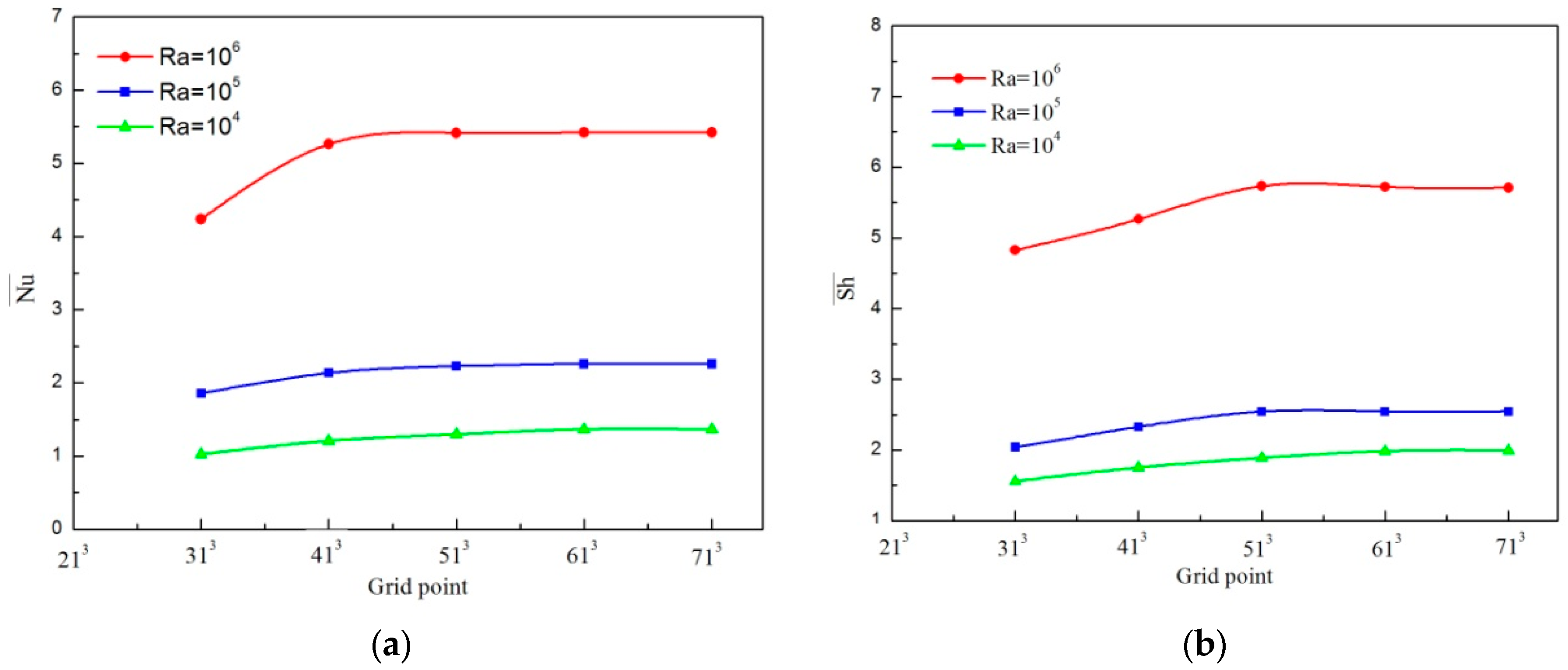
To determine an appropriate grid for numerical simulations, a grid independence study has been undertaken first. A dimensionless time step equal to 10−4 is retained. Figure 2 presents the effect of grid size on the average Nusselt and the average Sherwood numbers on the hot wall for N = −0.5, φ = 0.04 and K =1 for different Rayleigh numbers. Hence, the (51 × 51 × 51) grid was estimated to be convenient for the present work at least for Ra ≤ 105 because it allows a good compromise between the computational cost (a significant reduction of the execution time) and the accuracy of the results obtained.
To prove the precision of the present code, comparisons with previously published results are necessary. But due to the lack of availability of data on the particular problems of three-dimensional double diffusive convection in micropolar nanofluid investigated in this research, the validation of our three-dimensional code was made in different stages:
First, the 3-D double diffusive convection code for a Newtonian fluid is compared with the numerical results of Sezai and Mohamad [48]. The validation which is reported in a previous work (Abidi et al. [49]) shows good agreement.
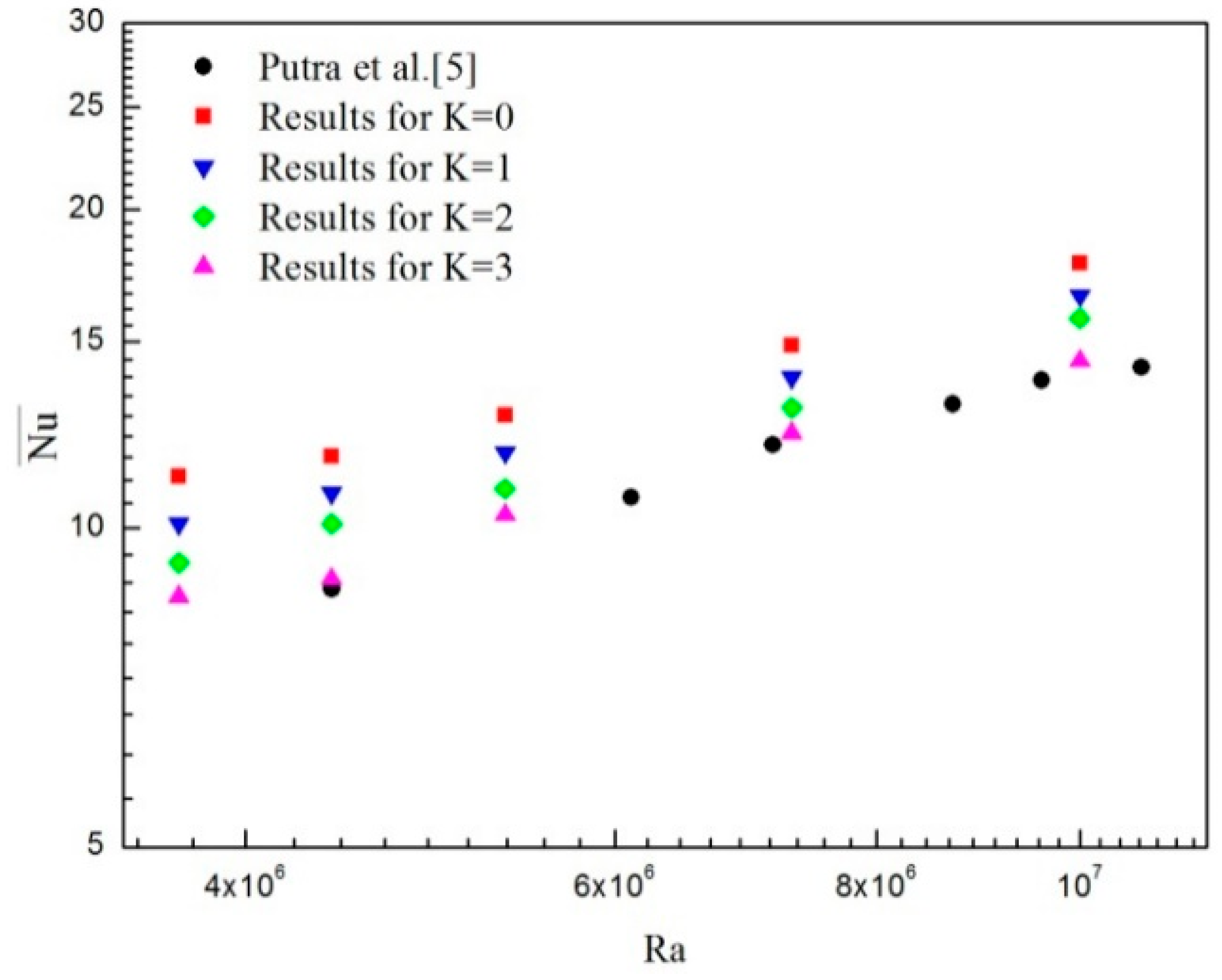
Second, the proposed three-dimensional nanofluid model that takes into account the nanoparticles microrotation is validated against experimental data of Putra et al. [5]. Figure 3 demonstrates that the experimental data and the present numerical results reveal similar trends. Apparently, as the microrotation parameter K augments our numerical results are closer to the experimental data. The proposed model is consistent with the assumptions describing that the nanoparticles microrotation must be taken into account.
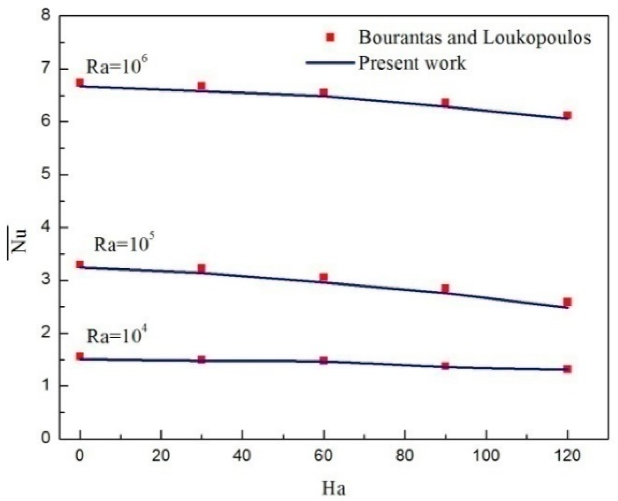
The third validation concerns the model of micropolar nanofluid under a magnetic field. To that end, a 2-D version of our code is derived and the results are verified against the numerical solutions reported by Bourantas and Loukopoulos [41]. As revealed in Figure 4, a very good agreement is found.
The results of the present investigation are in good agreement with the results of the models used [5,41,48]. Hence, the developed computer code can be effectively and reliably used to simulate the problem under consideration.

4. Results and Discussion

The numerical investigations are performed to explore the double-diffusive natural convection in a cubic cavity filled with Al2O3/water micropolar nanofluid with the influence of horizontal magnetic field.The present numerical simulation assume pure water as the base fluid with Pr = 6.2 and Le = 1.The computations are performed for the range of Rayleigh numbers (103 ≤ Ra ≤ 106), vortex viscosity parameter K (0 ≤ K ≤ 5) and buoyancy ratio N(−2 ≤ N ≤ 0), nanoparticle volume fractions of (0–6%)and Hartmann numbers (0–60). The influences of these parameters on flow dynamics and heat and mass transfers are detailed.

4.1. Comparison between the Micropolar Nanofluid and Nanofluid Models

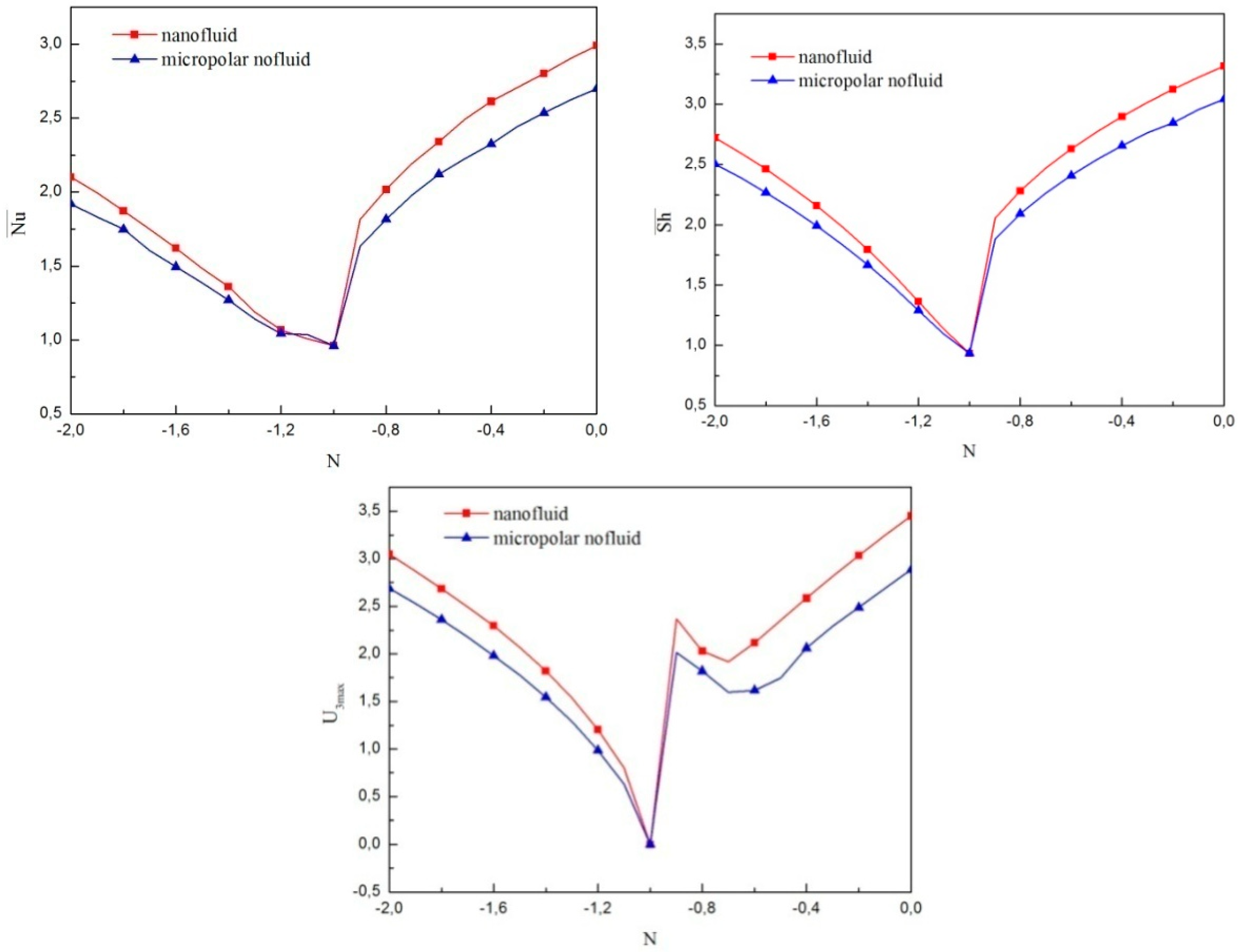
Comparison between micropolar and non-micropolar nanofluid models are made in terms of Nu ¯ , Sh ¯ and U3max as per the buoyancy ratio illustrated in Figure 5. It can be observed for a micropolar nanofluid model that all of Nu ¯ , Sh ¯ and U3max are smaller than that of a pure nanofluid model regardless the value of N considered. This gap is minimized adjacent to the transition value of N = −1 and the disparity is more significant for the thermal buoyancy-dominated zone.
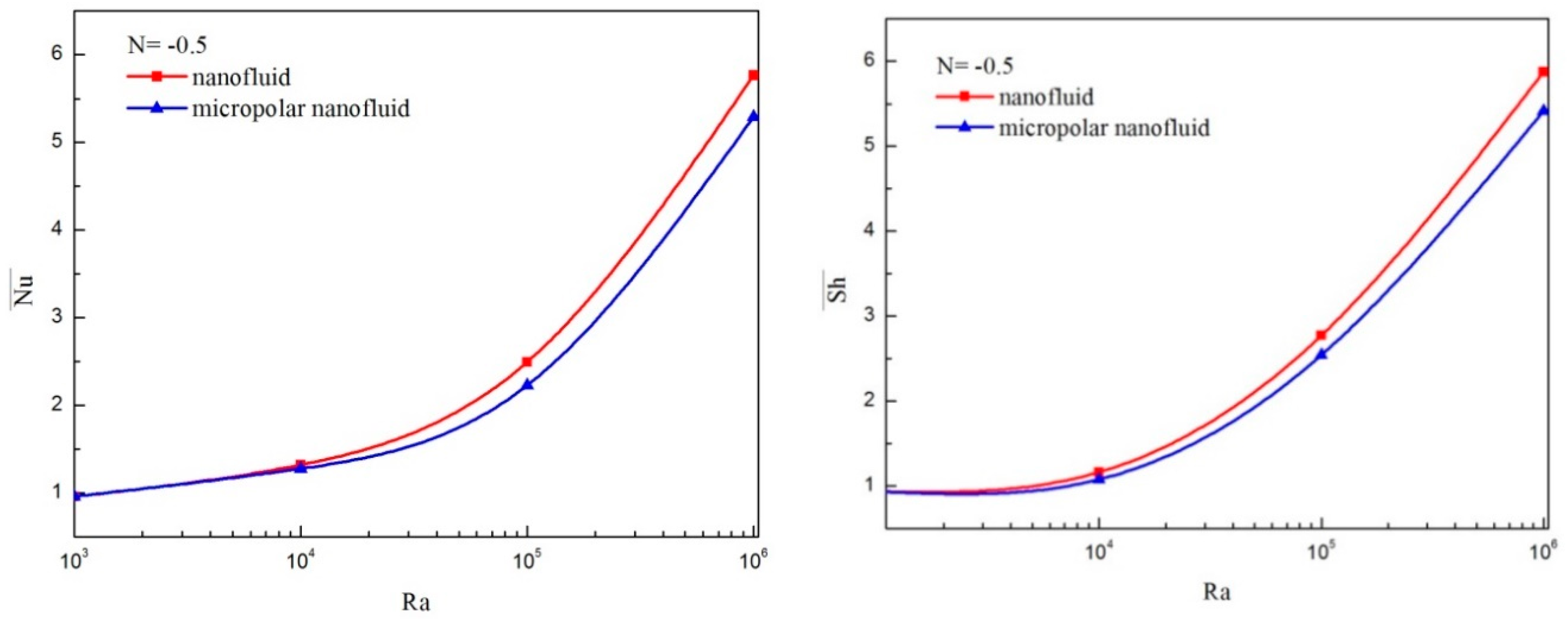
Variation of Nu ¯ and Sh ¯ against the Rayleigh is shown in Figure 6. Both micropolar and non-micropolar nanofluid models are considered with N = 0.5 in the thermal buoyancy-dominated regime and N = 2 in the solutal buoyancy-dominated regime. Both Nu ¯ and Sh ¯ are smaller than when considering the micropolar theory regardless of the value of Ra for both values of buoyancy ratio. However, the gap is more prominent when the Rayleigh numbers are enhanced. The current observations are in good agreement with the results of Bourantas and Loukopoulos [41] for two-dimensional flow by considering only the thermal gradient.
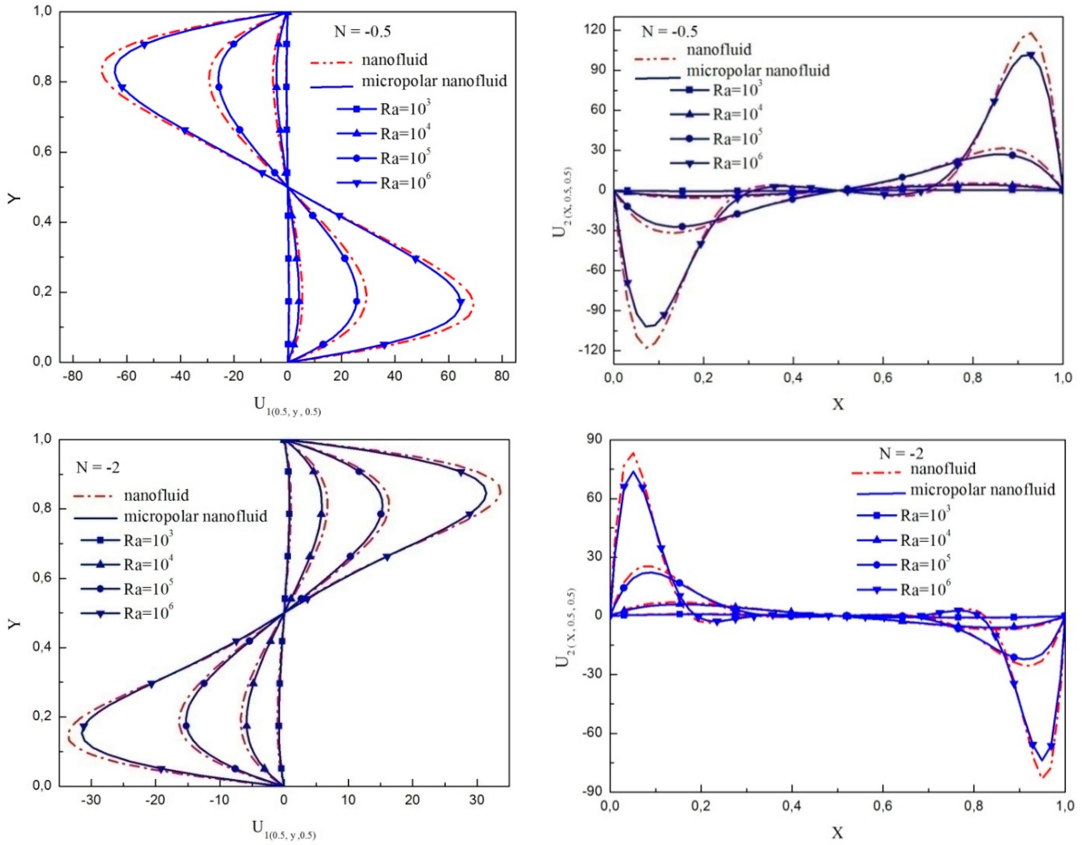
Figure 7 elucidates the variations of the horizontal and vertical velocity components at the Z = 0.5 plane according to the Rayleigh numbers for N = −0.5 and N = −2. Regardless of the modelconsidered, it is noticed that with increase in Rayleigh numbers, the flow regime is intensified and the magnitude of each component of velocity is increased. However, their magnitudes are higher in the case of ordinary nanofluid than in that of micropolar nanofluid. This difference becomes more significant for Ra up to 104 and implies that the insertion of the vortex viscosity parameter decelerates the principal flow strength for both regimes.
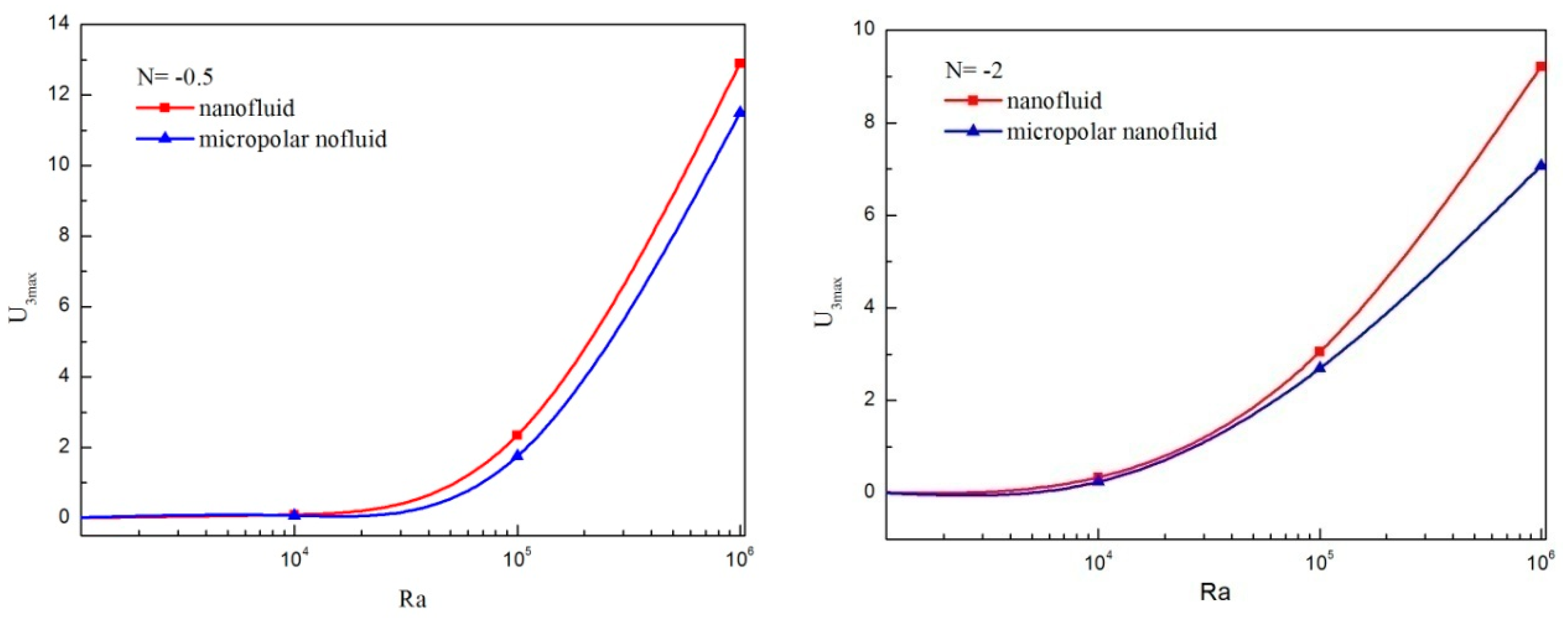
Figure 8 shows the maximum of the transverse velocity for various Rayleigh number applying the micropolar and non-micropolar nanofluid models in the absence microrotation for N = −0.5 and N = −2. For both cases, U3max is smaller without considering the micropolar theory and the gap is more noticeable when Ra outdoes 104. Hence, the consideration of micropolar material parameter weakens the three-dimensional character of the flow.

4.2. Effect of Magnetic Field

To study the impacts of uniform magnetic field, comparisons of isotherms, isoconcentrations, and projections of the flow lines in the mid (X–Y) plane are undertaken for thermally dominated (N = −0.5) and compositionally dominated (N = −2) regimes. The results for the average Nusselt and Sherwood numbers are also presented and analyzed.
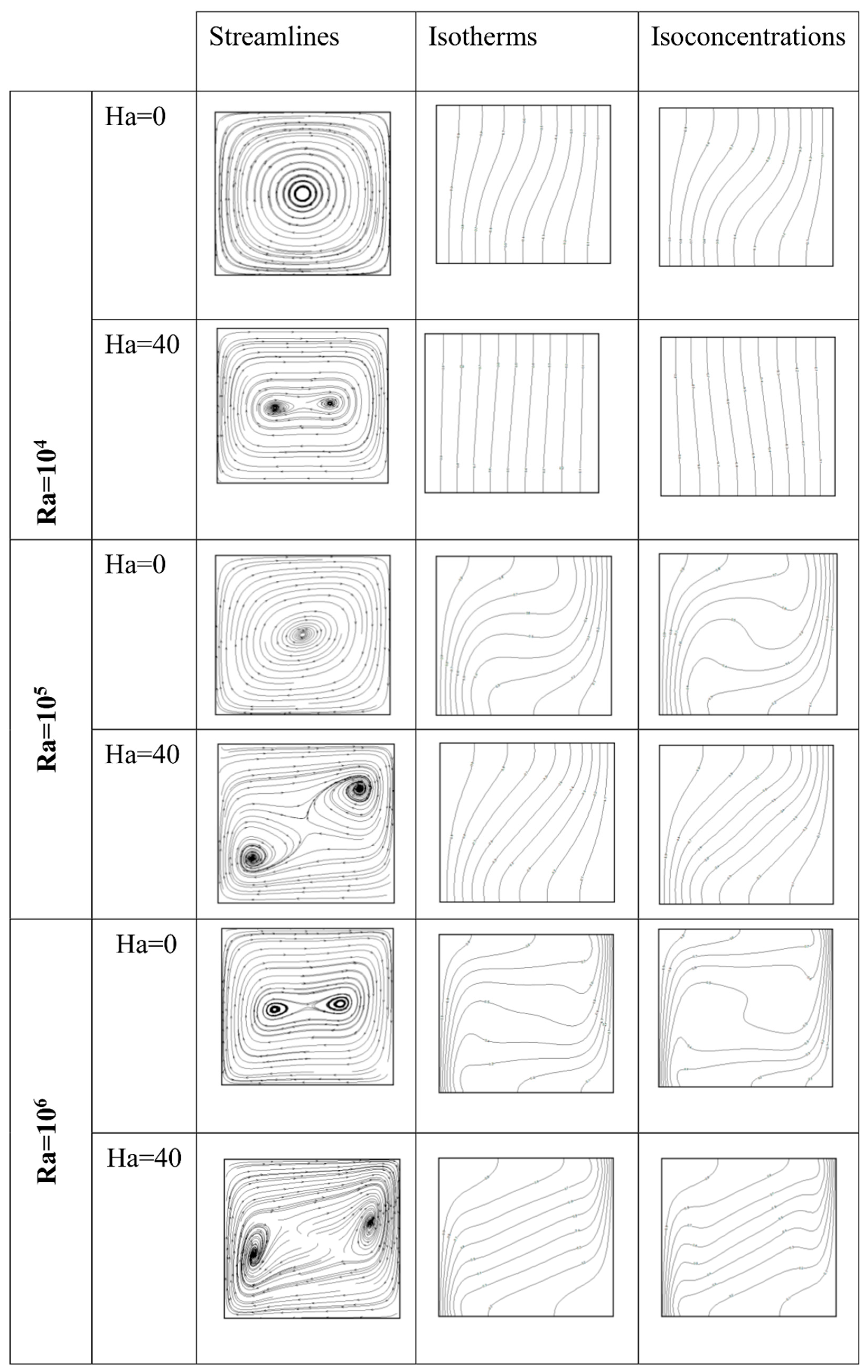
Figure 9 shows projections of flow lines, isotherms and isoconcentrations in the main plan Z = 0.5 for various combinations of Ra and Ha with φ = 4% for N = −0.5. In this case, the flow is mainly initiated by thermal volume forces so that the main flow direction is clockwise in the X–Y plane.
In absence of magnetic field (Ha=0), when the Rayleigh number enhances, the convection mechanism is more noticeable. The rotation cells become larger near the isothermal and the insulated walls indicating the strength of motion of the fluid. The projections of the flow lines on the mid X–Y plane are not closed but have a spiral form. Normally, the flow structure shows with two inner vortexes at high Rayleigh number (Ra= 105) but in the presence of magnetic field these two inner vortexes are initiated with lower Ra=104 and are moving towards the isothermal walls as the Rayleigh number increases.
When Ha = 0, an increase in Ra changes the direction of isotherms from almost vertical to the horizontal in the core and are stacked near the active walls. An isoconcentrations central zone is created and extended to the upper and lower regions of the enclosure as Ra increases. Once Ha = 40, both the thermal and solutal gradients diminish near the active walls. Furthermore, the temperature and concentration contours become inclined and parallel to each other within the core of the cavity as Ra increases and these changes in direction is an indication of weakness in convection flow due to the magnetic field.
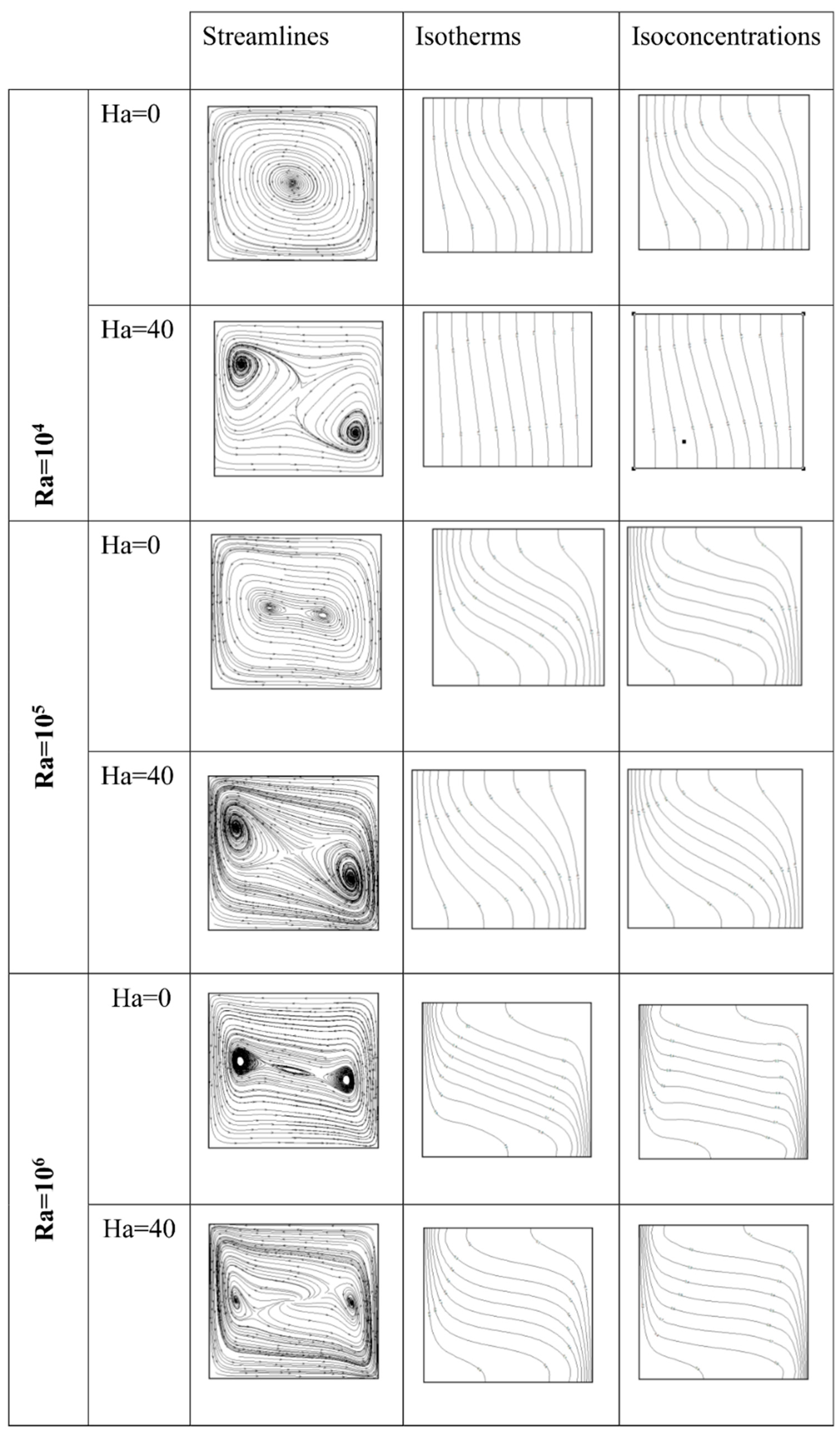
Figure 10 displays similar results as shown in Figure 9 except for N = −2. For this specific value of N, the main flow direction is reversed due to the enhancement in solutal effect. In the presence of magnetic field, the flow involves a counter-clockwise rotating main cell with two inner vortexes slightly titled to the hot wall and move towards the isothermal walls as the Rayleigh number increases.
When the influence of magnetic field is negligible (Ha = 0), both isotherms and isoconcentrations became inclined and parallel to each other within the cavity center with the increase in Rayleigh number. On the contrary, as the Rayleigh number remains constant both isotherms and isoconcentrations seem to be insensitive to the magnetic field.
To assess the magnetic field effect on the three-dimensional flow, the variation of the maximum of the transverse velocity versus the buoyancy ratio for two cases, Ha = 0 and Ha = 40 are illustrated in Figure 11. The presence of magnetic field causes an enhancement in the transverse velocity for both regimes regardless of the buoyancy ratio. However, its effect is more obvious for thermally-dominated zone than for the solutal-dominated one. The maximum of the transverse velocity has a minimum for N ≈ −1.
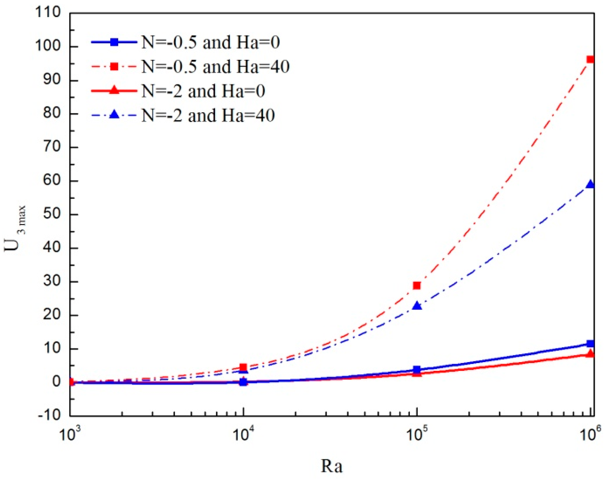
The variations of U3max according to the Rayleigh number without (Ha = 0) and with (Ha = 40) magnetic field for both thermally-dominated flow (N = −0.5) and solutal-dominated flow (N = −2) are presented in Figure 12. When the magnetic field is absent, U3max increases slightly with increase in Rayleigh number for both value of N. However, U3max enhanced considerably due to the influence of the magnetic field and is more prominent for the thermally dominated flow (N = −0.5).
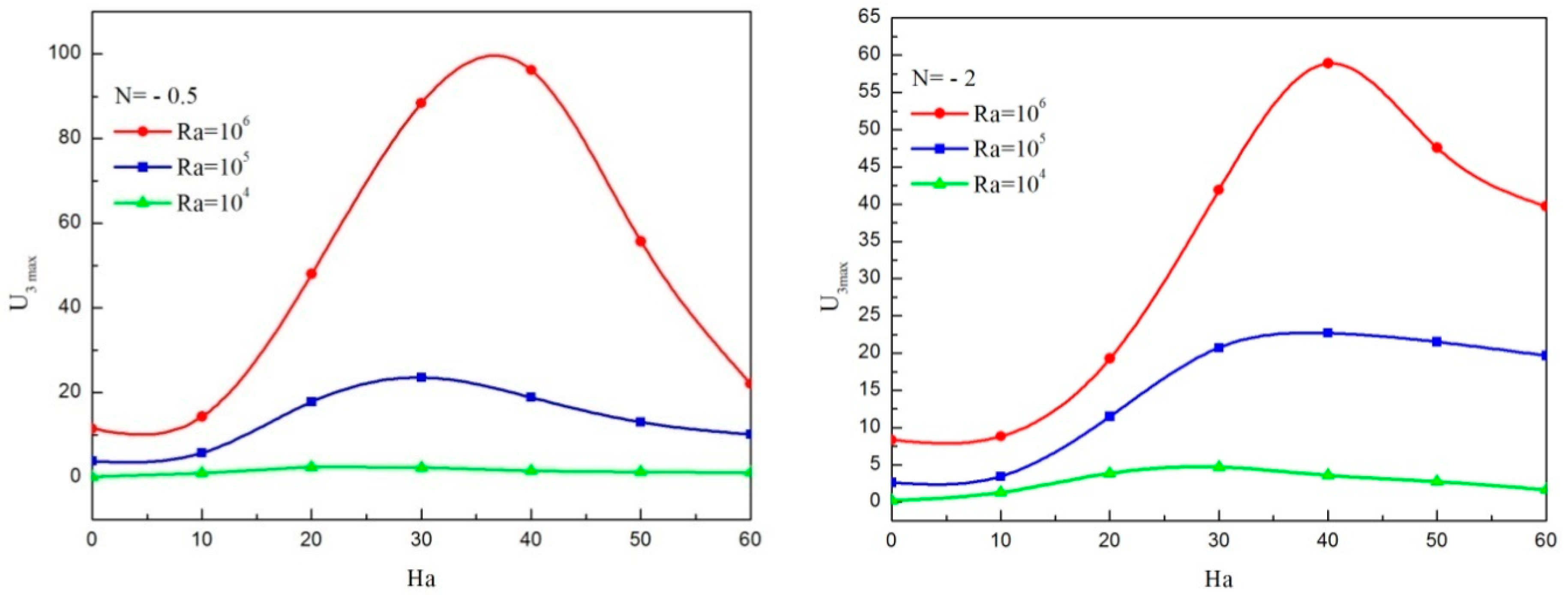
Figure 13 shows the effects of the Hartmann number on U3max with the Rayleigh number for both thermally-dominated flow (N = −0.5) and solutal-dominated flow (N = −2). As seen from the figure, the velocity is augmented for Hartmann numbers lower than the critical value of Ha and decreased by increasing the Hartmann number once more. Indeed, by increasing the Ha numbers, Lorentz force becomes stronger and overcomes the buoyancy force, which causes a considerable reduction in the three-dimensional character of the flow. The 3-D flow behavior against the Hartmann number is already discussed by Ozoe and Okada [43] and by Kolsi et al. [50] for three-dimensional natural convection of pure fluid. It is interesting to detect the existence of peak at which U3max is maximized regardless of the value of Ra. This peak value moves towards the highest value of Ha as an increase in Ra. In fact, for high Rayleigh number, convection is the dominant mechanism of heat transfer and the three-dimensional character of the flow is more prominent. Thus, to act against the convection mechanism, a stronger magnetic field must be applied and hence the Hartmann number should be higher. Therefore, the critical value of Ha is influenced by the values of Ra.
Also, the magnitude of U3max is greater for thermally-dominated flow (N = −0.5) than for solutal-dominated flow (N = −2). Besides, it should be mentioned that the minimum values of U3max occur when magnetic field is removed (Ha = 0) for both thermally-dominated flow (N = −0.5) and solutal-dominated flow (N = −2).
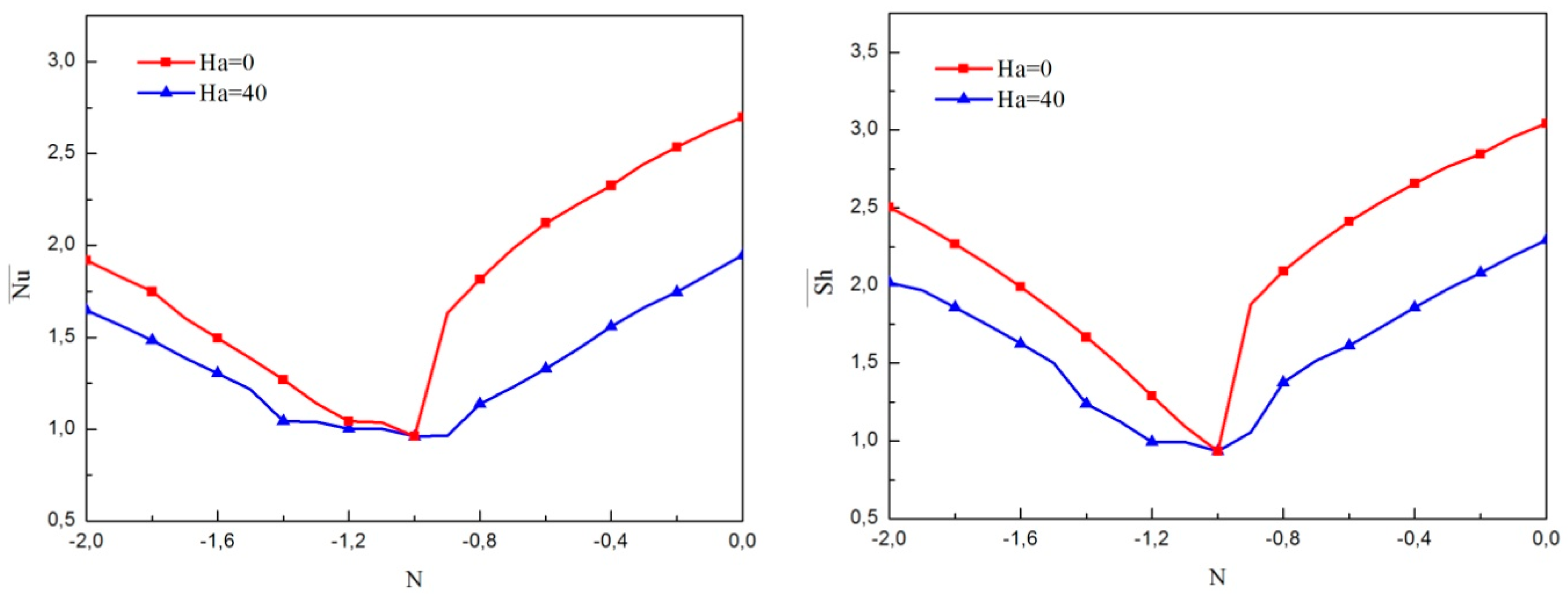
To highlight the effect of magnetic field on heat and mass transfers, the variations of Nu ¯ and Sh ¯ versus the buoyancy ratio for both cases, Ha = 0 and Ha = 40 are shown in Figure 14. It is clear that both Nu ¯ and Sh ¯ have a quasi-similar profile for both Ha = 0 and Ha = 40.
It is noticed that for both cases Nu ¯ and Sh ¯ have a decreasing trend upon increasing N in the negative sense. Beyond N = −1, Nu ¯ and Sh ¯ increase as N increases. The presence of a magnetic field decreased both Nu ¯ and Sh ¯ regardless of the buoyancy ratio. The magnetic field effect is more prominent for thermally-dominated regimes compared to solutal-dominated regimes.
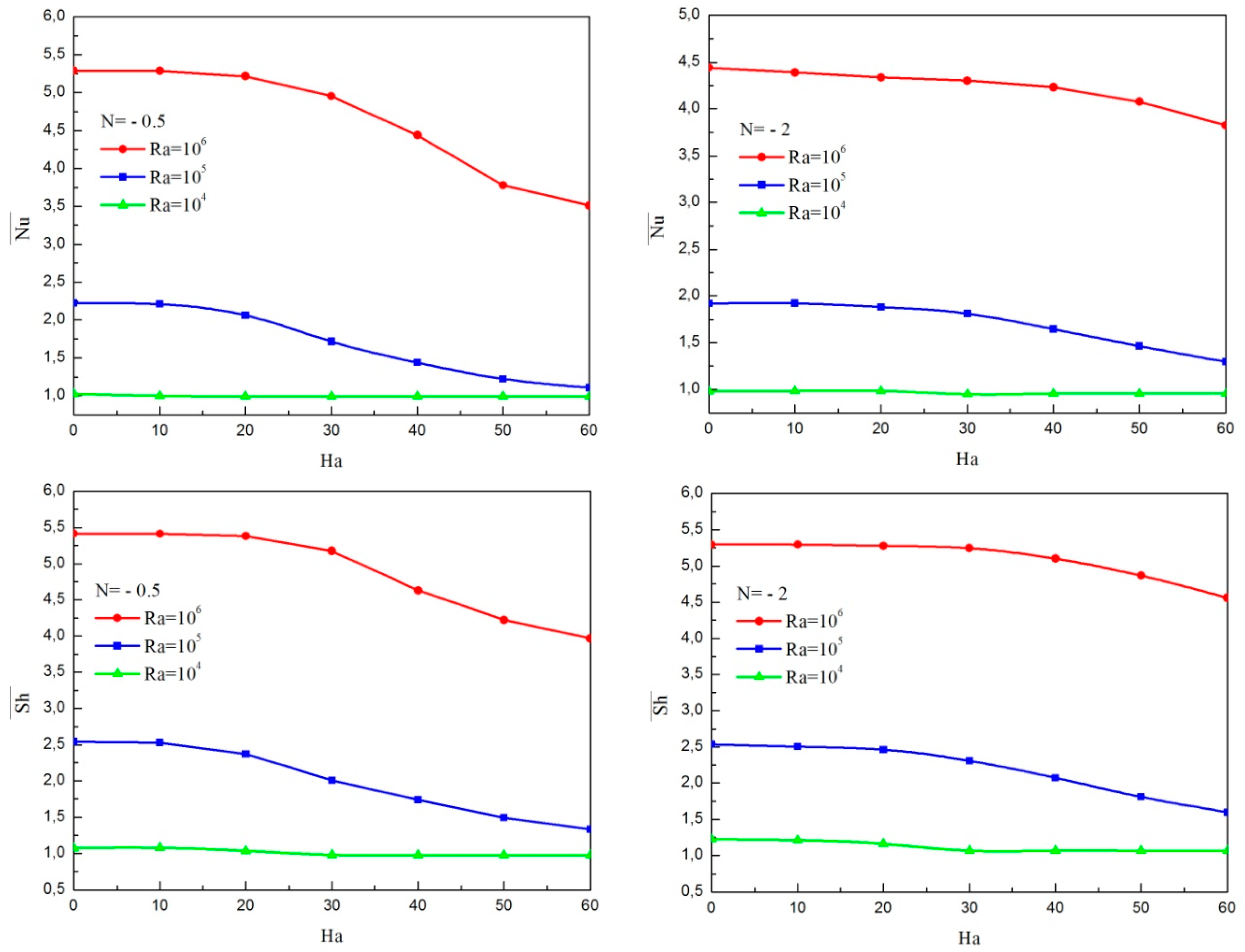
Figure 15 illustrates the variations of Nu ¯ and Sh ¯ with the Hartmann number for different Rayleigh numbers for both thermally-dominated regime (N = −0.5) and compositionally dominated regime. (N = −2). As revealed from the figure for both cases N = −0.5 and N = −2, increase in Ra number produces a heat and mass transfer enhancement. However, in contradiction, both Nu ¯ and Sh ¯ decrease with increase in the Hartmann number. Thus, the magnetic field suppress the heat and mass transfer within the cavity by reducing the average Nusselt and Sherwood numbers. Also, it can be noticed that the magnetic field effect is more significant for a high Ra number. Moreover, it should be mentioned that, the maximum values of Nu ¯ and Sh ¯ occur when the magnetic field is removed (Ha = 0) for both thermally dominated flow (N = −0.5) and solutal dominated flow (N = −2).
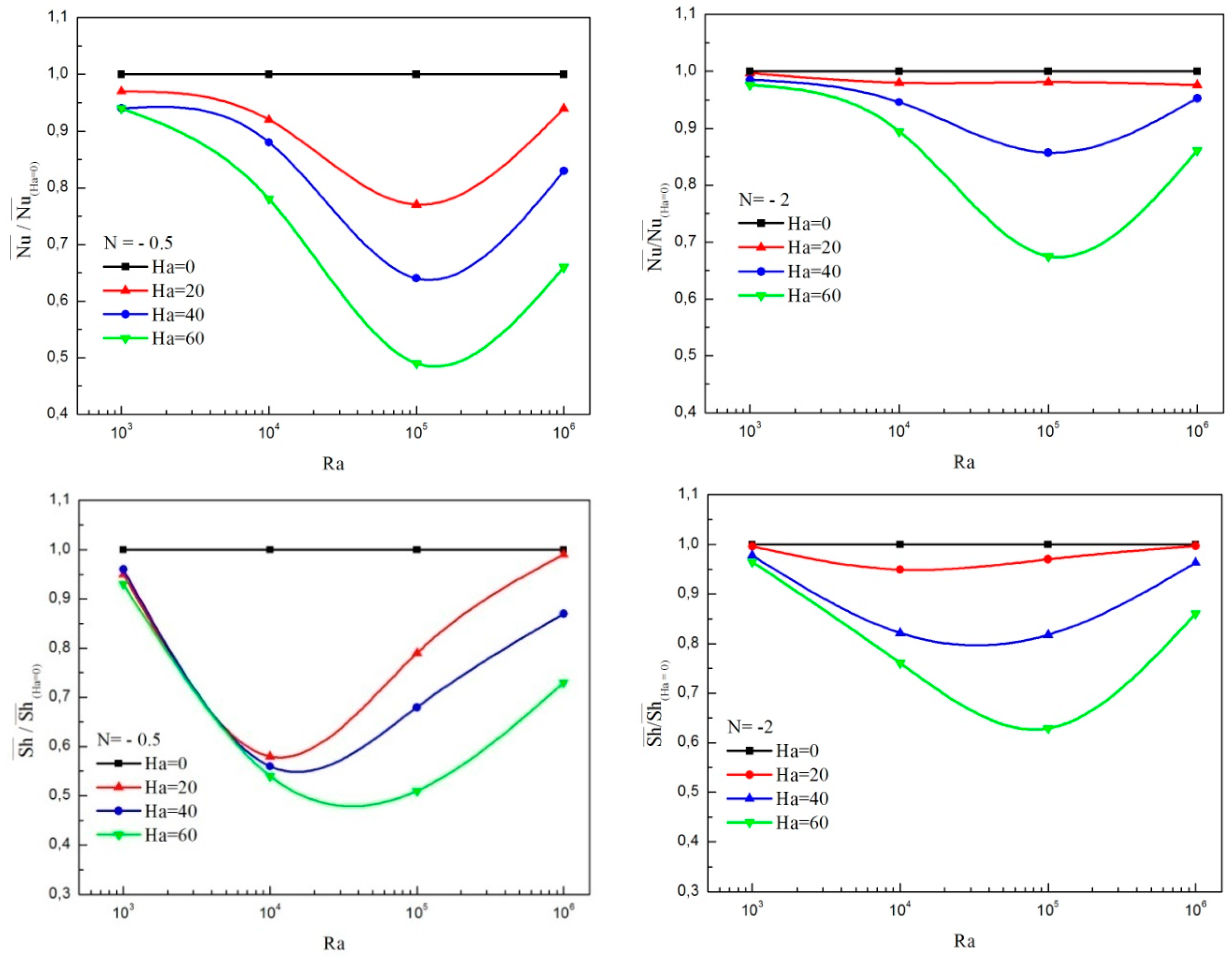
A closer examination of the average Nusselt and Sherwood ratios reveal the impacts of magnetic field on the cavity heat and mass transfer performances.
Figure 16 present respectively the variations of the average Nusselt number ratio Nu / ¯ Nu ¯ ( Ha = 0 ) and the average Sherwood ratio Sh / ¯ Sh ¯ ( Ha = 0 ) versus Rayleigh number at different values of the Hartmann number for both thermally-dominated regime (N = −0.5) and solutal-dominated one (N = −2). The average Nusselt and Sherwood number ratios at Ha = 0 are considered as reference values. The nanoparticles volume fraction is kept constant (φ = 0.04). The results show that a critical Rayleigh number minimizes both the average Nusselt number ratio and the average Sherwood number ratio regardless of the Hartmann number value. These minimums move towards higher Ra number as the Ha number increases.
Figure 17 presents the variations of Nu ¯ and Sh ¯ with nanoparticles volume fraction at Ra = 105 for various Hartmann numbers. As seen from the figure, for lower value of Ha, both Nu ¯ and Sh ¯ are decreased with increase in the nanoparticles volume fraction. In fact, adding nanoparticles to base fluid increase not only the thermal conductivity but also the viscosity of the fluid which results in the reduction of heat transfer rate. However, addition of nanoparticles enhances the heat and mass transfer for Ha more than 30.
Indeed, by increasing the Hartmann number, the rotation of the particles remains without intensive mixing in the fluid. At higher nanoparticles volume fraction, the effect of thermal conductivity exceeds the opposite effect of the viscosity. So, an increase in Hartmann number may lessen the deterioration in the heat transfer brought about by the effect of the viscosity. These results demonstrate the effectiveness of using magnetic field in enhancing the heat transfer by adding nanoparticles. In fact, one can control the magnetic field intensity and nanoparticles volume fraction to find an optimum heat transfer enhancement using nanoparticles.
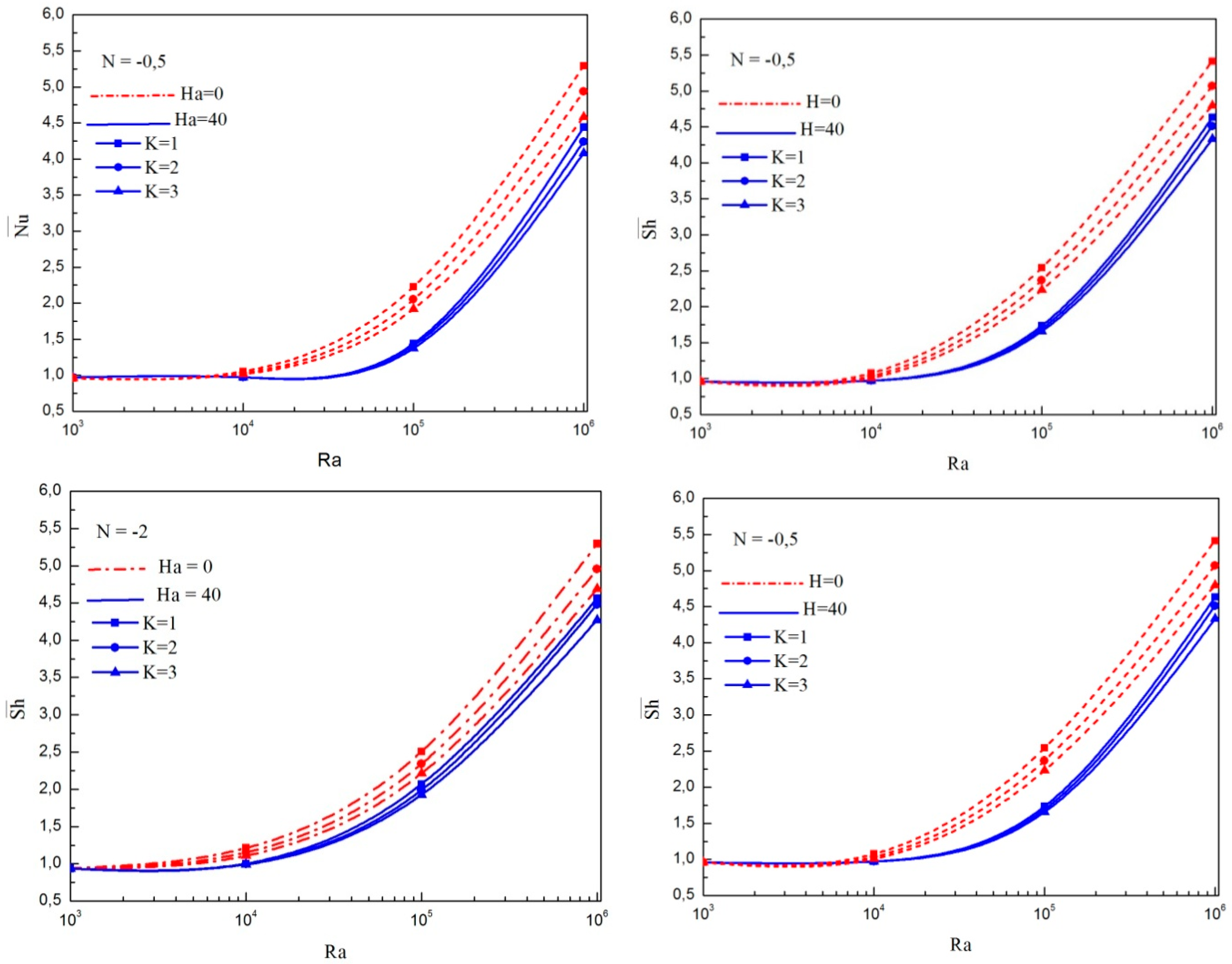
Figure 18a,b are plotted to explore the effect the Rayleigh number Ra for different vortex viscosity parameter K on the average Nusselt and Sherwood numbers without (Ha = 0) and with (Ha = 40) magnetic field. Irrespective of the Hartmann number, by keeping the vortex viscosity parameter K constant, Nu ¯ improves when increasing the Rayleigh number whereas the converse occurs when the Rayleigh number remains constant that is, the Nu ¯ reduces by increasing the vortex viscosity parameter. It can be observed also that there is a reduction in the heat transfer rate by enhancing the Ha number regardless of the vortex viscosity parameter value and this diminution became more significant for Ra up to 104. Furthermore, results for N = −2 shows similar tends for the impact of Rayleigh number and vortex viscosity parameter on Sh ¯ number. The vital difference is that the Sh ¯ number generally takes higher values than the Nu ¯ number.

5. Conclusions

A numerical investigation has been carried out to explore the magnetic field effects on 3-D double diffusive natural convection in a cavity filled with an Al2O3/water micropolar nanofluid. The principal conclusions are listed as follows:
-
For a micropolar nanofluid model, both heat and mass transfer rates are smaller than those of a pure nanofluid model.
-
Taking in to account particle microrotation, the three-dimensional flow character is weakened.
-
For a fixed value of nanoparticle volume fraction with a wide range Rayleigh number, the heat and mass transfer rates are reduced due to increase in the Hartman number.
-
For various Rayleigh numbers, the maximum of the transverse velocity enhances for Hartmann numbers lower than a critical value and diminishes as the Hartmann number increases. This critical value moves towards the highest value of the Ha number as increasing the Ra number.
-
In the absence of magnetic field, the increase in nanoparticles volume fraction deteriorates the heat and mass transfer. However, for Ha greater than 30, the enhancement of nanoparticle volume fraction increases the heat and mass transfer rates.
-
During non-existence of a magnetic field, an increase in vortex viscosity parameter diminishes the average heat and mass transfer rates and is more pronounced when the magnetic field is enforced. However, for Ha greater than 30, the enhancement of nanoparticle volume fraction increases heat and mass transfer rates.

Author Contributions

A.A. and Z.R. developed the problem and its FORTRAN code. A.A. and J.M. did the literature review, developed and implemented the computer code, and interpreted the subsequently obtained results. A.A. did the editing and removed the grammatical mistakes. A.A. in consultation of rest of the Authors reconfirmed the credibility of obtained solutions. All authors have read and approved the final manuscript.

Funding

This research received a funding from the Deanship of Scientific Research at King Khalid University of King Khaled Unversity (G.R.P-176-38).

Conflicts of Interest

The authors declare no conflict of interest.

Nomenclature

B0Magnetic field strength, N·m−1·A−1
CDimensionless species concentration, C = C C l C h C l
DSpecies diffusivity, m2/s
gAcceleration of gravity, m/s2
h Dimensionless microrotation vector
h The microrotation vector, m/s
HaHartmann number, dimensionless
KMicropolar vortex parameter
kVortex viscosity, kg. m−1·s−1
LEnclosure height, m
LeLewis number, L e = α / D
NBuoyancy ratio, N = β C ( C h C l ) β T ( T h T c )
N U ¯ Average Nusselt number
PrPrandtl number, Pr = ν / α
RaThermal Rayleigh number, R a = β T g ( T h T c ) L 3 / ( ν α )
S h ¯ Average Sherwood number
tDimensionless time, t = α t L 2
TDimensionless temperature, T = T T C T h T C
U Dimensionless velocity U = U L α
x, y, zDimensionless Cartesian coordinates, x = x’/L, y = y’/L, z = z’/L
Greek symbols
α Thermal diffusivity, m2s−1
βCCoefficient of compositional expansion, m3kg−1
βTCoefficient of thermal expansion, K−1
φSolid volume fraction
λThermal conductivity, Wm−1K−1
μDynamic viscosity of the fluid, kg m−1 s−1
υKinematic viscosity, m2s−1
ρDensity, kgm−3
σElectrical conductivity, Ω−1m−1
ω Dimensionless vorticity, ω = ω L 2 α
ψ Dimensionless vector potential of velocity, ψ = ψ α
Subscripts
ccold
ffluid
hhot
llow
nfAl2O3/water nanofluid
ssolid
Superscript
dimensional variables
1x-component
2y-component
3z-component

References

  1. Choi, U. Enhancing thermal conductivity of fluids with nanoparticles. In Developments and Applications of Non-Newtonian Flows, FED231; Siginer, D.A., Wang, H.P., Eds.; ASME: New York, NY, USA, 1995; pp. 99–105. [Google Scholar]
  2. Abu-Nada, E.; Ziyad, M.; Oztop, H.F.; Campo, A. Effect of nanofluid variable properties on natural convection in enclosures. Int. J. Therm. Sci. 2010, 49, 479–491. [Google Scholar] [CrossRef]
  3. Das, S.K.; Choi, S.U.S.; Patel, H.E. Heat Transfer in Nanofluids—A Review. Heat Transf. Eng. 2006, 27, 3–19. [Google Scholar] [CrossRef] [Green Version]
  4. Aybar, H.Ş.; Sharifpur, M.; Azizian, M.R.; Mehrabi, M.; Meyer, J.P. A Review of Thermal Conductivity Models for Nanofluids. Heat Transf. Eng. 2015, 36, 1085–1110. [Google Scholar] [CrossRef] [Green Version]
  5. Putra, N.; Roetzel, W.; Das, S.K. Natural convection of nano-fluids. Heat Mass Transf. 2003, 39, 775–784. [Google Scholar] [CrossRef]
  6. Wen, D.; Ding, Y. Natural convective heat transfer of suspensions of titanium dioxide nanoparticles (nanofluids). IEEE Trans. Nanotech. 2006, 5, 220–227. [Google Scholar]
  7. Wen, D.; Ding, Y. Formulation of nanofluids for natural convective heat transfer applications. Int. J. Heat Fluid Flow 2005, 26, 855–864. [Google Scholar] [CrossRef]
  8. Hwang, K.S.; Jang, S.P.; Choi, S.U.S. Flow and convective heat transfer characteristics of water-based Al2O3 nanofluids in fully developed laminar flow regime. Int. J. Heat Mass Transf. 2009, 52, 193–199. [Google Scholar] [CrossRef]
  9. Khanafer, K.; Vafai, K.; Lightstone, M. Buoyancy-driven heat transfer enhancement in a two-dimensional enclosure utilizing nanofluids. Int. J. Heat Mass Transf. 2003, 46, 3639–3653. [Google Scholar] [CrossRef]
  10. Jou, R.; Tzeng, S. Numerical research of nature convective heat transfer enhancement filled with nanofluids in rectangular enclosures. Int. Comm. J. Heat Mass Transf. 2006, 33, 727–736. [Google Scholar] [CrossRef]
  11. Oztop, H.F.; Abu-Nada, E. Numerical study of natural convection in partially heated rectangular enclosure filled with nanofluids. Int. J. Heat Fluid Flow 2008, 29, 1326–1336. [Google Scholar] [CrossRef]
  12. Ho, C.J.; Chen, M.W.; Li, Z.W. Numerical simulation of natural convection of nanofluid in a square enclosure: Effects due to uncertainties of viscosity and thermal conductivity. Int. J. Heat Mass Transf. 2008, 51, 4506–4516. [Google Scholar] [CrossRef]
  13. Bouhalleb, M.; Abbassi, H. Numerical Investigation of Heat Transfer by CuO–Water Nanofluid in Rectangular Enclosures. Heat Transf. Eng. 2016, 37, 13–23. [Google Scholar] [CrossRef]
  14. Mahfoud, B.; Bendjaghlouli, A. Natural Convection of a Nanofluid in a Conical Container. J. Ther. Eng. 2018, 4, 1713–1723. [Google Scholar] [CrossRef]
  15. Polidori, G.; Fohanno, S.; Nguyen, C.T. A note on heat transfer modeling of Newtonian nanofluids in laminar free convection. Int. J. Therm. Sci. 2007, 46, 739–774. [Google Scholar] [CrossRef]
  16. Ahuja, A.S. Augmentation of heat transport in laminar flow of polystyrene suspensions. I. Experiments and results. J. App. Phys. 1975, 46, 3408–3425. [Google Scholar] [CrossRef]
  17. Eringen, A.C. Theory of micropolar fluids. J. Math. Mech. 1966, 16, 1–18. [Google Scholar] [CrossRef]
  18. Ariman, T.; Turk, M.A.; Sylvester, N.D. Application of Micro continuum Fluid Mechanics. Int. J. Eng. Sci. 1974, 12, 273–293. [Google Scholar] [CrossRef]
  19. Łukaszewicz, G. Micropolar Fluids: Theory and Application; Birkhauser: Basel, Switzerland, 1999. [Google Scholar]
  20. Aydin, O.; Pop, I. Natural convection in a differentially heated enclosure filled with a micropolar fluids. Int. J. Therm. Sci. 2007, 46, 963–969. [Google Scholar] [CrossRef]
  21. Zadravec, M.; Hriberšek, M.; Škerget, L. Natural convection of micropolar fluidsin an enclosure with boundary element method. Eng. Anal. Bound. Elem. 2009, 33, 485–492. [Google Scholar] [CrossRef]
  22. Saleem, M.; Asghar, S.; Hossain, M.A. Natural convection flow of micropolar fluid in a rectangular cavity heated from below with cold sidewalls. Math. Comput. Model. 2011, 54, 508–518. [Google Scholar] [CrossRef]
  23. Jena, S.K.; Malla, L.K.; Mahapatra, S.K.; Chamkha, A.J. Transient buoyancy-opposed double diffusive convection of micropolar fluids in a square enclosure. Int. J. Heat Mass Transf. 2015, 81, 681–694. [Google Scholar] [CrossRef]
  24. Agrawal, R.S.; Bhargava, R.; Balaji, A.V.S. Finite element solution of non-steady three dimensional micropolar fluid flow at a stagnante point. Int. J. Eng. Sci. 1990, 28, 851–857. [Google Scholar] [CrossRef]
  25. Takhar, H.S.; Agarwal, R.S.; Bhargava, R.; Jain, S. Mixed convective non-steady 3-dimensional micropolar fluid flow at a stagnation point. Heat Mass Transf. 1998, 33, 443–448. [Google Scholar] [CrossRef]
  26. Chamkha, A.J.; Jaradat, M.; Pop, I. Three-dimensional micropolar flow due to a stretching flat surface. Int. J. Fluid Mech. Res. 2003, 30, 357–366. [Google Scholar] [CrossRef]
  27. Bourantas, G.C.; Loukopoulos, V.C. Modeling the natural convective flow of micropolarnano fluids. Int. J. Heat Mass Transf. 2014, 68, 35–41. [Google Scholar] [CrossRef]
  28. Hashemi, H.; Namazian, Z.; Mehryan, S.A.M. Cu-water micropolar nanofluid natural convection within a porous enclosure with heat generation. J. Mol. Liq. 2017, 236, 48–60. [Google Scholar] [CrossRef]
  29. Hussanan, A.; Salleh, Z.M.; Khan, I.; Sharidan, S. Convection heat transfer in micropolar nanofluids with oxide nanoparticles in water, kerosene and engine oil. J. Mol. Liq. 2017, 229, 482–488. [Google Scholar] [CrossRef]
  30. Sheikholeslami, M.; Roknib, H.B. Simulation of nanofluid heat transfer in presence of magnetic field: A review. J. Heat Mass Transf. 2017, 115, 1203–1233. [Google Scholar] [CrossRef]
  31. Ghasemi, B.; Aminossadati, S.M.; Raisi, A. Magnetic field effect on natural convection in a nanofluid field square enclosure. Int. J. Therm. Sci. 2011, 50, 1748–1756. [Google Scholar] [CrossRef]
  32. Teamah, M.A.; El-Maghlany, W.M. Augmentation of Natural Convective Heat Transfer in Square Cavity by Utilizing Nanofluids in the Presence of Magnetic Field and Uniform Heat generation absorption. Int. J. Therm. Sci. 2012, 58, 130–142. [Google Scholar] [CrossRef]
  33. Mahmoudi, A.H.; Pop, I.; Shahi, M. Effect of magnetic field on natural convection in a triangular enclosure filled with nanofluid. Int. J. Therm. Sci. 2012, 59, 126–140. [Google Scholar] [CrossRef]
  34. Mahmoudi, A.H.; Abu-Nada, E. Combined effect of magnetic field and nanofluid variable properties on heat transfer enhancement in natural convection. Numer. Heat Transf. Part A 2013, 63, 452–472. [Google Scholar] [CrossRef]
  35. Sheikholeslami, M.; Bandpy, M.G.; Ellahi, R.; Hassan, M.; Soleimani, S. Effects of MHD on Cu–water nanofluid flow and heat transfer by means of CVFEM. J. Magn. Magn. Mater. 2014, 349, 188–200. [Google Scholar] [CrossRef]
  36. Zhou, W.N.; Yan, Y.Y. numerical investigation of the effects of a magnetic field on nanofluid flow and heat transfer by the lattice boltzmann method. Numer. Heat Transf. Part A 2015, 68, 1–16. [Google Scholar] [CrossRef]
  37. Abbassi, M.A.; Mliki, B.; Djebali, R. Lattice Boltzmann Method for simulation of nanoparticle Brownian motion and magnetic field effects on free convection in a nanofluid-filled open cavity with heat generation/absorption and non uniform heating on the left solid vertical wall. Fluid Dyn. Mater. Proc. 2017, 13, 59–83. [Google Scholar]
  38. Al Kalbani, K.S.; Rahman, M.M.; Alam, M.S.; Al-Salti, N.; Eltayeb, I.A. Buoyancy Induced Heat Transfer Flow Inside a Tilted Square Enclosure Filled with Nanofluids in the Presence of Oriented Magnetic Field. Heat Transf. Eng. 2018, 39, 511–525. [Google Scholar] [CrossRef]
  39. Javed, T.; Mehmood, Z.; Siddiqui, M.A.; Pop, I. Effects of uniform magnetic field on the natural convection of Cu–water nanofluid in a triangular cavity. Int. J. Num. Meth. Heat Fluid Flow 2017, 27, 334–357. [Google Scholar] [CrossRef]
  40. Abbassi, M.A.; Safaei, M.R.; Djebali, R.; Guedri, K.; Zeghmati, B.; Alrashed, A.A.A. LBM simulation of free convection in a nanofluid filled incinerator containing a hot block. Int. J. Mech. Sci. 2018, 144, 172–185. [Google Scholar] [CrossRef]
  41. Bourantas, G.C.; Loukopoulos, V.C. MHD natural-convection flow in an inclined square enclosure filledwith a micropolar-nanofluid. Int. J. Heat Mass Transf. 2014, 79, 930–944. [Google Scholar] [CrossRef]
  42. Akbar, N.; Khan, Z.; Nadeem, S.; Khan, W. Double-diffusive natural convective boundary-layer flow of a nanofluid over a stretching sheet with magnetic field. Int. J. Num. Meth. Heat Fluid Flow 2016, 26, 108–121. [Google Scholar] [CrossRef]
  43. Ozoe, H.; Okada, K. Experimental heat transfer rates of natural convection of Molten Gallium supressed under an external magnetic field in either x, y or z direction. Int. J. Heat Mass Transf. 1992, 114, 107–114. [Google Scholar]
  44. Godson, L.; Raja, B.; Mohan, L.D.; Wongwises, S. Experimental investigation on the thermal conductivity and viscosity of silver-deionized water nanofluid. Exp. Heat Transf. 2010, 23, 317–332. [Google Scholar] [CrossRef]
  45. Pak, B.; Cho, Y. Hydrodynamic and heat transfer study of dispersed fluid with submicron metallic oxide particles. Exp. Heat Transf. 1998, 11, 151–170. [Google Scholar] [CrossRef]
  46. Guram, G.S.; Smith, C. Stagnation flows of micropolar fluids with strong and weak interactions. Comput. Math. Appl. 1980, 6, 213–233. [Google Scholar] [CrossRef]
  47. Patankar, S.V. Numerical Heat Transfer and Fluid Flow; McGraw Hill: New York, NY, USA, 1980. [Google Scholar]
  48. Sezai, I.; Mohamad, A.A. Double diffusive convection in a cubic enclosure with opposing temperature and concentration gradient. Phys. Fluids 2000, 12, 2210–2223. [Google Scholar] [CrossRef]
  49. Abidi, A.; Kolsi, L.; Borjini, M.N.; Ben Aissia, H. Effect of radiative heat transfer on three-dimensional double diffusive natural convection. Numer. Heat Transf. Part A 2011, 60, 785–809. [Google Scholar] [CrossRef]
  50. Kolsi, L.; Abidi, A.; Borjini, M.N.; Daous, N.; Ben Aïssia, H. Effect of an External Magnetic Field on the 3-D Un steady Natural convection in a cubical enclosure. Numer. Heat Transf. Part A 2007, 51, 1003–1021. [Google Scholar] [CrossRef]
Figure 1. Physical model with coordinate system.
Applsci 08 02342 g001
Figure 2. Grid independence study Nu ¯ (a) and Sh ¯ (b) with different Rayleigh numbers.
Applsci 08 02342 g002
Figure 3. Comparison of the average Nusselt number with experimental results of Putra et al. [5] versus Rayleigh number with increasing vortex viscosity parameter K for φ = 4%.
Applsci 08 02342 g003
Figure 4. Average Nusselt number comparison with Bourantas and Loukopoulos [41] for Ra = 105, Pr = 6.2, K = 2 and φ = 0.04.
Applsci 08 02342 g004
Figure 5. Variation of Nu ¯ , Sh ¯ and U3max with buoyancy ratio for both micropolar and non-micropolar nanofluid models for Ra = 105, φ = 0.04, Pr = 6.2 and Le = 1.
Applsci 08 02342 g005
Figure 6. Variation of Nu ¯ and Sh ¯ with Rayleigh number for micropolar and non-micropolar nanofluid models for N = −0.5 and N = −2.
Applsci 08 02342 g006aApplsci 08 02342 g006b
Figure 7. Variations of the horizontal and vertical velocity components at Z = 0.5 plan according to the Rayleigh number for both micropolar and non-micropolar nanofluid models for φ = 4%, for N = −0.5 (Top) and N = −2 (Bottom).
Applsci 08 02342 g007
Figure 8. Variations of U3max versus Rayleigh number for both micropolar and non-micropolar nanofluid models for N = −0.5 and N = −2.
Applsci 08 02342 g008
Figure 9. Projections of flow lines, isotherms and isoconcentrations in the main plane Z = 0.5 for various values Rayleigh number and Hartmann number with φ = 4%, K = 1, N = −0.5, Pr = 6.2 and Le = 1.
Applsci 08 02342 g009
Figure 10. Projections of flow lines, isotherms and isoconcentrations in the main plane Z = 0.5 for various values of Rayleigh number and Hartmann number with φ = 4%, K = 1, N = −2, Pr = 6.2 and Le = 1.
Applsci 08 02342 g010
Figure 11. Variation of U3max according to buoyancy ratio without (Ha = 0) and with magnetic field (Ha = 40) for Pr = 6.2, Le = 1, Ra = 105 and φ = 0.04.
Applsci 08 02342 g011
Figure 12. Variation of U3max according to the Rayleigh number in the plane X = 0.5 without (Ha = 0) and with magnetic field (Ha = 40) for φ = 4% and K = 1 for N = −0.5 and N = −2.
Applsci 08 02342 g012
Figure 13. Variations of U3max with Hartmann number for different Rayleigh number with φ = 4%, K = 1, N = −0.5 and N = −2.
Applsci 08 02342 g013
Figure 14. Variations of Nu ¯ and Sh ¯ according to buoyancy ratio without (Ha = 0) and with magnetic field (Ha = 40) for Pr = 6.2, Le = 1, Ra = 105 and φ = 0.04.
Applsci 08 02342 g014
Figure 15. Variations of both Nu ¯ and Sh ¯ according to Hartmann number for different Rayleigh numbers with φ = 4%, K = 1, N = −0.5 and N = −2 for Pr = 6.2 and Le = 1.
Applsci 08 02342 g015
Figure 16. Variations of the average Nusselt number ratio Nu / ¯ Nu ¯ ( Ha = 0 ) and the average Sherwood number ratio Sh / ¯ Sh ¯ ( Ha = 0 ) according to the Rayleigh number for different Hartman numbers with φ = 4%, K = 1, N = −0.5 and N = −2, Pr = 6.2 and Le = 1.
Applsci 08 02342 g016
Figure 17. Variations of Nu ¯ and Sh ¯ according to the nanoparticles volume fraction for different Hartmann numbers for Ra = 105, K = 1 and N = −0.5.
Applsci 08 02342 g017
Figure 18. Effect of Rayleigh number Ra and vortex viscosity parameter K on Nu ¯ and Sh ¯ without (Ha = 0) and with (Ha = 40) magnetic field for, N = −0.5 (Top) and N = −2 (Bottom).
Applsci 08 02342 g018
Table 1. Thermo-physical properties of pure water and Alumina (Al2O3) [2,3,4,5,6,7,8,9,10,11,12,13,14,15,16,17,18,19,20,21,22,23,24,25,26,27,28,29,30,31,32,33,34,35,36,37,38,39,40,41].
Pure Water Alumina (Al2O3)
Pr6.2
ρ (kg/m3)997.18933
Cp (J/kg·K)4179385
k (W/m.K)0.613401
β (K−1)21.10−51.67.10−5
σ (Ω·m)−10.051.10−10