Article

Implementation of Explosion Safety Regulations in Design of a Mobile Robot for Coal Mines

1
Department of Robotics, Faculty of Mechanical Engineering, VŠB-Technical University of Ostrava, 70833 Ostrava, Czech Republic
2
Instytut Podstaw Konstrukcji Maszyn, Konarskiego 18A, 44-100 Gliwice, Poland
3
Department of Systems Engineering and Automation, Universidad Carlos III de Madrid, 28911 Madrid, Spain
*
Authors to whom correspondence should be addressed.
Appl. Sci. 2018, 8(11), 2300; https://doi.org/10.3390/app8112300
Submission received: 18 October 2018 / Revised: 8 November 2018 / Accepted: 13 November 2018 / Published: 19 November 2018
(This article belongs to the Special Issue Advanced Mobile Robotics)

Abstract

:

Featured Application

The mobile robot described in the article is used for reconnaissance and inspection of underground coal mines after a catastrophic event. Knowledge from the article can be used as guidelines and aid for design of a mechatronic system with explosion safety for Group I (underground mines), Category M1 (presence of an explosive atmosphere).

Abstract

The article focuses on specific challenges of the design of a reconnaissance mobile robotic system aimed for inspection in underground coal mine areas after a catastrophic event. Systems that are designated for these conditions must meet specific standards and regulations. In this paper is discussed primarily the main conception of meeting explosion safety regulations of European Union 2014/34/EU (also called ATEX—from French “Appareils destinés à être utilisés en ATmosphères Explosives”) for Group I (equipment intended for use in underground mines) and Category M1 (equipment designed for operation in the presence of an explosive atmosphere). An example of a practical solution is described on main subsystems of the mobile robot TeleRescuer—a teleoperated robot with autonomy functions, a sensory subsystem with multiple cameras, three-dimensional (3D) mapping and sensors for measurement of gas concentration, airflow, relative humidity, and temperatures. Explosion safety is ensured according to the Technical Report CLC/TR 60079-33 “s” by two main independent protections—mechanical protection (flameproof enclosure) and electrical protection (automatic methane detector that disconnects power when methane breaches the enclosure and gets inside the robot body).

Graphical Abstract

1. Introduction

Despite the constant improvement of mining technology and ever more comprehensive knowledge of the geological composition of coal resources, there are still catastrophes that happen to underground coal mines. Thousands of miners die from mining accidents each year, especially from underground coal mining [1,2]. Underground coal mining is considered to be much more hazardous than hard rock mining due to flat-lying rock strata, the presence of methane gas, and coal dust.
The focus of the project “System of the mobile robot TeleRescuer for inspecting coal mine areas affected by catastrophic events” (supported by European Commission research fund Coal and Steel) was the development and realization of a system for virtual teleportation (virtual immersion) of rescuers to the underground areas of a coal mine that have been closed due to a catastrophic event within them [3]. It was an international project managed by a consortium composed of the Silesian University of Technology (Gliwice, Poland), the VSB—Technical University of Ostrava (Ostrava, Czech Republic), the Universidad Carlos III de Madrid (Madrid, Spain), COPEX (Katowice, Poland), Simmersion GmbH (Groß-Siegharts, Austria), and Skytech Research (Gliwice, Poland) during years 2014–2017. All authors of this article are members of the consortium team.
The inspection with use of a mobile robot should take place primarily in situations and places where the presence of a rescue team is absolutely precluded (e.g., after a decision to withdraw the team). In some situations, the robot could for a long time (e.g., a few or dozen days) remain in the danger zone as a remote measurement observatory. It seems to be recommended that the robot could be remotely controlled from a safe room (rescue base). It should be equipped with a set of cameras and a set of sensors for the analysis and recording of physical parameters of the mine and composition of the mine atmosphere. One should also consider the possibility of using a robot vehicle as a means of transport to provide e.g., a specialized equipment to/from the rescue base to/from the rescue team present in the danger zone (going to the zone or returning) or to the crew waiting for help.
A mobile robot that is designed for harsh conditions must be able to properly operate in such conditions [4]. This includes not only a heavy-duty construction and good driving abilities, but primarily the robot must not make the situation even worse by, for example, causing a methane explosion. To secure this, most countries adopted certain regulations and standards for all devices that are intended for areas with potential risk of explosion, and these regulations must be indispensably followed.
This article describes a practical application of said regulations for the mobile robot TeleRescuer. After the initial overview of the related legislation in the main world regions and analysis of existing mobile robots for similar tasks, TeleRescuer is introduced by a brief description of individual subsystems. Then follows the main part of the article—implementation of explosion safety regulations that begins by selecting the overall concept of protection, which is then described in detail (separation of electrical components into galvanic isolated subsystems; flameproof enclosure with an example of the performed stress analyses; automatic safety gas detector; and, other protections).

2. State of Art

2.1. Legislation Overview

When designing the robot in the underground coal mine environment, it is necessary to take into account the requirements for safety in potentially explosive atmospheres, based on the standards in force in the country of use.
In the European Union, the legislation is based on the European Commission Directive 2014/34/EU (also called ATEX), which sets requirements for manufacturers and operators of equipment that is designed to work in potentially explosive atmospheres [5]. The requirements in this document result from national standards adopted by individual countries. In the EU, these national standards are harmonized with the IEC 60079 Series Explosive Atmosphere Standards [6].
In China, the GB standard—Guobiao system is applied (Chinese national standards issued by the Standardization Administration of China), together with standards GB3836, which are identical to IEC 60079 [7].
In the United States of America, this issue is addressed by the legislation of Hazardous Locations (abbreviated to HazLoc), which aims to control the risks that are related to the explosion in certain environments [8].
In the Russian Federation and several neighbouring countries, the document “Technical Regulations CU TR 012/2011 on the safety of equipment in explosion hazardous environments” [9] is in use.
In Australia, this is solved by the NSW Coal Mine Health and Safety Regulation [10]. In Brazil, the INMETRO Regulation “Portaria 83:2006” states the requirements for electrical equipment for use in explosive atmospheres of vapours and gases [11].
It should be mentioned that all of the above-mentioned documents approach the problem more or less equally—they classify environments into several levels of risk and for each level offer specific ways to achieve the required safety.

2.2. Existing Mobile Robots

There are a number of projects related to problems of mobile robots in underground coal mines [12,13,14]. One of the most important differences between these robots when compared to the “normal” field mobile robots should be the ability to work in the potentially dangerous environment of coal mines by fulfilling the corresponding directives.
An example of a mobile robot that is designed for usage in coal mines is the Mine Rescue Robot (MINBOT) [15]. Its second generation—MINBOT-II—is developed based on the experiences learnt from the applications and experiments of the first generation (MINBOT-I) shown in Figure 1. The robot is controlled remotely by the operator via optical fibre. Unlike the previous version, MINBOT-II has its own power supply. The most interesting information—compliance with explosion safety regulations—is not mentioned.
The mobile robot Numbat (CSIRO—Division of Exploration and Mining, Kenmore, Australia) shown in Figure 1 is a mine reconnaissance robot designed in the 1990s by the Australian Commonwealth Scientific and Industrial Research Organization. The Numbat is an eight-wheeled mobile platform with an onboard gas analysis package to provide information on the environmental conditions within the mine [16].
Another example of a mobile robot for underground mines is Wolverine, as developed by Remotec (Oak Ridge, TN, USA)—Figure 2. Originally a military robot, which used to serve as a traditional bomb squad robot, has been made mine permissible [17]. It weighs over 550 kg and it is driven by explosion-proof motors and rubber tracks. It is equipped with navigation and surveillance cameras, lighting, atmospheric detectors, night vision capability, two-way voice communication, and a manipulator arm. The robot is operated remotely from a safe location and has the capability of exploring up to 1.5 km, communicating vital information about the conditions in the mine over a fibre optic cable. The operator can see real-time information, including video and concentrations of combustible and toxic gasses.
The Gemini-Scout (Sandia National Laboratories, Albuquerque, NM, USA)—Figure 2 is fully equipped with cameras and sensors, enabling it to provide feedback on environmental and structural conditions and can serve as a two-way communications device with trapped miners, providing critical life-saving information. The weight of the robot is about 90 kg. Explosion safety is solved as explosion-proof housing (thus the robot cannot work when methane is present—it has only the M2 category implemented.) [18].
A similar conception of the chassis and the method of explosion safety as Gemini-Scout robot is used on the MPI robot by Emag-Piap consortium (Warsaw, Poland)—Figure 3. The robot is aimed at support for the teams of mine rescuers [19]. The robot is supposed to be certified for Group 1, category M1 (protection by explosion-proof housing plus protection of overpressure), but this combination is arguable. It weighs about 1100 kg, maximal velocity 0.7 m/s, distance range 1 km, length 240 cm, width 115 cm, height 180 cm, supply 42 VDC. It is not possible to move the robot through the 80 cm diameter hole in dams.
The mobile robots for coal mines described above have some weaknesses like their large size (cannot go through the fire-dam tube), teleoperation only (no autonomy), no ability to create a three-dimensional (3D) map of the surroundings and—most probably—problems with meeting the actual explosion safety directive requirements. Other serious problems include: communication distance is shorter than required, ability to overcome obstacles is low, and autonomous movement ability is weak or non-existent. Some tracked robots are not suitable for crossing rough surfaces that are caused by an explosion in a coal mine.
The goal of the TeleRescuer project was to deal with all of these problems and design a mobile robot that would be fully applicable and useful in the mentioned situations.

2.3. Requirements for the Robot

Required functionality and parameters of the robot TeleRescuer were specified based on the analysis of existing robots and a survey made in the Central Mine Rescue Station (Bytom, Poland).
The proposed unmanned vehicle should have a compact structure, small size, and high stability and mobility. Its dimensions cannot exclude the possibility of transport through a fire-dam tube (Ø 800 mm) in an anti-explosion dam. The device should also have as low weight as possible in order to enable manual handling (additional transport handles would be useful). Uncomplicated control shall be performed remotely—from the rescue base. Instrumentation (sensors, cameras) should be protected from possible damage.
The main obstacles and hindrances which the robot can encounter during the inspection and which should be dealt with include:
  • significant reduction or total lack of visibility,
  • high temperature (up to 60 degrees Celsius) and humidity (up to 100%),
  • difficult terrain, i.e., significant excavation slope, uneven ground, water spills of different depths,
  • reduced cross-sectional area of mining working,
  • numerous obstacles specific to cave-ins and related to stored improperly or scattered material, and
  • technological obstacles: structures of conveyors, conveyor drives, excavation protection structures and their intersections, hydraulic or wood racks, railroad tracks, turnouts, loading ramps, winches, transformers, switchgear or single switches, pumps, hoses, drainage, sheet, elements of concrete, machine constructions and their fixing—beam, struts, chains, wire ropes, tubes, pipes, cables, ventilation fans, and lutes.
As far as the sensory system is concerned, the device should be able to measure temperature, relative humidity and the four major gases (O2, methane—CH4, CO, CO2). Beneficial could also be the ability to measure the air velocity and temperature of selected elements of the robot body. The exact scope and frequency of measurement should always be programmed after consultation with the head of the rescue operation. There also must be equipment for recording and transferring images to the operator (colour cameras operating in the visible light spectrum supported with additional lighting and infrared cameras), together with a 3D mapping functionality (not critical).
The respondents considered that the optimum working time for the robot would be:
  • about 3–4 h of work, and
  • from several hours to several days in idle mode.

3. Description of the Mobile Robot Telerescuer

The TeleRescuer robot (Figure 4) consists of the main chassis with four independent tracked arms (eight motors, gears, motor controllers, batteries, and the main control system are placed in a flameproof housing), a sensory arm with a sensory head, a 3D laser scanner unit, and a mote deploying subsystem (motes are small Wi-Fi repeater modules) [20,21]. Every subsystem has its own independent power supply.

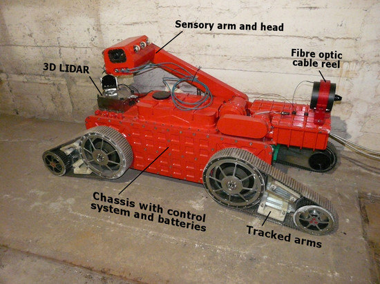
3.1. Main Robot Chassis and Control System

The main robot chassis contains the motion subsystem, the main control system (MCS), the communication subsystem and power supply. The motion subsystem is based on four identical independent flipper arms with tracks; each of the arms contains two brushless DC motors.
The MCS is responsible for motion control, management of communication between all subsystems, autonomous behaviour, 3D map building, collision prevention, etc. This requires high computational power while keeping low power consumption, it was thus decided to use the IPC (Industrial PC) architecture [22,23].
The control system software is based on the Robotic Operating System (ROS). The system is modularly divided into several parts (ROS nodes) that are responsible for individual logical tasks (motion, sensors, autonomy, communication, 3D map building, etc.). The software architecture and implementation does not affect explosion safety, thus it is not described in detail here. More information can be found in [22].

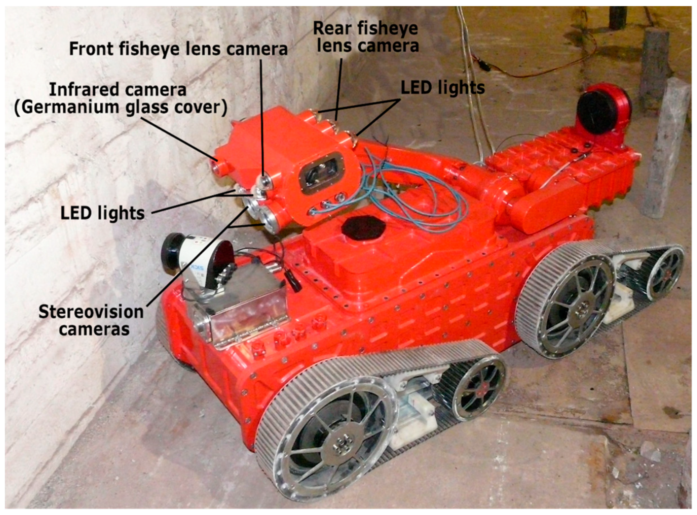
3.2. Sensors, 3D Mapping and Autonomy

A very important part of the mobile robot is the sensory head located on the top of the tiltable sensory arm (see Figure 5). The sensory head contains five cameras (two for stereoscopic view, one with a wide field of view, one for rear view and one thermal camera), LED lighting, various gas sensors, and an inertial measurement unit. Elevation and rotation of the sensory head and lifting of the additional methane arm (this arm is part of the main sensory arm) are realized by only one DC motor with four electromagnetic clutches for selection of the type of movement. Detail description is beyond the scope of this paper.
The mapping subsystem is intended for 3D map building during robot movement in a coal mine [24]. This system contains a Sick LMS111 two-dimensional (2D) laser scanner mounted on a rotating axis adding the third dimension to scanning. Using a special visualization part of the operator control system [25,26,27], the rescuers can inspect the mine and plan their intervention. Mapping can also be used for regular inspections of coal mine areas—the system compares the actual map with the previous one and can report unexpected changes in the tunnel shape (a part of the tunnel is starting to collapse, etc.).
The second use of this subsystem is to provide real-time information about robot surroundings for the autonomy control. Autonomy is used for the automatic return of the robot in the case of losing communication with operator. An example of autonomous navigation control can be found in [28].

3.3. Operator—Robot Communication

A reliable system has been designed for communication between the operator and the robot. The main communication channel is based on an optical fibre cable. In case the cable is broken, a backup wireless communication system is activated automatically. The wireless network is built during robot motion by units called motes that act as repeaters to achieve hundreds of meters wirelessly. The motes are located on the rear part of the robot and they are automatically dropped depending on the intensity of the wireless signal.

3.4. Technical Data

The most important technical data of the mobile robot TeleRescuer include:
  • weight: 590 kg,
  • width: 741 mm,
  • length: 2100 mm (tracks horizontally), 1540 mm (tracks vertically),
  • height: 500 mm (minimal height, tracks horizontally), 920 mm (standing on tracks), additional +780 mm with arm in the top-most position,
  • ability to drive through a tube with inner diameter 800 mm,
  • driving speed: 0.5 m/s (software limited),
  • battery capacity: approx. 2 h of operation,
  • communication cable length: 2000 m, and
  • pulling force: 1200 N (measured during tests).

4. Implementation of IEC 60079 for TeleRescuer

The robotic system TeleRescuer is intended for use in European countries, so the design was made according to the European Commission Directive 2014/34/EU [5] and the IEC 60079 Series Explosive Atmosphere Standards.

4.1. Classification

IEC 60079 classifies devices into two groups:
  • Group I—equipment intended for use in underground mines and parts of surface installations of such mines, liable to be endangered by the explosion of methane and/or coal dust. Group I is further divided into Categories M1 and M2.
  • Group II—equipment intended for use in other industries exposed to explosive atmospheres (further divided into Categories 1, 2, and 3).
The above-mentioned categories of devices define the required levels of security, namely in the underground mining area:
  • Category M1—equipment designed so that it can safely operate in the presence of an explosive atmosphere. This is achieved through the use of integrated explosion protection measures selected, so that in the event of a failure of one of them, at least the second measure provides an adequate level of protection (two protections based on different principles); or, in case of two independent failures, an adequate level of protection is still assured (triple protection).
  • Category M2—equipment designed to ensure a high level of safety under normal conditions, and in the case of severe operating conditions, resulting e.g., due to careless handling of the device or changing of environmental conditions.
One of the key requirements for the TeleRescuer system was that it should be approved for Group I, Category M1. This is the highest possible level and that poses a big challenge for the implementation of the robot.

4.2. Achieving ATEX Group I, Category M1

Proving the compliance with the essential safety requirements set out in the Directive is usually done by meeting the requirements of relevant ATEX standards. However, the high relative power used by drives, and the desire of using as many “common of the shelf” (COTS) components as possible, preclude the implementation of one of the protection modes (Ex ia I or Ex ma I) that would allow for achieving Category M1 directly; allowing only the use of those that give Category M2. But, for the Category M2, National Mining Regulations have the requirement to switch off power when the CH4 concentration in the surrounding atmosphere exceeds some limit, usually between 1% and 2.5% v/v, using automatic meters. However, this is not acceptable for the intended TeleRescuer operational circumstances.
Directive 2014/34/EU offers two alternatives in this case (Annex I 1.1.a, Annex II 2.0.1): Either to apply two independent protection means, or to justify thoroughly that the required safety level is achieved. Some guidance on how to achieve this goal can be found in Technical Report CLC/TR 60079-33 “s” [29]; an IEC standard that was adopted by the EU as Technical Report or Recommendation. In Art 10.2.5 and 10.4. is open to the possibility of using a recognised (per standards) protection mode complemented by additional means of protection, which can be “innovative”.

4.3. The Selected Solution for TeleRescuer

In TeleRescuer, the approach is using a recognised protection method (Flameproof, Ex d), which will give Category M2, combined with an automatic safety gas detector capable of tripping power to all non-Ex ia electric devices in each Ex d enclosure. This solution is based on the Technical Report CLC/TR 60079-33 “s” mentioned above.
The innovation consists in placing the safety gas detector (with a trigger setpoint of 0.5% CH4 v/v) inside the enclosure, which is made gas-tight using ad-hoc gaskets. In this way, under both normal and abnormal circumstances, even if CH4 is present in the outer atmosphere, no gas would ingress into the enclosure, and the system will stay operational.
Only in the case of a failure in the sealing system, such ingress will happen, and power would be disabled. Setting a very low (0.5% v/v) trip point allows for avoiding the possibility of the inflammation of the inner atmosphere by the possible sparks that are generated when switching off power to internal devices.
Problematic is the 3D LIDAR used on the mobile robot. It uses the Sick LMS111 device, which has IP67 Ingress Protection but no level of explosion safety and no other laser scanner commercially available provides a sufficient protection. Thus, the 3D LIDAR module must be completely disconnected from power in environments with explosion risk. The 3D mapping functionality is not a crucial part of the whole system, so this solution is acceptable.

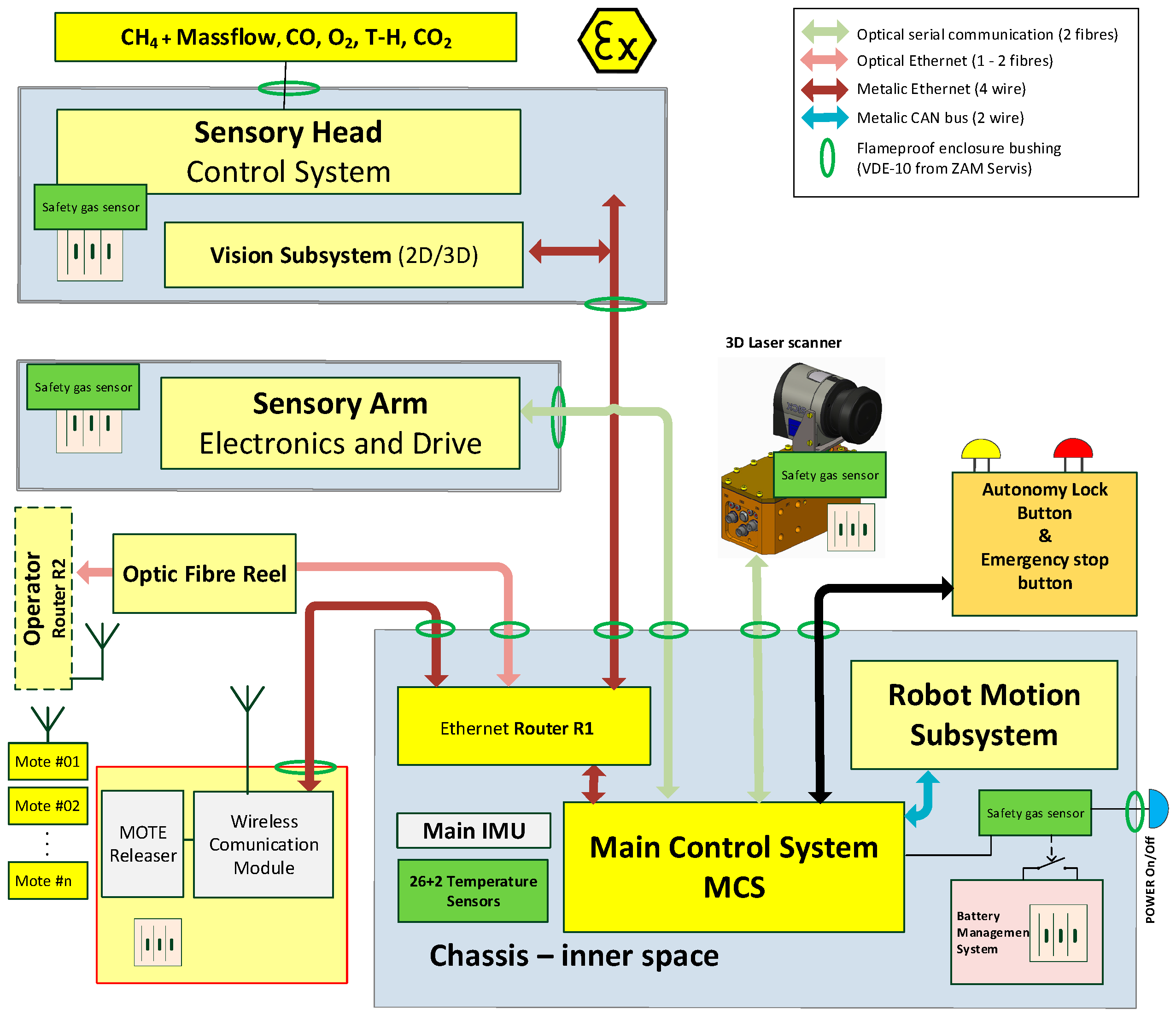
4.4. Separation of Subsystems

For increased safety, the mobile robot is divided into several galvanic isolated parts (depicted as grey boxes in Figure 6). Each of these subsystems has its own batteries and a safety methane detector (described in further chapters). The subsystems communicate over the optic fibre serial line (RS232) or Ethernet with galvanic isolated transformers.

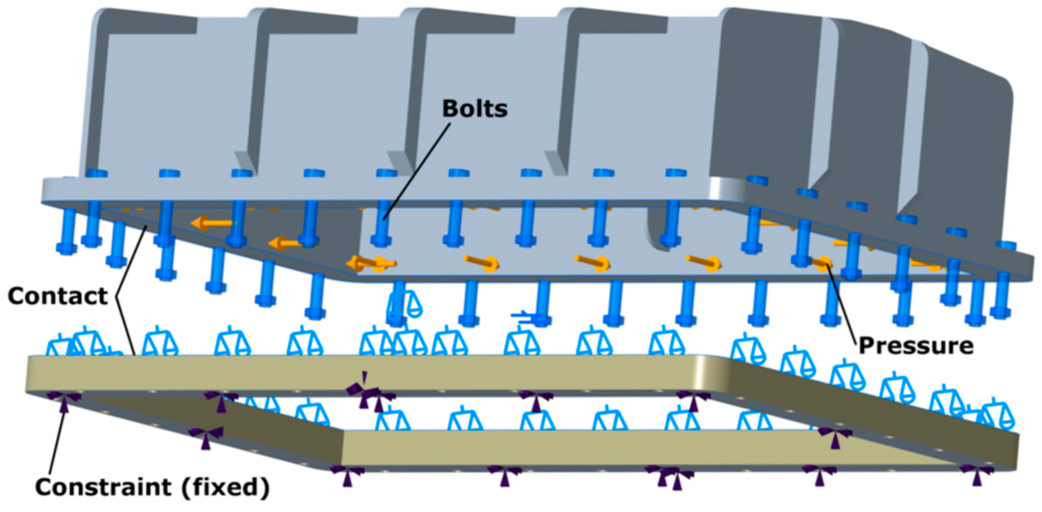
4.5. Flameproof Enclosure

The requirements resulting from the standards place big demands on the design of the covers of the individual components of the robot. The most important is the encapsulation of the robot body, which houses eight robot motors, a battery subsystem, and the main control system. The design requirements are based on standard EN 60079-1—Explosive atmospheres—Part 1: Equipment protection by flameproof enclosure “d” [30], which specifies requirements for wall thickness, strength and resistance to the potential explosion of methane within the robot, contact surfaces of detachable parts, etc.
In designing the shape of the robot encapsulation, strength analyses of individual parts were performed continuously to achieve the optimal shape, strength, and weight ratio with respect to the potential pressure that could cause methane explosion inside the robot body. These analyzes were performed in the PTC Creo Simulate 3.0 CAD system, more details about the methodology can be found in [31]. The following example will demonstrate inspection and optimization of the top cover under which the robot control system is located inside the body (Figure 4 and Figure 7).
In order to verify and optimize the top cover, it was necessary to create a computational model. The model contains a simplified assembly of the frame and the cover, with a contact between them. The frame is fixed and the cover is connected by screws, which are simulated as idealized Fastener elements (Figure 8). Based on the specification, the material “Stainless Steel 1.4462” was used for calculations (tensile strength Rm = 950 MPa, proof stress Re = 500 MPa).
A pressure of 3 MPa was applied on the inner surfaces of the cover. This value simulates the explosion of methane inside the robot body and it is based on experiments from [32,33], increased by a safety factor. Results of the analysis are shown in the following figures.
Figure 9 shows the stress distribution on the cover. The red areas represent stress peaks reaching up to 1900 MPa, which means that the cover could be seriously damaged by the explosion and the flameproof enclosure protection could be broken. It was thus necessary to modify the design on the cover to lower the stress peaks.
The final modified design of the cover is shown in Figure 10. The stress peaks are between 580 and 650 MPa, which does not exceed Rm and the cover would not be destroyed.
Another very important test is for any possible gaps between individual parts of the enclosure caused by the inner explosion. The maximum gap size is controlled by EN 60079-1 ([29]: table “Minimum width of joint and maximum gap for enclosures of Groups I, IIA and IIB”), which in the case of a planar gap with the length bigger than 25 mm (the actual gap length is 30 mm, see Figure 11) and inner volume larger than 2000 cm3 (the actual volume is approx. 40,000 cm3) allows for a maximum width of the gap 0.5 mm for Group I.
The simulation results show that the contact surface between the top cover and the bottom frame deforms during the explosion and a gap appears. The width of this gap is different on the inner and outer edge of the cover and changes with the position along the edge (Figure 11 and Figure 12), but it never exceeds the allowed limit (the maximum is 0.474 mm, which is less than 0.5 mm).

4.6. Automatic Safety Gas Detector

Even with the presence of methane in the atmosphere around the robot, methane should not get through the flameproof enclosure into the robot body. If, however, the enclosure is damaged, the second level of protection—automatic safety gas detector—prevents an explosion by turning the power of the whole robot off (except for the gas detector itself, which is designed with intrinsic safety) [34].
The design of the safety gas detector has a high safety level. It is purely hardware based (no microcontrollers and software), starting with an ATEX M1, SIL1, 0–5% v/v CH4 sensor from Dynament. The output of the sensor is per the British Mining Standards, 0.4–2 V. Two independent under-voltage and over-voltage comparators are connected to sensor output through high-value resistors, to avoid crossed-comparator fails—see Figure 13. Each comparator energises a relay, and the contacts of these relays are connected in series. Under-voltage (V < 0.4 V) is interpreted as sensor failure. Over-voltage is interpreted as CH4 > 0.5%. In both cases, power is disconnected by relays. Even if one comparator fails, the other will open the circuit. Intrinsically safe power supplies with appropriate voltage levels are included in the design of the safety gas monitor. The design is intentionally non-self-resetting. If the relays trip, it will remain de-energized until the arming (or re-arming) switch is operated. This feature is also used for avoiding draining the battery during long-term storage.
The detector also provides a logical signal for the main control system, which acts as a warning about an imminent power-down because of increased methane concentration. This allows for the control system to switch off in a controlled manner and primarily to disable DC motor drives to lower the currents for safer power-off switching. After a short delay, the logical signal is followed by power-down of the whole system.
The same automatic safety gas detector is installed separately in the main robot body, in the sensory arm and the sensory head; and a similar system is implemented also in the 3D LIDAR. The safety gas sensor is a part of the power management system, which distributes power from the batteries. The command for switching power off can come from several sources:
  • manual control of the power of the whole system (the main power on/off button),
  • manual activation of the safety central stop button,
  • command from the operator control system (safety central stop button on the operator panel),
  • the dangerous concentration of methane detected inside the subsystem, and
  • activation of an independent watchdog monitoring the embedded control system.
The methane detector was tested in atmosphere that contained methane and other gases in well-known amounts in a special gas chamber. A calibrated gas sensor Draeger X-am 5000 (reference) and the methane detector were closed inside the chamber with gas entry for methane mixture and a small hole for cable harness and to allow a small airflow. Figure 14 shows one of the graphs that were obtained during the testing after calibration, where the measured values closely match values from the reference sensor.

4.7. Other Protections

The two main independent protections mentioned above (mechanical protection—flameproof enclosure; electrical protection—automatic methane detector) are supplemented by many different partial protections.
All electronic components of the main control system are sealed with a compound according to IEC 60079-18 (Explosive atmospheres—Part 18: Equipment protection by encapsulation “m”) [35]. All cables leading outside of the flameproof enclosure are going through certified flameproof enclosure bushings.
In critical parts of the robotic system are installed thermometers that continuously monitor temperatures and allow for the control system to turn the robot off in case of unexpected overheating of some components.
The regulations also preclude the use of some types of materials for construction of the robot—for example, all light metal alloys (aluminium, titanium…). Plastic components pose a threat because of static charge and are thus allowed only with special precautions—the maximal continuous surface area of plastic without grounding is limited. All mechanical parts of the mobile robot TeleRescuer are made from steel, rubber (tracks), and glass (camera lenses covers).

5. Conclusions

A completely functional prototype of the reconnaissance mobile robotic system TeleRescuer has been built and thoroughly tested in various simulated and real conditions, including a training coal mine Queen Luiza in Zabrze, Poland—Figure 15. Tested were driving abilities (on various terrain material and quality, over obstacles of various sizes and shapes—perpendicular and at an angle, slalom, incline surfaces etc.), power abilities (pulling/pushing an obstacle), sensors accuracy, cameras placement, and image quality, etc. The tests showed some minor problems that should be improved in the following versions of the robot, for example, insufficient traction between the tracks and the ground, and complicated maneuverability in tight spaces during remote control based only on camera images. A detailed report from the tests is available in [36].
Explosion safety is ensured by two independent protections according to Technical Report CLC/TR 60079-33 “s”. The first protection is a flameproof enclosure that prevents methane from getting inside the body of the mobile robot. If this protection is damaged and a dangerous concentration of methane forms inside the body, the second protection (automatic gas detector) disconnects power from all electronic systems. This combination is valid for Group I, Category M1 because the whole system is fully operational even in environments with methane concentration and turns off only when the first protection is breached.
The proposed solution of explosion safety was evaluated by a specialized certification authority (OBAC Institute for Research and Certification Ltd., Gliwice, Poland) and several minor modifications were recommended in the evaluation report, but the overall concept was approved. The outcome of this process was, however, only a qualified opinion, the robot was not officially certified for explosion safety yet (the certification is very expensive and getting a full certification was not one of the goals of the project). Physical destructive tests of the flameproof enclosure (Section 4.3) were not performed at this stage.
The process of designing such a complex system (a reconnaissance mobile robot) in conformity with the very strict regulations that are related to explosion safety proved to be very difficult and demanding. It is highly recommended to discuss partial steps and decisions regularly during the process with a specialized authority.
Future work on the system will include implementation of the proposed minor modifications and improvements of construction of the robot, control system algorithms, and user interface regarding observations and feedback achieved during the final tests.

Author Contributions

Conceptualization, P.N., T.K. and J.B.; Data curation, Z.K.; Formal analysis, Z.K.; Funding acquisition, W.M.; Methodology, A.R.L.; Project administration, P.N. and W.M.; Software, T.K.; Supervision, P.N.; Validation, P.N.; Visualization, T.K.; Writing—original draft, P.N., T.K., J.B. and A.R.L.; Writing—review & editing, P.N. and T.K.

Funding

The project has been carried out in a framework of an EU programme of the Research Fund for Coal and Steel under the grant agreement No. RFCR-CT-2014-00002, by Polish Ministry for Science and Higher Education from financial sources that constitute the public aid in years, 2014–2017 assigned for an accomplishment of an international co-financed project; and partly supported by the European Regional Development Fund in the Research Centre of Advanced Mechatronic Systems project, project number CZ.02.1.01/0.0/0.0/16_019/0000867 within the Operational Programme Research, Development and Education.

Conflicts of Interest

The authors declare no conflict of interest.

References

  1. Wikipedia. Mining Accident. Available online: https://en.wikipedia.org/wiki/Mining_accident (accessed on 3 July 2018).
  2. The National Institute for Occupational Safety and Health. Coal Mining Disaster: 1839 to Present. Available online: https://www.cdc.gov/niosh/mining/statistics/content/coaldisasters.html (accessed on 3 July 2018).
  3. Moczulski, W.; Cyran, K.; Januszka, M.; Novak, P.; Rodriguez, A. System for Virtual Teleportation of Rescuer for Inspecting Coal Mine Areas Affected by Catastrophic Events; Technical Annex of the Project Application; Silesian University of Technology: Gliwice, Poland, 2014. [Google Scholar]
  4. Yang, D.; Wang, L.; Chen, J. The basic safety requirements of the coal mine rescue robot. Coal Mine Saf. 2009, 42, 104–107. [Google Scholar]
  5. EUR-Lex. Directive 2014/34/EU of the European Parliament and of the Council. Available online: https://eur-lex.europa.eu/legal-content/En/TXT/?uri=CELEX:32014L0034 (accessed on 9 July 2018).
  6. Czech Office for Standards, Metrology and Testing. ČSN EN 60079-0 ed. 4. Explosive atmospheres—Part 0: Equipment—General Requirement; Czech Office for Standards: Prague, Czech Republic, 2013; p. 100. [Google Scholar]
  7. CNEX-Global. Chinese Ex Product Certification. Available online: http://www.cnex-global.com/services/chinese-ex-product-certification.html (accessed on 3 July 2018).
  8. Petzl. Explosive Environments: HAZLOC Standard. Available online: https://www.petzl.com/BE/en/Professional/Explosive-environments--HAZLOC-standard (accessed on 3 July 2018).
  9. Certification of Conformity & Industrial Safety. Technical Regulations CU TR 012/2011 on the Safety of Equipment in Explosion Hazardous Environments—Certification and Declaration of Conformity. Available online: http://www.ccis-expertise.com/en/technical-regulations-cu-tr-012-2011-on-safety-of-equipment-in-explosion-hazardous-environments (accessed on 3 July 2018).
  10. New South Wales Government. Coal Mine Health and Safety Act 2002 No. 129. Available online: https://legislation.nsw.gov.au/#/view/act/2002/129 (accessed on 11 July 2018).
  11. Compilation of Regulatory Approaches Used in Various Countries. Available online: https://www.unece.org/fileadmin/DAM/trade/wp6/SectoralInitiatives/EquipmentForExplosiveEnvironment/SIEEE-QuestionsRepliesE.pdf (accessed on 11 July 2018).
  12. Ray, D.N.; Majumder, S.; Maity, A.; Roy, B.; Karmakar, S. Design and development of a mobile robot for environment monitoring in underground coal mines. In Proceedings of the 2015 Conference on Advances in Robotics, Goa, India, 2–4 July 2015; ISBN 978-1-4503-3356-6. [Google Scholar]
  13. Gomathi, V.; Sowmeya, S.; Avudaiammal, P.S. Design of an Adaptive Coal Mine Rescue Robot using Wireless Sensor Networks. Int. Comput. Appl. 2015, 2, 8–11. [Google Scholar]
  14. Ma, X.; Mao, R. Path Planning for Coal Mine Robot to Avoid Obstacle in Gas Distribution Area. Int. J. Adv. Robot. Syst. 2018, 15. [Google Scholar] [CrossRef]
  15. Wang, W.; Dong, W.; Su, Y.; Wu, D.; Du, Z. Development of search-and-rescue robots for underground coal mine applications. J. Field Robot. 2014, 31, 386–407. [Google Scholar] [CrossRef]
  16. Jonathon, C.R.; David, W.; Hainsworth, A. The numbat: A remotely controlled mine emergency response vehicle. In Field and Service Robotics; Springer: London, UK, 1998; pp. 53–59. ISBN 978-1-4471-1273-0. [Google Scholar]
  17. United States Department of Labor. MSHA-Wolverine Robot. Available online: https://arlweb.msha.gov/sagomine/robotdetails.asp (accessed on 10 July 2018).
  18. Sandia National Laboratories. Gemini-Scout Mine Rescue Vehicle. Available online: http://www.sandia.gov/research/ robotics/unique_mobility/gemini-scout.html (accessed on 10 July 2018).
  19. Kasprzyczak, L.; Szwejkowski, P.; Cader, M. Robotics in Mining Exemplified by Mobile Inspection Platform. Min. Inf. Autom. Electr. Eng. 2016, 2, 23–28. [Google Scholar]
  20. TeleRescuer. Available online: http://www.telerescuer.polsl.pl (accessed on 3 July 2018).
  21. Department of Robotics, TeleRescuer. Available online: http://robot.vsb.cz/telerescuer/ (accessed on 3 July 2018).
  22. Babjak, J.; Novák, P.; Kot, T.; Moczulski, W.; Adamczyk, M.; Panfil, W. Control System of a Mobile Robot for Coal Mines. In Proceedings of the 2016 17th International Carpathian Control Conference (ICCC), Tatranska Lomnica, Slovakia, 29 May–1 June 2016; pp. 17–20, ISBN 978-146738606-7. [Google Scholar]
  23. Novak, P.; Babjak, J.; Kot, T.; Bobovský, Z.; Olivka, P.; Moczulski, W.; Timofiejczuk, A.; Adamczyk, M.; Guzman, B.G.; Armada, A.G.; et al. Telerescuer—Reconnaissance mobile robot for underground coal mines. In Proceedings of the 2017 Coal Operators’ Conference, Wollongong, Australia, 8–10 February 2017; The University of Wollongong Printery: Wollongong, Australia, 2017; pp. 332–340, ISBN 978-1-74128-261-0. [Google Scholar]
  24. Olivka, P.; Mihola, M.; Novák, P.; Kot, T.; Babjak, J. The 3D laser range finder design for the navigation and mapping for the coal mine robot. In Proceedings of the 17th IEEE International Carpathian Control Conference (ICCC), Tatranska Lomnica, Slovakia, 29 May–1 June 2016; pp. 533–538, ISBN 978-146738606-7. [Google Scholar]
  25. Kot, T.; Novák, P.; Babjak, J. Visualization of Point Clouds Built from 3D Scanning in Coal Mines. In Proceedings of the 17th IEEE International Carpathian Control Conference (ICCC), Tatranska Lomnica, Slovakia, 29 May–1 June 2016; pp. 372–377, ISBN 978-146738606-7. [Google Scholar]
  26. Kot, T.; Novák, P.; Babjak, J.; Olivka, P. Rendering of 3D Maps with Additional Information for Operator of a Coal Mine Mobile Robot. In Modelling and Simulation for Autonomous Systems MESAS 2016; Lecture Notes in Computer Science; Springer: Berlin, Germany, 2016; Volume 9991, pp. 214–225. [Google Scholar]
  27. Kot, T.; Novák, P.; Babjak, J. Virtual Operator Station for Teleoperated Mobile Robots. In Proceedings of the International Workshop on Modelling and Simulation for Autonomous Systems (MESAS), Prague, Czech Republic, 29–30 April 2015; pp. 144–153, ISBN 978-3-319-22383-4. [Google Scholar]
  28. Arena, P.; Fortuna, L.; Frasca, M.; Patané, L. Learning Anticipation via Spiking Networks: Application to Navigation Control. IEEE Trans. Neural Netw. 2009, 20, 202–216. [Google Scholar] [CrossRef] [PubMed] [Green Version]
  29. IEC Webstore. IEC 60079-33:2012 Explosive Atmospheres—Part 33: Equipment Protection by Special Protection ‘S’. Available online: https://webstore.iec.ch/publication/652 (accessed on 9 July 2018).
  30. Czech Office for Standards, Metrology and Testing. ČSN EN 60079-1 ed. 3. Explosive Atmospheres—Part 1: Equipment Protection by Flameproof Enclosure "d"; Czech Office for Standards: Prague, Czech Republic, 2015; p. 68. [Google Scholar]
  31. Konečný, Z. Evaluating Methods of the Strength Analyzes Results Realize in PTC Creo/Simulation. Appl. Mech. Mater. 2015, 816, 357–362. [Google Scholar] [CrossRef]
  32. Górny, M. Explosion Pressure Inside Flameproof Electrical Motors in Low Temperatures. Zeszyty Problemowe Maszyny Elektryczne 2008, 80, 99–105. [Google Scholar]
  33. Górny, M. Gas Explosion Propagation Through Flameproof Induction Motor’s Air Gap. Zeszyty Problemowe Maszyny Elektryczne 2013, 99, 121–127. [Google Scholar]
  34. Czech Office for Standards, Metrology and Testing. ČSN EN 60079-11 ed. 2. Explosive Atmospheres—Part 11: Equipment Protection by Intrinsic Safety “i”; Czech Office for Standards: Prague, Czech Republic, 2012; p. 132. [Google Scholar]
  35. Czech Office for Standards, Metrology and Testing. ČSN EN 60079-18 ed. 3. Explosive Atmospheres—Part 18: Equipment Protection by Encapsulation “m”; Czech Office for Standards: Prague, Czech Republic, 2015; p. 36. [Google Scholar]
  36. Kopex Group. Report on Field Tests of TeleRescuer System [Final Report]. 2018. Available online: http://www.telerescuer.polsl.pl/ (accessed on 2 November 2018).
Figure 1. Minibot-II robotic platform (left), Robot Numbat (right).
Applsci 08 02300 g001
Figure 2. Wolverine V-2 robot developed by Remotec (left) and Gemini-Scout (right).
Applsci 08 02300 g002
Figure 3. MPI robot by Emag-Piap consortium (Poland).
Applsci 08 02300 g003
Figure 4. TeleRescuer—main subsystems.
Applsci 08 02300 g004
Figure 5. TeleRescuer—cameras and lights on the sensory head.
Applsci 08 02300 g005
Figure 6. Separation of TeleRescuer subsystems.
Applsci 08 02300 g006
Figure 7. Main robot body with the top cover.
Applsci 08 02300 g007
Figure 8. Computational model of the top cover assembly.
Applsci 08 02300 g008
Figure 9. Stress distribution during an explosion simulation (initial design).
Applsci 08 02300 g009
Figure 10. Stress distribution during an explosion simulation (final design).
Applsci 08 02300 g010
Figure 11. Top cover deformation.
Applsci 08 02300 g011
Figure 12. Gap width (for the inner and outer edge) in relation to a position along the edge (the local maxima correspond to ribs on the cover).
Applsci 08 02300 g012
Figure 13. Implementation of safety gas detector into the robot subsystems—simplified diagram.
Applsci 08 02300 g013
Figure 14. Safety methane detector testing (CH4 concentration [%] over time [s] in a testing chamber).
Applsci 08 02300 g014
Figure 15. TeleRescuer—testing in a training coal mine Queen Luiza (March 2018).
Applsci 08 02300 g015

