Abstract
This paper was on the forming characteristics of AZ 31B Mg alloy in a combined forward–backward extrusion (CFBE) at warm temperatures. Both experimental studies and thermomechanical finite element analyses were performed. A finite element analysis model coupled with damage evolution was presented. Based on our previous work, the forward extrusion ratio, backward extrusion ratio, forming temperature, and punch speed were chosen as the most important process parameters. Two punch speeds of 2 mm/s and 20 mm/s were examined for the forming temperatures of 180 °C and 200 °C. Forward extrusion ratios were 2.25, 4.0, and 9.0, while backward extrusion ratios were 1.33, 2.16, 4.02, and 7.75. Effects of those parameters on the forming limit, deformation behaviors, extrusion load, and the mechanical properties of an extruded product were discussed in detail.
1. Introduction
Environmental pollution and global warming forced many countries in the world to set regulations to improve the life of human beings. Specifically, exhaust fumes by an automobile were cited as one of the reasons for environmental pollution and global warming. The demand to increase fuel efficiency becomes an issue because of the problem of finite resources. To increase fuel efficiency, it is better to reduce the vehicles deadweight. When the weight of an automobile decreases by 10%, its fuel efficiency could increase by about 5 to 10%. There have been many attempts to replace the heavy steel parts of vehicles with new materials that are light weight and have high strength, such as Magnesium alloys [1,2,3,4,5]. Magnesium alloy has a 1.74 g/cm3 density which is two-thirds of aluminum alloy, one-third of titanium, and one-fourth of steel. Moreover, magnesium alloys have good machinability, superior dent resistance, and excellent vibration damping properties. Thus, magnesium alloy has been studied as a new light material for automobile parts. Nevertheless, its extended applications are limited by its low formability at room temperature [6,7]. Its low formability is due to its hexagonal close packed crystal structure, which has less slip systems to yield applied external deformation. Traditionally, Mg alloy products have been made mostly by casting or semi-solid die casting. However, casting and semi-solid die casting inherently have a weak point of air pollution, defects of casting, and poor surface quality. Poor formability and easy oxidation of Mg alloys create requirements for delicate process conditions for successful forming.
Although many researches were carried out to improve forming technology of Mg alloys [8,9,10,11,12,13,14,15,16,17,18], further research is still needed to understand forming characteristics of Mg alloys during bulk forming process such as extrusion or rolling. For instance, hydrostatic extrusion was utilized to increase the formability of AZ 31 Mg alloys by reducing damage evolution under high pressure [8,9]. Many previous works focused on the examination of microstructural developments and corresponding mechanical property changes during the bulk forming of AZ31 Mg alloys [10,11,12,13,14,15,16,17,18]. Among them, Yoon et al. [10,11,12,13] reported that the forming temperature for bulk forming processes such as forging and extrusion, is very influential. It was also shown that the backward extrusion of Mg alloys at warm temperatures was very successful when forming a cup-shaped product. They also reported the localized deformation behaviors observed near the punch corner and the inside of the lower die with micro structure investigation [13]. More recently, some research has presented improvements to the mechanical properties and formability of Mg alloys by examining extrusion conditions [14] or by adding other elements [15,16,17].
Some cup-rod shaped automobile parts, having the cup-shaped side with the other rod-shaped side, could be formed using the Combined Forward–Backward Extrusion (CFBE) process with AZ Mg alloys [12] and with aluminum alloys [18]. Figure 1 is a schematic drawing of a typical CFBE process, which shows some material flows. As the punch advances, the main material flows are in two opposite directions with a divergence point. Such complicated metal flows in the CFBE process require delicate process conditions for a successful CFBE. The current authors examined microstructural changes in a CFBE process of AZ31B Mg alloys at warm temperatures [13], and found that further studies would be needed to figure out the process conditions for a successful process. This study was a continuation of our previous work, wherein, in this study, both experimental studies and finite element studies were carried out. In addition, the forming temperature, forward extrusion ratio (FER), backward extrusion ratio (BER), and punch speed were chosen as important process parameters based on previous work. Effects of such process parameters on the forming characteristics, including the forming limit, deformation behavior, extrusion load, and mechanical properties of the extruded product, were systematically examined.
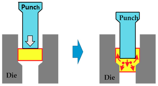
Figure 1.
A schematic drawing of combined forward–backward extrusion.
2. Experiments
The specimen used in this work was a AZ31B Mg alloy, where its chemical compositions are given in Table 1. To enforce the uniform mechanical property of a specimen in experiments, the homogenization treatment was performed by holding the AZ31B Mg alloy specimen at 400 °C for 10 h, and then cooling it in the furnace. A specimen was prepared by machining, such that its height and diameter were 29.7 mm and 20 mm, respectively. Molybdenum disulfide, MoS2, was selected as a lubricant. To obtain the punch speed of 2 mm/s and 20 mm/s, a 90 ton press was utilized.

Table 1.
Chemical composition of magnesium alloy AZ31B Mg alloy. (wt %).
In the case of a CFBE process with an AZ 31B Mg alloy, the forming temperature is the most important process parameter to increase formability. In this study, two forming temperatures, 180 °C and 200 °C, were considered, and both the specimen, punch, and die were heated up to the forming temperature.
It also should be noted that the important parameters in designing punch and dies for a CFBE process are the die angle and die corner radius for the forward extrusion. Further systematic studies on those parameters might be required. Based on our preliminary experiments, a half die angle and corner radius of the forward extrusion die were determined as 80 degree and 0.5 mm, respectively. Geometric parameters used in this work are shown in Figure 2, whilst detailed experimental conditions are summarized in Table 2.
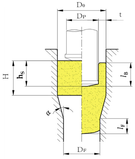
Figure 2.
Geometrical parameters in a Combined Forward–Backward Extrusion (CFBE) process.
Table 2.
Experimental conditions for CFBE of AZ31B Mg alloy.
3. Finite Element Analysis Coupled with Damage Evolution
The CFBE process has some advantages, since it forms a cup-rod shaped part effectively. However, CFBE processes induce complicated material flows due to the opposing directions of extruded material flows, as shown in Figure 1. Such material flows in a CFBE are a mutually restraining and unsteady state. Thus, it is not easy to understand deformation behaviors during a CFBE process, as well as defining the process conditions for a successful CFBE process.
Thermomechanical finite element analysis may aid in understanding the deformation characteristics of AZ31 Mg alloys during the forming process at an elevated temperature, especially the deformation behaviors inside a work piece that could not be observed in experiments. In this work, the elastic behavior of AZ 31 Mg ally at warm temperatures was so small that it was neglected. Its inelastic behavior at warm temperatures was assumed as hardening and viscoplastic. Since the finite element formulation for the hardening, rigid viscoplastic deformation has been reported previously in References [19,20], its detailed procedure was not given in this study. Here, a common finite element package DEFORM 2D [19] was used for the thermomechanical finite element analysis of AZ31 Mg alloy at warm temperatures.
Damage in this work was defined as a void volume fraction or porosity, since AZ31 Mg alloy has moderate ductility at warm temperatures. Yoon et al. [21] reported the comparisons of four damage evolution models by Cockcroft et al. [22], Brozzo et al. [23], Oyane [24], and Lee and Dawson [25], for the analysis of damage evolution in pure shear and backward extrusion of AZ31 Mg alloy. In the damage evolution model by Lee and Dawson, the mean stress was scaled by a hardness (), which represents the rate-independent limit of the hardening state, whilst the mean stress was scaled by flow stress in all others. Yoon et al. [21] concluded that the model proposed by Lee and Dawson could predict damage evolution in extrusion better than the other models, especially for complicated deformation, including severe shear deformation. The first reason is that the exponential function with a ratio of mean stress, with respect to a flow stress, would overestimate for the damage evolution when the flow stress is low. The second reason is that the damage models, except for one by Lee and Dawson, were unable to capture accurately the effects of shear deformation on the damage evolution. The detailed explanation on the comparison is given in the Reference [21]. The damage evolution model by Lee and Dawson is coupled with DEFORM 2D through a user subroutine, which is given by the following equation.
where is a damage variable, defined as a porosity in this work. and are the mean stress and hardness, respectively. In general, is greater than a yield stress. Here, material constants, and , were used, which were obtained by fitting a tensile test or compression test until fracture. In this study, 0.0011 was taken as the initial value of following the recommendation for engineering materials in Reference [20]. Thermomechanical finite element simulation conditions for a CFBE process of AZ 31 Mg alloy were taken from the experimental conditions given in the previous section. In the following simulations, punch and dies were treated as rigid as usual, since they are extremely hard, and their elastic deformation is negligible.
4. Results and Discussions
The main object of the forming process is to form a product with the shape and dimensions as designed without any damage. First, we examined forming limits, as well as deformation behavior, of the AZ31B Mg alloy during a CFBE process at warm temperatures. To design a CFBE process, determination of the required extrusion load was necessary. Thus, the effects of process conditions, such as punch velocity, forming temperatures, and extrusion ratios on the extrusion loads were examined. In this study, both the Forward Extrusion Ratio (FER) and Backward Extrusion Ratio (BER) were independently varied. Finally, the effects of process conditions on the distribution of hardness in an extruded product were given.
4.1. Forming Limits and Deformation Behavior
Effects of forming temperature and punch speed on forming limits for FEB = 9 and BER = 4.02 are shown in Figure 3. Figure 3a,b show extruded specimens at the forming temperatures of 180 °C and 200 °C, respectively. The specimens (a-1) and (a-2) in Figure 3a were obtained under the punch speed of 2 mm/s and 20 mm/s, respectively. Both specimens showed fractures in the forward extruded parts. On the other hand, the specimens (b-1) in Figure 3b showed minor fractures in the forward extruded part, as in Figure 3a, whilst specimen (b-2) under the punch speed of 20 mm/s does not have any defects. Thus, the elevated forming temperature of 200° C could result in less severe process conditions for a successful operation. As for the effects of punch speed, more plastic work dissipation under the punch speed of 20 mm/s would increase formability of the AZ31B Mg alloy. This is because the temperature of the work piece could increase due to plastic work dissipation from the high plastic deformation with increased punch speed.
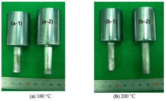
Figure 3.
Extruded specimens at the forming temperature of (a) 180 °C and (b) 200 °C under the punch speed of (1) 2 mm/s, (2) 20 mm/s for FER = 9.0 and BER = 4.02.
Deformation behaviors were examined for the CFBE process of AZ31B alloy using thermomechanical finite element analysis coupled with damage evolution. In this study, typical deformation behaviors were given specifically for the CFBE process under the forming temperature of 200 °C, punch speed of 2 mm/s, and FER = 2.25. Figure 4 shows the distributions of effective stress (Figure 4a), effective strain rate (Figure 4b), effective strain (Figure 4c), and temperature (Figure 4d), for three different BER’s of 2.16, 4.02, and 7.75.
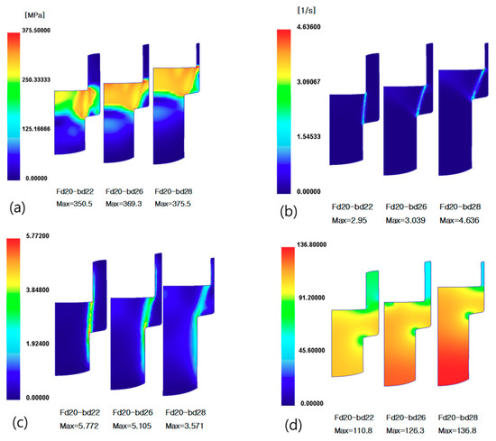
Figure 4.
Distribution of (a) effective stress; (b) effective strain rate; (c) effective strain; and (d) temperature predicted by finite element analyses for the CFBE processes of AZ31B Mg alloy.
As shown in Figure 4a, effective stresses become bigger as the BER gets larger. It can be explained as follows: The metal flow into the forward direction becomes large, since the exit area in the backward direction becomes small due to a large BER. Therefore, the effective stress near the punch corner becomes large. Distributions of effective strain rate and strain in Figure 4b,c show shear bands from the punch corner to the die corner. In general, ductile damage develops fast when the mean stress is large. Moreover, high shearing deformation amplifies such damage evolution. Thus, such shear bands could be the source of damage evolution and eventual fracture. As shown in Figure 4d, temperature in an extruded work piece becomes higher as BER gets larger, since a high BER induces more plastic work dissipation than the others as expected.
The distribution of accumulated damage predicted by finite element analysis for the above process conditions is given in Figure 5. Additionally, the photo of the extruded products in experiments under the same process conditions is given in Figure 5, which was reported in the literature [13]. Finite element simulation predicts high values of accumulated damage in the shear band zone, and also near the surface of the forwardly extruded part. This is because more material in the shear band zone flows in the forward direction as a punch advances, especially when FER is low, such as at 2.25. The extruded work pieces for BER of 2.16 and 4.02, are shown in the photo in Figure 5b,c, where it shows some defects at the surface of the forwardly extruded part. When the finite element predictions on the accumulated damage were compared to the experimental observations under the same process conditions, the current finite element predictions matched very well with the experiments qualitatively. To accurately compare them, a critical damage or a criterion is required, which can identify the initiation of fracture in an extruded work piece. Such further work on critical damage is left for the future.
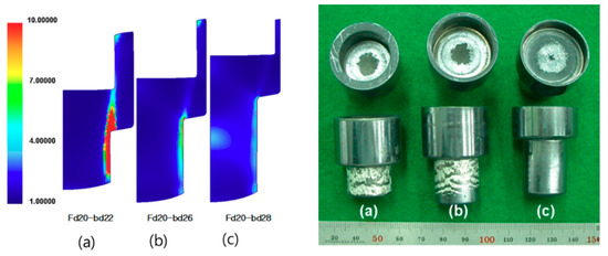
Figure 5.
Distribution of predicted damage and experiments, described in Reference [13] for BER of (a) 2.16; (b) 4.02; (c) 7.75 under the punch speed of 2 mm/s and temperature of 200 °C.
4.2. Extrusion Loads
In the CFBE process of AZ31B Mg alloys, the important process parameters affecting the extrusion loads are forming temperature, punch velocity, and the forward–backward extrusion ratio. First, the effects of temperature on the extrusion loads were examined. Figure 6 shows the variation of punch load along a punch stroke that is obtained from the CFBE experiments under the punch speed of 2 mm/s, FER = 2.25, and BER = 7.75. As expected, the punch load increases rapidly at the beginning stage of the CFBE process and decreases slowly after its maximum value. This maximum punch load is often called the extrusion load. As shown in Figure 6, the extrusion load at the forming temperature of 200 °C is lower than that at 180 °C. The increase of forming temperature induces a lower flow stress, and it correspondingly reduces the punch load required for a CFBE process.
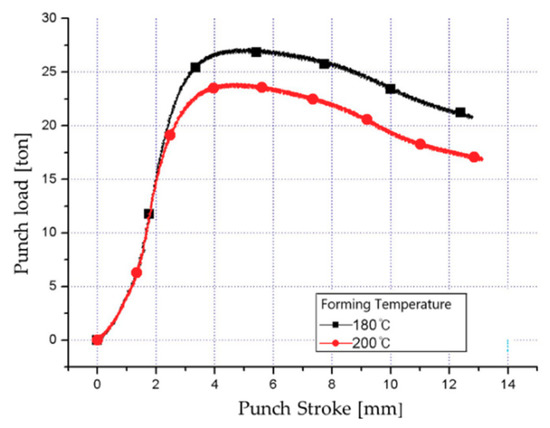
Figure 6.
Effects of temperature on the punch loads. (Punch speed = 2 mm/s, FER = 2.25, BER = 7.75).
Although the effects of punch speed on the extrusion loads are not shown in this paper, the increase of punch velocity from 2 mm/s to 20 mm/s reduces the extrusion load slightly. It can be explained as follows: The plastic work dissipation rate increases as the deformation rate increases from the high punch speed. Such high plastic work dissipation induces the increase of work piece temperature, and then reduces the flow stress. There is a little increase in flow stress due to the strain-rate dependency of AZ31B Mg alloy, but this increase in flow stress is less than the decrease in flow stress due to the temperature increase by plastic work dissipation.
Figure 7 shows the variation of punch load along a punch stroke, obtained from the CFBE experiments under the punch speed of 20 mm/s, BER = 7.75, and forming temperature of 200 °C. Three FER values were considered in this case, and they were 2.25, 4.0, and 9.0. Again, the punch load increases rapidly at the beginning stage and decreases slowly after passing the maximum point of extrusion load. It seems natural that a high FER causes a large punch load. As a FER becomes larger, more material flows in the backward direction.
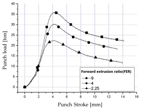
Figure 7.
Variation of punch loads along the punch stroke. (Temperature = 200 °C, BER = 4.02, and punch speed = 20 mm/s).
Figure 8 shows the comparisons between the extrusion loads by finite element analyses and by experiments for the various FER’s and BER’s under the forming temperature of 200 °C and punch speed of 20 mm/s. As the extrusion ratio becomes smaller, the deviation between the predictions and experimental measurements becomes slightly larger. However, the predicted extrusion loads matched those in the experiments well. Similar comparisons were observed for the punch speed at 2 mm/s, although it is not given here. It may be concluded that the finite element analysis coupled with damage evolution presented in this work is valid for modeling a CFBE process of AZ31B Mg alloys at warm temperatures.
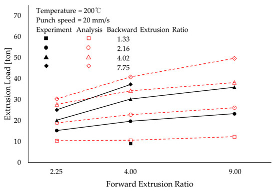
Figure 8.
Extrusion loads for various forward–backward extrusion ratios.
4.3. Hardness
In the experiments, Vickers hardness was measured on the cross section of the extruded specimen. Those hardness distributions are compared to the distributions of effective strain predicted by finite element analyses, for the same process conditions. Those comparisons are shown in Figure 9, for the process conditions of punch speed = 2 mm/s, FER = 2.25, and BER = 7.75, under the forming temperature of (a) 180 °C and (b) 200 °C. It is shown that the distribution of effective strain in Figure 9a for 180 °C is higher than that in Figure 9b for 200 °C. Such characteristics are the same as those in the distribution of Vickers hardness measured in the experiments. The Vickers hardness in the shear band zone was higher than that in the other zones. Such distribution was similar to that of effective strain by finite element analysis. The effective strain is known as being correlated to hardness. Again, it should be noted that the current finite predictions on effective strain would be useful in understanding the distribution of hardness.
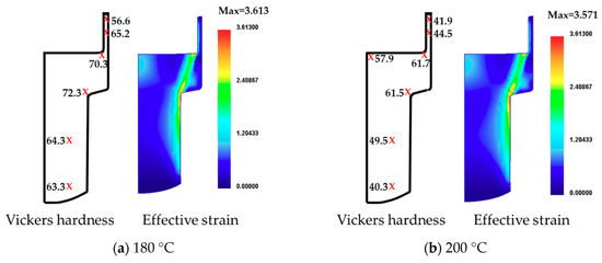
Figure 9.
Correlation between Vickers hardness and effective strain at the temperature of (a) 180 °C, (b) 200 °C. (Punch speed = 2 mm/s, FER = 4.0, BER = 4.02).
5. Conclusions
To examine the effects of process parameters on the forming characteristics of AZ31B Mg alloy in CFBE at warm temperatures, both experimental works and finite element studies were carried out. The viscoplastic finite element analysis coupled with the damage evolution model by Lee and Dawson [25] was introduced. Overall, the finite element predictions matched experimental observations, especially for the prediction of forming limits, extrusion loads, and distribution of hardness.
The forming temperature of 200 °C weakens the other process conditions, such as punch speed and extrusion ratios. In other words, the products extruded at 200 °C, had less defects than those at 180 °C. Accumulated damage predicted by the current finite element analyses would allow an engineer to estimate the possible fracture and its location.
The extrusion load increases as the forming temperature decreases, or as the punch speed decreases, or BER gets large. The distribution of Vickers hardness measured in the experiments was found to be correlated to the distribution of effective strain by the current finite element analysis.
Author Contributions
D.J.Y. and E.-Z.K. carried out the experiments and finite element simulations for the CFBE process of AZ31B Mg alloys; D.J.Y., E.-Z.K., K.H.N. and Y.-S.L. analyzed the data; Y.-S.L. wrote the paper and supervised all parts of this paper.
Funding
This research received no external funding.
Acknowledgments
D.J.Y. and E.-Z.K. would like to thank KITECH for their partial supports and appreciate Yoon Sang-Hun’s help in innumerable finite element simulations. Y.-S.L. is thankful for the support from Kookmin University.
Conflicts of Interest
The authors declare no conflict of interest.
References
- Roberts, C.S. Magnesium and Its Alloys; John Wiley: New York, NY, USA, 1960. [Google Scholar]
- Friedrich, H.; Schumann, S. Research for a new age of Mg in the automotive industry. J. Mater. Process. Technol. 2001, 117, 276–381. [Google Scholar] [CrossRef]
- Friedrich, H.E.; Mordike, B.L. Magnesium Technology—Metallurgy, Design Data, Applications; Springer: Basel, Switzerland, 2006. [Google Scholar]
- Watarai, H. Trend of research and development for magnesium alloys—Reducing the weight of structural materials in motor vehicles. Sci. Technol. Trends 2006, 18, 84–97. [Google Scholar]
- Beer, A.G. Advances in Wrought Magnesium Alloys; Woodhead Publishing: Oxford, UK, 2012. [Google Scholar]
- Doege, E.; Droder, K. Sheet Metal Forming of Magnesium Wrought Alloys–Formability and Process Technology. J. Mater. Process. Technol. 2001, 115, 14–21. [Google Scholar] [CrossRef]
- Ogawa, N.; Shiomi, M.; Osakada, K. Forming limit of Mg alloy at elevated temperatures for precision forging. Int. J. Mach. Tool Manuf. 2002, 42, 607–614. [Google Scholar] [CrossRef]
- Yoon, D.J.; Seo, Y.W.; Cho, C.; Choi, H.J.; Na, K. Characteristics of hydrostatic extrusion for AZ 31 Mg alloy. Advanced Technology of Plasticity. In Proceedings of the 8th ICTP, Verona, Italy, 9–13 October 2005. [Google Scholar]
- Bohlen, J.; Yi, S.B.; Swiostek, J.; Letzig, D.; Brokmeier, H.G.; Kainer, K.U. Microstructure and texture development during hydrostatic extrusion of magnesium alloy AZ31. Scr. Mater. 2005, 53, 259–264. [Google Scholar] [CrossRef]
- Yoon, D.J.; Na, K.; Cho, C. The microstructure of AZ31 magnesium alloy by forward extrusion with various extrusion parameter. Mater. Sci. Forum 2007, 539, 1818–1823. [Google Scholar] [CrossRef]
- Yoon, D.J.; Kim, E.-Z.; Lee, Y.-S. Finite Element Analysis on Deformation Characteristics and Damage Evolution in Warm Backward Extrusion of AZ31 Mg Alloys. Trans. Mater. Process. 2007, 16, 614–620. [Google Scholar]
- Yoon, D.J.; Kim, E.-Z.; Cho, C.; Lee, Y.-S. A process map for sequential compression-extrusion of AZ31 Mg Alloys at warm temperatures. Int. J. Mod. Phys. 2008, 22, 5649–5654. [Google Scholar] [CrossRef]
- Yoon, D.J.; Lim, S.J.; Jeong, H.G.; Kim, E.-Z.; Cho, C.D. Forming characteristics of AZ31B magnesium alloy in bidirectional extrusion process. J. Mater. Process. Technol. 2008, 115, 14–21. [Google Scholar] [CrossRef]
- Elsayed, F.R.; Sasaki, T.T.; Ohkubo, T.; Takahashi, H.; Xu, S.W.; Kamado, S.; Hono, K. Effect of extrusion conditions on microstructure and mechanical properties of microalloyed Mg-Sn-Al-Zn alloys. Mater. Sci. Eng. A 2013, 588, 318–328. [Google Scholar] [CrossRef]
- Alaneme, K.K.; Okotete, E.A. Enhancing plastic deformability of Mg and its alloys—A review of traditional and nascent developments. J. Magnes. Alloys 2017, 5, 460–475. [Google Scholar] [CrossRef]
- Kim, S.-H.; Bae, S.W.; Lee, S.W.; Moon, B.G.; Kim, H.S.; Kim, Y.M.; Yoon, J.; Park, S.H. Microstructural evolution and improvement in mechanical properties of extruded AZ31 alloy by combined addition of Ca and Y. Mater. Sci. Eng. A 2018, 725, 309–318. [Google Scholar] [CrossRef]
- Somekawa, H.; Kinoshita, A.; Kato, A. Effects of alloying elements on room temperature stretch formability in Mg alloys. Mater. Sci. Eng. A 2018, 732, 21–28. [Google Scholar] [CrossRef]
- Farhoumand, A.; Ebrahimi, R. Experimental investigation and numerical simulation of plastic flow behavior during forward-backward-radial extrusion process. Prog. Nat. Sci. Mater. Int. 2016, 26, 650–656. [Google Scholar] [CrossRef]
- Fluhrer, J. DEFORM™ 2D Ver. 8.0 User’s Manual; Scientific Forming Technologies Corporation: Columbus, OH, USA, 2008. [Google Scholar]
- Lee, Y.-S. An Eulerian Finite Element Model for the Steady State Forming of Porous Materials. Met. Mater. Int. 2006, 12, 161–166. [Google Scholar] [CrossRef]
- Yoon, S.H.; Lee, Y.-S.; Nam, W.; Park, K.; Yoon, D.J. Comparative study on damage evolution models. In Proceedings of the KSPE, Jeju Island, Korea, 18 May 2008. [Google Scholar]
- Cockcroft, M.G.; Latham, D.J. Ductility and the workability of metals. J. Inst. Met. 1968, 96, 33–39. [Google Scholar]
- Brozzo, P.; de Luka, B.; Rendina, R. A new method for the prediction of formability in metal sheets. In Proceedings of the 7th Biennial Conference on Sheet Metal Forming and Formability, Paris, France, 1–4 June 1972. [Google Scholar]
- Oyane, M. Criteria of ductile fracture strain. Bull. JSME 1972, 15, 1507–1513. [Google Scholar] [CrossRef]
- Lee, Y.-S.; Dawson, P.R. Modeling ductile void growth in hardening viscoplastic materials. Mech. Mater. 1993, 15, 21–34. [Google Scholar] [CrossRef]
© 2018 by the authors. Licensee MDPI, Basel, Switzerland. This article is an open access article distributed under the terms and conditions of the Creative Commons Attribution (CC BY) license (http://creativecommons.org/licenses/by/4.0/).