1. Introduction
During the last decades, the energy demand required to activate the conventional air-conditioning systems has increased due to the growing population. The countries with warm conditions need to use air-conditioning systems to achieve comfortable conditions [
1]. In the case of Mexico, this country has four climatic regions: arid, dry tropic, mild weather and humid tropic [
2]. In Mexico, 5.2 million air-conditioning units were installed in the Mexican households in 2011 [
3]. Thus, conditioned households were calculated to be 19.5% of the total, however, if it is considered the annual growing rate as 7.5% [
4], in 2015, the average number of households with air-conditioning devices was determined at 6.9 million. Therefore, the electricity demand estimated for air-conditioning was 11.8 TW/h in 2015, increased 2.9 TW/h with respect at 8.9 TW/h calculated in 2011 [
5]. This fact means that we must find an alternative option for mitigating the energy demand.
Solar energy is an alternative option because it is the most abundant energy source on earth. Thanks to its favorable geographic location, Mexico can use solar technologies [
6]. As a very convenient option. To take advance of solar energy, a wide range of solar collectors can be used, however, one of the more advanced technology is the parabolic trough collector (PTC) [
7]. Several authors have reported the performance of several air-conditioning systems driven by solar technologies, such as Li et al. [
8], who reported about the performance of LiBr-H
2O absorption chiller of 4.7 kW cooling capacity for a traditional and partitioned storage tank. The system was installed at the University of Hong Kong and employed a set of flat-plate collectors covering an area equivalent to 38 m
2 and a storage tank with a volume of 2.73 m
3. The results calculated COP was 0.07 (15% higher than traditional tank mode). Syed et al. [
9] evaluated a LiBr-H
2O absorption air-conditioning unit (35 kW) and 49.9 m
2 flat-plates collectors designed for cooling for a typical Spanish house. The results show the cooling effect was provided by 8.6 h, the maximum cooling capacity was 7.5 kW. The average COP was 0.6 during the period. Rodríguez et al. [
10] analyzed an experimental solar absorption cooling system installed at the University Carlos III in Madrid. The system consists of 50 m
2 flat plate solar collectors model Vitosol 100 coupled to a Yazaki absorption machine, it uses LiBr-H
2O. According to the results, the average cooling capacity was 3 kW during the summer season, the cooling period was 6.5 h, and the COP was 0.7. The collectors’ field can supply 56% of cooling demand. Rosiek and Batlles [
11] studied the behavior of a solar air-conditioning system in Almeria in the south of Spain. The cooling system consists of a Yazaki absorption chiller with a capacity of 70 kW, which uses LiBr-H
2O. Single-glazed flat plate collectors with 160 m
2 area were coupled to the absorption machine. The evaluation showed that a generation temperature under 84 °C, the chilled water achieved is in a range from 10 to 13 °C and the cooling water temperature was 27–28 °C, with these conditions, they obtained a cooling capacity at 40 kW and a COP of 0.6. Marc et al. [
12] studied an experimental solar absorption cooling system installed in Saint Pierre in Reunion Island. The solar field consists of 36 double-glazed flat plate solar collectors (90 m
2 area) coupled to single-effect absorption chiller that uses LiBr-H
2O as working fluid with cooling capacity at 30 kW. The maximum electrical coefficient of performance was 1.65. The temperatures for the absorption system are as follows: generator, absorber and evaporator were 90 °C, 30 °C and 11 °C respectively. Sanjuan et al. [
13] optimized the performance of a solar cooling system that includes four absorption units Climatewell CW10, these using LiBr-H
2O (80 kW total cooling capacity) and 170 m
2 area of Unisol CP1-TIM flat plates, this system was installed in Almeria, Spain. González-Gil et al. [
14] reported the experimental air-cooled absorption prototype that uses LiBr-H
2O (3.8 kW cooling capacity). The solar system consisted of 48 m
2 of flat-plate collectors. The COP was around 0.6, which represents about 85% of the cycle normal capacity. Martínez et al. [
15] analyzed the performance of a solar cooling system in Alicante, Spain. The Yazaki absorption chiller uses LiBr-H
2O and offers a cooling capacity of 17.6 kW. The system was driven with a flat plate collector field with 38.4 m
2. According to with the results, the average solar energy received was 7.14 kW h per square meter of collector area was the average solar incident, the energy transfer to the storage tank was calculated of 29% and the average COP was 0.691. Zhai et al. [
16] evaluated a LiBr-H
2O absorption chiller of 8 kW cooling capacity installed in Shanghai Jian Tong University. The solar system consists of evacuated collectors with a compound parabolic collector (96 m
2) and a storage tank with a volume capacity of 3 m
3. According to the results, the average solar efficiency was 0.46, the cooling capacity was calculated as 4.5 kW, and a COP of 0.32 was calculated considering the 8 h of the test length. Hai Quan et al. [
17] analyzed the performance of an absorption cooling system (LiBr-H
2O) driven by solar collectors, this system was adopted in Changle, Shandong in China. The study was divided into three groups of solar collectors that used gravity assisted pipe and horizontal heat pipe evacuated with 1020 m
2 total area. The air-conditioning system was operated during a period of 10:00 to 14:00, the temperature achieved by the collectors was in a range from 56 to 85.8 °C and the chilled water temperature was reported in the range from 10 to 18 °C. The results showed the COP calculated varied from 0.28 to 0.34 when the efficiencies for the solar collector were between 40–45%. Galindo et al. [
18] reported the performance of an absorption cooling system operating with a NaOH-H
2O mixture and using as a hybrid heat source a parabolic trough plant coupled with a low enthalpy geothermal heat system, the results showed the average experimental storage tank temperature achieved by the parabolic trough plant was 93.8 °C and the COP was calculated as 0.71, under design conditions.
Regarding absorption cooling systems (ACS), until now there has been a couple of working mixtures that have been widely used in commercial and experimental units: the mixture water-lithium bromide (H
2O-LiBr) and the mixture ammonia-water (NH
3-H
2O), nevertheless, there are several well-known limitations related to their use, this fact has motivated the development of many studies proposing the use of not-conventional mixtures. Regarding the use of alternative mixtures, although the lithium chloride-water (LiCl-H
2O) mixture was proposed many years ago as an alternative mixture in absorption systems, recently, several research groups renewed their interest in the use of this mixture. Some of those studies are the following. Bellos et al. [
19] carried out an energetic and exergetic comparison of the LiCl-H
2O and LiBr-H
2O working pairs in a solar absorption cooling system. The modeled system consisted of flat plate collectors, a storage tank, and a single effect absorption cooling system. Both mixtures were analyzed at different ambient and heat source temperatures. The results showed that the LiCl-H
2O pair showed a better performance than the LiBr-H
2O pair in all the studied cases. Moreover, it was demonstrated that the optimum heat source temperature for the LiCl-H
2O mixture was lower than that for the LiBr-H
2O mixture. Patel et al. [
20] performed a thermodynamic analysis of a single effect absorption cooling system operating with the LiCl-H
2O and LiBr-H
2O working pairs. The authors reported that the maximum exergy destruction in the system occurs in the absorber and the generator. Also, the authors reported that the LiCl-H
2O mixture presented a better performance than the LiBr-H
2O mixture. Aman et al. [
21] theoretically analyzed the performance of a bubble-pump-driven LiCl-H
2O and LiBr-H
2O absorption air conditioning systems. The authors reported that, under the same operating conditions, the system operating with the LiCl-H
2O achieved higher coefficients of performance and cooling capacities than those obtained with the LiBr-H
2O pair. Bellos et al. [
22] modelled a double effect absorption cooling system driven by parabolic trough collectors operating with the LiCl-H
2O and LiBr-H
2O working pairs. The results showed that when the system operated with the LiCl-H
2O mixture the solar coefficient of performance was 8% higher than the obtained with the LiBr-H
2O mixture. Konwar and Gogoi [
23,
24] reported two investigations on the energy and exergy performance of a double effect absorption refrigeration system operating with the LiCl-H
2O and LiBr-H
2O working pairs. The analysis showed that the system operating with the LiCl-H
2O achieved higher coefficients of performance and exergy efficiencies than the values obtained by the use of the LiBr-H
2O working pair.
On the other hand, in agreement with the literature reviews presented by Best and Rivera [
25] and Rivera et al. [
26], the use of the alternative working-pair composed of ammonia and lithium nitrate (NH
3-LiNO
3) in an ACS, could offer some advantages over the aforementioned mixtures in several aspects. For instance, compared with the ACS using NH
3-H
2O, in the systems operating with NH
3-LiNO
3 is not necessary the use of a rectifier; also, as it was reported by Wu et al. [
27,
28] and Boman et al. [
29], the NH
3-LiNO
3 systems are able to operate at lower generation temperatures and higher condensation temperatures reaching higher values for the coefficient of performance at specific conditions. On the other hand, some of the advantages of a system using NH
3-LiNO
3 over one using H
2O-LiBr is that the former does not operate in vacuum conditions such as the latter. Furthermore, the NH
3-LiNO
3 mixture may be used not only for air-conditioning but also for applications requiring temperatures under the 0 °C, such as food conservation or even freezing, which is one of the main drawbacks associated to the systems operating with the H
2O-LiBr mixture, since in this systems, the water, acting as refrigerant, freezes in a temperature near to 0 °C.
Some of the most relevant studies related to the utilization of NH
3-LiNO
3 as the working-pair in ACS are the following: Wang et al. [
30] proposed an improved absorption cycle for refrigeration applications utilizing a series of absorbers. The condenser and absorber were cooled by a water flow. The authors reported the proposed cycle was able to operate at generation temperatures from 65 °C and produce refrigeration temperatures as low as −40 °C. Rivera et al. [
31] presented the results of an intermittent solar absorption refrigeration system using a cylindrical parabolic collector as the system generator. The condenser was a helical coil located inside a tank. The system was operated at generation temperatures from 75 °C to 110 °C obtaining evaporation temperatures as low as −11 °C. The reported system is able to produce up to 8 kg of ice per day. Moreno-Quintanar et al. [
32] reported the operation of the same system presented by Rivera et al. [
31] but utilizing the ternary mixture NH
3-LiNO
3-H
2O. The results showed the system was able to obtain values for the solar coefficient of performance by 24% higher than the achieved when the system was operated with the NH
3-LiNO
3 mixture. Moreover, with the NH
3-LiNO
3-H
2O mixture, the lowest generation temperature required for operating the system was up to 5.5 °C less than those required with the binary mixture. Llamas et al. [
33,
34] reported the results of a 10 kW solar absorption system for air-conditioning applications. This unit was able to deliver chilled water at temperatures near to 0 °C with thermal COP’s approximated to 0.5. On the other hand, Zamora et al. [
35] reported the development of two absorption cooling prototypes. One of them used a mass flow rate of water in order to remove the condensation and absorption heat; in the second prototype, the absorber was cooled by water while the condenser was cooled by a mass flow rate of air. The authors reported the thermal coefficient of performance resulted affected by the variations in the conditions of the water flowing through the condenser, the evaporator, and the generator. Both systems were able to produce chilled water at temperatures near to 15 °C when a mass flow rate of water was supplied to the generator at temperatures of 90 °C. The cooling capacity achieved was 12 kW. Zamora et al. [
36] presented some part-load curves for the thermal and electrical coefficients of performance reported by Zamora et al. [
35]. Hernández-Magallanes et al. [
37] described the evaluation of an experimental ACS. In this system, the generator and the absorber were shell and tube heat exchangers with tubes with a helical coil configuration, the rest of the components were stainless-steel plate heat exchangers. The thermal coefficients of performance varied from 0.45 to 0.7 for a cooling capacity in the range from 0.52 to 2.52 kW. Dominguez-Inzunza et al. [
38] presented the experimental assessment for a water-cooled ACS were the generator and absorber also were falling film shell and tube heat exchangers, while the condenser, evaporator and solution heat exchanger were plate heat exchangers. The operating generator temperatures were varied from 80 °C to 100 °C, in the condenser the range for the temperatures variation was from 20 °C to 34 °C. The reported cooling capacities reached up to 4.5 kW for evaporation temperatures as low as 4 °C. The internal COP varied from 0.3 to 0.62.
From the literature review presented, it can be seen that there are not solar systems for air-conditioning applications operating with mixtures different from the widely used NH3-H2O and H2O-LiBr. As it was stated before, the conventional mixtures have some well-known disadvantages, therefore a project titled “CEMIE-Sol” was conceived in Mexico in order to develop a solar absorption cooling system operating with the alternative working mixture ammonia/lithium nitrate, which can be used not only for air conditioning but also for refrigeration applications. In the aforementioned project, different institutions are participating, so each one is working to achieve a specific goal, such is the case of the Instituto de Energías Renovables (IER) of the Universidad Nacional Autónoma de México that is located in the state of Morelos, which goal is to develop the absorption system operating with the ammonia/lithium nitrate mixture, on the other hand, the Centro de Investigacion en Ingeniería y Ciencias Aplicadas (CIICAp) from the Universidad Autónoma del Estado de Morelos, in Cuernavaca City located approximately 70 km south from Mexico City. The CIICAp is the responsible for developing the parabolic solar collectors to supply the required thermal energy to the absorption system. As a first step, each system has been developed and evaluated by the corresponding institutions in an independent way, and in a second step, the technologies will be coupled in order to operate a solar absorption air-conditioning system in an integrated manner. So, the present study shows the results of the developed absorption cooling system operating at controlled conditions at the IER, and the development and assessment of the parabolic-trough solar collectors, installed at the CIICAp. It is necessary to mention that the evaluation of both systems was carried out in such a way that the exit conditions of the solar collectors were, in turn, the entry conditions of the absorption system, in such a way that, although the systems were evaluated separately, it could be considered as if they were already integrated.
2. System Description
2.1. Parabolic Trough Collector Field
The parabolic trough collector (PTC) is able to track the sun and concentrate the solar radiation into a focal line. Each device is supported by a rigid structure, over which the aluminum parabolic profiles were assembled. The reflector is an aluminum plate, the parabolic shape is obtained because the plate rest over the profiles. The absorber is a black copper tube. The rays of the sun are reflected at the focal point where the absorber is located. A fraction of the solar radiation is transferred to a fluid, which flows inside the absorber pipe [
15]. The PTC design was based on the works published by Jaramillo et al. [
39] and Ibarra-Bahena et al. [
40]. The material and manufacture process considered the Jaramillo’s design and were installed at the CIICAp.
Figure 1 shows the PTC field. The collectors’ array consists of 15 parabolic trough collectors of 38.43 m
2 area and divided into three rows. The tracking system was one-axis North-South direction.
Table 1 shows the design parameters of the experimental PTC with 90° rim angle (see
Figure 1). Experimental correlation for
ηI (at volumetric flow of 4 L/min) according to the ASRAHE 93-1986 (RA 91) standard is shown in Equation (1). The collector thermal performance was reported by Ibarra-Bahena et al. [
40].
The collectors’ array was connected in series and installed on the building roof, the delivery pump takes the HTF (water-ethylene 30%) at the inlet temperature and feeds every row, the outlet temperature of the collectors increases according to the solar radiation. The HTF is stored inside two storage tanks with a capacity of 300 L in each one, the temperature increases gradually during the day. The operating conditions in the collectors’ array, such as temperature, solar radiation, and mass flow rates were monitored using the instrumentation described in the next section.
Table 2 shows the optical parameters measured and calculated for the PTC designed.
Instrumentation of PTC
The temperature was measured by a set of thermocouples type “T”; to register the data of solar irradiance it was utilized a couple of Licor pyranometers series PY101122 and PY106225. The mass flow rate was registered using a propeller flowmeter. An HP data acquisition system using the software Agilent VEE Pro 9.2 was utilized in order to process the outlet signals from the different sensors.
2.2. Experimental Setup for the Absorption Cooling System
The absorption cooling unit operated with the ammonia-lithium nitrate mixture and was built using five plate heat exchangers (PHE) as a generator, absorber, condenser, evaporator, and economizer, the system also utilized a solution pump, an expansion valve, and two low-capacity storage tanks. The PHE had a vertical orientation. The experimental absorption cooling system was conceived in several stages: the first one involves the development of a first-law thermodynamic model that included mass, matter and thermal balances as well as equations for the thermophysical properties for the ammonia-lithium nitrate mixture. During the second stage, the type of plate heat exchangers to use was defined, considering the affinity between the components commercially available and the desired characteristics for the heat exchangers, for instance, the maximum permissible dimensions and the heat load to be transferred as well as the properties of the working mixture. In the last stage, it was utilized a computational code to obtain the theoretical heat transfer area for each component of the ACS, this code employs the main geometric characteristics of the selected plate heat exchangers.
The plate heat exchangers utilized were manufactured by Alfa Laval™. The model Alfanova 52® was used in the components acting as generator, economizer, and absorber, the number of plates in these components was 40. The condenser and evaporator utilized the model Alfanova 27® with 20 plates in each heat exchanger. A Milton Roy® diaphragm pump was used to send the solution from the absorber to the generator. The expansion valve used was a stainless steel needle valve with a maximum flow coefficient equal to 0.004. A couple of small capacity (2 L) storage tanks were included in the system. One of them was installed in the line at the exit of the generator, whose porpoise was to allow the phase separation, facilitating the ammonia vapor to flow to the condenser, and the solution liquid-phase to flow to the absorber. The other tank was useful to keep the liquid solution at an adequate level, in order to avoid the undesirable flow of the solution to the evaporator. The ACS measurements are 1 × 1 × 0.8 m (width-height-depth), resulting in a system with an overall volume of around 0.7 m3. All of the components in the system (including the piping and valves) are made out of stainless steel to avoid corrosion problems caused by ammonia.
The thermal energy required to desorb the refrigerant from the solution in the generator, before the integration of the solar system was supplied by an auxiliary heating system whose function is to simulate the heat power that would be supplied by the parabolic trough collector field. This auxiliary system uses an electric resistance to heat a mass flow rate of water and keep its temperature at the desired conditions. The hot water is supplied to the generator at a gauge pressure near to 200 kPa (2 bar), avoiding the boiling of the water inside the heating system. Moreover, two additional auxiliary systems were used during the experimental assessment for the ACS: one of them was used to remove the heat delivered from the absorption and condensation processes; the last auxiliary system is used for supplying a mass flow rate of water that is going to be chilled in the evaporator. The system was designed to provide a mass flow rate of water to the evaporator at a constant temperature.
Instrumentation of the Absorption Cooling System
In order to assess the ACS performance, a complete set of different sensors was installed on the main components of the absorption system. The pressure was registered in the inlet ports of the solution and refrigerant, in the main components (generator, condenser, evaporator, and absorber), with that porpoise, Ashcroft
® piezoelectric transducers were utilized. To measure the mass flow rate of refrigerant and diluted solution, a couple
Micro Motion® Elite Coriolis flowmeters were used. The concentrated solution was registered by utilizing an
Omega® rotameter; the mass flow rates of water in the three auxiliary systems were obtained by the use of turbine flow meters. The temperatures were measured in each inlet and outlet port of every plate heat exchanger, with the use of
PT1000 resistance temperature detectors (RTD). The uncertainties related to each measuring unit utilized during the assessment of the ACS is presented in
Table 3.
A schematic diagram of the ACS showing the different internal and external streams is presented in
Figure 2.
2.3. Operation of the Absorption Cooling System
The heating water, coming from the solar system, is circulated through the desorber to separate the refrigerant from the concentrated solution. At the exit of the generator, there is a two-phase flow. The vapor-phase in this flow consists of the ammonia vapor, the liquid-phase is an ammonia-lithium nitrate mixture with a low concentration of ammonia. The two-phase flow exits the generator and enters to one of the small capacity tanks, there, the phase separation is carried out.
The ammonia vapor flows to the condenser where it is liquefied by means of the cooling water supplied by the auxiliary cooling system. Once the ammonia has been condensed, it flows through the expansion valve. As a consequence of the expansion process, the ammonia pressure and temperature are reduced in such a way that the corresponding thermodynamic state for the ammonia is a saturated liquid-vapor mixture. In this point, the ammonia is at the lowest temperature of the cycle, having the maximum cooling potential. At these conditions, the ammonia enters the evaporator to produce the desired cooling effect, taking a heat load from the auxiliary fluid (water) circulating in the opposite side of the evaporator. As a result of the heat transfer, the ammonia thermodynamic state is changed from a saturated liquid-vapor mixture to a superheated vapor. The ammonia vapor leaves the evaporator and is mixed with the diluted solution coming from the generator, the mixture process takes place before the diluted solution enters the absorber. The refrigerant-absorbent mixture provokes an exothermic reaction, so the heat released in this process is transferred from the solution to the stream flowing in the adjacent channels of the plate heat exchanger acting as the absorber. As a result of the absorption process, a mass flow rate of concentrated solution exits the absorber and is pumped to the generator, in order to start the cycle again.
An additional heat exchanger called “solution heat exchanger” or “economizer” is included in the absorption cycle to exchange heat between the streams flowing in and out of the generator, the use of the economizer augments the coefficient of performance (COP) by reducing the heat released in the absorber and the heat supplied to the generator.
Figure 3 shows the absorption cooling system.
2.4. Experimentation Design for the Absorption Cooling System
To describe the design of the experimentation considered for the evaluation of the proposed absorption system, it is necessary to identify the main parameters of the system into two primary groups: input and output parameters. Input parameters are those that depend on the external conditions of the absorption equipment and are independent of other system parameters; on the contrary, output parameters are derived from the former and they cannot be fixed directly. Some input parameters are the external temperatures of the water to be chilled (), the condenser and absorber’s cooling water (,), and the heating water (), other input parameters are the aperture of the expansion valve, the external mass flow rates of water, the mass flow rate of concentrated solution () that is driven by the internal pump, and the initial concentration of the mixture (). The output parameters are: the pressures of the system, the mass flow rate of ammonia desorbed (), the thermal powers in the components, the COP and the flow ratio.
A test consisted in maintaining constants the input parameters while the output parameters are monitored, for a defined period of time. During the evaluation of the cooling system it was shown that once a steady-state was achieved, the same results were obtained if a test lasted between 10 and 60 min, so for convenience, it was decided to perform the assessment of the system with duration of 20 min for each steady-state. Once the test was over, one of the input parameters was changed and the procedure was repeated, in such a way that a series of tests were obtained. Then, it was possible to evaluate the effect of the change in a single parameter on the system performance.
The input parameters considered to carry out the experimental assessment of the system are shown in
Table 4.
4. Results
In this section, the experimental data obtained for both: the parabolic trough collector field and the absorption cooling system are presented. As it was mentioned before, this investigation proposes the coupling between these independent systems. The coupling is proposed to be through a storage tank, where the thermal energy gained in the solar field becomes available to be supplied to the generator in the absorption cooling system. Using a storage tank involves one major advantage: (although there is temperature stratification in the storage tank,) after the transient heating process where the fluid average temperature is increasing, there is a process where the maximum fluid temperature is achieved and it remains almost constant for at least two hours (see see Figures 4, 6, 8 and 10). So, it is possible to supply the heating fluid at a constant temperature to the generator in the absorption cooling system.
In order to simulate the conditions of the heating fluid that would be achieved with the solar system, for the results presented in this section, it was used the auxiliary heating system described in
Section 2.2, which supplies the heating fluid to the generator at constant temperature. Several tests for different generation temperatures that are easily achieved with the solar system were performed with the absorption cooling system.
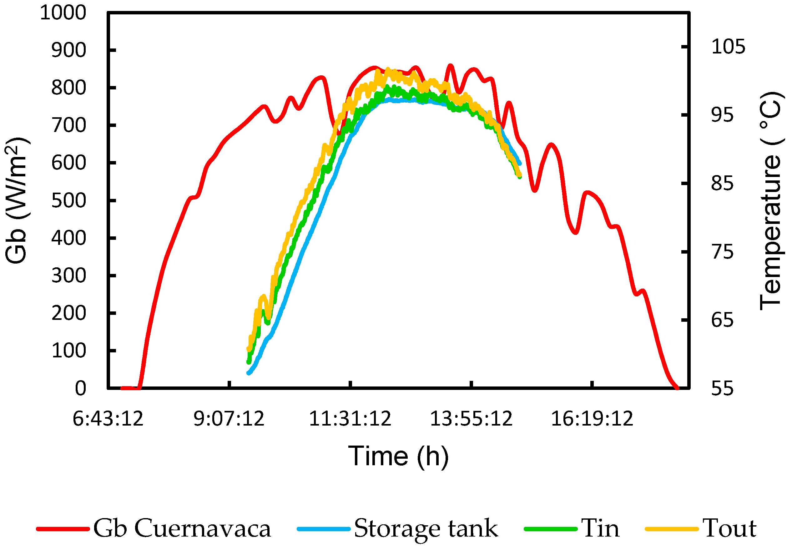
Figure 4 shows the temperature profiles of the storage tank, inlet, and outlet temperature as a function of solar irradiance (
Gb) corresponding to November 24. The test was considered for an office schedule from 10:00 a.m. to 16:00 p.m., the solar radiation showed a Gaussian profile, this day the maximum
Gb was 856 W/m
2 in Cuernavaca city. In the storage tank profile, it is possible to identify three sections: the transitory section from 9:30 a.m. to 12:00 p.m., the stable section from 12:00 p.m. to 14:00 p.m., and the cooling section from 14:00 p.m. to 16:00 p.m. The temperature profiles increased as the solar irradiance increased, however, the
Gb decreased after the 12:00 p.m. The behavior of the storage tank temperature profile was kept constant for two hours. The average temperature held in the storage tank was 97.2 °C, the maximum outlet temperature HTF was 103.3 °C.
The thermal efficiency and the useful heat were calculated during the stable section, these behaviors were shown in
Figure 5. This plot shows the behavior of several parameters every 10 min. The maximum value calculated for thermal efficiency was 19.8% and the minimum 9.8%. The useful heat was determined considering 38.43 m
2 as the total collector’s area and
Gb in a range from 759 to 854 W/m
2. The results show the useful heat can reach 6.5 kW as maximum and 3 kW as a minimum. The behavior of Qu is not constant due to the
Gb variation during the test. The exergy efficiency follows the same trend than others parameters varying from 7 to 14.2%.
The test of corresponding of 29 November is presented in
Figure 6. It shows the profiles of inlet, outlet, and storage tank temperatures during the day in Cuernavaca city. The solar radiation showed a Gaussian profile, the maximum
Gb was 835 W/m
2, after the 12:10 p.m. a few clouds showed up. The temperature profiles for the variables Tin and Tout, diminished when the clouds appeared. The evaluation was realized for 6 h (9:30 a.m.–15:30 p.m.). In this plot is possible to identify three sections also, the stable section was in a range from 11:39 a.m. to 14:39 p.m. During this section, the average storage tank temperature was 96.93 °C and the maximum outlet temperature of HTF was 102.72 °C.
The analysis of thermal efficiency and useful heat is presented in
Figure 7. It shows the behavior of thermal efficiency for the stable section, for which the maximum value calculated was 16.95%, this value is the average efficiency for a 10 min period. The useful heat behavior varied from 2.9 kW to 5.2 kW, the
Gb was registered between 700.1 W/m
2 to 832 W/m
2. In this case, the exergy efficiency varied between 7.4 and 11.7.
Figure 8 shows the temperature profiles in the storage tank, and at the inlet and outlet from the solar collector’s field as a function of the solar irradiance (Gb) registered in Cuernavaca in 5 December. The solar radiation presents a normal profile; however, some clouds appeared during the day as it can be seen in the plot, the maximum
Gb was 859 W/m
2. The period of evaluation was considered from 9:30 a.m. to 15:00 p.m. For this day the stable section was in a range from 12:00 p.m. to 14:00 p.m. The behavior of the storage tank temperature profile was held constant for two hours. The average temperature held in the storage tank was 96.8 °C, the maximum outlet temperature HTF was 101.7 °C.
The thermal efficiency and useful heat were analyzed for the stable section and are presented in
Figure 9. In this day the values of efficiency were lower than other tests, the
Gb was registered in a range from 668.6 to 853 W/m
2, as a result of a cloudy day, the maximum value calculated was 14.82% and the minimum was 6.27%. The data was average of efficiency every 10 min. However, the useful heat was between 1.9 to 4.9 kW when the
Gb was around 853 W/m
2. The minimum exergy efficiency was around 4.2 at 14:00 while the maximum value was 11.1 at 12:09.
The
Figure 10, corresponding to 11 December, shows the solar radiation behavior and the temperature profiles for the inlet, outlet, and storage tank during the day. The Gaussian profile presents a maximum
Gb was 987 W/m
2 in Cuernavaca city, this value is the highest value registered with respect to the reported previously. The evaluation was carried out for 5.5 h (9:30 a.m.–15:00 p.m.). In the stable section was presented between 12:17 p.m. to 14:45 p.m. It is very interesting the behavior of the storage tank temperature, because it was kept constant during 5.5 h. The average storage tank temperature was 96.0 °C and the maximum outlet temperature of HTF was 102.6 °C.
The analysis of thermal efficiency and useful heat are presented in
Figure 11. It shows the behavior of thermal efficiency for the stable section (9:30 a.m.–15:00 p.m.), for which the maximum value calculated was 15.80% and the minimum was 8.05%. The useful heat behavior varied in a range from 2.95 kW to 5.98 kW, the
Gb was registered between 981 W/m
2 and 954 W/m
2. The decreasing trend in the useful energy is associated with the proximity of this temperature to the boiling temperature in the city of Cuernavaca. The exergy efficiency follows the same trend than others parameters, varying from 7.8 to 15%.
According to the results of the evaluation of solar collectors, the outlet temperature data was used as inlet data of absorption cycle, the inlet temperature was in a range from 85 to 95 °C, according to the results of PTCs. The useful heat was considered to be supplied to the generator in a range from 1.9 to 6.5 kW.
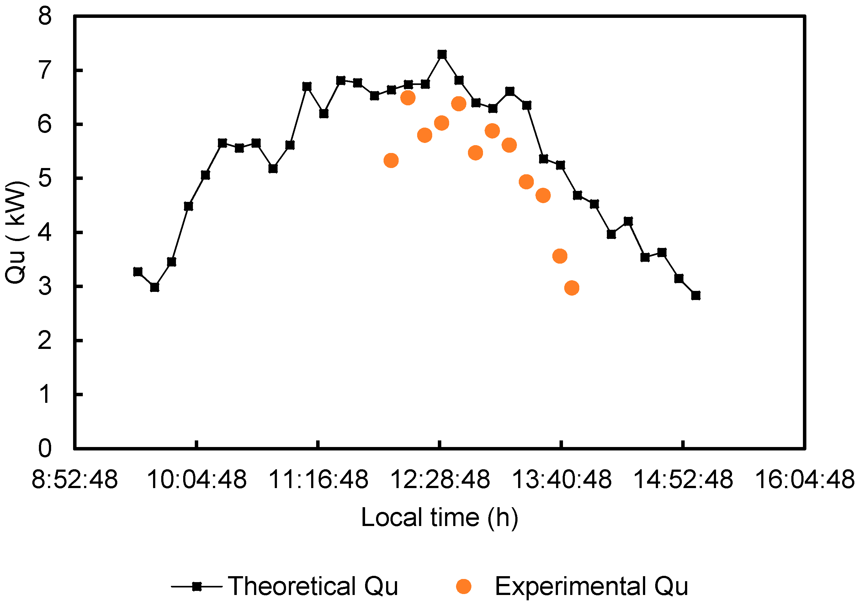
In
Figure 12, a comparison of the theoretical and experimental useful heat for the collectors’ field is presented for one typical day. The figure shows a variation of Qu as a function of the test time. The theoretical maximum values were obtained at solar noon, when the value of the angle of incidence is zero. In
Figure 12, the useful heat flux is affected by the global thermal losses estimated as (
UL’) × (
Ar) = 13.67 W/K. However, the negative trend for larger values of the angle of incidence is caused by the incidence angle modifier described by the Equation (3).
Figure 13,
Figure 14,
Figure 15 and
Figure 16 show the experimental evaluation of absorption cooling system taking into account the previous results.
Figure 13 shows the external generation power as a function of the heating water temperature, for several condensation water temperatures. In the presented curves it is possible to identify two sections: in the first one, the thermal power increases linearly with the increases in the heating water temperature, this behavior is kept to a point where there is no increase in the thermal power, this point gives rise to the second section of the curves, in which the thermal power does not tend to present any change when the generation temperature is increased.
The generation temperatures in the initial zone of each curve represent the temperatures of the heating water to which the absorption refrigeration system can begin to operate, however, in this section, there is still potential for heat transfer to the solution, so the operation of the cooling system is recommended at a temperature outside this zone. The fact of operating the absorption system at a generation temperature where the slope of each curve changes, guarantees that the potential for the heat transfer (temperature difference) in the generator has been used effectively. Finally, in the second operation zone, it is observed that when the temperature of the generation water is increased, there is no increase in the thermal power transmitted to the solution.
As it can be seen in
Figure 13, for the curves corresponding to a condensation water temperature at 26 °C and 28 °C, the condition in which the cooling power reaches its maximum is not perceived. This is due, because, for these curves, this point is above the range of generation temperatures considered.
Figure 13 is very important to determine at what temperature the hot water is expected to be supplied to the system generator, in order to get an acceptable performance from the absorption cooling system, this temperature depends on the available condensation water temperature.
In
Figure 14, the external generation power is plotted as a function of the external cooling power. In this figure, it can be seen that for each condensation temperature shown, there is an approximately linear relationship between these variables. This figure shows that, for the range of operating conditions shown (condensation water temperature), a linear function can be found that relates the required generation power to the desired cooling power.
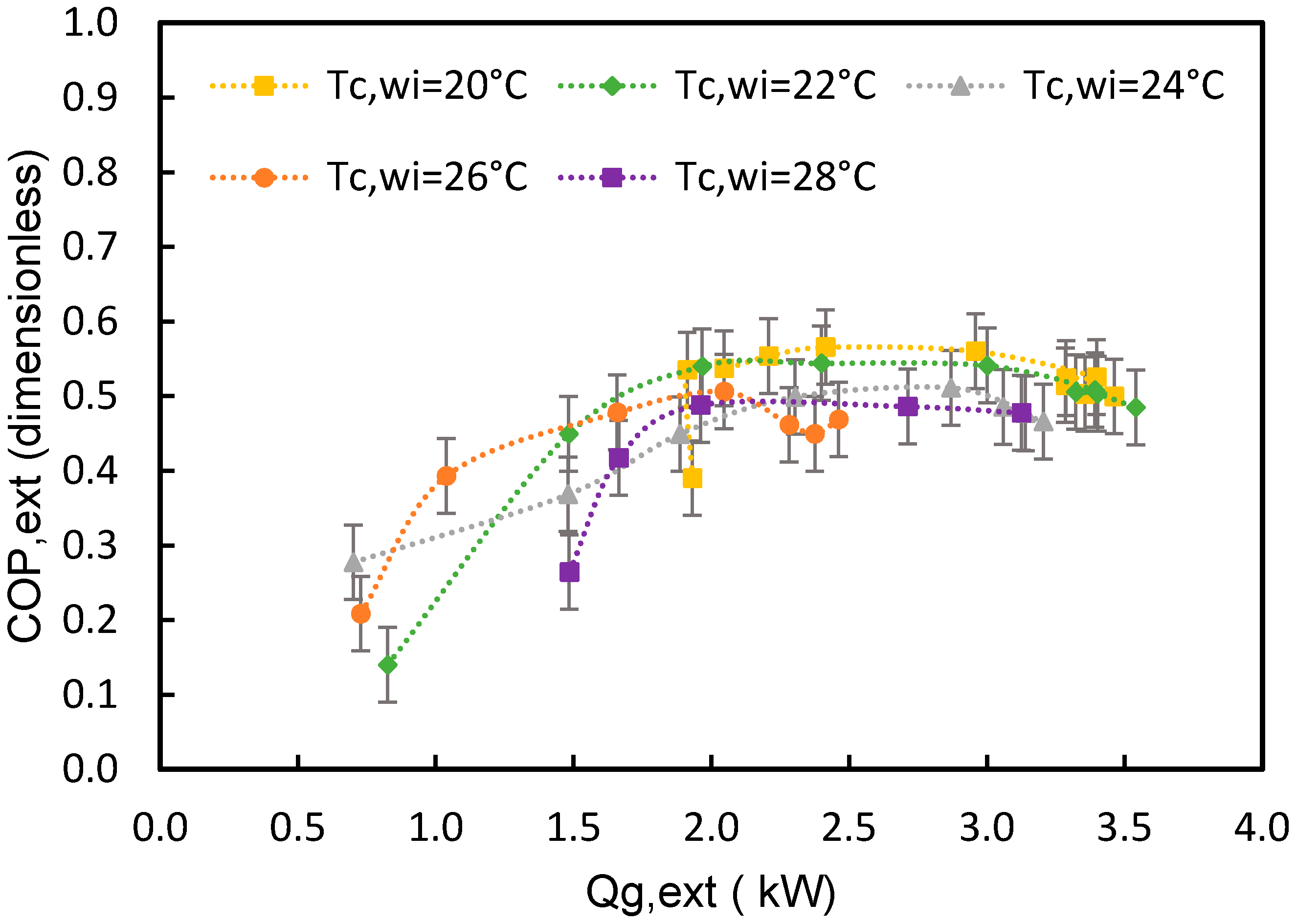
Figure 15 shows the variation of the external coefficient of performance as a function of the external heating power, for each condensation temperature. From this figure it is observed that for each curve, as the heating power increases, the COP initially presents an increasing trend, after that, it reaches a maximum point and subsequently decreases with the increase in the heating power. It is worth mentioning that since during the tests reported, the solution mass flow rate was maintained constant through the system generator, so the increase in thermal power is due to an increase in the generation water temperature.
Figure 15 shows that, regarding the amount of heat supplied in the system generator, there is a limit that is not convenient to exceed since the performance of the absorption cooling system will be affected negatively, this is due to the fact that, experimentally in the generator, a thermal energy supply beyond the maximum point does not produce an equivalent cooling effect, so the coefficient of performance is reduced.
Finally,
Figure 16, shows the variation in internal and external coefficients of performance as well as the exergy efficiency for the absorption cooling system, as a consequence of the simultaneous variation in the temperatures of the heating water and the water to be chilled in the evaporator. It is observed that during the experimental test, the internal coefficient of performance showed a slightly increasing trend, which is due to the effect of increasing the temperature of the heating water. On the other hand, the curve corresponding to the external COP shows a downward trend, which indicates that this parameter is more sensitive to the changes in the temperature of the water to be chilled than to the changes in the heating water temperature. The exergy efficiency was calculated using exclusively external parameters.
Figure 16 demonstrates that the highest exergy efficiency is obtained when the heating water temperature is minimum, in spite of the temperature of the water to be chilled, this fact would suggest that the higher generation temperatures the higher exergy destruction is obtained.
In
Table 5, the values for the solar coefficient of performance as well as the exergy efficiency at a condensation water temperature of 20 °C are presented.
On the other hand, the mean daily efficiency and cooling production that would be achieved with the combined system, is presented in
Table 6. These values were calculated taking into account the solar irradiance gained during the tests presented in this section, as well as the period of time during which the heating fluid temperature in the tank was constant. Moreover, it was considered that the temperature registered in the storage tank was the fluid temperature at the inlet port of the generator. This consideration implies that there is not any heat transfer from the fluid to the surroundings in the connection pipeline from the storage tank to the absorption cooling system, it could be a reasonable consideration if the pipeline is thermally insulated. The values in this table correspond to a condensation water temperature of 20 °C.


 and
and 


