Step-Climbing Tactics Using a Mobile Robot Pushing a Hand Cart


Abstract
1. Introduction
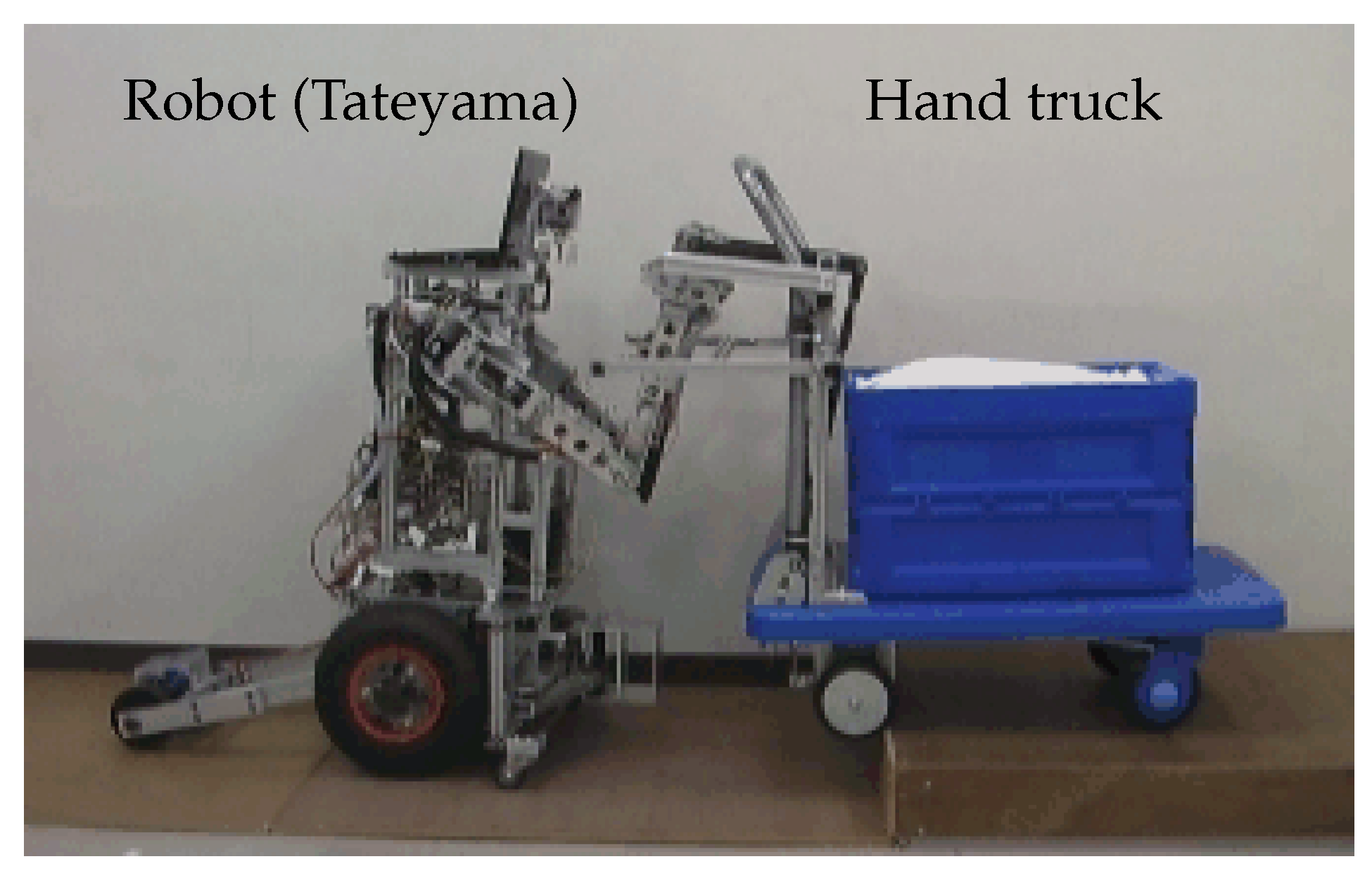
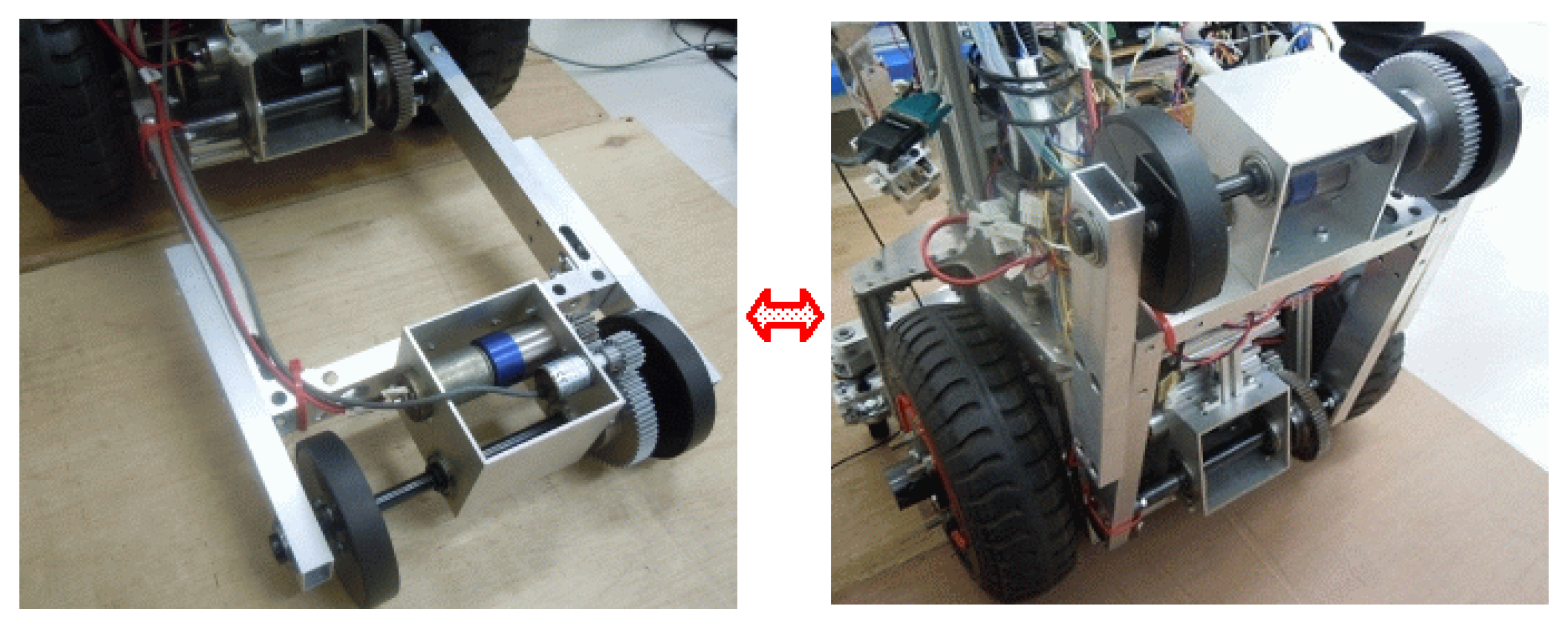
2. Hand Cart and Robot
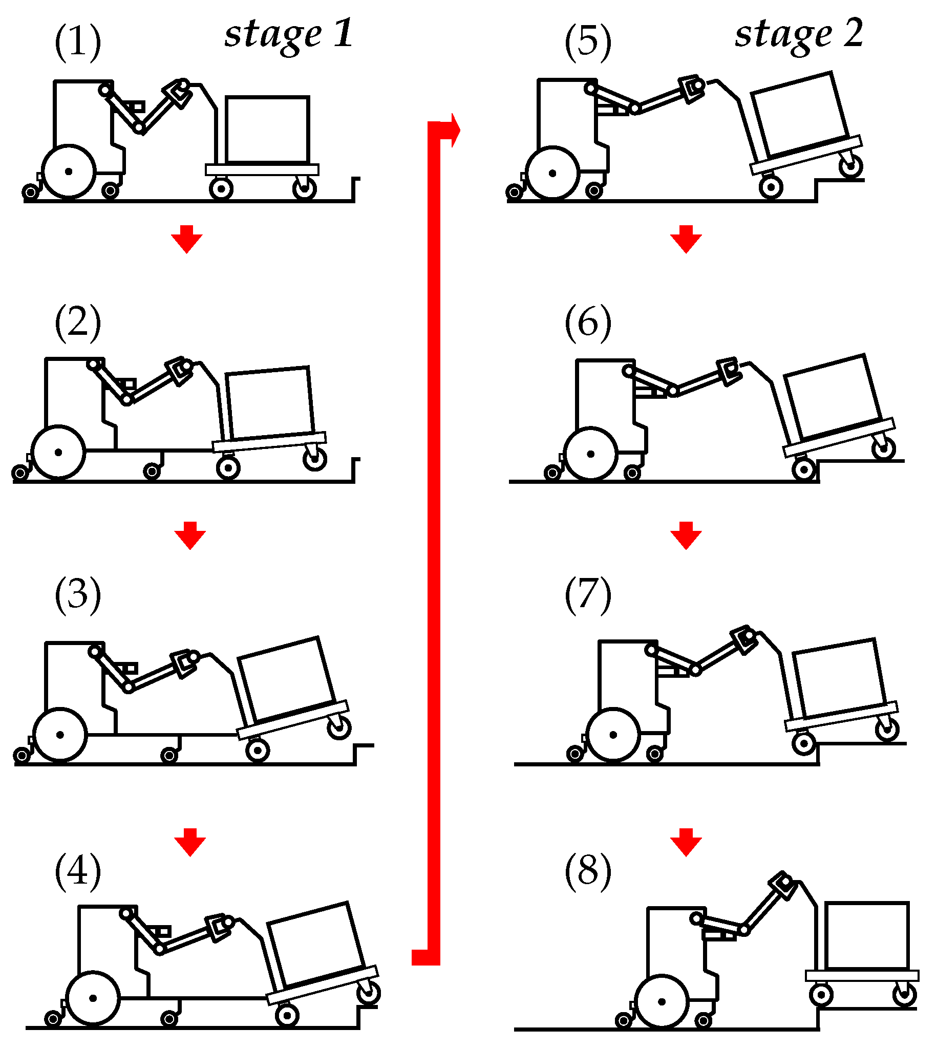
3. Process of Step Climbing
- (1)
- (2)
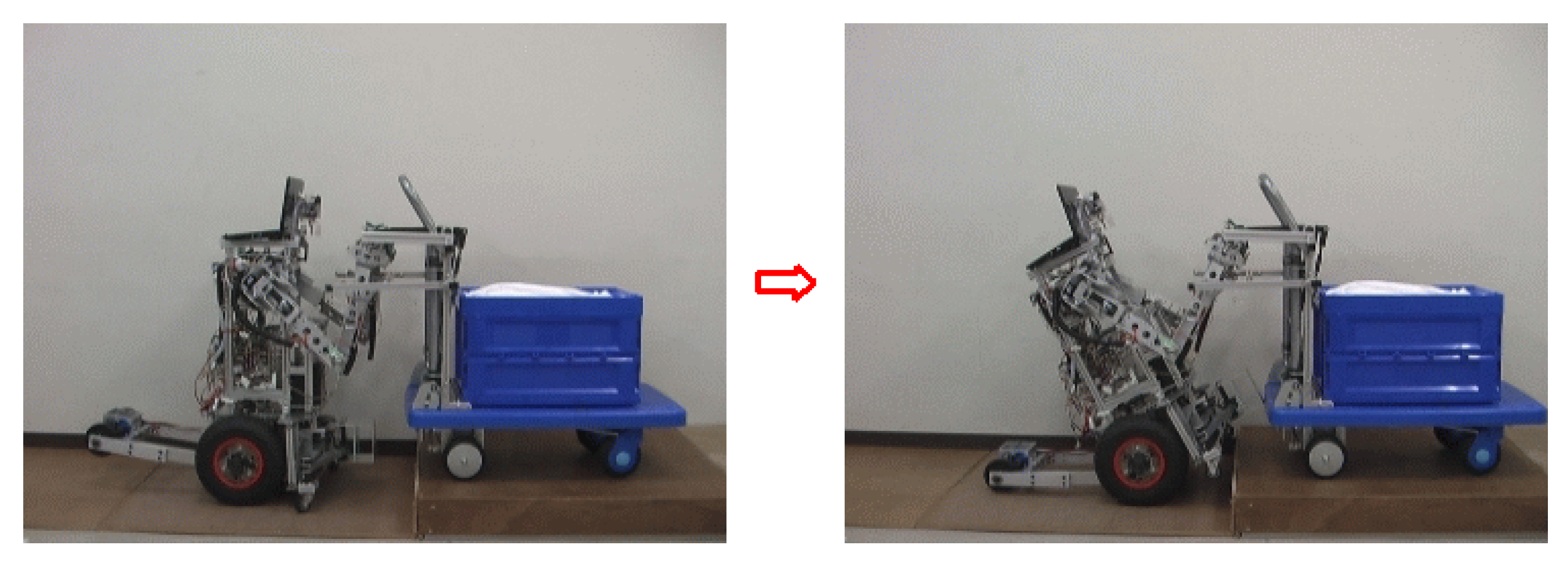
- The robot stops and pushes against the rear bottom part of the cart using the robot front-wheel mechanism (Figure 6). The front wheels of the cart start to be lifted.
- (3)
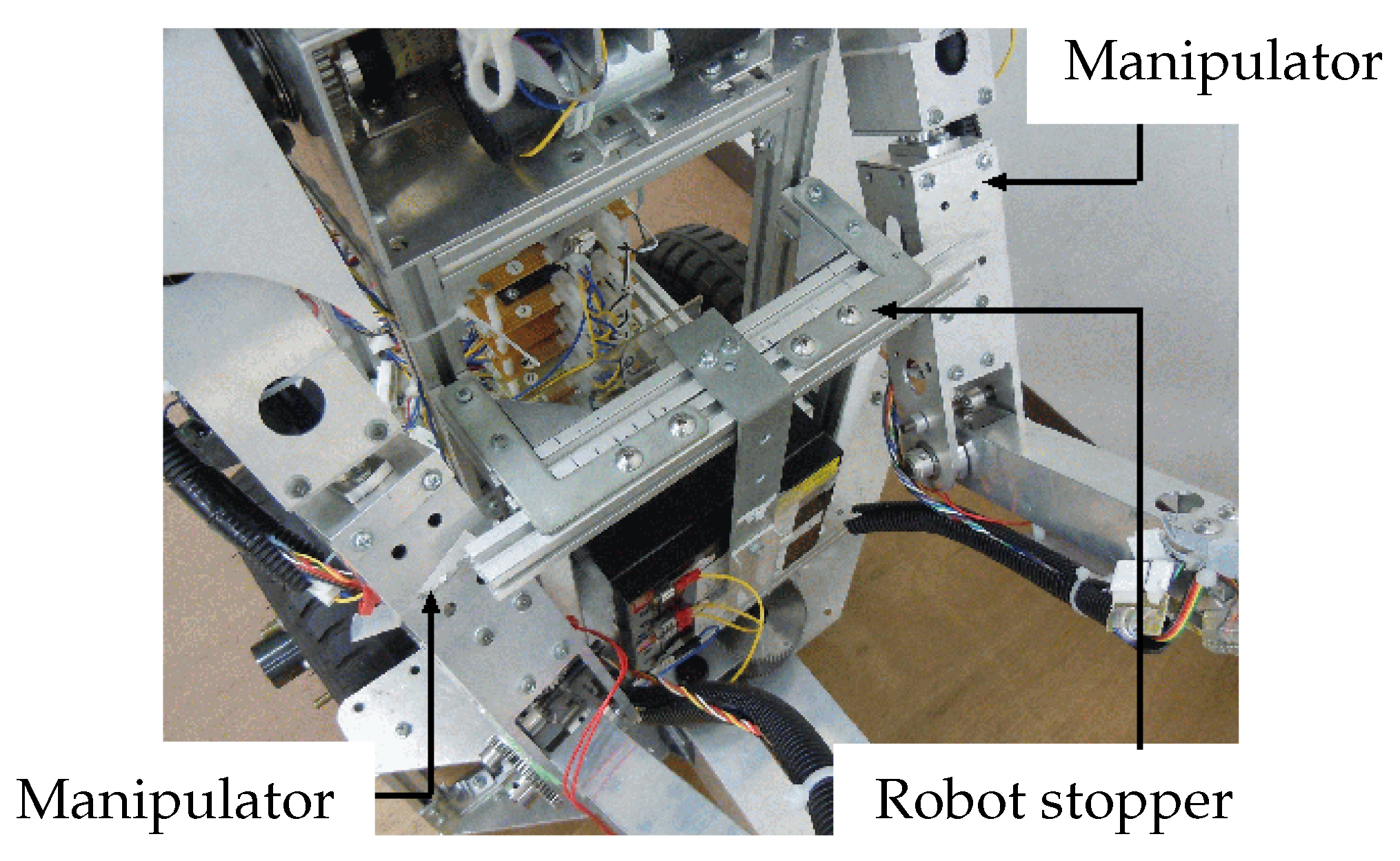
- The robot continues to push the rear bottom part of the cart, and the cart tilt increases. The action for lifting the front wheels of the cart exerts forces on the manipulators, causing passive rotation about Joint 2. However, the upper arm link of the manipulator comes into contact with the robot stopper, limiting the extent of rotation (Figure 9).
- (4)
- The robot moves forward and the front wheels of the cart are positioned over the edge of the step. As the operator closes the robot front-wheel mechanism, the incline of the cart becomes small. The front wheels of the cart are located on the upper level of the step.
- (5)
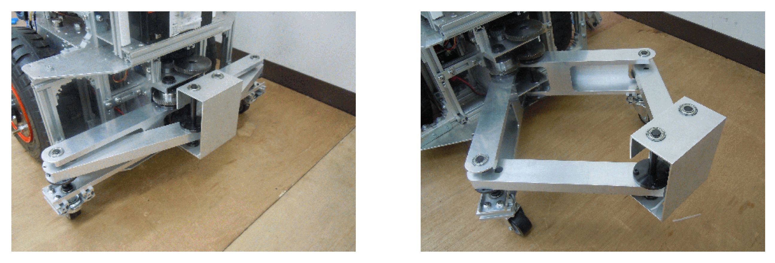
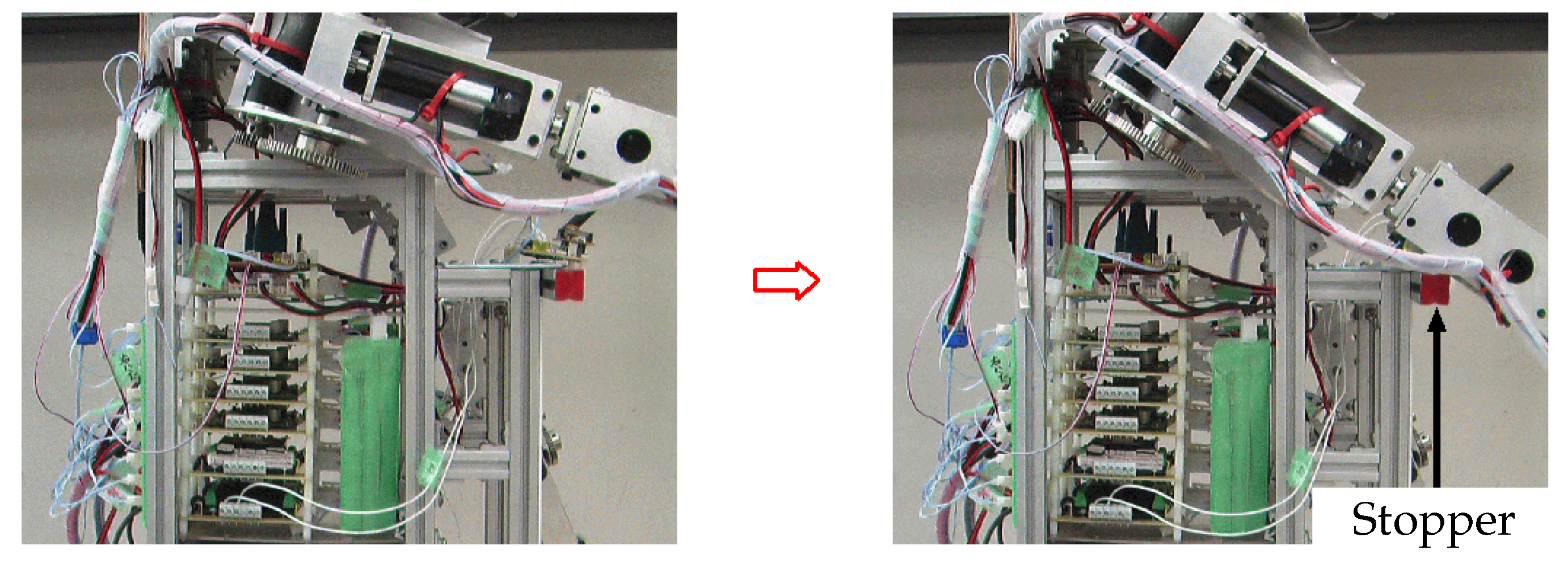
- First, the sides of the robot manipulators are opened, and the upper links of the manipulators are located in front of the robot stopper (Figure 10). This limits the passive rotational travel of the manipulators when the robot is pushed. The robot then moves forward, pushing the cart from behind.
- (6)
- The rear wheels of the cart come into contact with the step.
- (7)
- The robot pushes the cart, and the rear wheels of the cart begin to climb the step. The robot imitates the operation of a human pushing an heavy object by limiting the passive rotation about the shoulder joints as the upper arms are pushed into the chest (Figure 4).
- (8)
- Once the rear wheels of the cart have reached the upper level of the step, the robot stops.
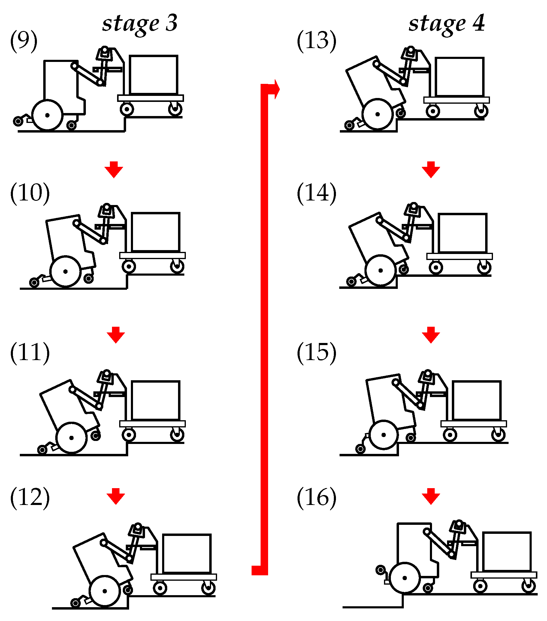
- (9)
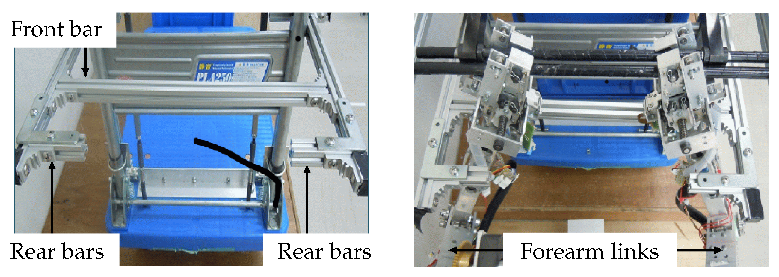
- The sides of the robot are opened, and the two manipulators are inserted into the stopper of the cart (Figure 12). The rear wheels of the robot are folded upward (Figure 13). The robot moves forward and the manipulator forearm links come into contact with the stopper of the cart. The hand brake is applied. The cart maintains its position (Figure 11).
- (10)
- The robot continues to push on the cart, and the front wheels of the robot are lifted (Figure 13).
- (11)
- When the location of the robot center of mass shifts behind the contact point between the robot middle wheels and the ground as the robot tilt increases, the robot begins to tip over backward. However, the robot is supported by the middle and rear wheels, and the rotational travel of the manipulators are stopped by the rear bars of cart’s stopper. The brake of cart is then released (Figure 11).
- (12)
- The robot moves forward using the middle and rear wheels, and the front wheels of the robot are placed on the upper level of the step.
- (13)
- The robot drives and both vehicles move forward.
- (14)
- The middle wheels of the robot come into contact with the step.
- (15)
- The middle wheels of the robot continue to drive, and both vehicles continue to move forward. The rear-wheel mechanism of the robot is lowered and pushes up the robot body. The middle wheels of the robot start to climb the step.
- (16)
- The middle wheels of the robot are able to climb the step. After the middle wheels of the robot have reached the upper level of the step, the vehicles are stopped. The rear-wheel mechanism of the robot is then folded upward.
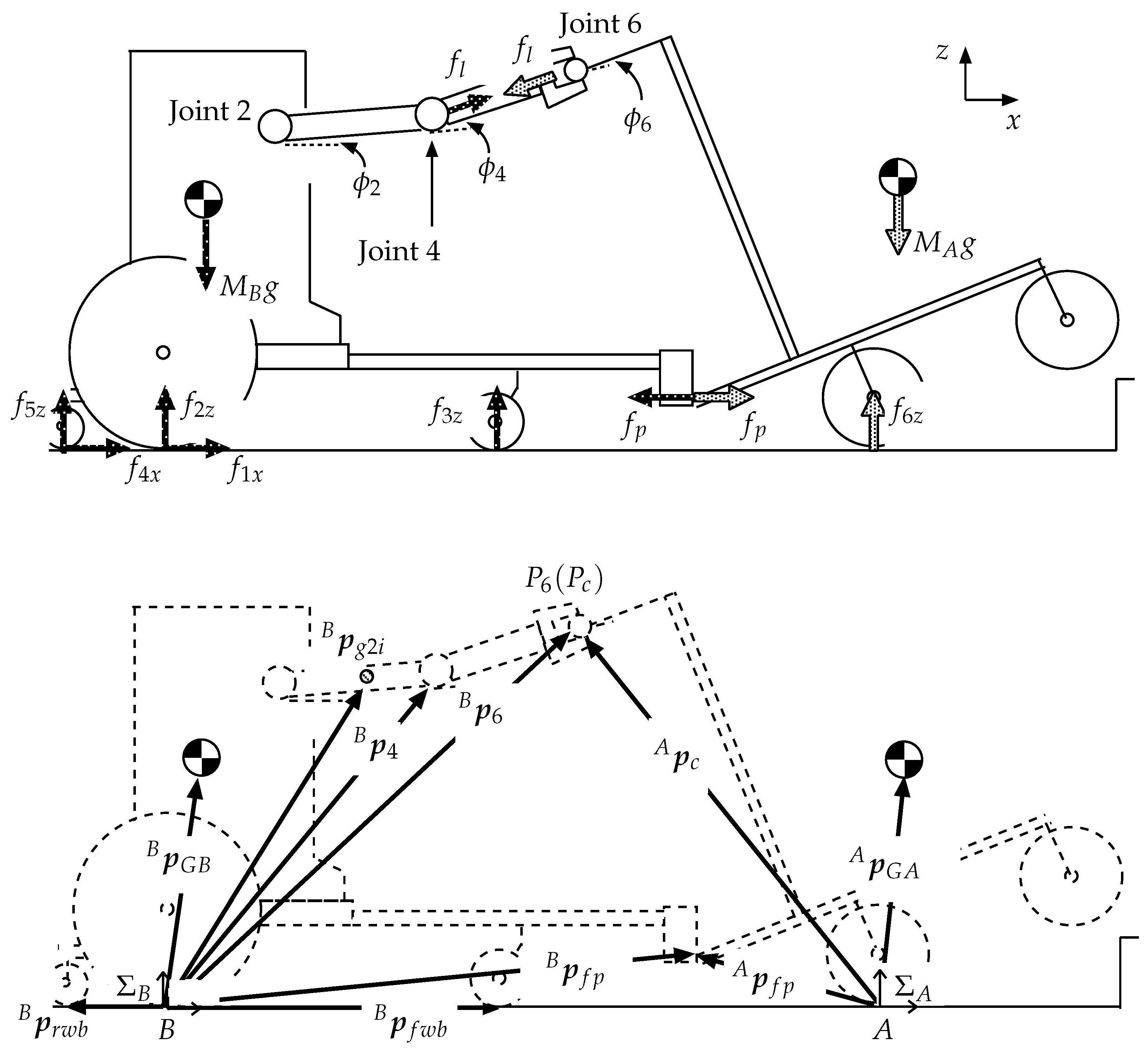
4. Theoretical Analysis
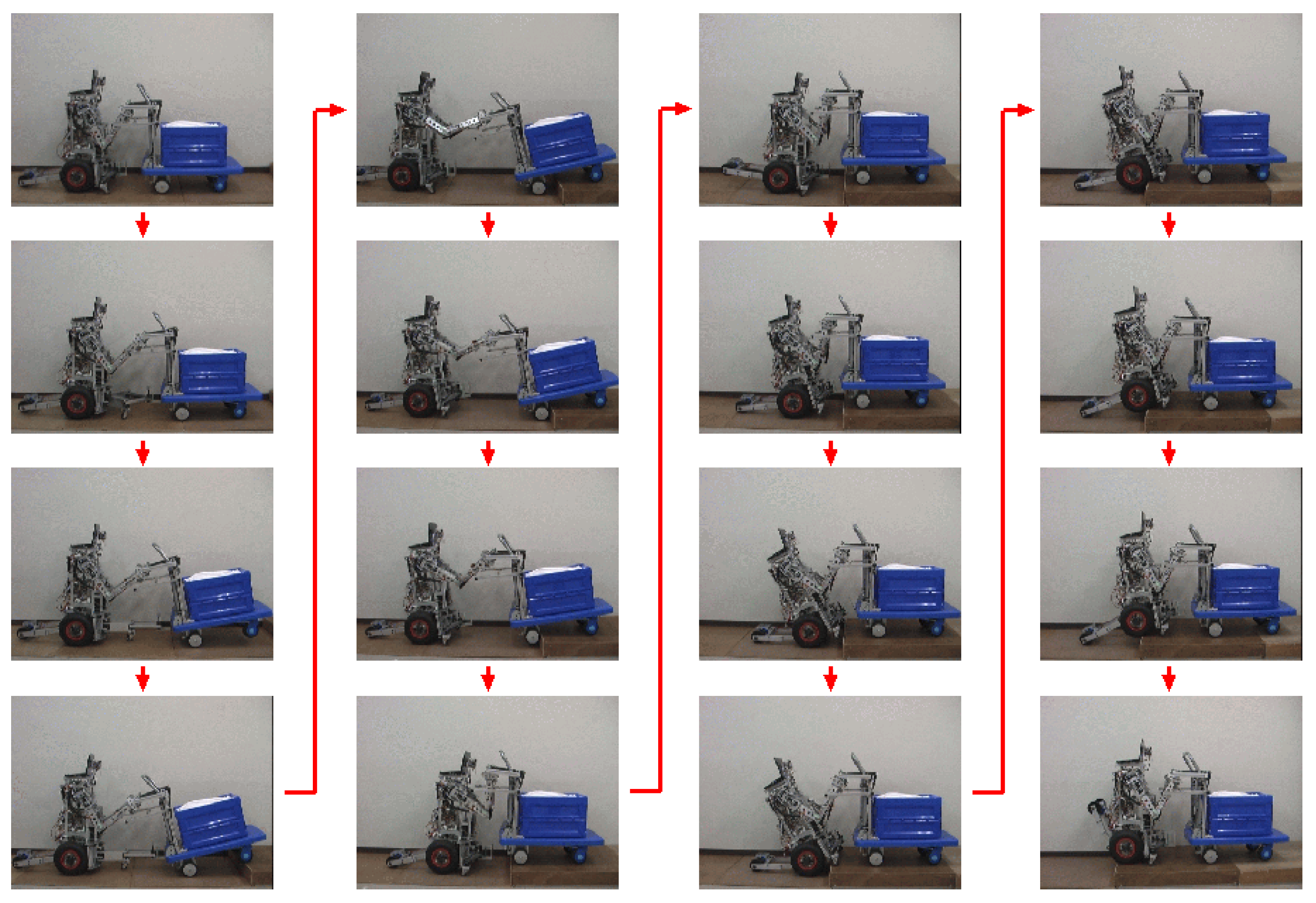
5. Experiment
6. Conclusions
- (1)
- The teleoperated robot and the hand cart are able to climb a step using the proposed method.
- (2)
- The operator requires some time (approximately 90 s) to change the position of the manipulators (after Stage 1). Both vehicles have individually driven wheels and are connected, and thus the trajectories of the vehicles are limited. Moreover, the teleoperated robot was controlled using a game pad, making operation of the robot difficult and indicating that system for changing the positions of the manipulators should be autonomous.
- (3)
- The camera on the robot cannot capture the entire situation of the vehicles. However, the additional camera on the robot chest was able to improve operability. The climbing task was also performed successfully by another operator.
Author Contributions
Funding
Acknowledgments
Conflicts of Interest
Appendix A

| Overall length | 230–800 mm |
| Overall height | 747 mm |
| Radius of front wheels () | 25 mm |
| Radius of center wheels () | 145 mm |
| Radius of rear wheels () | 19 mm |
| Length of the front-wheel mechanism () | 250–750 mm |
| Height of the front-wheel mechanism () | 250–70 mm (when the incline of the cart is 0) |
| Wheelbase | 190–440 mm |
| Wheelbase | 270 mm |
| Mass position from the rear axis | 93 mm |
| Height of the mass from the rear axis | 286 mm |
| Position of Joint 2 from the rear axis | 90 mm |
| Height of Joint 2 from the rear axis | 532 mm |
| Mass of the robot’s body | 56.2 kg |
| Mass of Link 2 (from Joint 2 to Joint 4) | 2.55 × 2 kg |
| Mass of Link 4 (form Joint 4 to the human hand) | 0.8 × 2 kg |
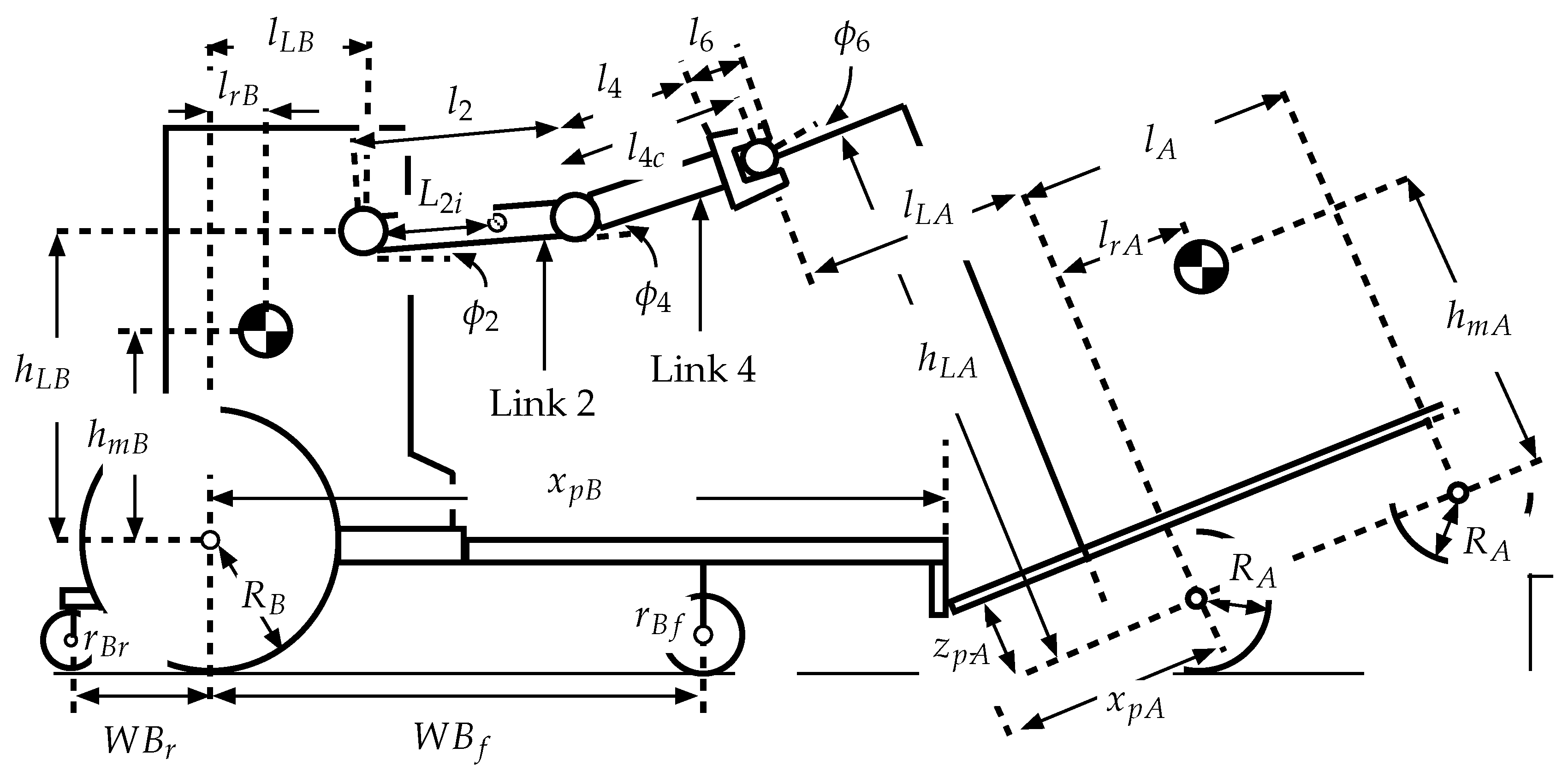
| Length of Link 2 () | 330 mm |
| Length of Link 4 () | 300 mm |
| Length of the hand () | 105 mm |
| Length from Joint 4 to the connecting position () | 370 mm |
| Mass position of Link 2 () | 67 mm |
| Mass position of Link 4 () | 169 mm |
| Mass position of Link 6 () | 35 mm |
| Overall length | 1020 mm |
| Overall height | 900 mm |
| Radius of the front and rear wheels () | 65 mm |
| Wheelbase () | 470 mm |
| Connecting height () | 695 mm |
| Connecting position () | 270 mm |
| Stopper position (front bar) from the axis of the rear wheels | 210 mm |
| Stopper position (rear bars) from the axis of the rear wheels | 360 mm |
| Stopper Height from the axis of the rear wheels | 500 mm |
| Length of contact position () | 160 mm |
| Height of contact position () | 150 mm |
| Mass position () | 235 mm |
| Mass height () | 350 mm |
| Mass () | 75 kg |
References
- Onozato, T.; Tamura, H.; Kambayashi, Y.; Katayama, S. A Control System for the Robot Shopping Cart. In Proceedings of the 2010 ERAST International Congress on Computer Applications and Computational Science, Singapore, 4–6 December 2010; pp. 907–910. [Google Scholar]
- Sales, J.; Mart, J.V.; Marn, R.; Cervera, E.; Sanz, P.J. CompaRob: The Shopping Cart Assistance Robot. Int. J. Distrib. Sens. Netw. 2015, 1–15. [Google Scholar] [CrossRef]
- Lee, H.; Lee, G.; Kwon, C.; Noguchi, N.; Chong, N.Y. Swithched Observer Based Impedance Control for an Assistive Robotic Cart unbder Unknown Parameters. In Proceedings of the IEEE RO-MAN: The 21st IEEE International Symposium on Robot and Human Interactive Communication, Paris, France, 9–13 September 2012; pp. 101–106. [Google Scholar]
- Takahashi, T.; Suzuki, T.; Shitamoto, H.; Moriguchi, M.; Yoshida, K. Developing a mobile robot for transport applications in the hospital domain. Robot. Auton. Syst. 2010, 58, 889–899. [Google Scholar] [CrossRef]
- Scholz, J.; Chitta, S.; Marthi, B.; Likhachev, M. Cart pushing with a mobile manipulation system: Towards navigation with moveable objects. In Proceedings of the 2011 IEEE International Conference on Robotics and Automation, Shanghai, China, 9–13 May 2011; pp. 6115–6120. [Google Scholar]
- Iwamura, Y.; Shiomi, M.; Kanda, T.; Ishiguro, H.; Hagita, N. Do elderly people prefer a conversational humanoid as a shopping assistant partner in supermarkets? In Proceedings of the 6th International Conference on Human-Robot Interaction, Lausanne, Switzerland, 6–9 March 2011; pp. 449–456. [Google Scholar]
- Ohno, N.; Hasegawa, T. Controller of Mobile Robot. U.S. Patent US8340823 B2, 25 December 2012. [Google Scholar]
- Nozawa, S.; Maki, T.; Kojima, M.; Kanzaki, S.; Okada, K.; Inaba, M. Wheelchair support by a humanoid through integrating environment recognition, whole-body control and human-interface behind the user. In Proceedings of the 2008 IEEE/RSJ International Conference on Intelligent Robots and Systems, Nice, France, 22–26 Septmber 2008; pp. 1558–1563. [Google Scholar]
- Nakajima, S.; Nakano, S.; Takahashi, T. Free gait algorithm with two returning legs of a leg-wheel robot. J. Robot. Mechatron. 2008, 20, 661–668. [Google Scholar] [CrossRef]
- Kumar, V.; Krovi, V. Optimal Traction Control In A Wheelchair With legs And Wheels. In Proceedings of the 4th National Applied Mechanisms and Robotics Conference, Cincinnati, OH, USA, 10–13 December 1995. [Google Scholar]
- Gonzalez, A.; Ottaviano, E.; Ceccarelli, M. On the Kinematic Functionality of s Four-bar Based Mechanism for Guiding Wheels in Climbing Steps and Obstacles. Mech. Mach. Theory 2009, 44, 1507–1523. [Google Scholar] [CrossRef]
- Independence Technology, L.L.C., iBOT. Available online: http://www.hizook.com/blog/2009/02/11/ibot-discontinued-unfortunate-disabled-perhaps-budding-robotics-opportunity (accessed on 11 February 2009).
- Asama, H.; Sato, M.; Goto, N.; Kaetsu, H.; Matsumoto, A.; Endo, I. Mutual transportation of cooperative mobile robots using forklift mechanisms. In Proceedings of the 1996 IEEE International Conference on Robotics and Automation, Minneapolis, MN, USA, 22–28 April 1996. [Google Scholar]
- Ikeda, H. Step climbing strategy for a wheelchair. In Advances in Intelligent Systems: Reviews; Reviews Book Series; Yurish, S., Ed.; IFSA Publishing, S.L.: Barcelona, Spain, 2017; Volume 1, Chapter 10; pp. 249–288. [Google Scholar]
- Ikeda, H.; Hashimoto, K.; Murayama, D.; Yamazaki, R.; Nakano, E. Collision avoidance between a wheelchair front wheels and a step wall during step climbing using a care robot. Adv. Sci. Technol. Eng. Syst. J. 2017, 2, 732–740. [Google Scholar] [CrossRef]
- Ikeda, H. Establishment of step climbing technology for a heavy carrier using a robot which is driven by low power motors. Rep. Matsuda Found. 2014, 26, 87–94. (In Japanese) [Google Scholar]


© 2018 by the authors. Licensee MDPI, Basel, Switzerland. This article is an open access article distributed under the terms and conditions of the Creative Commons Attribution (CC BY) license (http://creativecommons.org/licenses/by/4.0/).
Share and Cite
Ikeda, H.; Kawabe, T.; Wada, R.; Sato, K. Step-Climbing Tactics Using a Mobile Robot Pushing a Hand Cart. Appl. Sci. 2018, 8, 2114. https://doi.org/10.3390/app8112114
Ikeda H, Kawabe T, Wada R, Sato K. Step-Climbing Tactics Using a Mobile Robot Pushing a Hand Cart. Applied Sciences. 2018; 8(11):2114. https://doi.org/10.3390/app8112114
Chicago/Turabian StyleIkeda, Hidetoshi, Takuya Kawabe, Ryousuke Wada, and Keisuke Sato. 2018. "Step-Climbing Tactics Using a Mobile Robot Pushing a Hand Cart" Applied Sciences 8, no. 11: 2114. https://doi.org/10.3390/app8112114
APA StyleIkeda, H., Kawabe, T., Wada, R., & Sato, K. (2018). Step-Climbing Tactics Using a Mobile Robot Pushing a Hand Cart. Applied Sciences, 8(11), 2114. https://doi.org/10.3390/app8112114