Article

Analysis of the Fatigue Crack Propagation Process of the Stress-Absorption Layer of Composite Pavement Based on Reliability

1
School of Transportation Engineering, Shenyang Jianzhu University, Shenyang 110168, China
2
Cscec Science & Technology Changchun Co., Ltd., Changchun 130000, China
3
Institute of Transportation Engineering, Zhejiang University, Hangzhou 310058, China
4
School of Science, Shenyang Jianzhu University, Shenyang 110168, China
*
Authors to whom correspondence should be addressed.
Appl. Sci. 2018, 8(11), 2093; https://doi.org/10.3390/app8112093
Submission received: 25 August 2018 / Revised: 23 October 2018 / Accepted: 25 October 2018 / Published: 30 October 2018

Abstract

:
The stress-absorption layer in cement concrete pavement delays the development of reflection cracks and is good at fatigue resistance. Laboratory investigations of the anti-crack performance of the high viscous asphalt sand stress-absorption layer (HVASAL) and rubber asphalt stress-absorption layer (RASAL) were carried out by force-controlled fatigue crack propagation tests, for which three types of overlay structures with three types of pre-crack (i.e., the middle crack, the side crack, and the 45° inclined crack) were designed. A probability model was established to describe the propagation of the fatigue cracks. The fatigue crack propagation, the fatigue life, the crack propagation rate, and the crack propagation mechanism of the three types of overlay structure were compared and analyzed. The results show that the stress-absorption layers have good anti-crack fatigue performance, and that the RASAL is better than the HVASAL. The crack propagation patterns of the three types of overlay structure were found. In the double logarithmic coordinate, the curves of the three types of cracks are straight lines with different intercepts and slopes. The probability model quantifies the relationship between the crack propagation rate and ∆K. The influences of the three types of crack on the fatigue properties of the asphalt overlays are different.

1. Introduction

Nowadays, adding a paving asphalt layer on cracked cement concrete pavement is a widespread construction measure. Due to defects in the cement concrete layer, the bearing capacity of the structure decreases over time. As the pavement temperature increases, the effects of the interface bonding on the overlay response amplify [1], and reflection cracks are more prone to occur in the overlay subjected to temperature change and loading; however, study has shown that glass fiber reinforced modified asphalt could strengthen the bonding and mitigate cracking of the overlay [2]. In order to delay the development of reflection cracks, the stress-absorption layer has been adopted domestically, and some experiments have been carried out to validate the effects of anti-crack performance. The stress-absorption layer, set between the cement concrete layer and the asphalt layer, can delay the occurrence of a reflection crack, because the deformation and the ability of elastic recovery of the layer reduces the stress concentration [3]. The stress-absorption layer is good at fatigue resistance, because the layer dissipates the concentrated stress and prevents the emergence of fatigue cracks in it, and consequently, it slows down the speed of propagation of the reflection crack, and thus attains the objectives of preventing and controlling the cracks. Nowadays, the theories and methods of fatigue fracture mechanics have been used to study the cracks of asphalt pavement. The nonlinear X-SBFEM (which is the extended proportional boundary finite element method) is capable of modeling the nonlinear fracture propagation process while taking into account the effects of cohesive interactions [4], because the main reason for the failure of the asphalt pavement is fatigue failure under the persistent actions of traffic load and temperature load. Therefore, research of the fatigue crack propagation law of the asphalt pavement is important. The fatigue failure of asphalt pavement can be divided into two stages: The fatigue-initiation stage and the fatigue fracture stage. Some experience has been accumulated in the study of the fatigue initiation stage, and the results have been used so far. The study of the fatigue fracture stage showed that the fractured area increased significantly as the interface bonding strength decreased. On the contrary, the fractured area decreased slightly as the interface stiffness decreased [5].
In the past, model I cracks were researched mainly through fatigue fracture tests for asphalt-overlay composite pavement. In fact, I-II composite cracks have existed extensively in pavement structures, but few experiments have been conducted [6,7,8,9,10,11]. The propagation behavior of composite cracks was previously simulated through the uniaxial compression experiment using a notched beam, but the cyclic loading was not applied, and the type of crack and the trend of the crack propagation were also lacking [12]. Test simulations of the propagation process of load reflective cracking and temperature reflective cracking have been carried out to evaluate the cracking resistance of the stress-absorption layer, and it has been proven that paving of the stress-absorption layer is a good method to delay reflection cracks; however, only the influence of loading and temperature on the stress-absorption layer was tested, the material of the stress-absorption layer and the crack were not included [13]. The effects of the thickness of the stress-absorption layer on the speed of the propagation of the reflection crack have also been investigated, but the mechanism of the stress-absorption layer was not quite clear [14,15,16,17]. With the increase of the thickness of the stress-absorption layer, the speed of the propagation of the reflection crack would decrease, but the flexural and tensile effects of the overlay would increase, and also the cost [18,19,20]. It has been verified by engineering that the optimal thickness of the interlayer is 20–40 mm [9,10,21]. Laboratory investigations of three types of stress-absorption layer have been carried out by fatigue experiments. The results showed that the fatigue property of the rubber asphalt stress absorption layer (RASAL) was the best, and the service life of the pavement could be improved significantly by the material; however, the crack resistance of the stress-absorption layer is not very clear [22]. The abovementioned research shows that the stress absorption-layer is good at crack resistance. However, the analyses of the effects of the stress-absorption layer on the crack propagation process and the propagation trend of different crack types were not enough. It is important to study the influence of anti-crack additives, different crack modes, and test configurations on the crack propagation process and the propagation trend. Much research has been done on this. The mixed mode I/III fracture toughness of asphalt concrete materials was determined using the Edge Notched Disc Bend specimen [23]. Mixed mode I/II fracture toughness of five modified asphalt mixtures containing poly phosphoric acid (PPA), Styrene Butadiene Styrene (SBS), anti-stripping agent, crumb rubber (CR), and F-T paraffin wax (Sasobit), and an unmodified one (with no additive), were investigated experimentally using a large number of cracked semi-circular bend (SCB) specimens [24]. Two circular shape test specimens were designed and examined for the experimental determination of mode I fracture toughness in different modified hot mix asphalt materials [25]. The effects of carbon nanotubes as a binder modifier on the fatigue and fracture performance of asphalt mixtures were investigated [26]. Asphalt characteristic effects on its mixed mode I/II low temperature fracture toughness have also been investigated experimentally [27].
One study showed that for top-down cracking when the pavement was under repeated loading, shear damage occurred first in the asphalt layer, and then the damage extended horizontally, resulting in a shear-damaged layer. The damaged layer then led to a higher tensile strain in the upper mixture, which caused tension cracks, that finally propagated upwards to the pavement surface [28]. In this study, laboratory investigations of the anti-crack performance of the high viscous asphalt sand stress absorption layer (HVASAL) and the RASAL, and the propagation mechanism of different types of cracks, were carried out by force-controlled fatigue crack propagation tests, for which three types of overlay structure with three types of pre-crack were designed. The tests were conducted at room temperature and at the same loading rate, with the cyclic loading applied at the middle of the specimen. The three types of pre-crack were the middle crack, the side crack, and the 45° inclined crack. The fatigue crack propagation, fatigue life, crack propagation rate, and crack propagation mechanism of the three types of overlay structure were compared and analyzed. The crack propagation process of the three types of overlay with the same type of crack, and the three types of crack with the same type of overlay, were compared and analyzed as well. Considering the dispersion of the data of the crack propagations, a random probability model ( p d a d N Δ K model) based on the reliability theory was established to describe the propagation of the fatigue cracks. Using the least-square method, the relationships between the crack length a and the fatigue number N of the three types of crack were obtained by fitting the polynomials. The crack growth rates during the stable growth period of the three structures, and then the anti-crack performance of the structures, were compared. The curves of the three types of crack were analyzed. The variations of the intercept lg C and the slope n with the reliability p were discussed.

2. Materials and Methods

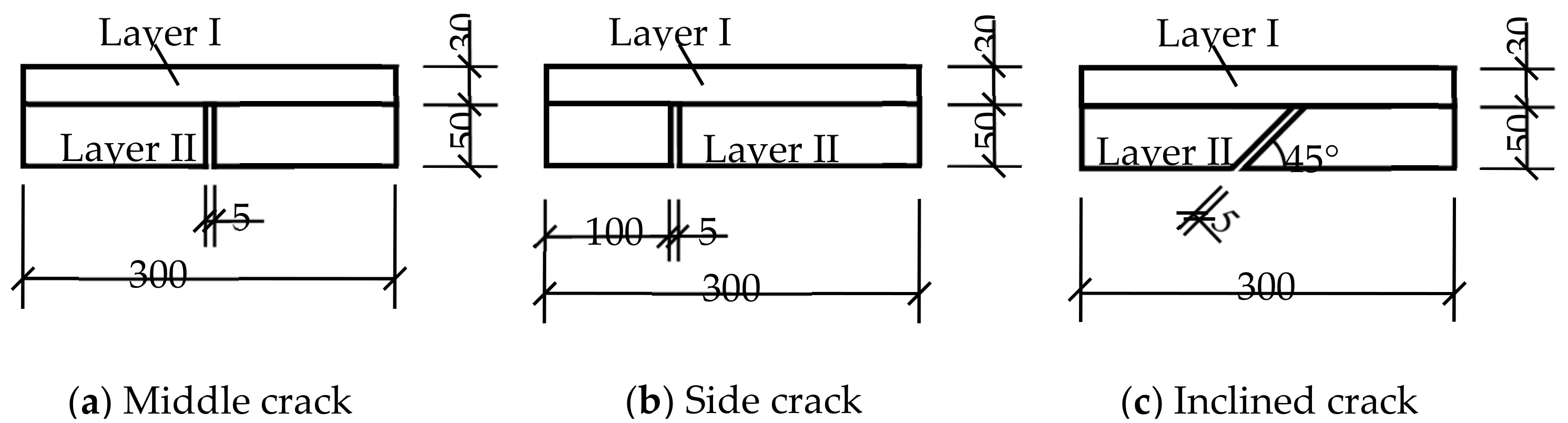
The size of the composite structure specimen was 300 × 90 × 100 mm3. The concrete composite had two or three layers: The No SAL type had a 50 mm AC-13 (a type of asphalt concrete) surface (layer I), and a 50 mm cement concrete layer (layer II); the HVASAL type had a 30 mm AC-13 surface (layer I), a 20 mm HVASAL (layer II), and a 50 mm cement concrete layer (layer III); the RASAL type had a 30 mm AC-13 surface (layer I), a 20 mm RASAL (layer II), and a 50 mm cement concrete layer (layer III). Three types of penetrating crack were designed (i.e., the middle crack, the side crack, and the 45° inclined crack), and the width of the cracks was 5 mm [29], as shown in Figure 1 and Figure 2.
A 70# asphalt (marking in accordance with the Chinese standard of the Technical Specifications for Construction of Highway Asphalt Pavements (JTG F40—2017) with a penetration of 70 was used as the asphalt binder for preparation of the specimens, and its specifications provided by the manufacturer are listed in Table 1. Limestone was used as the aggregate. The ratio of binder to aggregate was 8.1% by weight. The continuous aggregate gradation, having the nominal maximum size of 9.5 mm, is listed in Table 2. An additional 1% activated rubber crumb and 0.7% TCA additive (percentage of the mass of asphalt mixture) was added during the blending process.
(1)
To set the pre-crack, a board was placed in the test mold, and then the cement concrete was poured into the mold and flattened.
(2)
The mixed asphalt mixture was poured into the cement concrete rutting boards and compaction was performed.
(3)
The composite board was cut into specimens.
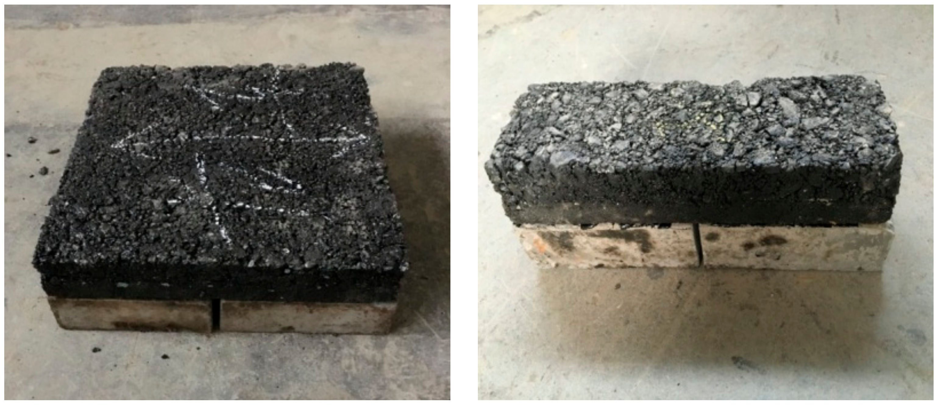
The prepared specimens with the middle crack are shown in Figure 3.
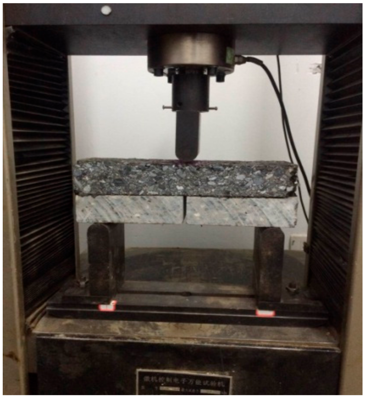
To accurately evaluate the crack resistance of HVASAL and RASAL, and investigate the propagation mechanism of the three types of crack, three-point bending failure tests and three-point bending fatigue performance tests were designed. Three-point bending failure tests were conducted to obtain the needed parameters for the three-point bending fatigue tests. Because of the thinness of the structure layer and the stress-absorption layer studied, the force control mode is closer to the actual stress state of the asphalt mixture in the pavement, so it can better explain the fatigue characteristics of the high viscosity asphalt [11]. Hence, the force-controlled loading mode was adopted for the three-point bending fatigue tests. For both the failure and the fatigue tests, the test temperature was set at 15 °C, the loading mode was the intermediate loading, the distance between the two ends was 250 mm, and the pressure head rate of the test machine was 2 mm/min, as shown in Figure 4. The ultimate load of the specimen was obtained by the three-point bending failure test. Forty percent of the ultimate load was used as the load for the three-point bending fatigue test.

3. Results

3.1. Test Results and Data Processing

To obtain the ultimate failure load and the load for the fatigue tests of the three types of crack, the failure experiments on the composite specimens without a stress-absorption layer were carried out at 15 °C. In order to reduce the test error, three identical specimens were used in each experiment configuration, and the average of the failure loads for the three specimens was taken as the final value, as listed in Table 3.
The test data was collected using a magnifying glass, the scale was marked across the overlay for easy observation, and the number of cycle loads corresponding to a crack propagation of 5 mm was used as the observation index [30]. The propagation of crack length corresponding to the load cycles was observed and recorded, as listed in Table 4.

3.2. Comparative Analysis of Anti-Crack Performance

To further investigate the anti-crack performance of the stress-absorption layers in the HVASAL and RASAL types, the crack propagation process of the three types of overlay with the same type of crack, and three types of crack with the same type of the overlay, were compared and analyzed.

3.2.1. Comparison and Analysis of the Crack Propagation Trends of the Three Types of Overlay with the Same Type of Crack

Two types of crack in the overlay of the specimen with the stress-absorption layer, propagated upwards across layers I and II. The data of the a-N curves with the stress-absorption overlay was graphed per each layer (a is the scale value of cracks in the overlay, and N is the corresponding number of load cycles). The a-N test curves of layer I and layer II for the three types of overlay with the middle crack are shown in Figure 5.
It was observed through the experiment that the initial cracking points for the middle cracks of the HVASAL and RASAL type structures were located at the interface between the stress-absorption layer and the surface layer. The cracks slowly propagated upwards, then some new cracks began to appear at the bottom of the stress-absorption layer, and the two cracks propagated upwards at the same time. The cracks in the two layers met as the length of crack in the stress-absorption layer reached 20 mm. It could be clearly observed that the cracks bypass the aggregate. As an example, the fatigue crack propagation process of the RASAL overlay structure is shown in Figure 6.
It was observed in the experiment with the No SAL type specimen with the middle crack, that the reflection cracks occurred along the interface of the cement concrete layer, as shown in Figure 7. The test results show that the number of load cycles for the initial-crack of the HVASAL and RASAL types is 2.34 and 3.25 times that of the No SAL type, respectively; and the fatigue life of the HVASAL and RASAL types is 1.79 and 2.01 times that of the No SAL type, respectively. The results show that the stress-absorption layer has the ability to retard the crack propagation, and the anti-crack performance of the RASAL type is better than that of the HVASAL type.
The a-N test curves of the three types of overlay structure in layers I and II with side cracks are shown in Figure 8.
It was observed that the experimental phenomena of the HVASAL and RASAL type overlay structures with side cracks were the same as those of the middle crack tests. However, the crack propagation direction was obviously deviated from the pressure head, and the propagation mode was open and shear composite. Furthermore, both mode cracks propagated at the same time, until the whole specimen was penetrated and broken. As an example, the fatigue crack propagation process of the HVASAL type overlay structure is shown in Figure 9.
It was observed that the initial cracking point of the side cracks of the No SAL type were located at the interface between the concrete layer and the surface layer, the crack propagation direction deviated from the pressure head, and the propagation mode was open and shear composite. Then the specimen produced small cracks at the bottom of the middle span which developed vertically, showing an open mode of crack propagation. The cracks of both modes began propagating at the same time, and the speed of the crack propagation of the former was faster than the latter in the initial stage. The latter propagated rapidly towards the top when the latter was longer than the former, and then the former no longer propagated, until the whole specimen was penetrated by the mid-span crack and broken. The crack propagation processes are shown in Figure 10. The test results show that the number of load cycles for initial-cracking of the HVASAL and RASAL types is 3.15 times and 4.05 times that of the No SAL type, respectively; and the fatigue life of the HVASAL and RASAL types is 1.61 times and 1.87 times that of the No SAL type, respectively. The results show that the stress-absorption layer has the ability to retard the crack propagation, and the anti-crack performance of the RASAL type is better than that of the HVASAL type.
The a-N test curves of the three types of overlay structure with the inclined crack were compared with that of layers I and II, as shown in Figure 11.
It was observed in the experiment that the pre-crack point of the inclined cracks of the No SAL type appeared directly under the pressure head. Then, on the upper right of the crack, and in the middle of the specimen, another crack appeared. The two cracks propagated upwards at the same time, they met, and became one crack propagating upwards until the cycles stopped. The pre-crack points of the inclined cracks of the HVASAL and RASAL types were located at the bottom of the surface layer, and there were soon many small cracks at the interface. The small cracks in the stress-absorption layer grew slowly, and when the cracks of the two layers were connected, the specimen was crushed and the cycles were stopped. The test results show that the number of load cycles for pre-crack of the HVASAL and RASAL types is 2.84 times and 3.27 times that of the No SAL type, respectively; and the fatigue life of the HVASAL and RASAL types is 1.55 times and 1.72 times that of the No SAL type, respectively. This shows that the stress-absorption layer has the ability to retard the crack propagation, and the anti-crack performance of the RASAL type is better than that of the HVASAL type.
The phenomenon of the pre-crack points always being located at the junction of two layers may be due to the difference of the elastic moduli and the poor bonding of the two layers. Therefore, we think that this is of great significance in road engineering. The bonding of the layers should be improved to decrease the rate of crack propagation and enhance the fatigue life of the pavement.

3.2.2. Analysis of the Crack Propagation Mechanism of Three Types of Crack with the Same Type of Overlay

The a-N curves of the crack propagation of the No SAL type structure with the three types of crack in layers I and II are shown in Figure 12.
For the No SAL type, the average fatigue numbers of the crack initiation of the middle crack, side crack, and inclined crack are 87 times, 63 times, and 102 times, respectively; and the average fatigue lives are 365 times, 308 times, and 469 times, respectively. The fatigue life of the side crack is shorter than the other two cracks, so the mode of open and shear composite crack caused by the side crack is more prone to fracture than the mode of a single open crack. Although the inclined crack is also the mode of open and shear composite, it has the longest fatigue life, and this can be attributed to the effect of partial healing of the cracks, and the propagation of the crack in the loading process is prevented.
The a-N curves of the crack propagation of the HVASAL type with the three types of crack in layers I and II are shown in Figure 13.
For the HVASAL type, in layer I, the average fatigue numbers of the crack initiation of the middle crack, side crack, and inclined crack are 204 times, 199 times, and 290 times, respectively; in layer II, the average fatigue numbers of crack initiation of the three types of crack are 237 times, 222 times, and 309 times, respectively; and the average fatigue lives are 653 times, 496 times, and 728 times, respectively. Compared with the No SAL type, the stress-absorption layer can absorb and disperse the stress, and increase the stress distribution area, so it greatly improves the anti-crack ability of the asphalt pavement surface under the fatigue load cycles.
The a-N curves of the crack propagation of three types of crack in layers I and II of the RASAL type are shown in Figure 14.
For the RASAL type, in layer I, the average fatigue numbers of the crack initiation of the middle crack, side crack, and inclined crack are 283 times, 255 times, and 334 times, respectively; in layer II, the average fatigue numbers are 316 times, 278 times, and 347 times, respectively; and the average fatigue life is 734 times, 509 times, and 809 times, respectively. What the three types of crack have in common is that the pre-crack points appear in layer I, and then cracks appear in layer II. The effect of cracks on the fatigue life of the RASAL type has the same trend as the No SAL and HVASAL types, but the RASAL type has a better anti-crack performance. It can be seen from the a-N curves of the three materials in Figure 12, Figure 13 and Figure 14 that different types of cracks (the middle crack, side crack, and inclined crack) in the cement concrete base have different effects on the fatigue properties of the overlay. As shown in Figure 12, Figure 13 and Figure 14, the inclined crack has the maximum fatigue life, the side crack has the minimum life, and the middle crack has an in-between life.

3.3. Analysis of Fatigue Fracture of Different Cracks Based on Reliability

Due to the effects of material properties, loading process, environmental factors, and crack propagation behaviors, the lives of the same specimens are uncertain. Take into account the effects and the dispersion of the fatigue crack propagation of different types of cracks; the p d a d N Δ K probability model to describe the fatigue crack propagation was established based on the original Paris formula [31,32] in this paper. The probability model can quantitatively relate the fatigue crack propagation rate and the impact of the types of crack to ∆K, and the change rules of parameters C and n.
Taking the logarithm on both sides of the Paris formula, we have
lg ( d a d N ) = lg C + n lg ( Δ K )  
The relation based on reliability p can be expressed as
lg ( d a d N ) = lg C P + n p lg ( Δ K )  
The distribution of fatigue crack propagation rate under the same stress intensity factor ∆K is logarithmic normal; that is, lg ( d a d N ) ~ N ( μ , σ 2 ) , and is defined as
lg ( d a d N ) P = μ + μ P σ  
p = Φ ( μ p ) = μ p 1 2 π e μ 2 2 d μ  
where μp is the standard normal deviation and can be found in the standard normal distribution table. In this paper, five reliability values were used as examples to study the variation of the parameters of the probability model for different fracture types. The test results are listed in Table 5, Table 6 and Table 7.
da/dN is determined by the method of increasing polynomial data from the a-N data measured in the experiment, and the approximate formula for calculating the range of the stress intensity factor ∆K is as follows:
Δ K = Δ P B W 2 + a W ( 1 a W ) 3 2 [ 0.886 + 4.64 a W 13.32 ( a W ) 2 + 14.72 ( a W ) 3 5.6 ( a W ) 4 ]  
where a is the length of the crack, B is the width of the specimen, and W is the width of the crack.

3.3.1. Analysis of the Reliability of Fracture Propagation Rate under the Same Fracture

The relationships between lg ( d a d N ) and lg∆K for the three types of structures of different cracks on the basis of different reliability values were obtained by linear regressions using Origin software. The fitting results are shown in Figure 15, Figure 16 and Figure 17.
As shown in the figures, the parameter n always has the biggest value in the No SAL type with different reliability values. The greater the slope is, the faster the crack propagation, the poorer the crack resistance performance, and the shorter the fatigue life. Therefore, the rate of crack propagation can be effectively reduced with a stress-absorption layer, and the life of pavement can be effectively extended.

3.3.2. Analysis of the Reliability of Different Crack Growth Rates under the Same Structure

The results that the da/dN-∆K functions are linear on a double-logarithmic plot were obtained by fitting the data in Table 5, Table 6 and Table 7. The fitted model and the test data were compared, and the correlation coefficient (R2) was greater than 0.8, which indicates that da/dN-∆K functions are linear on a double-logarithmic plot, as shown in Figure 18, Figure 19 and Figure 20.

4. Discussion and Conclusions

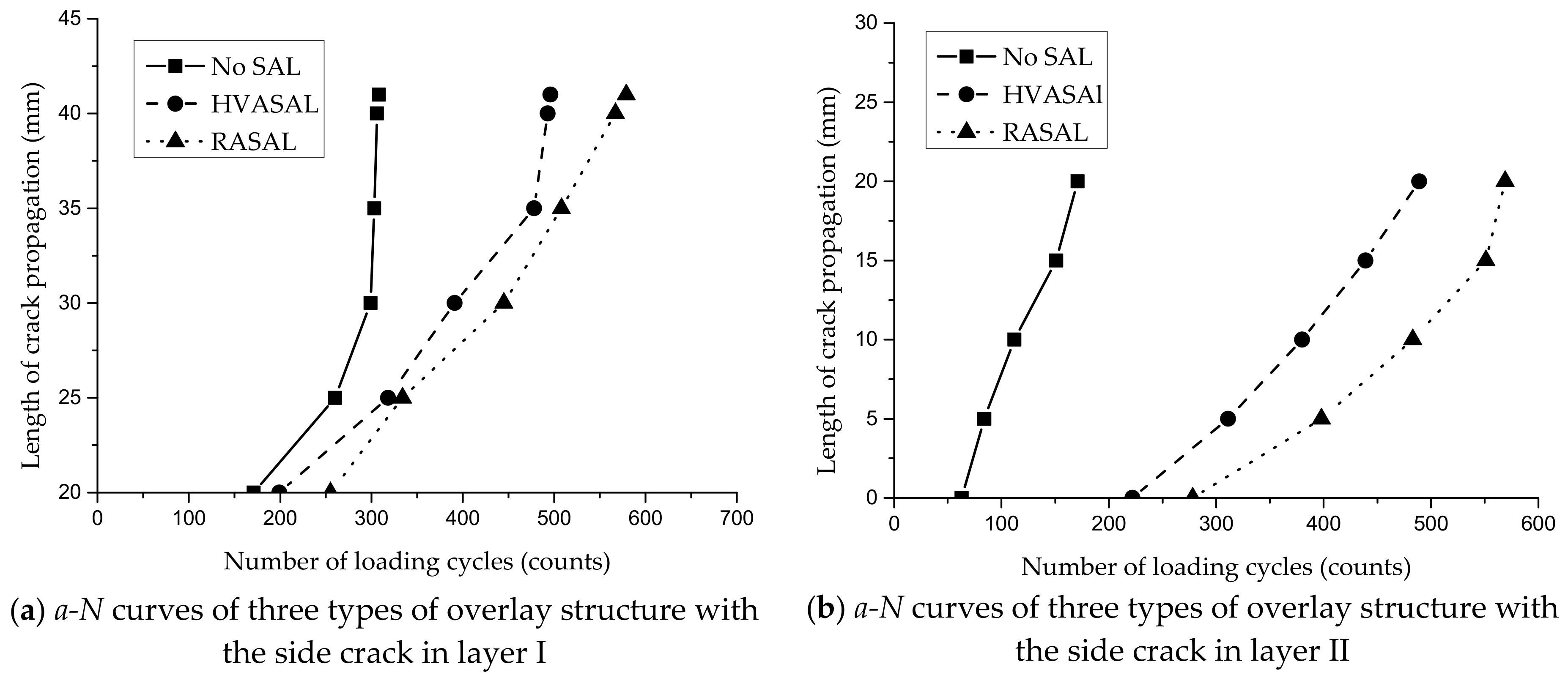
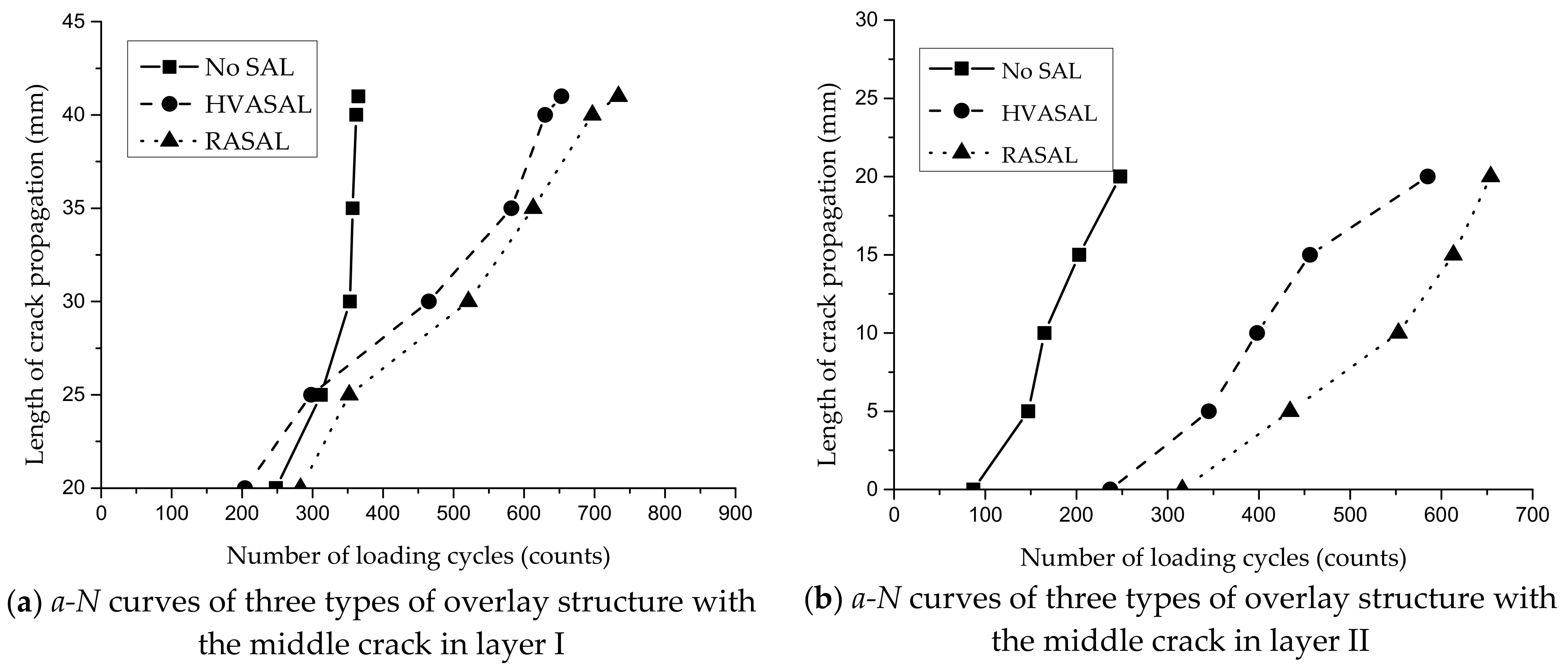
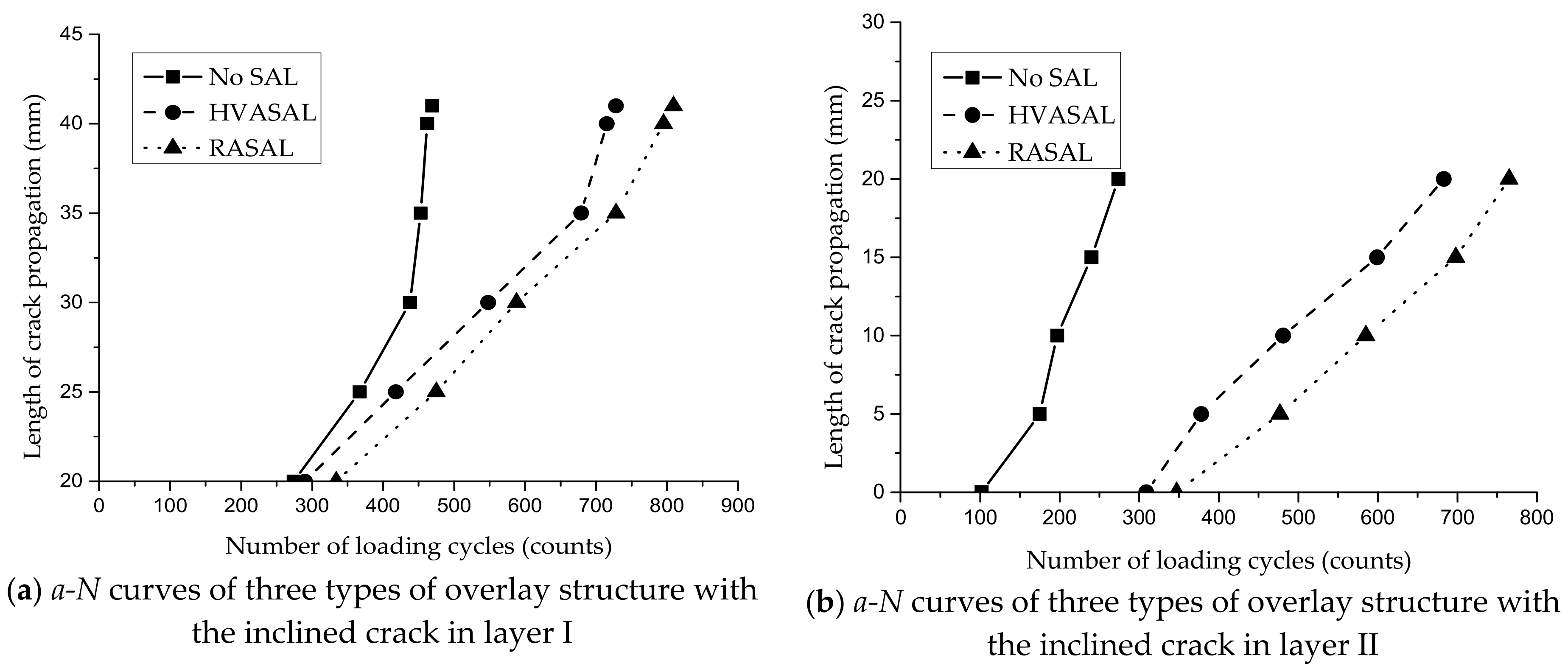
(1) Fatigue crack propagation experiments with the cyclic loadings acting in the middle of the specimens were carried out for three types of the old cement concrete asphalt overlay. The results show that for the fatigue numbers of the pre-crack of the three types of crack, the HVASAL type is 2.34 times, 3.15 times, and 2.84 times than that of the No SAL type; and the RASAL type is 3.25 times, 4.05 times, and 3.27 times that of the No SAL type. The results show that for the final fatigue lives of the three types of crack, the HVASAL type is 1.79 times, 1.61 times, and 1.55 times that of the No SAL type; and the RASAL type is 2.01 times, 1.87 times, and 1.72 times that of the No SAL type. After the stress-absorption layers were added, the fatigue lives of the structures increased significantly. The anti-crack performance of the RASAL is better than that of the HVASAL.
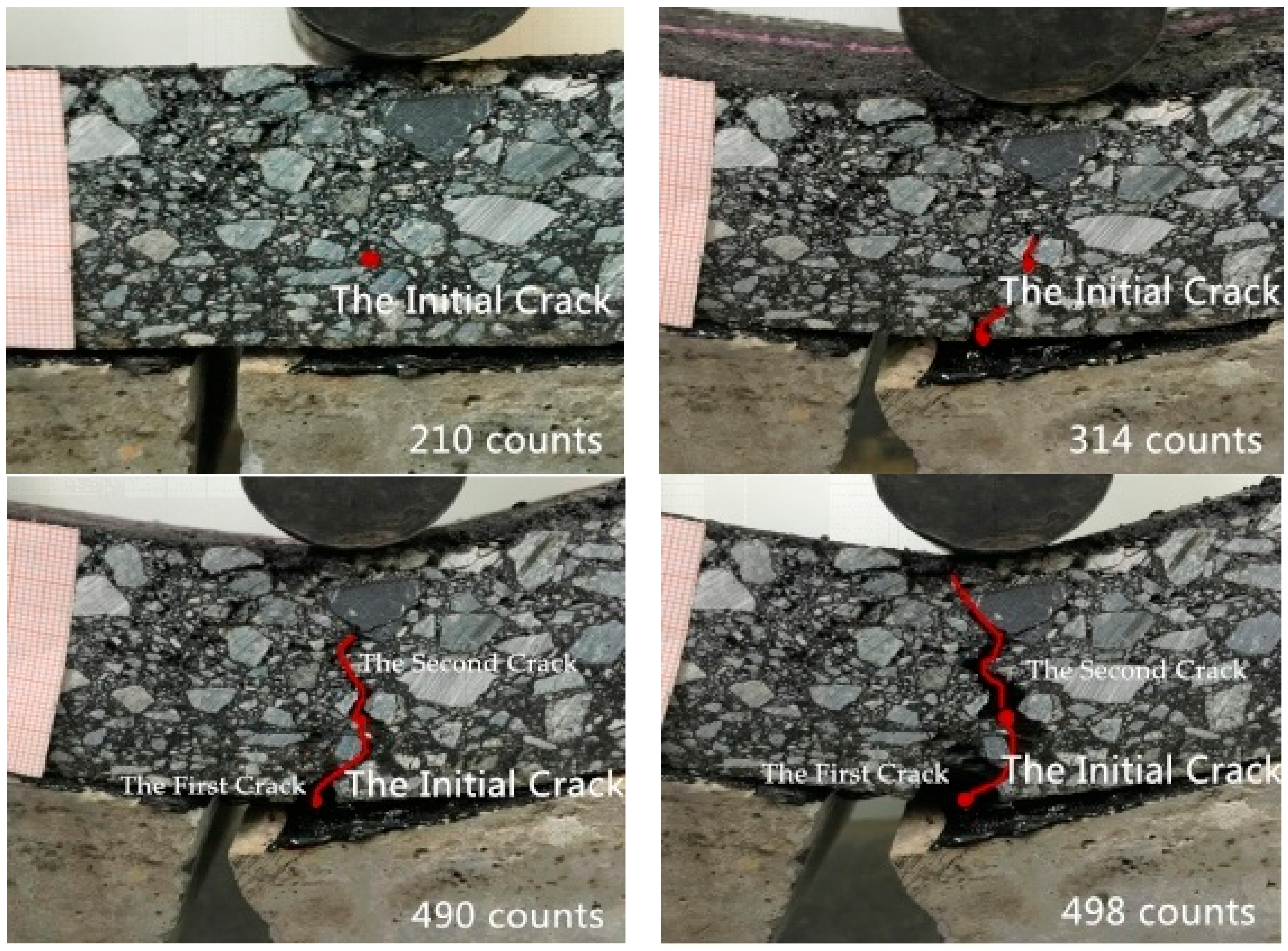
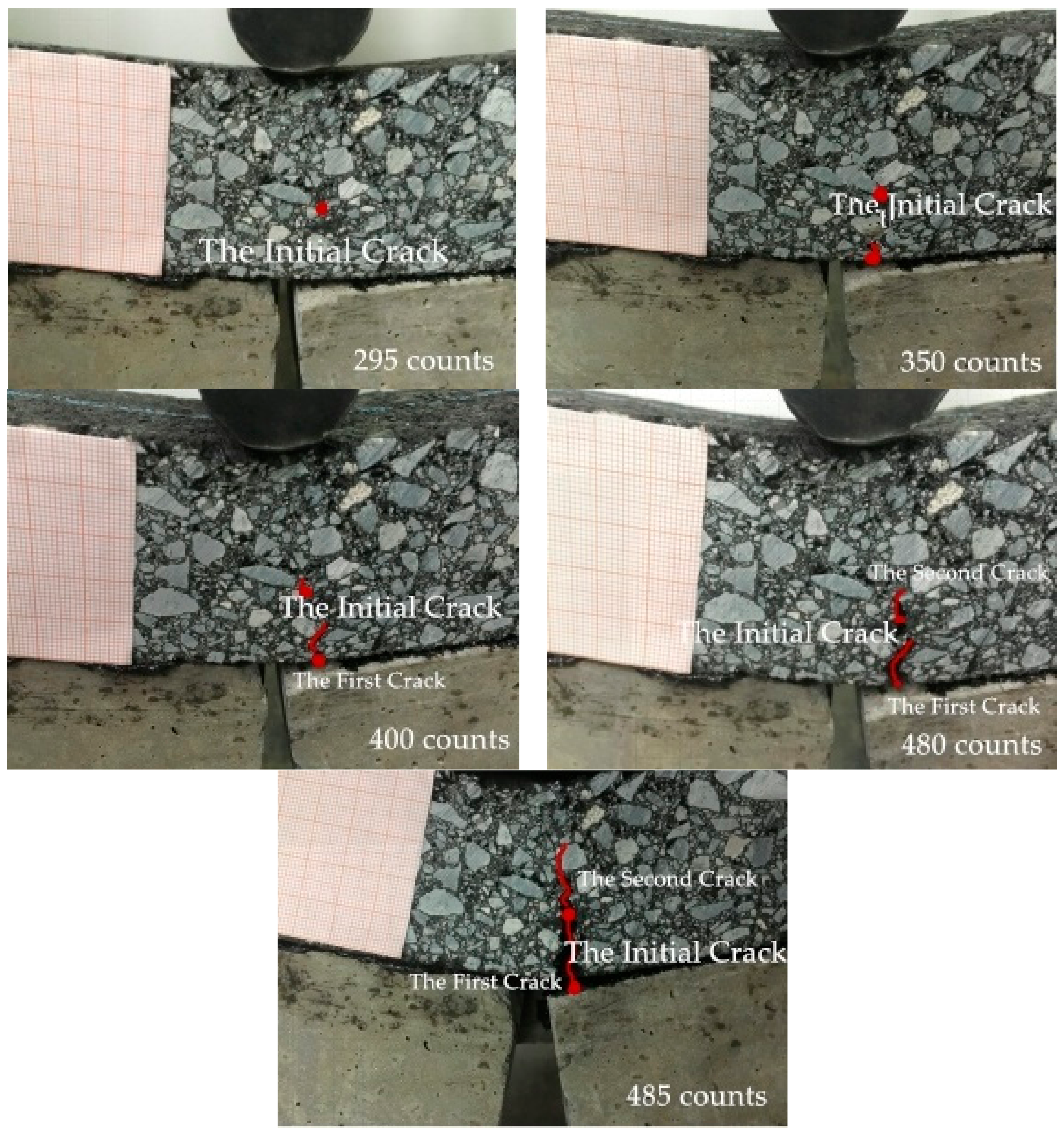
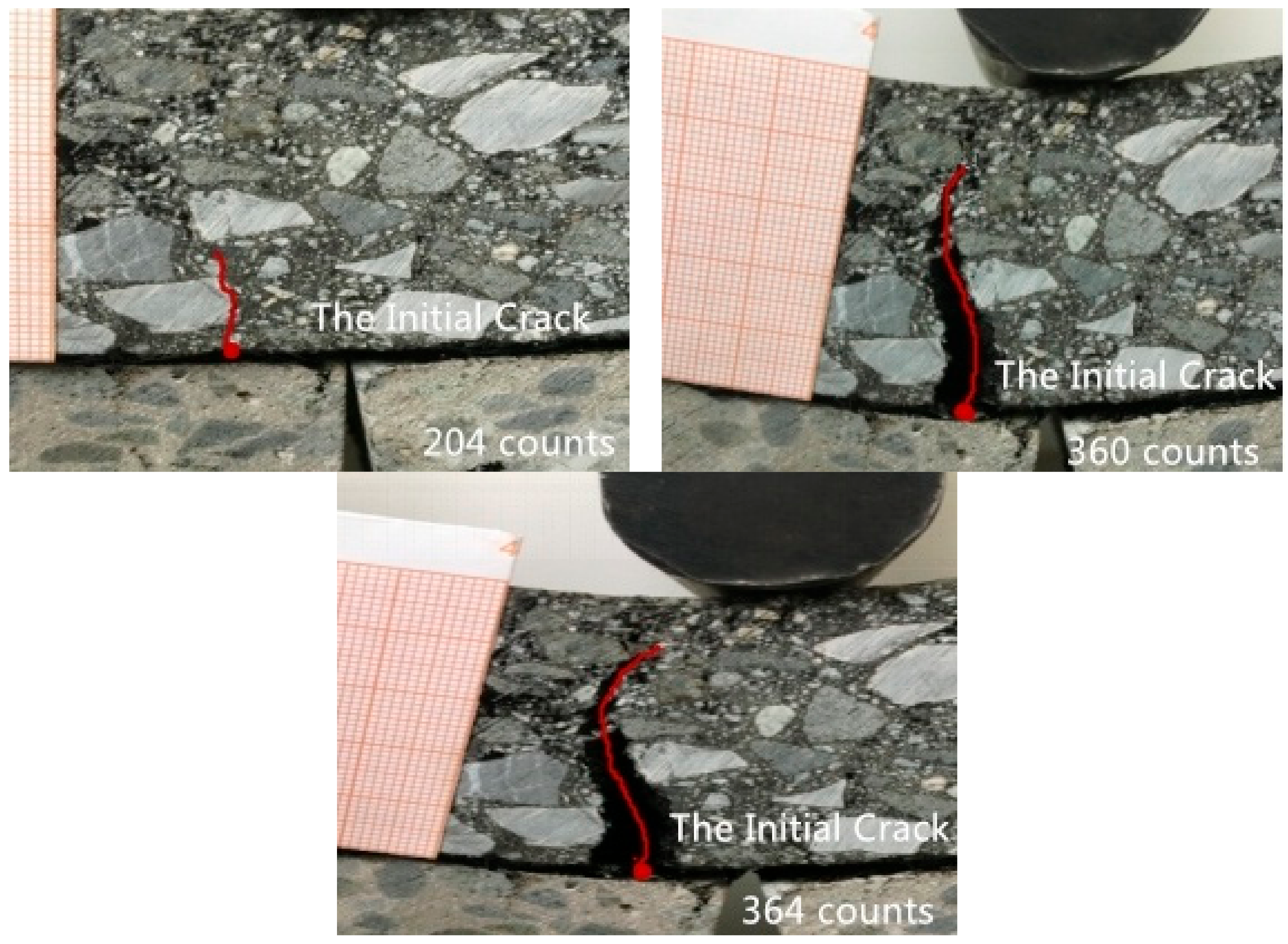
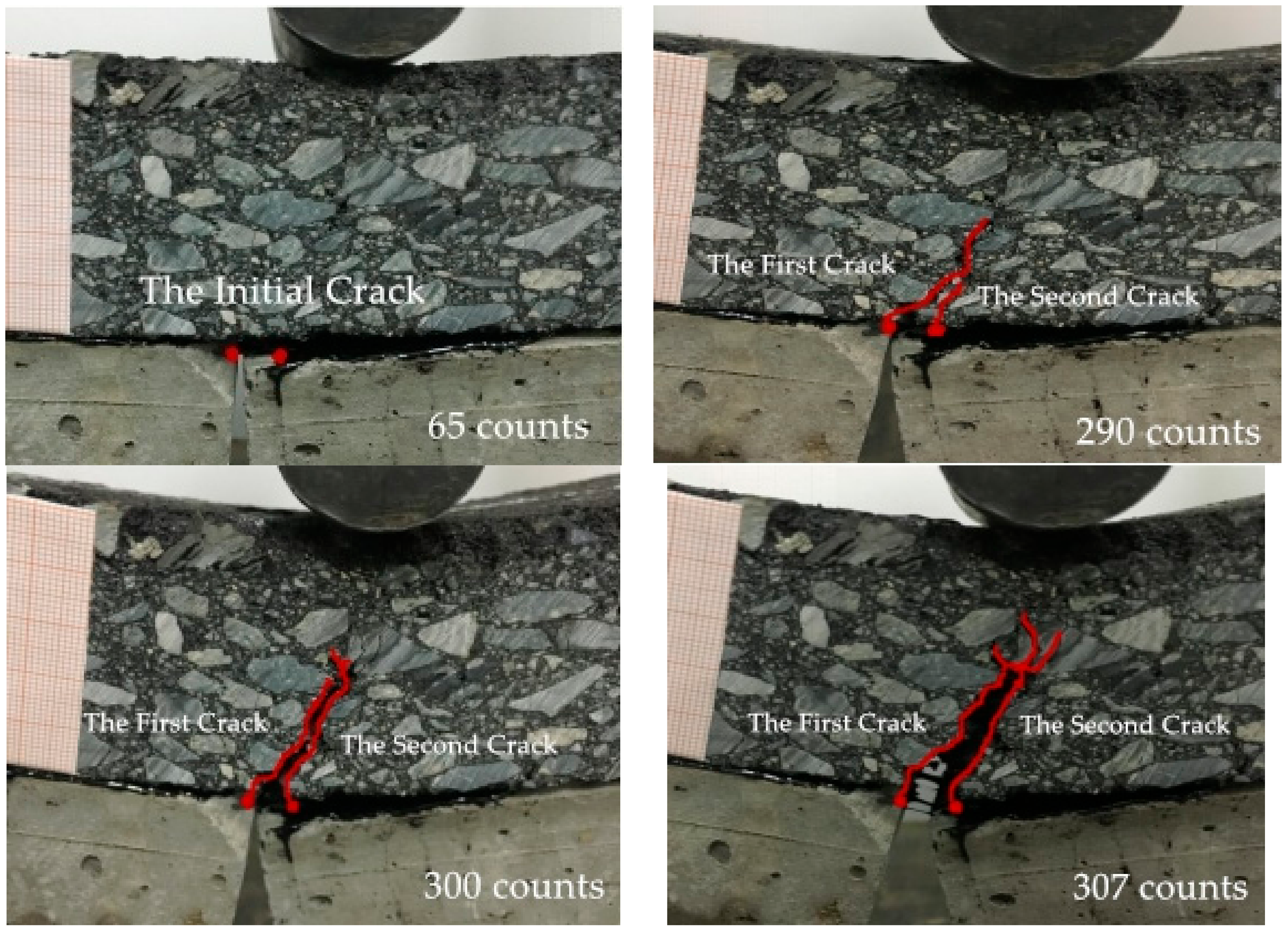
(2) The propagation processes, and the directions of the overlay cracks of the composite specimens, were analyzed and recorded. It was found that the cracks in the stress-absorption layer always initiated from the interface of layers I and II, then once there was a crack in the stress-absorption layer, the two cracks expanded at the same time. The crack propagation direction of the No SAL type structure was the same as the structure with a stress-absorption layer, but the crack expansion area was relatively concentrated. This demonstrated that the stress absorption layer could disperse the concentrated stress and reduce the peak stress caused by cracks in cement concrete, hence the reflection cracks were delayed.
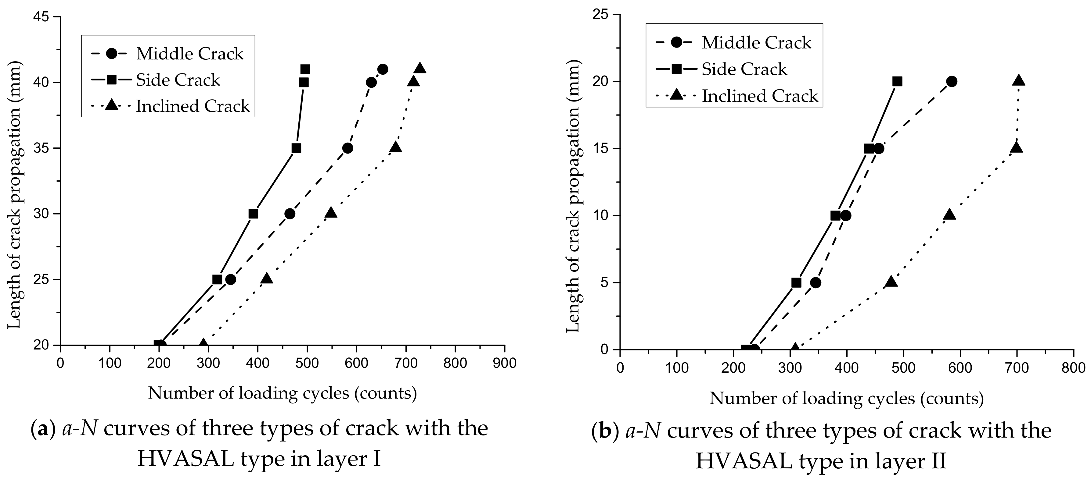
(3) The three types of structure and three types of crack (the middle crack, the side crack, and the inclined crack) have different effects on the fatigue properties of the asphalt overlay on the cement concrete basement. The inclined crack has the maximum fatigue life, the side crack has the minimum life, and the middle crack has an in-between life.
(4) These three test configurations provide three different mixed mode behaviors of cracks. As middle cracks occurred, there were two initial cracking points in the structure with the stress-absorption layer, with one located at the interface between the stress-absorption layer and the surface layer, and the other located at the bottom of the stress-absorption layer; subsequently, the stress-absorption layer and asphalt overlay would fracture. When there is no stress-absorption layer, the crack occurred along the interface of the cement concrete layer, passing through the overlay to all the specimens; the crack propagated in the direction of a certain lateral deviation and then had a straight upward expansion. For the side crack, the mechanism of the initial cracking points in the structure with stress-absorption layer were the same as that of the middle crack; one propagated vertically upward in mode I, the other propagated to the span center at a 45° angle in a mixed mode I and II. When there is no stress-absorption layer, the initiation of the crack was the same as that of the middle crack; that is, it propagated to the span center in a mixed mode I and II, extended directly below the pressure head, and then the specimen was destroyed. For the inclined crack, the mechanism of the crack propagation with the stress-absorption layer is the same as the former two types. When there is no stress-absorption layer, the crack occurred at the bottom of the asphalt overlay, and then some cracks appeared in the middle of the specimen due to the loading at the right of the crack, and propagated to the pressure head until the specimen failed. The mechanism of crack initiation is the same; however, the propagation direction and mode are different due to the relative loading position and the type of cracks.
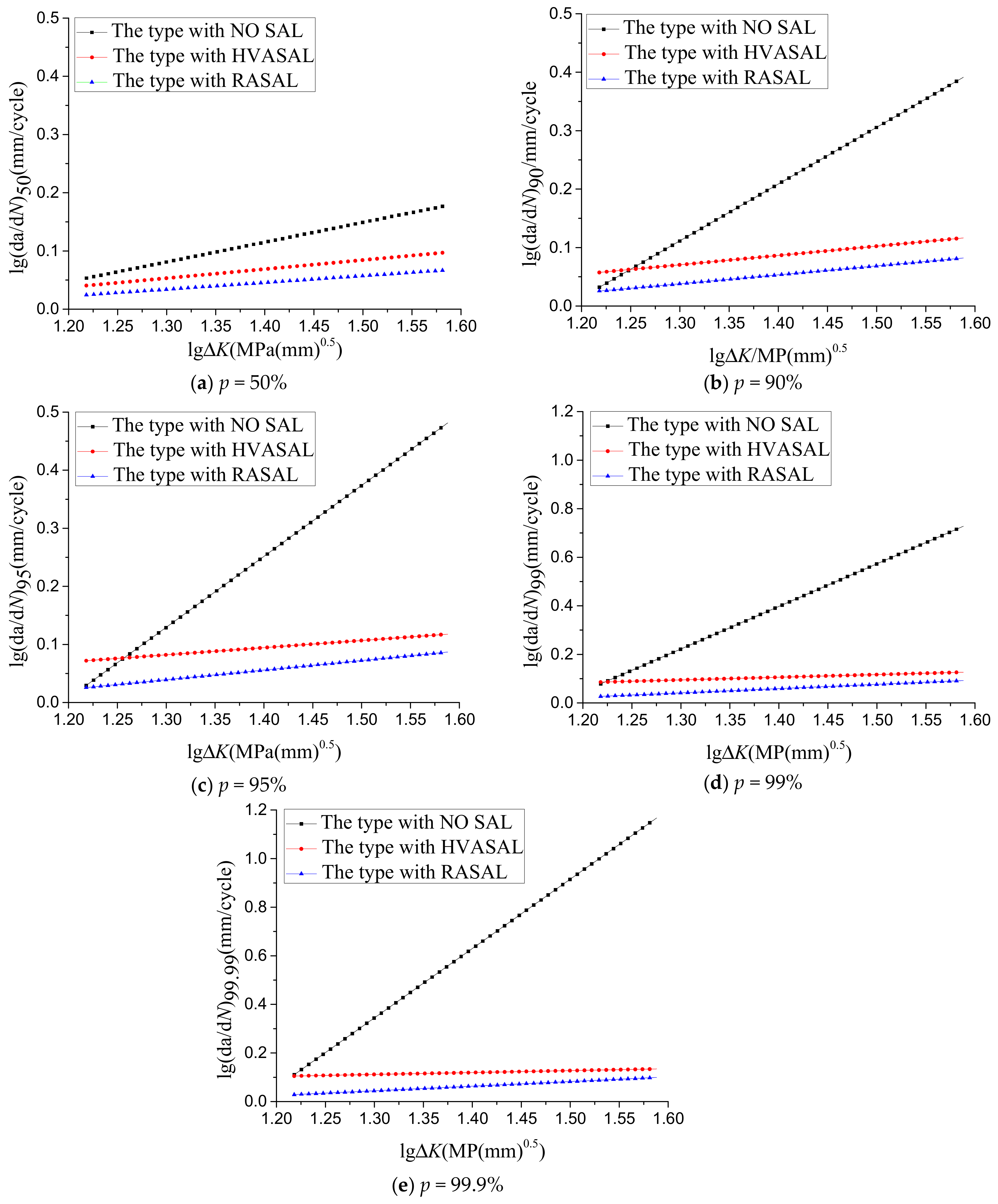
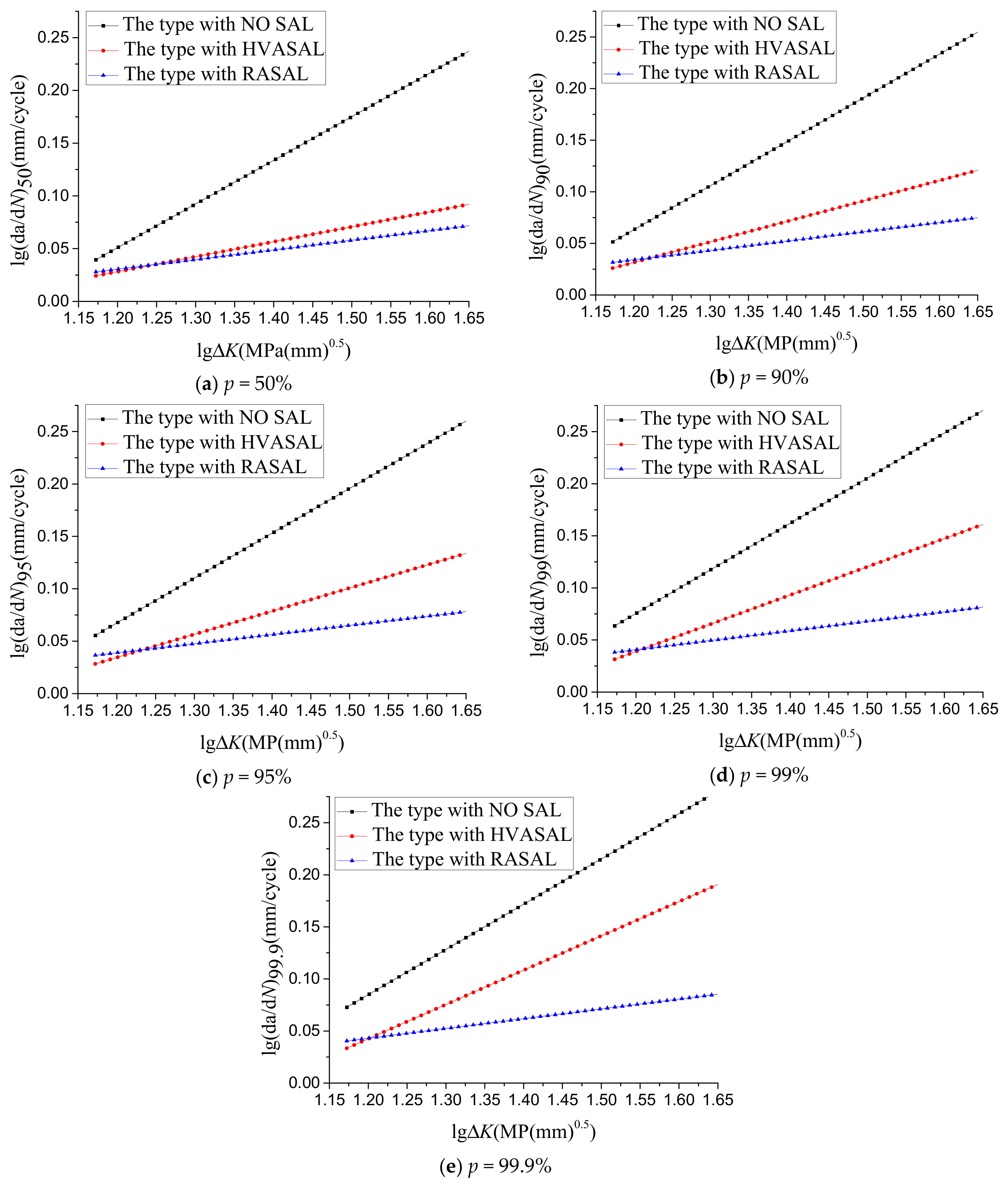
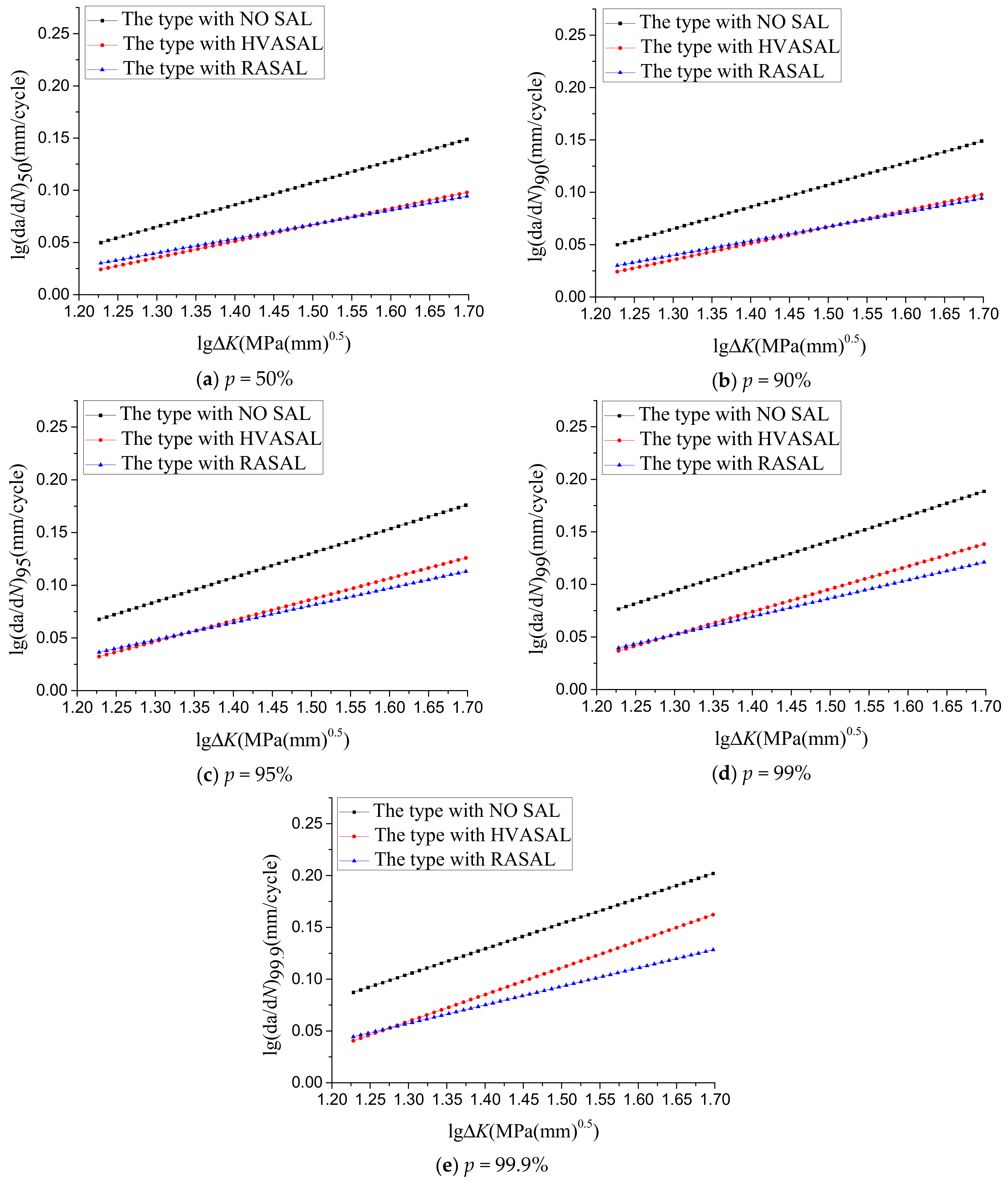
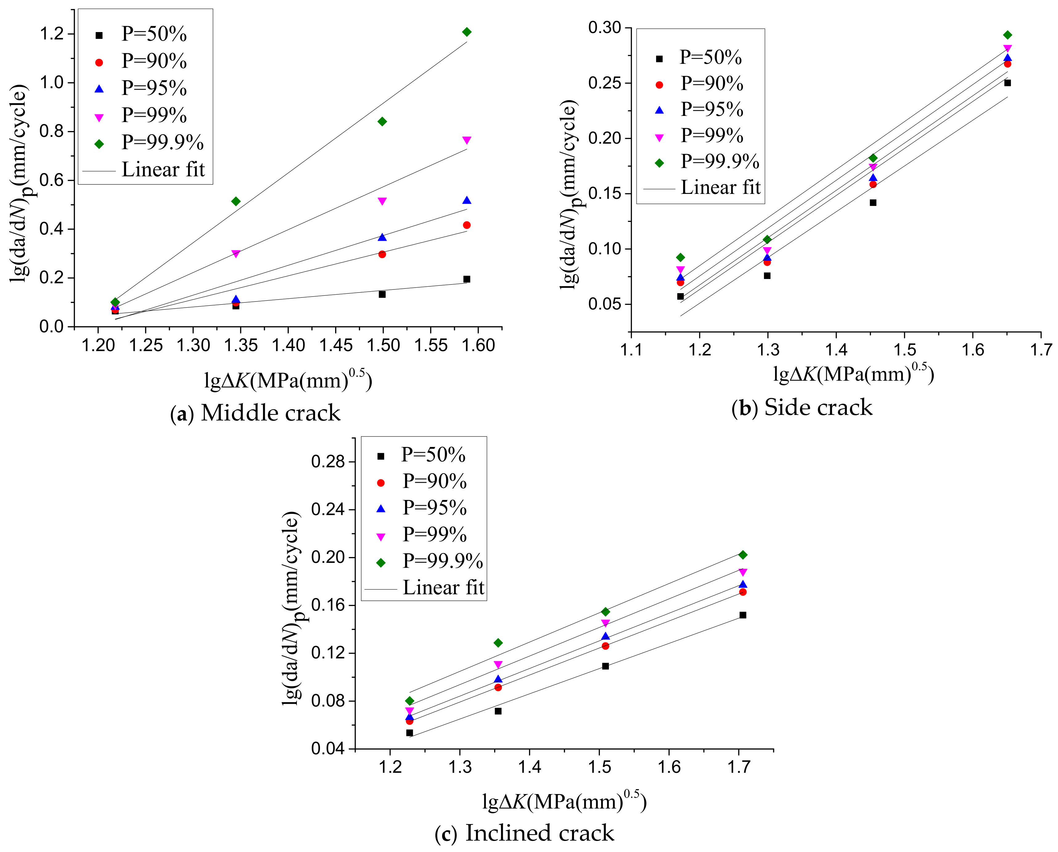
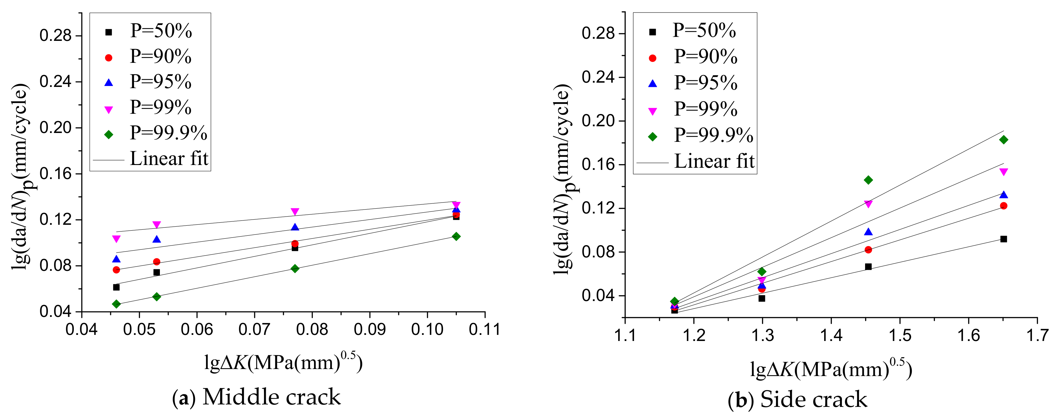
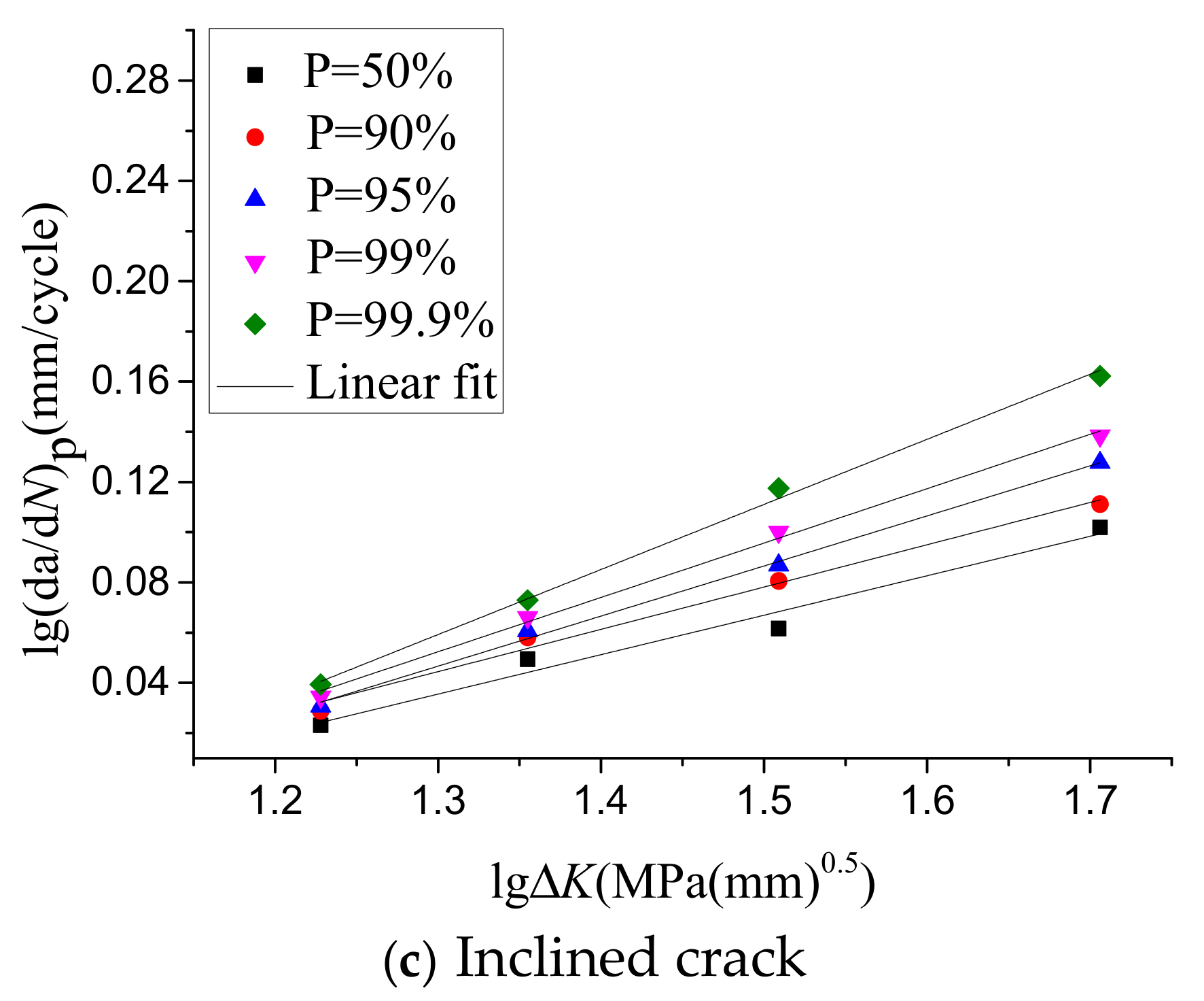
(5) The probability model quantifies the relationship between the crack propagation rate and ∆K. Two important parameters C and n, in Paris formula based on reliability, are consistent with the variation of the crack type in crack propagation. The effects of the three types of crack on the fatigue properties of the asphalt overlay are different. The reliability values of fatigue fracture by different crack types can be studied further to improve existing reliability theories, while solving practical problems.
(6) The p-da/dN probabilistic model can be used to study the effects of different cracks on C and n. Two important parameters of the Paris formula and the variation of crack type in crack propagation were obtained. Under different reliability, the parameter n is the largest in the No SAL type. The larger the slope is, the faster the crack growth, the worse the crack resistance, and the shorter the fatigue life. Therefore, the structure with the stress-absorption layer can effectively reduce the crack propagation rate, and effectively extend the service life of pavement.
(7) Asphalt mixture has an obvious brittle or quasi-brittle behavior at low temperature, so the fatigue crack propagation can be analyzed based on fracture mechanics. The critical fatigue crack propagation of the specimen with the middle crack occurs at the center of the bottom of the specimen, and the critical fatigue crack propagation of the specimens with the side crack and inclined crack occurs in the direction of maximum circumferential normal stress. There exist three stages of fatigue crack propagation (i.e., the crack initiation stage, the stable crack propagation stage, and the unstable fracture stage) in brittle or quasi-brittle materials, like the asphalt mixture at low temperature. After the cracking initiation, the toughness of the material increases with a stable crack growth until the unstable fracture happens. The increase of the toughness of material during the stable crack propagation is due to the cohesive force on the fictitious crack zone. The initial cracking point and the critical fracture point can be distinguished from a complete process of crack propagation, which can be described by the double-K criterion.

Author Contributions

Conceptualization, Y.S. and T.Y.; Methodology, Y.S.; Software, J.W.; Validation, T.Y., C.W., and X.S.; Formal analysis, C.W.; Investigation, T.Y.; Resources, Y.S.; Data curation, X.S.; Writing—review and editing, T.Y. and C.W.; Supervision, X.Y. and Y.S.

Funding

This research was funded by the National Natural Science Fund (51478276) and the Natural Science Foundation of Liaoning Province (20170540770).

Acknowledgments

This research was performed at the Shenyang Jianzhu University and the Institute of Transportation Engineering of Zhejiang University.

Conflicts of Interest

The authors declare no conflict of interest.

References

  1. Ozer, H.; AI-Qadi, I.L.; Wang, H.; Leng, Z. Characterisation of interface bonding between hot-mix asphalt overlay and concrete pavements: Modelling and in-situ response to accelerated loading. Int. J. Pavement Eng. 2012, 13, 181–196. [Google Scholar] [CrossRef]
  2. Ge, Z.S.; Wang, H.; Zhang, Q.S.; Xiong, C.L. Glass fiber reinforced asphalt membrane for interlayer bonding between asphalt overlay and concrete pavement. Constr. Build. Mater. 2015, 101, 918–925. [Google Scholar] [CrossRef]
  3. Zang, Z.-S.; Cai, Y.-X. Treatment Method and Evaluation of Interlayer Interface of Concrete Pavement Based on Rubber Asphalt Stress Absorption Layer. Highway 2017, 4, 9–11. [Google Scholar]
  4. Li, J.-B.; Gao, X.; Fu, X.-A.; Wu, C.-L.; Lin, G. A Nonlinear Crack Model for Concrete Structure Based on Extended Scaled Boundary Finite Element Method. Appl. Sci. 2018, 8, 1067. [Google Scholar] [CrossRef]
  5. Baek, J.; Ozer, H.; Wang, H.; AI-Qadi, I.L. Effects of interface conditions on reflective cracking development in hot-mix asphalt overlays. Road Mater. Pavement Des. 2010, 11, 307–334. [Google Scholar] [CrossRef]
  6. Dempsey, B.J. Development and Performance of Interlayer Stress-Absorbing Composite in Asphalt Concrete Overlays. Transp. Res. Rec. 2002, 1809, 175–183. [Google Scholar] [CrossRef]
  7. Wang, H.; Wu, Y.F.; Ye, S. Analysis of the Mode of Crushing and Stability in Old Cement Pavement during Asphalt Overlay Project. Appl. Mech. Mater. 2012, 204–208, 1941–1944. [Google Scholar] [CrossRef]
  8. Robertson, D. Numerical Simulations of Crushable Aggregates. Ph.D. Thesis, University of Cambridge, Cambridge, UK, 2000. [Google Scholar]
  9. Wang, H. A Comparative Study of Fatigue Performance to Resist Reflective Cracking among three Different Stress-Absorbing Materials. Appl. Mech. Mater. 2013, 303–306, 2625–2635. [Google Scholar] [CrossRef]
  10. Ogundipe, O.M.; Thom, N.H.; Collop, A.C. Evaluation of performance of stress-absorbing membrane interlayer (SAMI) using accelerated pavement testing. Int. J. Pavement Eng. 2013, 14, 569–578. [Google Scholar] [CrossRef]
  11. Moreno-Navarro, F.; Sol-Sánchez, M.; Rubio-Gámez, M.C. Reuse of deconstructed tires as anti-reflective cracking mat systems in asphalt pavements. Constr. Build. Mater. 2014, 53, 182–189. [Google Scholar] [CrossRef]
  12. Mao, C. Study on Formation Mechanism and Expansion Behavior of Crack in Asphalt Pavement. Ph.D. Thesis, Xinan Jiaotong University, Chengdu, China, 2004. [Google Scholar]
  13. Liao, W.-D. Study on Asphalt Overlay Structure and Material of Old Cement Concrete Pavement Based on Stress Absorption Layer. Ph.D. Thesis, Wuhan University of Technology, Wuhan, China, 2007. [Google Scholar]
  14. Luo, H.; Zhu, H.-P.; Chen, C.-Y. Study on Fatigue Test of Pre Cut Asphalt Mixture Trabeculae. J. Civ. Eng. Manag. 2008, 25, 47–50. [Google Scholar]
  15. Cai, Y.-X. Study on Structural Behavior and Road Performance of Stress Absorption Layer of Rubber Bitumen. Ph.D. Thesis, Chang’an University, Xi’an, China, 2016. [Google Scholar]
  16. Yang, Y.; Zhang, K.; Ji, S.-P. Study on Anti Reflective Cracking Performance of Rubber Asphalt Stress Absorption Layer. Chin. For. Highw. 2013, 33, 323–326. [Google Scholar]
  17. Zhao, Y.-T. Theoretical Analysis and Experimental Study of Stress Absorbing Layer in Semi—Rigid Pavement Reflective Crack Control. Mater’s Thesis, Hebei University of Technology, Wuhan, China, 2014. [Google Scholar]
  18. Tao, J. Study on Fatigue Behavior of Asphalt Overlay Structure of Old Cement Concrete Pavement under Traffic Load. Mater’s Thesis, Wuhan University of Technology, Wuhan, China, 2008. [Google Scholar]
  19. Cheng, Y. Study on Asphalt Overlay Structure of Cement Concrete Pavement with Stress Absorption Layer. Mater’s Thesis, Chang’an University, Xi’an, China, 2006. [Google Scholar]
  20. Zamora-Barraza, D.; Calzada-Pérez, M.A.; Castro-Fresno, D.; Vega-Zamanillo, A. Evaluation of anti-reflective cracking systems using geosynthetics in the interlayer zone. Geotext. Geomembr. 2011, 29, 130–136. [Google Scholar] [CrossRef]
  21. Guo, J.; Zhang, R.-H. Study on the Properties of Stress Absorption Layer of Rubber Bitumen. Guangdong Build. Mater. 2012, 28, 31–35. [Google Scholar]
  22. Hou, Y.-M. Experimental Study on Fatigue Performance of Stress Absorption Layer of Rubber Asphalt. Highw. Eng. 2009, 4. [Google Scholar] [CrossRef]
  23. Aliha, M.R.M.; Bahmani, A.; Akhondi, S. A novel test specimen for investigating the mixed mode I+ III fracture toughness of hot mix asphalt composites–Experimental and theoretical study. Int. J. Solids Struct. 2016, 90, 167–177. [Google Scholar] [CrossRef]
  24. Aliha, M.R.M.; Fazaeli, H.; Aghajani, S.; Nejad, F.M. Effect of temperature and air void on mixed mode fracture toughness of modified asphalt mixtures. Constr. Build. Mater. 2015, 95, 545–555. [Google Scholar] [CrossRef]
  25. Aliha, M.R.M.; Sarbijan, M.J.; Bahmani, A. Fracture toughness determination of modified HMA mixtures with two novel disc shape configurations. Constr. Build. Mater. 2017, 155, 789–799. [Google Scholar] [CrossRef]
  26. Ameri, M.; Nowbakht, S.; Molayem, M.; Aliha, M.R.M. Investigation of fatigue and fracture properties of asphalt mixtures modified with carbon nanotubes. Fatigue Fract. Eng. Mater. Struct. 2016, 39, 896–906. [Google Scholar] [CrossRef]
  27. Aliha, M.R.M.; Behbahani, H.; Fazaeli, H.; Rezaifar, M.H. Study of characteristic specification on mixed mode fracture toughness of asphalt mixtures. Constr. Build. Mater. 2014, 54, 623–635. [Google Scholar] [CrossRef]
  28. Sun, L.-J.; Wang, G.; Zhang, H.-C.; Liu, L.-P. Initiation and Propagation of Top-Down Cracking in Asphalt Pavement. Appl. Sci. 2018, 8, 774. [Google Scholar] [CrossRef]
  29. Li, S.-Q.; Wang, X.-C. Study on fatigue Simulation of reflection crack Development in Asphalt overlay. J. China For. Highw. 2009, 29, 190–193. [Google Scholar]
  30. Song, L.-X.; Wu, X.-H.; Song, L.-J. Research on Asphalt Overlay Material of Old Cement Concrete Pavement Based on Stress Absorption Layer. Highw. Eng. 2017, 42, 286–291. [Google Scholar]
  31. Wu, H.-Z.; Guo, H.-D.; Gao, D.-P. A Review on the Probability and Statistics Method of Fatigue Failure Life. Intensity Environ. 2002, 29, 38–44. [Google Scholar]
  32. Wang, K.-Q. Study on Reliability of Fatigue Crack Propagation under Different Stress Ratio. Ph.D. Thesis, Kunming University of Technology, Kunming, China, 2012. [Google Scholar]
Figure 1. Specimens of three types of crack with a stress-absorption layer (in mm).
Applsci 08 02093 g001
Figure 2. Specimens of three types of crack without a stress-absorption layer (in mm).
Applsci 08 02093 g002
Figure 3. Molded piece and finished specimen.
Applsci 08 02093 g003
Figure 4. Test machine with formed specimen.
Applsci 08 02093 g004
Figure 5. a-N curves of three types of overlay structure with the middle crack in two layers.
Applsci 08 02093 g005
Figure 6. Fatigue crack propagation of the middle crack of the rubber asphalt stress absorption layer (RASAL) type.
Applsci 08 02093 g006
Figure 7. Fatigue crack propagation of the middle crack of the No SAL type.
Applsci 08 02093 g007
Figure 8. a-N curves of three types of overlay structure with the side crack in two layers.
Applsci 08 02093 g008
Figure 9. Fatigue crack propagation of the side crack of the high viscous asphalt sand stress absorption layer (HVASAL) type.
Applsci 08 02093 g009
Figure 10. Fatigue crack propagation of the side crack of the No SAL type.
Applsci 08 02093 g010
Figure 11. a-N curves of three types of overlay structure with the inclined crack in two layers.
Applsci 08 02093 g011
Figure 12. a-N curves of three types of crack with the No SAL type.
Applsci 08 02093 g012
Figure 13. a-N curves of three types of crack with the HVASAL type in two layers.
Applsci 08 02093 g013
Figure 14. a-N curves of three types of crack with the RASAL type in two layers.
Applsci 08 02093 g014
Figure 15. Fitting results of three types of structure with different reliability values of the middle crack.
Applsci 08 02093 g015
Figure 16. Fitting results of three types of structure with different reliability values of the side crack.
Applsci 08 02093 g016
Figure 17. Fitting results of three types of structure with different reliability values of the inclined crack.
Applsci 08 02093 g017
Figure 18. Comparison of the fitting results and test results of three types of fracture of the No SAL type structure with different reliability values.
Applsci 08 02093 g018
Figure 19. Comparison of the fitting results and test results of three types of fracture of the HVASAL type structure with different reliability values.
Applsci 08 02093 g019aApplsci 08 02093 g019b
Figure 20. Comparison of the fitting results and test results of three types of fracture of the RASAL type structure with different reliability values.
Applsci 08 02093 g020
Table 1. Properties of asphalt.
PropertiesStandardValue
Penetration (25 °C, 100 g, 5 s)T0604—201170 (0.1 mm)
Softening pointT0606—201147 (°C)
Viscosity (177 °C)T0625—20113.8 (Pa·s)
Elastic recovery (25 °C)T0662—201172 (%)
Table 2. Aggregate gradation.
Sieve size (mm)9.54.752.361.180.60.30.150.075
Passing percentage10080.445.35.322.217.312.47.6
Table 3. Ultimate failure loads and fatigue test loads for three types of crack.
Crack TypeUltimate Failure LoadFatigue Test Load (kN)
Test Results (kN)Average Value (kN)Coefficient of VariationStandard Deviation
Middle Crack1.7211.7250.2505%0.0043200.690
1.723
1.731
Side Crack1.5381.5500.5818%0.0090190.620
1.558
1.554
Inclined Crack1.7651.7650.4033%0.0071180.706
1.759
1.771
Table 4. Fatigue loading times for three types of crack.
Overlay Structure TypeCrack Type
Middle CrackSide CrackInclined Crack
Initial Crack (mm)Final Crack (mm)Initial Crack (mm)Final Crack (mm)Initial Crack (mm)Final Crack (mm)
No SAL8736563308102469
HVASAL204653199496290728
RASAL283734255579334809
Table 5. lg ( d a d N ) p in No SAL type with different crack types.
Crack Type Δ K   lg ( d a d N ) 50   lg ( d a d N ) 90   lg ( d a d N ) 95   lg ( d a d N ) 99   lg ( d a d N ) 99.9  
Middle crack1.2180.06460.07060.08120.09020.1009
1.3450.08540.09960.10940.30290.514
1.4990.13270.29690.3630.51830.8412
1.5880.19510.41670.5150.76831.2085
Side crack1.1720.05710.06970.07380.0820.0924
1.2990.07580.0880.09180.09930.1086
1.4540.14190.15840.16390.17470.1823
1.6510.25020.26740.27240.28220.2936
Inclined crack1.2280.05350.06330.06640.07250.0802
1.3550.07160.09140.09780.11130.1287
1.5090.10920.12610.13370.14590.1547
1.7060.15190.17120.1770.18840.2023
Table 6. lg ( d a d N ) p in HVASAL type with different fracture types.
Crack Type Δ K   lg ( d a d N ) 50   lg ( d a d N ) 90   lg ( d a d N ) 95   lg ( d a d N ) 99   lg ( d a d N ) 99.9  
Middle crack0.0460.06130.07650.08520.10420.0468
0.0530.07430.08350.10240.11650.0531
0.0770.09560.09930.1130.12790.0776
0.1050.12270.12470.12870.13340.1056
Side crack1.1720.02670.02980.03070.03260.0348
1.2990.03750.04620.0490.05480.0621
1.4540.06660.08210.09780.12470.146
1.6510.09190.12240.13170.15420.1829
Inclinedcrack1.2280.02310.02880.03060.03440.0393
1.3550.04940.0580.06070.06610.0729
1.5090.06160.08060.08690.10010.1175
1.7060.10190.11120.12770.13840.1623
Table 7. lg ( d a d N ) p in RASAL type with different fracture types.
Crack Type Δ K   lg ( d a d N ) 50   lg ( d a d N ) 90   lg ( d a d N ) 95   lg ( d a d N ) 99   lg ( d a d N ) 99.9  
Middle crack1.2180.02960.03260.03350.03520.0373
1.3450.03290.03740.03880.04160.045
1.4990.05450.060.06170.0650.0689
1.5880.07190.09120.09770.1040.1123
Side crack1.1720.02830.03180.03290.03490.0375
1.2990.03960.04330.05440.05650.0591
1.4540.05310.05680.05780.05990.0624
1.6510.07220.07520.07840.08220.0864
Inclined crack1.2280.02740.03330.03520.0390.0439
1.3550.05170.05740.05910.06250.0666
1.5090.06760.07850.08190.08860.0969
1.7060.09490.10990.11440.12250.1289

