Article

Activation Process of ONU in EPON/GPON/XG-PON/NG-PON2 Networks

1
Department of Telecommunication, Brno University of Technology, Technicka 12, 616 00 Brno, Czech Republic
2
Department of Optical Networks, CESNET a.l.e., Zikova 4, 160 00 Prague, Czech Republic
*
Author to whom correspondence should be addressed.
Appl. Sci. 2018, 8(10), 1934; https://doi.org/10.3390/app8101934
Submission received: 2 October 2018 / Revised: 11 October 2018 / Accepted: 13 October 2018 / Published: 16 October 2018

Abstract

:
This article presents a numerical implementation of the activation process for gigabit and 10 gigabit next generation and Ethernet passive optical networks. The specifications are completely different because GPON, XG-PON and NG-PON2 were developed by the International Telecommunication Union, whereas Ethernet PON was developed by the Institute of Electrical and Electronics Engineers. The speed of an activation process is the most important in a blackout scenario because end optical units have a timer after expiration transmission parameters are discarded. Proper implementation of an activation process is crucial for eliminating inadvisable delay. An OLT chassis is dedicated to several GPON (or other standard) cards. Each card has up to eight or 16 GPON ports. Furthermore, one GPON port can operate with up to 64/128 ONUs. Our results indicate a shorter duration activation process (due to a shorter frame duration) in Ethernet-based PON, but the maximum split ratio is only 1:32 instead of up to 1:64/128 for gigabit PON and newer standards. An optimization improves the reduction time for the GPON activation process with current PLOAM messages and with no changes in the transmission convergence layer. We reduced the activation time from 215 ms to 145 ms for 64 ONUs.

1. Introduction

Passive optical networks (PONs) are the most promising solution for access networks. Because the European Union is seeking broadband access and continually rising bandwidth requirements for end users, some technologies are not sufficient, such as asymmetric digital subscriber line (ADSL) or wireless fidelity (WiFi). The current research goal is to not only use optical fibers for data transmission, but also for other special services, such as an accurate time, stable frequency and optical sensing for infrastructure defense [1,2].
The first specification of PON was approved in 1998 as the asynchronous transfer mode PON (APON) [3]. The basic topology, a cascade connection of splitters in the optical distribution network (ODN), corresponds to the first specification [4]. The Czech Republic is obliged to develop a broadband access Internet technology with a transmission speed of at least 30 Mbit/s (downstream direction) for current households and 100 Mbit/s for new customers by 2020. A proper technology for the main purpose is gigabit PON (GPON) technology and/or Ethernet PON (EPON). At present, EPON technology is not very popular around the world due to the decreasing price and better efficiency of GPON technology. Furthermore, the International Telecommunication Union (ITU) has more standards of PONs that are compatible with the previous standards. The ITU’s last standard next generation PON Stage 2 (NG-PON2) can transfer 40 Gbit/s (by 4 λ , each with 10 Gbit/s), but the Institute of Electrical and Electronics Engineers (IEEE) currently works on the first PON specification at 100 Gbit/s (by 4 λ , each with 25 Gbit/s). Note that ITU and IEEE are not compatible due to different encapsulation methods.
The rest of this paper is structured as follows. Section 2 introduces related works. Section 3 provides an overview of the GPON and EPON physical layer. Section 4 presents the activation processes for the G, XG, NG-PON(2) and EPONs. Section 5 presents the simulation model and a discussion of the results. Finally, Section 6 concludes the paper.

2. Related Works

In recent years, many publications on EPON have been published. Most of them involve the multi-point control protocol (MPCP) and energy saving. MPCP and energy saving issues belong to a transmission convergence layer of EPONs. The article [5] evaluates the exact mean packet delay for the MPCP. The authors proposed a reservation interval allocation method for the REPORTmessage. This message reports total queue size occupancy in ONU. The works [6,7] presented an EPON autodiscovery mechanism for fast network and service recovery and for scheduling traffic in the upstream direction. The mechanism improves the registration bandwidth efficiency from 0.13 to 0.6 with an arbitrary number of optical network units (ONUs), but it does not solve the activation process in an EPON. Other articles [8,9,10] considered the quality of service (QoS) and parameters in EPONs.
The authors in [11] proposed a Very High Speed Integrated Circuit Hardware Description Language (VHDL) implementation of the ONU autodiscovery process for EPONs. They moved the simplest autodiscovery process out of the ONU, which can be extended to data transfer in time slots via a VHDL implementation. The article [12] focused on dynamic bandwidth allocation (DBA) to provide QoS in an EPON and 10G-EPON coexistence scheme by distributed dynamic scheduling PON (DDSPON). The works [13,14,15] presented the latest phenomena in the EPON, which is energy saving for the ONU. On the one hand, ONU power consumption is not paid for by an Internet service provider (ISP), but by customers. On the other hand, Internet accessibility is not continuously needed by various customers throughout the day/night/weekends/holidays. Conversely, customers may want to be online at unexpected times when necessary. Each energy saving leads to a decrease in the power consumption bill. We evaluated the activation process in [16,17] for the GPON. The article [16] involved the activation process regarding the final verification by measurements. We have not considered the EPON standard for the comparison. Our simulation was designed only for the GPON, but the current model contains the EPON standard. Although the standards are different, both are found all over the world. In our paper [18], we provided the simulation of the transmission convergence layer in the next generation PONs. We implemented our own numerical model in MATLAB for the next generation PON (XG-PON). The work [19] evaluated the transmission convergence layer of GPON and the next generation PON (XG-PON). The results proved that the encapsulation method of ITU standards is highly efficient. For instance PON could be one of the solutions for the support of a cloud-radio access network (C-RAN), as described in [20,21]. The main contribution of this article is to demonstrate the importance of the activation process in passive optical (ITU and IEEE) networks and to reduce the total activation time of the ONU in GPON network with the current transmission convergence scheme and control messages format.

3. GPON and EPON Networks

The basic information on the transmission rate, used wavelengths, the maximum number of connected users and the actual range of the network is found in Table 1 (see the GPON column). The transfer medium is described in ITU’s Telecommunication standardization sector ITU-T recommendation G.652, which describes a single-mode optical fiber. The optical signal is transmitted bidirectionally using the wavelength-division multiplexing (WDM)-based transfer medium via a single fiber or unidirectionally via two fibers. The non-return-to-zero (NRZ) code is used. The transmitter uses multi-longitudinal mode (MLM) and single-longitudinal mode (SLM) lasers. The attenuation classes of the GPON are defined in [22]:
  • Class A: 5–20 dB
  • Class B: 10–25 dB
  • Class C: 15–30 dB
These attenuation specifications do assume the worst case scenario regarding losses on connectors, passive optical devices, fiber splices and optical fiber attenuation.
The GPON contains optical line termination (OLT), the ONU and the ODN. The OLT unit is the central unit and controls all communications on the network. ONU presents the end of the optical part of the ODN. In general, the ODN contains all transmissions between the OLT and ONU. The total minimum optical return loss (ORL) at the reference point R/S(before ONU) in the ODN must be below 32 dB. The maximum differential path losses (the difference between the largest and smallest loss in a single ODN) should be 15 dB [22,23].
The basic information on the transmission rate, used wavelengths, the maximum number of connected users and the range of the network can be found in Table 1 (see the EPON column where the point to multipoint (P2MP) topology is used). In the standard, the physical layer is divided into four sublayers: reconciliation sublayer (RS), physical medium attachment (PMA), physical medium dependent (PMD), medium dependent interface (MDI) and gigabit media independent interface (GMII). Descriptions of these sublayers and a further description of the associated interfaces are in [24]:
  • MDI specifies the physical media and the mechanical and electrical interfaces between the transfer medium and the physical layer devices.
  • PMD is responsible for linking to the transfer medium, and it is placed directly over the MDI. EPON uses WDM-based single-mode optical fibers. Two types of interfaces are supported, specifically: 1000BASE-PX10 with an overlapping distance of 10 km and 1000BASE-PX20 with an overlapping distance of 20 km.
  • PMA provides functions for transmission, clock restart and phase alignment. This sublayer is primarily designed to specify the clock and data recovery (CDR) time interval.
  • The physical coding sublayer (PCS) provides functions for link-coding of data (bits) that may be transmitted over the physical medium. EPON uses 8B/10B encoding [25].
  • GMII specifies the interface between the media access control (MAC) layer and the physical layer.
  • RS provides mapping of signals from GMII for the link layer.

4. xPON Activation Processes

The activation process describes the steps in which an inactive ONU connects or reconnects to a PON [26]. The activation process includes three phases, specifically: parameter learning, serial number acquisition and ranging. During the learning parameter phase, the ONU acquires the operational parameters that are needed in the upstream transmission. During the serial number acquisition phase, OLT discovers a new ONU (by serial number) and assigns an ONU identifier (ONU-ID) to it.
The ONU round trip delay (RTD) is the time interval between the downstream frame transmission and the corresponding upstream transmission burst from the given ONU. The RTD consists of a propagation delay that is directly proportional to the length of the fibers from the ONU and the response of the ONU. To ensure that transmission bursts from different ONUs are ordered at the interface of the same upstream GPON transmission convergence layer (GTC) frame, the delay time is assigned to each ONU to postpone the transfer of the upstream burst to the time not used for a common response time. This response time is called the equalization delay (EqD), and for each given ONU, the OLT is calculated based on the RTD measurement and consequently transmitted during the ranging state.
To avoid collisions with the upstream bursts transmitted during acquisition of the serial number and the range of the newly-connected ONU, the OLT must temporarily suppress the upstream transmission of the active ONU for the time that the arrival of upstream bursts from the new ONU is assumed. This time interval is referred to as the quiet window.

4.1. GPON Activation States

The following information is based on the recommendation [26].
State O1, Initialstate: In this state, the ONU switches on, waits for the downstream signal and synchronizes with it afterwards. Initially, a loss of signal (LoS) is set up to indicate the loss of a signal or a frame. It is also important for the synchronization machine of the ONU and OLT in the downstream direction to perform correct synchronization. In the synchronization state, ONU starts in the so-called Huntstate, in which it searches for the physical synchronization (PSync) field. When an error-free PSync array is found, the ONU moves to the next state, called the Pre-sync state, and sets the counter Nto one. The ONU then searches for the next PSync array that follows the previous one. For each error-free PSync array, the counter is incremented by one. If the ONU receives a corrupted PSync, it returns to the Hunt state. If the N counter in the Pre-sync state is equal to M1 (the recommended value for M1is two), the ONU moves to the Syncstate and begins processing the information from the physical control block downstream (PCBd) header. If the ONU in the Sync state receives M2 (the recommended value for M1 is five) consecutive frames with a corrupted PSync, it can declare the loss of the downstream signal and return to the Hunt state. The ONU then deletes all transmission convergence (TC) layer-based parameters known from the previous session such as: ONU-ID, default allocation identifier (Alloc-ID), delay compensation and Burst Headerparameters. Once the downstream transmission is received, the LoS and loss of frame (LoF) are cleared, and the ONU moves to the O2 state.
State O2, Standbystate: After State O1, the synchronization in the downstream direction is provided, yet the upstream direction synchronization is required and essential. Downstream transmission is received by the ONU and waits for global network parameters. Once the upstream overhead message is received, the ONU sets up the assigned parameters and moves to the O3 state.
State O3, Serialnumber state: In this state, the OLT requests broadcast ONUs to send their serial number. To prevent collisions with the normal traffic, the OLT creates as mentioned above a quiet window with a duration of 250 μ s by sending a frame with an empty bandwidth map (BWmap) field. Subsequently, the previously mentioned SN request is sent (i.e., a request to send a serial number) with a random delay set between 0 and 48 μ s. As a reply to the SN request, the ONU uses the serial number ONU message to enable the OLT to examine and detect the serial number. In addition, the OLT uses the AssignONU-ID message to assign the ONU-ID. Once the number is assigned, the ONU moves to the next state. The OLT can also send an Extended Burst Lengthmessage to all connected ONUs and hand over the extended overhead parameters. However, if the ONU receives this message before the request to send the serial number, it ignores such a message. In this state, the TO1 timer is used to cancel any unsuccessful activation attempt by setting the time during which the ONU can remain in this particular state. The recommended TO1 value is 10 s. After such a time, the ONU moves to the O2 state.
State O4, Rangingstate: Transmission in the upstream direction from different ONUs must be synchronized with the boundaries of the upstream GTC frame. To ensure the appearance of the ONUs, they are set at the same distance from the OLT, and the equalization delay for each ONU is required. The equalization delay is measured when the ONU is in this state. During this particular state, a quiet window with a duration of 202 μ s is created. The OLT sends a ranging request, and the ONU replies with a Serial Numbermessage. Furthermore, the OLT sends the Ranging Timemessage, in which the allocated equalization delay is transmitted. Once this message is received by the ONU, it moves to its working state. In such a state, the TO1 timer is used.
State O5, Operationstate: In this state, the ONU can now send data, physical layer operations and administration and maintenance (PLOAM) messages according to the OLT instructions. Once the network is equalized and all the ONUs are working with the correct equalization delay, all upstream bursts will be synchronized among all ONUs.
State O6, POPUP state: An ONU enters this state when any of the LoS or LoF alarms (if the signal is lost or the frame is poorly assembled) is detected. Therefore, if this condition occurs, the ONUs immediately stop sending data. After the POPUP status occurs, the ONU first attempts to retrieve the optical signal, recover the synchronization of the GTC frame and remove the LoS/LoF alarm. The ONU goes either to the Operationstate or to the Rangingstate according to the particularly targeted POPUP messages. If the ONU receives the targeted POPUP message, it returns to the Ranging State. If the ONU cannot restore the optical signal or reset itself to recover the GTC frame synchronization, it does not receive a targeted POPUP message and is moved to the Initialstate. This is where the TO2 timer is used (the recommended time for the timer is 100 ms).
State O7, Emergencystop state: An ONU that receives a Disable Serial Numberwith the “deactivate” option goes to the emergency stop state and shuts off the laser. During this state, the ONU is not allowed to send any data. If a failure on the deactivated ONU is resolved, the OLT can activate the ONU to return it to its functional state. The activation is accomplished by sending the Disable Serial Number message with the “enable” option. Subsequently, the ONU returns to the Standbystate, and all parameters are discarded and retrieved.

4.2. XG-PON Activation Process

As mentioned in Section 4.1, the principles of the activation process for XG-PON are basically identical to those for GPON and are defined by the recommendations [26,27].
State O1, initial state: The ONU is in this state immediately upon switching on or after switching from other states when there is an error requiring a return to the initialization state. The transmission is switched off at this time, and all the previously set TC layer parameters (e.g., ONU-ID) are cleared. Synchronization in the downstream direction is provided by the synchronization machine. The ONU starts in the Hunt State, where it uses the downstream signal to search for the PSync pattern stored in the physical synchronization block downstream (PSBd). If it is found, the ONU verifies that a 64-bsuperframe counter (SFC) structure, which is also found in PSBd and secured by a self-repairing hybrid error correction (HEC), is valid. If the SFC is valid, the ONU stores its values and moves to the Pre-Syncstate. With the next successful validation (at this point, only 62 bits out of the total number of received 64 bits are sufficient), the ONU moves to the Sync state. However, if any of these validations fail, the ONU returns to the Hunt state. The unit remains in the Sync state (the unit has already been successfully synchronized) as long as the PSync and SFC authentication are successful. If the authentication fails, the ONU moves to the Re-Sync state. It moves to the Sync state only after successful validation. The recommended value for the M parameter is three. However, if M-1consecutive physical interface (PHY) frames validating the PSync or SFC fail, the ONU declares a loss of synchronization with the downstream frame, discards the saved SFC copy and returns to the Hunt state. This process is illustrated in Figure 1. Once synchronized with the downstream PHY frame, the ONU moves to the next state.
State of O2-3, Serial Number State: In this state, the ONU activates its transmitter in a burst mode and waits for messages from OLT. The ONU analyzes the PLOAM section of the downstream XG-PON transmission convergence layer (XGTC) frame and begins to learn the burst profile specified in the Profilesection of the message. Upon receiving a serial number grant, it reports with the XGTC frame carrying the Serial Number ONU PLOAM message to send its serial number. As soon as it receives an AssignONU-ID PLOAM message with its serial number, it sets the allocated ONU-ID together with the other assigned parameters and moves to the next state. After receiving the Disable Serial Number PLOAM message (for its serial number or for all ONUs), it moves to the EmergencySTOPState. If OLT already knows the ONU that is returning to the network (e.g., during recovery, power failure, etc.), a problem with the Assign ONU-ID PLOAM message could occur. Therefore, the ONU can go directly to the state called the Ranging State when activated without responding to the serial number grant request.
State O4, Ranging state: In this state, the ONU receives a ranging grant with a known burst profile. Consequently, the XGTC frame containing the RegistrationPLOAM message is transmitted as a response. The ONU analyzes the PLOAM section of the downstream XGTC frame and responds only to the following messages: Profile, Ranging Time, Deactivate ONU-ID and Disable Serial Number. If the ONU receives the Ranging Time message with the absolute equalization delay, it moves to the next state. In this state, the TO1 timer is used to cancel unsuccessful attempts by limiting the time that the ONU can stay in that state. The recommended value for the TO1 timer is 10 s. If it expires, the unit discards the associated ONU-ID, as well as all other parameters, and returns to the Serial Number state.
State O5, Operationstate: The ONU already transmits data and PLOAM messages in the upstream direction as instructed by the OLT. At this point, the OLT can create additional connections with the ONU if they are required. Once the network is in operation and all ONUs are working with their assigned equalization delay, all upstream bursts are synchronized with all ONUs.
State O6, IntermittentLODS state: The ONU will move to this state from the Operation state when it does not synchronize with the downstream signal. Upon entering this state, the ONU will start the TO2 timer (the recommended value for this timer is 100 ms). After the timer expires, the ONU returns to the Initial state.
State O7, Emergency Stop State: The ONU moves to this state if it receives the Disable Serial Number message with the “Disable” option. In this state, it switches off the laser and rejects all TC settings (ONU-ID, equalization delay, burst profiles, etc.). The ONU keeps the downstream synchronization machine running and analyzes the XGTC frames in the downstream direction (at this point, however, it is forbidden to pass any downstream data or send any upstream data). If the problem is resolved, the OLT can re-enable the ONU and bring it back to normal operation by sending the Disable Serial Number with the “enable” option. As a result, the ONU returns to the Initial state.

4.3. NG-PON2 Activation Process

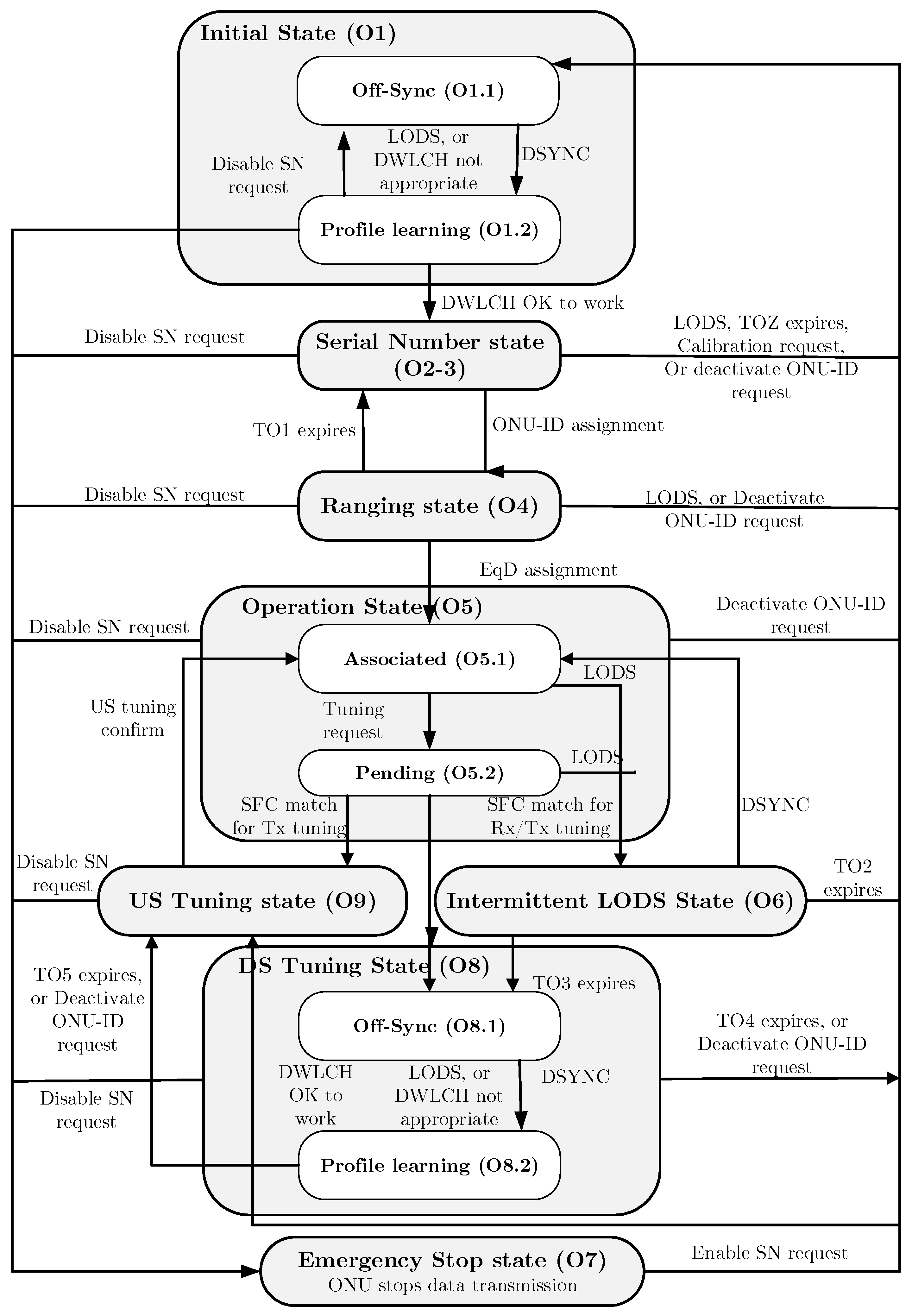
The activation process is provided by time and wavelength division multiplexing transmission convergence (TWDM-TC) and is defined by the recommendation [28]. In the NG-PON2 standard, there are two options for the PLOAM channel. The in-band option is a classical PLOAM message transmission, and the auxiliary management and control channel (AMCC) option is mandatory for ONUs that do not meet the specified calibration limits for a given upstream wavelength channel (see Figure 2).
State O1, Initial state: The ONU is in this state when it is turned on. At this point, scanning and downstream channel calibration occur. The unit can also move to this state when deactivated, or when the emergency stop is on. The transmitter is off and the previously set parameters, such as the ONU-ID, burst profiles and equalization delay, should be deleted. Next, the synchronization machine (see Figure 2) is started. The substate, O1.1, is called Off-Sync. In this state, the ONU searches for downstream synchronization attempts. As soon as the synchronization is finished, the ONU moves to the next substate, O1.2, known as the Profile Learning. When enough information has been gathered, the ONU evaluates the downstream wavelength of the channel. If the channel is suitable for activation, the ONU continues the process and moves to the next state. However, if it is not suitable, it searches for an alternative channel and returns to the O1.1 substate, retaining system and channel information, but discarding information about the burst profile.
State of O2-3, Serial number state: In this state, ONU activates its transmitter and tries to tune the upstream wavelength channel in line with the downstream wavelength channel. Once the ONU meets the minimum requirements for calibration accuracy for the required upstream wavelength channel, it receives a request known as an SN in-band grant to send the serial number. The message Serial Number ONU is sent as a response to this request. However, if the ONU does not meet the minimum calibration accuracy, it receives a request to send the AMCC type number. In this case, the AMCC Serial Number ONU PLOAM message is sent as a response to this request. Next, the ONU waits for an OLT response, which may be in the form of an Assign ONU-ID message, a Calibration Requestor an Adjust Tx Wave-length PLOAM message. Depending on the received message or request, the ONU either stays in this state and tunes the transmitter, returns to the initial state O1 so that another TWDM channel can be calibrated or moves to the next state and continues with the activation process. In this state, the ONU starts a discovery timer called TOZ. If this timer expires without the ONU receiving a response from the OLT, it returns to the O1 state. In this case, the unit discards all the accumulated system, channel and burst profile information.
State O4, Ranging state: In this state, the ONU responds to the ranging grant. If it receives a burst profile ranging grant from the previous Burst Profile PLOAM message, the FS burst carrying the Registration PLOAM message is transmitted. As soon as the ONU receives the Ranging Time message with the equalization delay, it moves to the next state. In this state, it starts the T01 timer with the recommended duration of 10 seconds. If the timer expires, the ONU deletes the allocated ONU-ID along with all the previously set parameters and returns to the O2-3 state, while retaining the collected profile information.
State O5, Operation state: In this state, the ONU is already processing frames in the downstream direction and transmits bursts in the upstream direction as instructed by the OLT. This particular state is divided into two substates. The entry point of this state is O5.1, which is called Associated. The ONU is associated with a specific TWDM channel, and the no Tuning ControlPLOAM message awaits processing. Another substate, O5.2, is called Pending. While the ONU completes upstream transmission of SDU units whose fragmentation already began in the previous subset, it performs further fragmentation if necessary and transfers any unfragmented SDU units.
State O6, Intermittent LODS state: The ONU can reach this state from the O5 state in the case of downstream synchronization loss. Upon entering this state, the unit turns on the timer. When wavelength channel protection (WLCP) is enabled, the TO3 timer is turned on. If the WLCP is turned off, the TO2 timer is turned on. If the downstream signal is restored before any of the two timers expire, the ONU returns to the O5 state. However, once the TO2 timer expires, the ONU moves to the initial state O1. If, on the other hand, the TO3 timer expires, the ONU moves to the O8 state (to be described; see below).
State O7, Emergency Stop State: The ONU moves to this state if it receives the Disable Serial Number message with the “Disable” option on. In this case, it deactivates the laser. However, it keeps the downstream synchronization machine running and analyzes the PLOAM section of the downstream FS frames (however, at this point it is forbidden to pass any downstream data or send any upstream data). If the ONU receives the Disable Serial Number message with the “enable” option on, it returns to the O1 state.
State O8, Downstream tuning state: In this state, the ONU tries to restore the transmission using the new TWDM channel while maintaining the configuration of the TC layer except for its burst profiles. In this state, the TO4 timer is used. When it expires, the ONU returns to the initial O1 state and discards the TC layer configuration. In the O8.1 substate, also known as Off-Sync, the ONU tunes its receiver and tries to synchronize with the downstream signal. As soon as it is synchronized, it moves to the O8.2 substate, known as Profile Learning. In this state, it analyzes the downstream framing sublayer (FS) frame and starts collecting information about the system, channel and burst profile. When enough information has been gathered, the ONU will evaluate the downstream wavelength of the channel. If this channel is suitable for activation, the ONU continues the activation process and moves to the next state. However, if it is not suitable, it searches for an alternative channel and returns to the O8.1 substate, retaining the system and channel information, but discarding the burst profile information.
State O9, Upstream tuning state: As long as the ONU is in this state, it waits for a feedback from the OLT and performs a fine-tuning of its transmitter. Subsequently, it moves to the O5 state. In this state, the TO5 timer is started. If this timer expires, the ONU returns to the initial state.

4.4. EPON Activation Steps

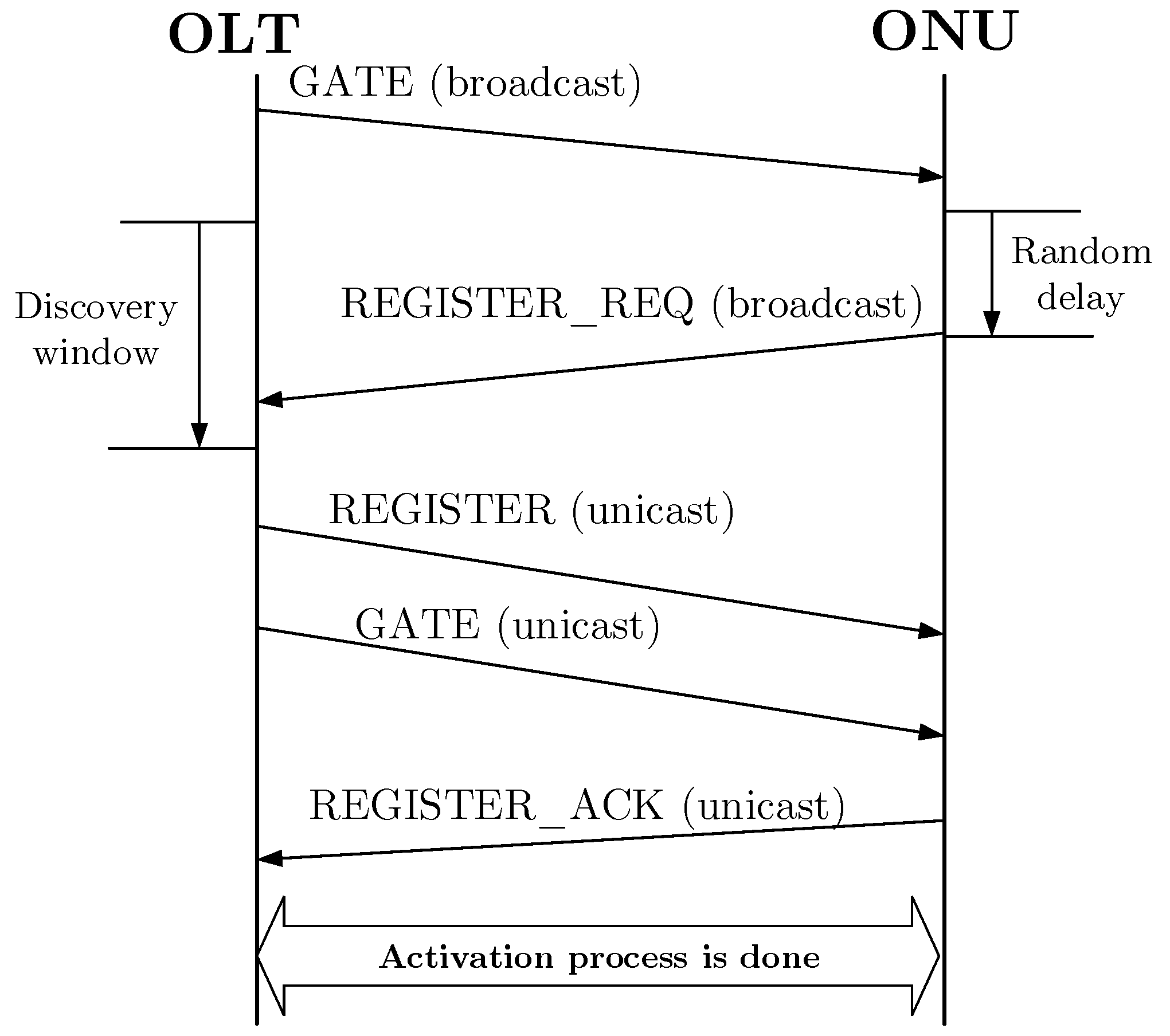
The following subsection evaluates the EPON activation process according to [24]. The MPCP defines the autodiscovery mechanism used to detect the newly-connected ONUs, a circular delay and a MAC address [29]. This process is controlled by the OLT unit, which periodically creates an available discovery window, during which time it gives inactive units the ability to log in to the OLT. This periodicity is not specified by the standard and therefore depends on individual implementation. Autodiscovery uses the following four messages: GATE, REGISTER REQ, REGISTER and REGISTER ACK. These messages are transmitted in the MPCP frame. The autodiscovery process consists of four steps, which are illustrated in Figure 3.
Step 1: The Discoveryagent decides to initiate the discovery process and assigns a discovery window (the time interval when none of the initialized ONUs can send data). The Discovery Agentinitiates the discovery process using the Discovery GATE message, which includes the starting time and the length of the slot. During the forwarding of the GATE discovery message, the MPCP stores the OLT time.
Step 2: Only previously uninitialized ONUs respond to the GATE message. After receiving such a message, the ONU sets the local time according to it. If the OLT clock reaches the starting time that is also included in the GATE discovery report, the ONU waits for a randomly selected time and then forwards the REGISTER REQ message. Accidental delays can lead to collisions when initiating multiple ONUs. The REGISTER REQ message contains the ONU source address and the time used to send the message from the ONU. When the OLT receives a REGISTER REQ message, it detects the MAC address and the circular delay.
Step 3: After analyzing and verifying the REGISTER REQ message, the OLT sends the message REGISTER directly to the given ONU using the MAC address obtained during the previous step. The REGISTER message contains a unique logical link identifier (LLID) that is assigned to all ONUs. Next, the OLT sends the GATE message to the same ONU.
Step 4: After the REGISTER and GATE ON messages are received, the REGISTER ACK confirms that an acceptance of the previous messages has been sent. The REGISTER ACK should be sent in the time interval granted by the GATE message.

5. Simulation Results

Simulations were performed in a MathWorks MATLABTM environment for each standard separately according to their recommendations. A description of the triggering processes of the individual standards that constitute the simulations is in Section 4.
In the first instance, the user set some of the parameters influencing the simulation. At first, the standard to be simulated was chosen. The available choices were the following: GPON, XG-PON, NG-PON2, EPON and the optimized GPON. Furthermore, the number of ONUs to be connected to the OLT at the specified interval (the maximum number of ONUs that can connect was determined by the selection of the standard mentioned previously) and the length of the distribution network also need to be chosen at the specified interval needs. Then, the total activation time was calculated. The output was visualized as a graph that shows how long the activation of the ONUs that were connected to the OLT occurred.

5.1. Simulations for ITU Standards

The ITU activation processes are always described within the TC layer and are divided into several states. The simulation was based primarily on the ONU’s activation description (see Section 4). Information was transmitted in PLOAM messages for 125 μ s. The OLT operating status was the time granted to the ONU by the OLT to process the received message. It had a duration of 750 μ s. The total ONU activation time consisted of the following: a synchronization time that was given to the synchronization state machine, the time of the transmission of the messages and their processing by the ONU, the generated window, the propagation delay that was added to each message, the calculated equalization delay and the activation time of all previously activated ONUs. All time constants were specified by the standards [24,26].
In Stage O1 of the GPON standard, synchronization with the downstream signal provided by the synchronization state machine was required. In the simulation, only the initial synchronization was solved. In all cases, two consecutive frames with the correct PSync were needed. Random and incorrect PSync were generated. If the PSync was correct, the N variable was incremented. Otherwise, it was set to zero. Synchronization ended when N was equal to M (M was set to two). Next, the OLT operation status followed. Because the simulation did not consider collisions, there were no standard timers to prevent the ONU from remaining in any part of the activation for an indefinite time.
Propagation delay was the time it took to move a message from the OLT to the ONU. It depended on the length of the distribution network to the unit and the transmission rate in the environment. In the simulation, the propagation delay was added to the downstream and upstream messages and was calculated for each unit separately according to the following formula:
T p d = l i c n ,
where l i represents the distance between the ONU and OLT, c is the speed of light and n is the refractive index.

5.1.1. GPON

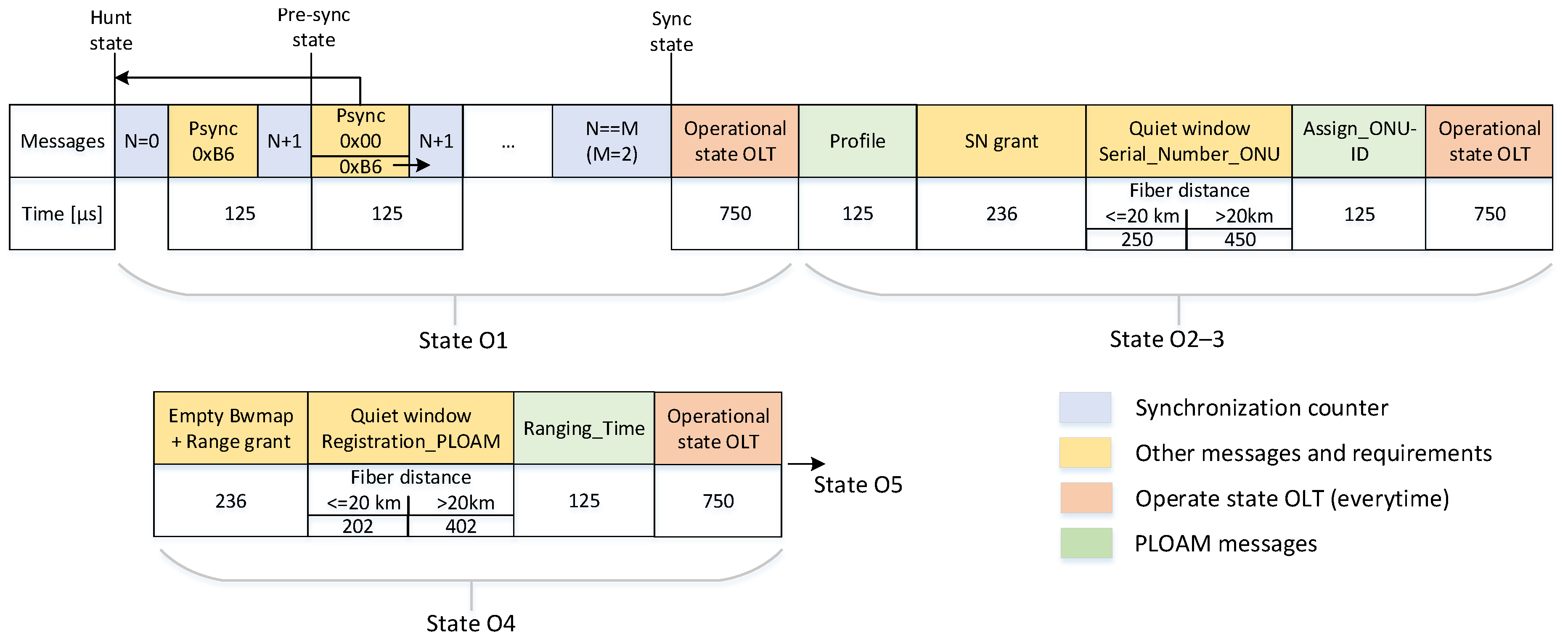
The simulation was based primarily on the description of the ONU activation process described in Section 4.1. The Activation passed through four different states until it reached the fifth state in which it was finally possible to transfer the data. The time flow and the transmitted messages are shown in Figure 4. As shown, all downstream PLOAM messages were sent three times. State O1 and State O2, described previously, were unified for each ONU. After creating a quiet window, the ONUs sent messages with their serial numbers. The unit whose message was received by the OLT first was activated, and the other units were forced to wait. Activation took place until all units were finally connected. In the O4 state, the equalization delay was measured and subsequently transmitted by the Ranging Time message. The ONU must use this delay in its message transfer. Because the GPON standard measures this delay, the computation performed during the simulation presented in this work must be considered as exploratory in nature. The computation was based on information proposed in [26].
E q D i = T e q d R T D i ,
where T e q d is the so-called zero-distance E q D (offset between the downstream frame and the obtained frame that was requested). It can be computed as follows [26]:
T e q d = 2 T p d + R s p T i m e + P r d + U S f r a m e ,
where R s p T i m e is the response time of the ONU with its value set to 35 μ s, P r d is the pre-assigned delay set to 202 μ s and U S f r a m e is the upstream frame duration.
R T D is the usual delay expressed as [26]:
R T D i = 2 T p d + R s p T i m e .
During the simulation, the program lists the current status, the transmitted messages and the total time of activation of the given ONU in milliseconds.

5.1.2. XG-PON

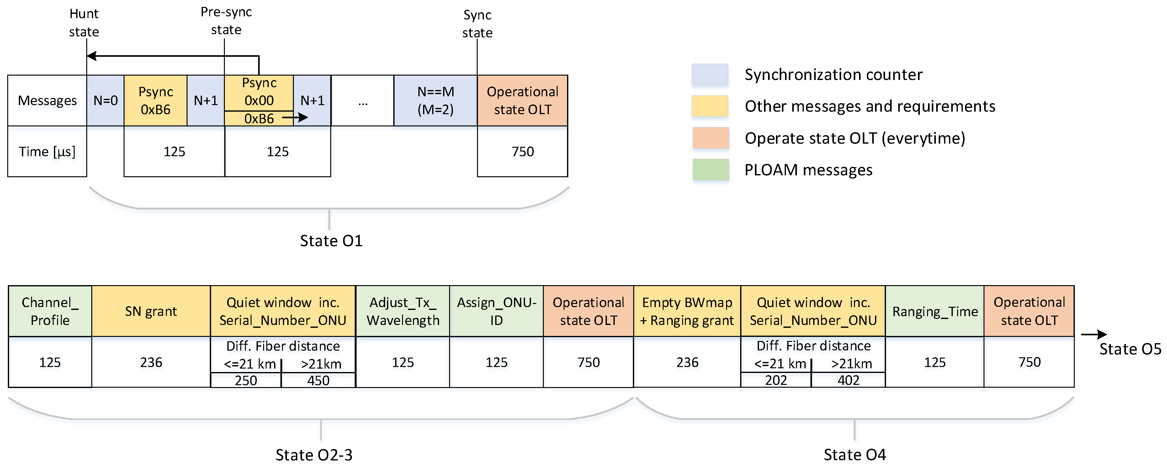
In principle, activation for XG-PON is based on GPON. However, there have been several major changes such as: downstream PLOAM messages are only sent once; States O2 and O3 are merged together into a single state; some PLOAM messages are altered; and the duration of the quiet window depends on the fiber spacing distance, which is the value determined by the difference between the fiber length of the most remote and the nearest ONU from the OLT. In our simulation, the most remote unit was set by the user with the highest possible value of 40 km. At a 20-km difference, the quiet window duration was the same as for GPON, and at a distance of 40 km, the quiet window was increased by 200 μ s. The nearest unit was set to 1 km. The entire activation process is described in Section 4.2, and the messages along with the transmission process are shown in Figure 5.
The basic equation for the computation of equalization delay was the same as in the case of GPON. However, the calculation of the individual components varied, as for XGPON E q D i were computed as [27]:
T e q d R s p T i m e max + ( L m i n + D m a x ) · n 1577 + n 1270 c ,
where L m i n represents the minimum distance, D m a x is the maximum differential distance and the refractive index values for the wavelengths n 1577 and n 1270 are given as follows: n 1577 = 1.4686 and n 1270 = 1.4677. RTD is defined as [27]:
R T D i = T p d n 1270 + 1577 n 1270 R s p T i m e i .

5.1.3. NG-GPON2

For simulation of NG-PON2 (the activation process is described in Section 4.3), the PLOAM in-band message transmission option (i.e., a common transmission) was selected. In principle, the simulation is very similar to that of XG-PON, the only difference being the use of other types of messages. Time transmitted messages are shown in Figure 6.
For the NG-PON2 simulation, the same equations as the XG-PON simulation were used.

5.2. EPON

In an IEEE-based standard, the connection of the units to the network is provided by the autodiscovery agent contained in the MPCP. Because of the activation process being controlled by the parent protocol, the activations for the EPON and 10G-EPON standards are identical, so only one simulation called EPON had been performed. In contrast with the ITU standard, IEEE does not directly define the accident time, discovery window, etc. Instead, these were calculated based on the number of connected units and the distance of the ONU from the OLT. However, the IEEE does not explicitly describe the procedures and mechanisms for these times in its recommendation, so the simulation was based not only on the information obtained from the recommendation, but also from [24,30].
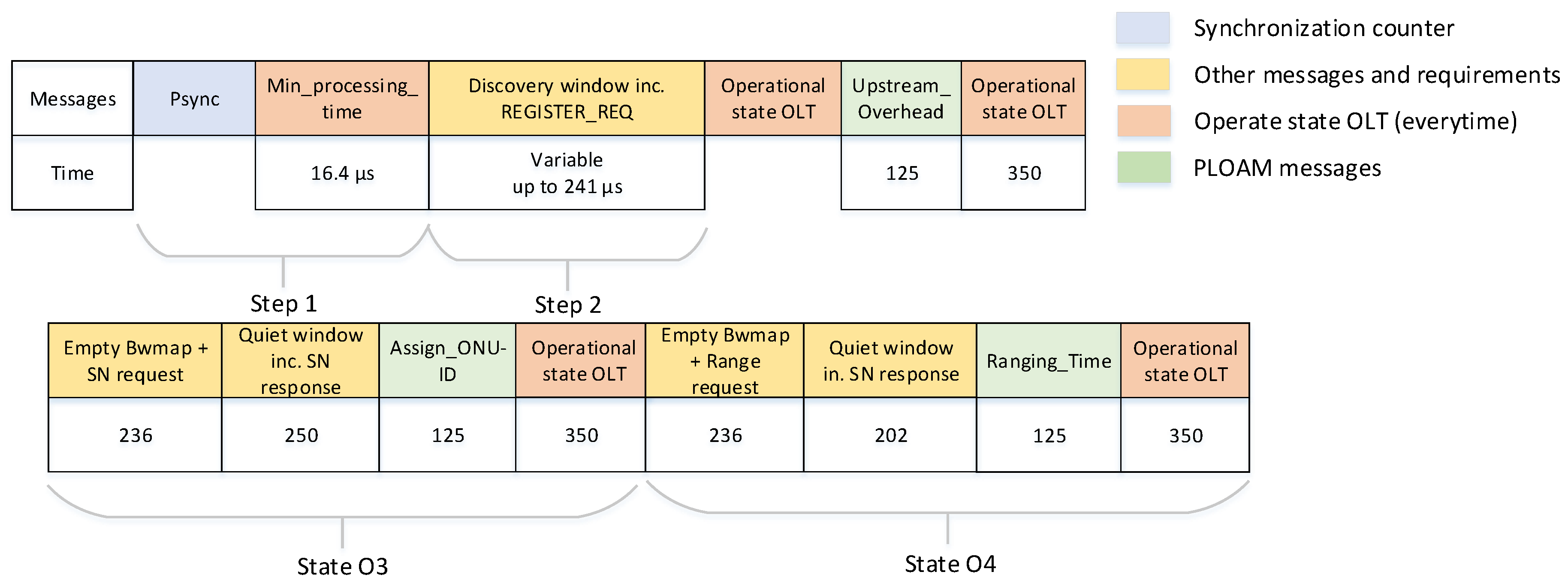
The presented results were based on the graph comparing the EPON and GPON with 32/64 units and a 20-km ODN length. The graphs are shown in Figure 7. As shown, the activation was several times faster using EPON instead of GPON. This was primarily because the selected frame length in EPON was only 409.6 ns, whereas in GPON, it was 125 μ s. The total activation time was much easier to evaluate for EPON than for GPON. Fewer messages were transmitted, and they were transmitted only once (GPON sends PLOAM messages three times); the minimum message processing time of the ONU was only 16.384 μ s, whereas for GPON, it was 750 μ s, and the equalization delay was not calculated during the simulation of EPON.
Figure 8 compares the activation process in XG-PON and NG-PON2. As mentioned previously, the activation process for XG-PON and NG-PON was based on GPON. However, there were some new states of substates. In other words, the PLOAM messages were almost identical. We did not consider a tuning process for changing the wavelength in the downstream or upstream because this process lies at the OLT side.
On the left side, Figure 9 compares the XG-PON and NG-PON2 standards for 128 connected units and a 20-km ODN length. The maximum connection time was several ms higher for NG-PON2 than for XG-PON. The increase in connection time can be explained by the higher number of transmitted messages and the occurrence of other synchronization processes. A maximum connection time of up to 420 ms can be observed. Nevertheless, it was necessary to consider the limitations of the simulation, e.g., the simulation did not consider any collisions that can normally occur in the real network (the time necessary for the activation process would be increased in such cases), etc. If we consider the higher split ratio (1:256), which is the maximum split ratio in XG-PON and NG-PON2, we observe an almost two-fold higher value for the activation process for a 20-km ODN length.
The final aim of this study was an optimization of the GPON standard. To preserve the physical essence, the calculations and the length of the messages cannot be altered. Optimization, therefore, serves to reduce the number of messages and the length of the OLT operating state, which is the time that OLT grants the ONU to process incoming messages. In GPON, all messages are transmitted three times. Hence, in theory, ONU should require less processing time. This time was set to 350 μ s. This is the sum of the duration of the sent message (125 μ s), the maximum propagation delay at 20 km, which was approximately 100 μ s, and the message processing time (125 μ s). The entire timing of the transmitted messages is indicated in Figure 10. A real GPON does not contain only 32 or 64 ONUs, and the current OLT supports up to 16 GPON ports per card. The total amount of these cards depends on the OLT chassis. We considered 16 GPON ports with 32 ONUs per port. The total amount of ONUs was 512 ONUs, which must be activated. The current activation process can activate all ONUs in ≈112 s or 74 s with our optimization, respectively. Furthermore, our solution did not require a new PLOAM message or TC layer changes.
Our optimization was based on current PLOAM messages and transmission convergence layer. There were no changes required. Visualization of the optimized GPON activation process is shown in Figure 11.

6. Conclusions

In this paper, we introduced an activation process for IEEE and ITU PONs. Although both networks are standards for passive optical networks, they use completely different encapsulation methods, frame durations and frame structures. Our results demonstrate that EPONs have a faster activation process (with a maximum split ratio 1:32) and that GPONs operate with a split ratio of up to 1:128. We chose the most commonly-used split ratio, 1:32 or 1:64, with 20 km, because a higher distance does not follow either standard. However, GPON supports a higher split ratio, and there are some issues with the timing and managing of the time slots for the upstream direction. The main reason for the shorter activation time is the different frame durations of 16.384 μ s and 750 μ s for EPONs and GPONs, respectively.
XG-PON and NG-PON2 use approximately the same activation process and provide almost identical results as do GPONs. However, NG-PON2 supports wavelength tuning during transmission, but it has to be initialized by the OLT. Due to this fact, it is not a part of the activation process. An activation time of 256 end units requires approximately 820 ms, but the OLT can operate with eight or more NG-PON2 ports, which leads to a multiplication of this time. During a blackout scenario, the last end user will have to wait multiples of minutes.
Our optimization accelerates the activation process for 64 ONUs from 220 ms to 145 ms. In a real network with 512 ONUs, the operator can save approximately 40 ms. Note that our solution does not require a new PLOAM message or TC layer changes.
In future work, we would like to implement a collision scheme into our simulation models.

Author Contributions

Conceptualization, T.H. and P.M. Methodology, T.H. and P.M. Software, V.O. and J.V. Validation, T.H. and P.M. Formal analysis, J.V. Investigation, T.H. Resources, P.M. Writing, original draft preparation, T.H., P.M., V.O. and J.V. Writing, review and editing, T.H. Visualization, V.O. Project administration, P.M. Funding acquisition, P.M. and T.H.

Funding

The presented research has been supported by projects of the Ministry of the Interior under Grant No. VI20172019072 registration, the National Sustainability Program under Grant No. LO1401, and E-infrastructure CESNET – modernization, registration number CZ.02.1.01/0.0/0.0/16_013/0001797.

Conflicts of Interest

The authors declare no conflict of interest.

Abbreviations

The following abbreviations are used in this manuscript:
ADSLAsymmetric digital subscriber line
Alloc-IDAllocation identifier
AMCCAuxiliary management and control channel
APONAsynchronous transfer mode passive optical network
BWmapBandwidth map
C-RANCloud-radio access network
CDRClock and data recovery
DBADynamic bandwidth allocation
DDSPONDistributed dynamic scheduling passive optical network
EPONEthernet passive optical network
EqDEqualization delay
FSFraming sublayer
GMIIGigabit media independent interface
GPONGigabit passive optical network
GTCGPON transmission convergence layer
HECHybrid error correction
IEEEInstitute of Electrical and Electronics Engineers
ISPInternet services provider
ITUInternational Telecommunication Union
LLIDLogical link identifier
MACMedium access control
MDIMedium-dependent interface
MLMMulti-longitudinal mode
MPCDMulti-point control protocol
NG-PON2Next Generation Passive Optical Network Stage 2
NRZNon-return-to-zero
LoFLoss of frame
LoSLoss of signal
ODNOptical distribution network
OLTOptical line termination
ONUOptical network unit
ONU-IDONU identifier
ORLOptical return loss
P2MPPoint to multipoint
PCBdPhysical control block downstream
PCSPhysical coding sublayer
PHYPhysical interface
PLOAMPhysical layer operations, administration and maintenance
PMAPhysical medium attachment
PMDPhysical medium dependent
PONPassive optical network
PSBdPhysical synchronization block downstream
PSyncPhysical synchronization
QoSQuality of service
RSReconciliation sublayer
RTDRound trip delay
SFCSuperframe counter
SLMSingle-longitudinal mode
TCTransmission convergence
TWDM-TCTime and wavelength division multiplexing transmission convergence
VHDLVery High Speed Integrated Circuit Hardware Description Language
WDMWavelength-division multiplexing
WiFiWireless fidelity
XG-PONNext generation passive optical network
XGTCXG-PON transmission convergence layer
WLCPWavelength channel protection

References

  1. Horvath, T.; Munster, P.; Vojtech, J.; Velc, R.; Oujezsky, V. Simultaneous transmission of accurate time, stable frequency, data, and sensor system over one fiber with ITU 100 GHz grid. Opt. Fiber Technol. 2018, 40, 139–143. [Google Scholar] [CrossRef]
  2. Vojtech, J.; Slapak, M.; Skoda, P.; Radil, J.; Havlis, O.; Altmann, M.; Munster, P.; Velc, R.; Kundrat, J.; Altmannova, L.; et al. Joint accurate time and stable frequency distribution infrastructure sharing fiber footprint with research network. Opt. Eng. 2017, 56, 027101. [Google Scholar] [CrossRef] [Green Version]
  3. Ansari, N.; Zhang, J. Media Access Control and Resource Allocation; Springer: New York, NY, USA, 2013; p. 103. ISBN 978-1-4614-3939-4. [Google Scholar]
  4. Ballance, J.W.; Rogers, P.H.; Halls, M.F. ATM Access through a Passive Optical Network. Electron. Lett. 1990, 26, 558–560. [Google Scholar] [CrossRef]
  5. Miyata, S.; Baba, K.I.; Yamaoka, K. Exact Mean Packet Delay for Delayed Report Messages Multipoint Control Protocol in EPON. J. Opt. Commun. Netw. 2018, 10, 209–219. [Google Scholar] [CrossRef]
  6. Chen, W.; Montuno, D.Y.; Felske, K. Enhanced EPON auto-discovery for fast network and service recovery. In Proceedings of the Canadian Conference on Electrical and Computer Engineering 2004 (IEEE Cat. No. 04CH37513), Niagara Falls, ON, Canada, 2–5 May 2004; pp. 1683–1687. [Google Scholar]
  7. Hajduczenia, M.; de Silva, H.J.A.; Monteiro, P.P. Extended GATE/REPORT MPCP DUs for EPONs. In Proceedings of the 11th IEEE Symposium on Computers and Communications (ISCC’06), Cagliari, Italy, 26–29 June 2006; pp. 1–6. [Google Scholar]
  8. Liem, A.T.; Hwang, I.-S.; Nikoukar, A.; Yang, C.-Z.; Ab-Rahman, M.S.; Lu, C.-H. P2P Live-Streaming Application-Aware Architecture for QoS Enhancement in the EPON. IEEE Syst. J. 2016, 12, 648–658. [Google Scholar] [CrossRef]
  9. Petridou, S.; Basagiannis, S.; Mamatas, L. Energy-Efficiency Analysis under QoS Constraints Using Formal Methods: A Study on EPONs. In Proceedings of the 2017 IEEE International Conference on Communications (ICC), Paris, France, 21–25 May 2017; pp. 1–6. [Google Scholar]
  10. Li, L.; Xin, S.T.; Duan, D.G. Research of DBA Schemes and QoS in PON System. In Proceedings of the 2016 2nd IEEE International Conference on Computer and Communications (ICCC), Chengdu, China, 14–17 October 2016; pp. 2148–2153. [Google Scholar]
  11. Mady, A.E.D.; Tonini, A. A VHDL Implementation of ONU Auto-discovery Process for EPON. In Proceedings of the ICNM: 2009 International Conference on Networking & Media Convergence, Cairo, Egypt, 24–25 March 2009; pp. 36–41. [Google Scholar]
  12. Garfias, P.; Gutierrez, L.; Sallent, S. Enhanced DBA to Provide QoS to Coexistent EPON and 10G-EPON Networks. J. Opt. Commun. Netw. 2012, 4, 978–988. [Google Scholar] [CrossRef]
  13. Pajcin, B.; Matavulj, P.; Radivojevic, M. MPCP adjusting for improving QoS in Green WDM EPON. In Proceedings of the 2016 International Workshop on Fiber Optics in Access Network (Foan), Lisbon, Portugal, 18–19 October 2016; pp. 1–6. [Google Scholar]
  14. Zhang, M.; Liu, X.F.; Song, C.; Zhang, H. Grouped LR-EPON with WDM-OFDM-TDM DBA Algorithm and Sleep-Based Energy-Efficient Mechanism. In Proceedings of the 2016 15th International Conference on Optical Communications and Networks (ICOCN), Hangzhou, China, 24–27 September 2016; pp. 1–3. [Google Scholar]
  15. Liu, C.P.; Wu, H.T.; Ke, K.W. Asymmetric Loading on the Energy Saving Scheme for EPON Networks. In Proceedings of the 2017 IEEE International Conference on Consumer Electronics—Taiwan (ICCE-TW), Taipei, Taiwan, 12–14 June 2017. [Google Scholar]
  16. Horvath, T.; Munster, P.; Jurcik, M.; Filka, M. Novel Algorithm in Activation Process of GPON Networks. J. Commun. Softw. Syst. 2015, 11, 204–209. [Google Scholar] [CrossRef]
  17. Horvath, T.; Munster, P.; Jurcik, M.; Koci, L.; Filka, M. Timing measurement and simulation of the activation process in gigabit passive optical networks. Opt. Appl. 2015, 45, 459–471. [Google Scholar] [CrossRef]
  18. Koci, L.; Horvath, T.; Munster, P.; Jurcik, M.; Filka, M. Transmission Convergence Layer in XG-PON. In Proceedings of the 2015 38th International Conference on Telecommunications and Signal Processing (TSP), Prague, Czech Republic, 9–11 July 2015; pp. 104–108. [Google Scholar]
  19. Luo, Y.Q.; Effenberger, F.; Gao, B. Transmission Convergence Layer Framing in XG-PON1. In Proceedings of the 2009 IEEE Sarnoff Symposium, Conference Proceedings, Princeton, NJ, USA, 30 March–1 April 2009; pp. 298–302. [Google Scholar]
  20. Eramo, V.; Listanti, M.; Lavacca, F.G.; Iovanna, P.; Bottari, G.; Ponzini, F. Trade-Off Between Power and Bandwidth Consumption in a Reconfigurable Xhaul Network Architecture. IEEE Access 2016, 4, 9053–9065. [Google Scholar] [CrossRef]
  21. Eramo, V.; Listanti, M.; Lavacca, F.; Iovanna, P. Dimensioning Models of Optical WDM Rings in Xhaul Access Architectures for the Transport of Ethernet/CPRI Traffic. Appl. Sci. 2018, 8, 612. [Google Scholar] [CrossRef]
  22. International Telecommunication Union. G.984.1: Gigabit-Capable Passive Optical Networks (GPON): General Characteristics. Available online: https://www.itu.int/rec/T-REC-G.984.1-200803-I (accessed on 18 September 2018).
  23. International Telecommunication Union. G.984.2: Gigabit-Capable Passive Optical Networks (G-PON): Physical Media Dependent (PMD) Layer Specification. Available online: https://www.itu.int/rec/T-REC-G.984.2-200303-I/en (accessed on 18 September 2018).
  24. IEEE Standard for Information Technology—Local and Metropolitan Area Networks—Specific Requirements—Part 3: CSMA/CD Access Method and Physical Layer Specifications Amendment 1: Physical Layer Specifications and Management Parameters for 10 Gb/s Passive Optical Networks; IEEE Std 802.3av-2009 (Amendment to IEEE Std 802.3-2008); IEEE: New York, NY, USA, 2009; pp. 1–227. [CrossRef]
  25. Widmer, A.X.; Franaszek, P.A. Transmission Code for High-Speed Fibre-Optic Data-Networks. Electron. Lett. 1983, 19, 202–203. [Google Scholar] [CrossRef]
  26. International Telecommunication Union. G.984.3: Gigabit-Capable Passive Optical Networks (G-PON): Transmission Convergence Layer Specification. Available online: https://www.itu.int/rec/T-REC-G.984.3-201401-I/en (accessed on 18 September 2018).
  27. International Telecommunication Union. G.987.3: 10-Gigabit-Capable Passive Optical Networks (XG-PON): Transmission Convergence (TC) Layer Specification. Available online: https://www.itu.int/rec/T-REC-G.987.3 (accessed on 18 September 2018).
  28. International Telecommunication Union. G.989.3: 40-Gigabit-Capable Passive Optical Networks (NG-PON2): Transmission Convergence Layer Specification. Available online: https://www.itu.int/rec/T-REC-G.989.3 (accessed on 18 September 2018).
  29. Kramer, G. Ethernet Passive Optical Networks (Professional Engineering), 1st ed.; McGraw-Hill Education: New York, NY, USA, 2005; 307p, ISBN 978-0071445627. [Google Scholar]
  30. Cui, Q.P.; Ye, T.; Lee, T.T.; Guo, W.; Hu, W.S. Stability and Delay Analysis of EPON Registration Protocol. IEEE Trans. Commun. 2014, 62, 2478–2493. [Google Scholar] [CrossRef] [Green Version]
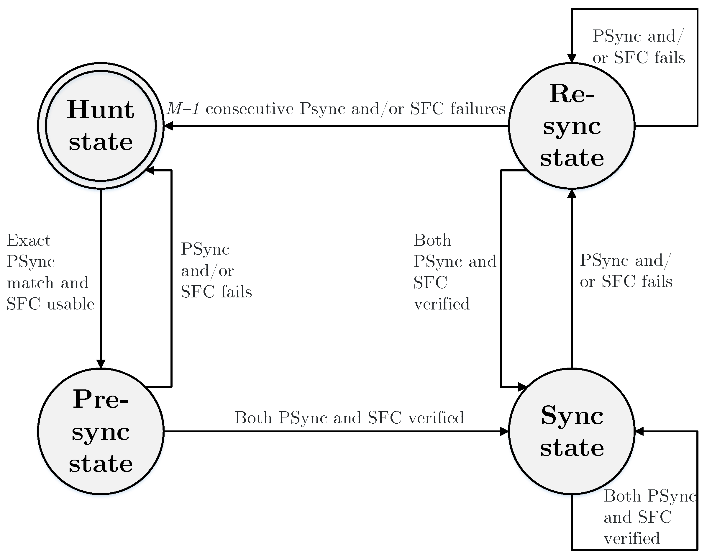
Figure 1. Synchronization state machine for XG-PON downstream [27].
Applsci 08 01934 g001
Figure 2. State diagram of ONU unit for NG-PON2 [28].
Applsci 08 01934 g002
Figure 3. Activation process in EPON networks.
Applsci 08 01934 g003
Figure 4. Visualization of the GPON activation.
Applsci 08 01934 g004
Figure 5. Visualization of the XGPON activation.
Applsci 08 01934 g005
Figure 6. Visualization of the NG-PON2 activation.
Applsci 08 01934 g006
Figure 7. Graph of activation time for EPON (left) and GPON (right) 32/64 units and 20-km ODN.
Applsci 08 01934 g007
Figure 8. Graph of activation time for XG-PON (left) and NG-PON2 (right) 32/64 units and 20-km ODN.
Applsci 08 01934 g008
Figure 9. Graph of activation time for XG-PON and NG-PON2 with a 1:128 split ratio and 20-km length of ODN (left) and XG-PON and NG-PON2 with a 1:256 split ratio and a 20-km length of ODN (right).
Applsci 08 01934 g009
Figure 10. Graph of activation time for GPON (left) and optimized GPON (right) 32/64 units and 20-km ODN.
Applsci 08 01934 g010
Figure 11. Visualization of the optimized GPON activation process.
Applsci 08 01934 g011
Table 1. Basic comparison of GPON with EPON.
ParametersGPONEPON (Type 2)
StandardITU-T G.984IEEE 802.3ah
Bitrate downstream1.244/2.488 Gbit/s1.25 Gbit/s
Bitrate upstream1.244/2.488 Gbit/s1.25 Gbit/s
λ for downstream1480–1500 nm1490 nm
λ for upstream1260–1360 nm1310 nm
Split ratio64 (up to 128)32
Network reach20 km20 km