1. Introduction
With the rapid development of new energy generation technologies such as photovoltaic power generation, wind power generation, et cetera, as well as user’s growing requirement of power quality and power supply reliability, power system has changed from the traditional centralized large power grid to the multi-area interconnected power system [
1]. The reliability, flexibility and economy of power grid can be greatly improved by the coordinated and optimal operation of regional interconnected power system. Moreover, it should not be ignored that the interconnection of regional power systems will increase the uncertainties and bring problems about the frequency stability in the power network [
1,
2,
3].
A high-quality power system requires the power frequency rate and voltage of system to be kept within a certain range around the set value. This requirement can be reached by adjusting the active power and reactive power of the system. The load frequency control (LFC) is an important part of the automatic power generation control (AGC) in power system and the function of the LFC is to ensure the stability of power system load frequency [
4,
5]. In other words, the LFC is used to keep the balance between the generating power and user load. Specific assignments of the LFC are as follows: (1) Make sure that the deviation of load frequency can be maintained at zero. (2) The switching power between tie-lines can return to the set value quickly under any load variation disturbance [
6]. The study of load frequency stability control in power system began around the 1970s [
7,
8]. In pace with the development of LFC, the control mode has developed from only considering the load frequency stability into combining the load frequency with the tie-line exchanged power together [
8,
9,
10]. The control object has also changed from a single generator to the whole power plant area, and from a single-area system to the multi-area interconnected power system [
10]. Many scholars have been looking for methods to improve the control effect of the LFC, such as applying neural network theory, adaptive control, fuzzy control, predictive control and other optimal control theories. The chaos optimization algorithm is used to adjust the multi-area load frequency control PID controller in [
11]. In [
12], it is proposed to combine the adaptive modified bat algorithm with the fuzzy logic (FL) to set the parameters of the proportional controller on line to improve the control effect of the LFC. The particle swarm optimization (PSO) algorithm is applied to adjust parameters of the proposed PI controller in [
13]. The uncertainty caused by the variation of governor and turbine parameters is considered in [
14], and an adaptive model predictive control (AMPC) method is applied to the LFC controller for multi-area power systems which can change the object model in MPC structure online. However, the research on LFC optimization is not only reflected in the improvement of controller and algorithm. In [
15], multiple controllable thyristors or synchronous series compensators are installed in multi-area power systems, improving the dynamic control effect of the LFC by the coordinated control of phase shifter.
The main contributions of this paper are as follows: (1) We propose a new diagram of four-area interconnected power system and establish the dynamic mathematical model of power system in each control area. (2) The HESS is introduced to provide the power flow in purpose of regulating the frequency and tie-line exchanged power of system. (3) We apply the generic mode control method in [
16] to realize the charging and discharging of the HESS. (4) We design the H
∞ robust controller based on the LMI and state-feedback method to calculate how much power the HESS should provide to the power system. Through the analysis and comparison of simulation results from PID control, it is identified that the H
∞ controller can improve the stability of power frequency under external load disturbance and the HESS can convert the output power demand signal from the H
∞ controller into the corresponding power flow effectively.
This paper is organized as follows: in
Section 2, a new topology diagram of four-area interconnected power system with the HESS is presented and concepts of the LFC and the HESS are introduced.
Section 3 presents a detailed mathematical model of
ith control area within the four-area interconnected power system in the form of state space equation. H
∞ state feedback controller is designed for power system with the HESS in the
ith control area in
Section 4, based on the mathematical model established in
Section 3. Further simulation verification and results analysis of the method proposed in this paper are presented in
Section 5. Finally, the conclusion is given in
Section 6.
2. Multi-Area Interconnected Power System with the HESS
Interconnected power system is usually composed of several control areas. Each area is connected to another by a tie-line for power exchange under normal operating conditions to overcome the mismatch between the generation and the demand [
17]. Under any load change disturbance, there are two control aims in the operation of interconnected power system model:
One objective is to make sure that the deviation of load frequency is zero or fluctuate in a certain really small range near zero.
Another objective is to ensure that the switching power of the tie line returns to the set value.
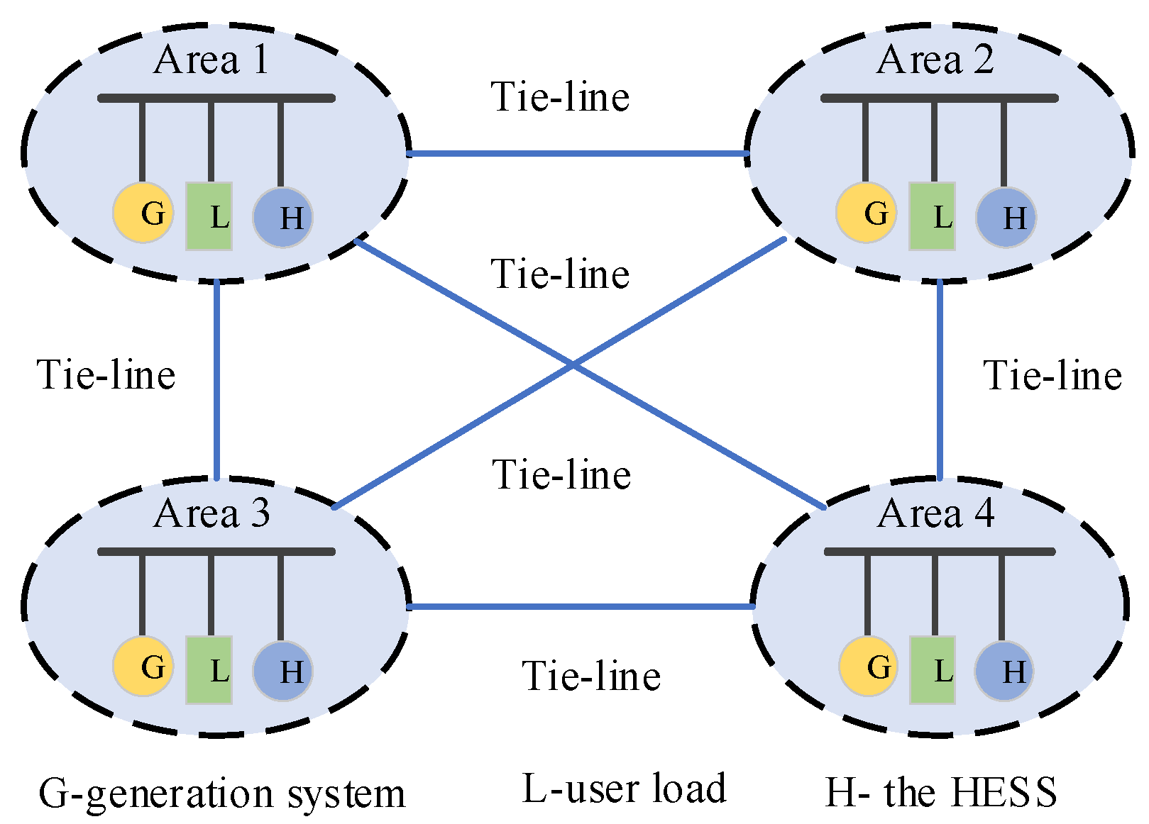
Taking the four-area interconnected power system as an example, a new topology diagram of interconnected power system with the HESS is presented in this paper which is shown in
Figure 1 [
6]. The regional power system consists of three parts: generation system, user load and the HESS. In
Figure 1, “G” represents the generation system, “L” indicates the user load and the “H” denotes the hybrid energy storage system (HESS).
2.1. Load Frequency Control
Power system is a complex nonlinear dynamic system, because the power system is always affected by the load disturbance which results in the load frequency fluctuation [
18]. In general, we use the method of near linearization to deal with the power system model. We usually adopt the linearization method near a certain working point to deal with the power system model [
19,
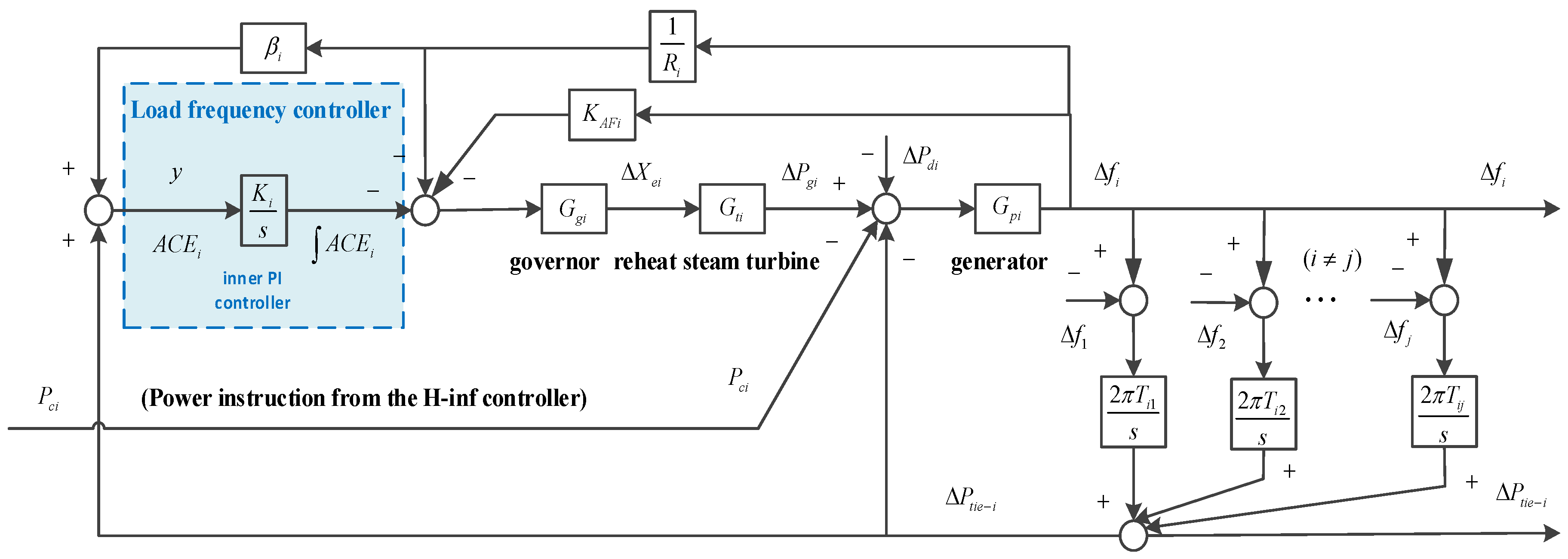
20]. A linear model is established to represent the dynamic model of system. The linearized model structure of system of
ith control area in the interconnected power system is shown in
Figure 2, which mainly includes the generator, the reheating turbine and the governor.
The linearized model of the governor is as follows:
The linearized model of the reheat steam turbine is shown as:
The linearized model of the generator is as bellow:
The physical implications of variables in the model of ith (i = 1,2,3,4) control area are as follows: , , , and , respectively, represent the time constant of governor, the reheating time constant, the time constant of steam turbine and the time constant of power system. indicates the incremental variation of governor valve position. is the increment of output thermal power from reheat unit. denotes the deviation of power exchange between tie-lines. represents the load disturbance. is the load frequency deviation of system. c is the reheating coefficient and is the gain of power system. represents the power synchronization coefficient of tie-line between the ith control area and the jth control area (). is the proportional negative feedback coefficient of the frequency deviation. denotes the frequency deviation constant that satisfies , where is the set value of frequency deviation and is the speed regulation gain.
To improve the power system with better dynamic performance, we should not only make sure that the frequency deviation (
) of the system tends to zero, but also ensure that the deviation of power exchange between tie lines (
) is close to zero under any load disturbance. Considering the two targets above, the concept of area control error (ACE) is proposed in the LFC. The expression of ACE in the
ith control area is formulated as (4):
In this paper, there is an internal PI controller in power system for frequency regulation which can be seen in
Figure 2. The controlled variable
is as follows:
where
represents the control coefficient of PI regulation in
ith control area.
Many works have been done to improve the control effect of the LFC and several novel control methods have been applied to the internal controller design in LFC. For example, the application of parameter self-adjusting algorithm to the PID controller [
11,
12] and the design of adaptive model predictive controller. In this paper, a hybrid energy storage system is introduced into traditional power system and an H
∞ robust state feedback controller is designed. The controller calculates the power supply in real time according to the variation of user load in system, and then the power control signal is transmitted to the HESS. The regulation of power in the system is realized by the effective charge and discharge of the HESS, which can ensure the stability of the load frequency.
2.2. Hybrid Energy Storage System
To guarantee the balance between the user power requirement and the active power generated by power grid, it is necessary to install the energy storage equipment with a certain capacity to adjust the power fluctuation of the power system. In the power system, the energy storage system is mainly used to calm down the fluctuating power of the system, reduce the sharp oscillation of system and cut down the peak and valley difference of the load power rate curve in purpose of enhancing the power quality [
21,
22,
23]. We introduce the HESS into the inter-connected power system. The HESS aims to stabilize the load frequency of the power grid and eliminate a series of negative effects caused by the fluctuating power.
HESS is a kind of energy storage equipment composed of super capacitor (SC) and battery (B). The HESS has been proved theoretically that the structure can give full play to the characteristics of these two kinds of energy storage equipment by Dougal et al. in 2002 [
24,
25]. The SC has the characteristics of high power density, short charge and discharge time, high reliability and long cycle life. It is suitable for situations require high power, frequent electric charge and discharge instead of the battery with low energy density [
22,
25]. Nevertheless, the combination of SCs and batteries can not only meet the qualification of high power density and high energy density, but also can reduce the rated capacity of batteries and prolong its service life. Currently, the HESS has been widely regarded as an effective way to calm down the grid power fluctuation due to its technical and economic advantages [
26,
27].
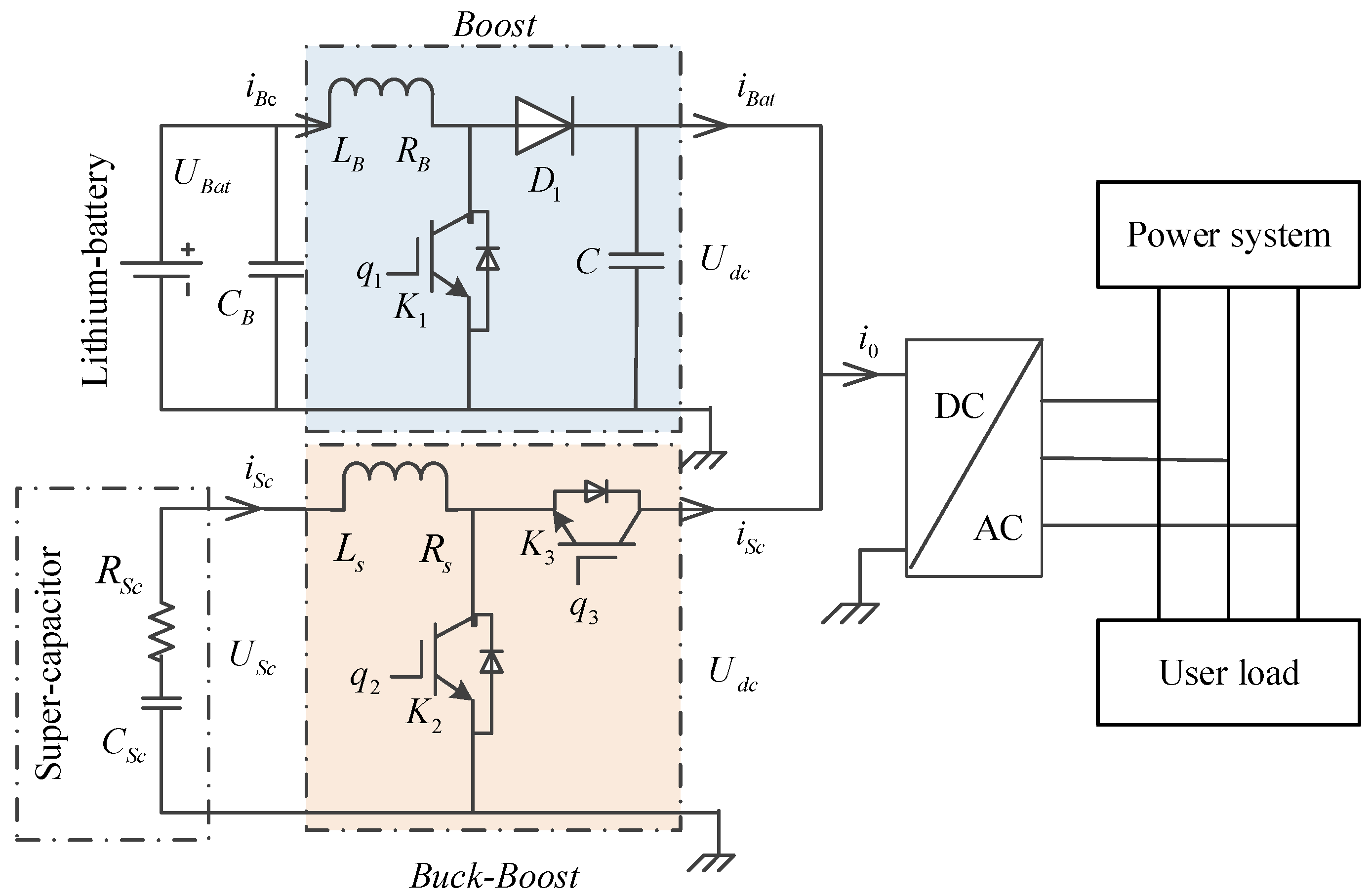
The hybrid energy storage system (HESS) can be mainly divided into two categories: the passive HESS and the active HESS. In this paper, we choose an active parallel HESS comprised of super capacitors and Lithium-ion batteries. The basic structure of HESS is shown in
Figure 3.
In
Figure 3, the battery is connected with a boost converter and the supercapacitor is connected with a bi-directional DC-DC converter (buck-boost) [
28]. Two converters share the same DC link which is connected to the power system through a DC-AC converter. As shown in
Figure 3, the Lithium-ion battery part is composed of a inductance with high frequency
, an IGBT (Insulated-Gate Bipolar Transistor)
, a diode
and an output filter capacitor
which plays a role in protecting the battery [
29].
is the voltage of the Lithium-ion battery.
is the inductor input current.
denotes the boost converter output current.
represents the voltage of DC bus. The super capacitor part consists of a high frequency inductance
and two IGBTs
and
;
and
represent the equivalent resistance and equivalent capacitance value of the super capacitor.
is the voltage of the SC.
is the inductor input current and it can be positive or negative.
is positive when the SC is in discharging mode. IGBT
,
and
respectively controlled by binary signal
,
and
. The PWM signals for Lithium-ion battery and super capacitor are generated according to the energy-management strategy [
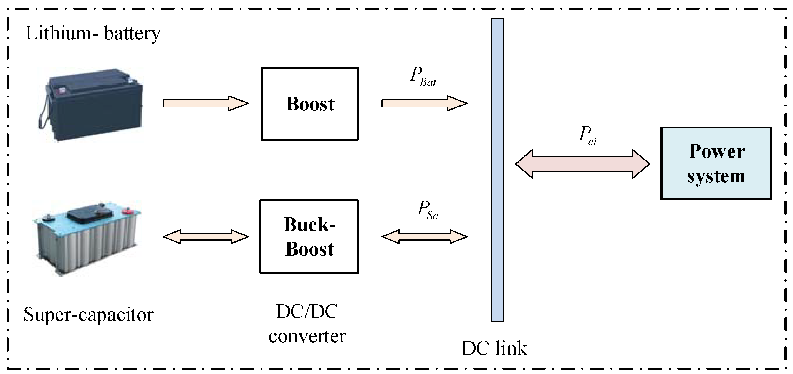
16]. The power exchange between the HESS and power system can be seen in
Figure 4.
represents the power requirement from power system corresponding to the output power instruction from the H
∞ state feedback controller designed in this paper.
and
are the power should be provided to power system by the battery and super-capacitor. Moreover,
is positive when the SC is in discharging mode and negative in charging mode. There are two working modes, namely, the voltage-reduction or charging mode and the boosting or discharge mode [
30]. The power instruction
and
converted the corresponding current instruction
and
by calculation [
16]. The HESS absorbs or emits corresponding power according to the difference value between the power generated by the power grid and the power required on the user side, thus the stabilization of frequency fluctuation power in power grid can be realized.
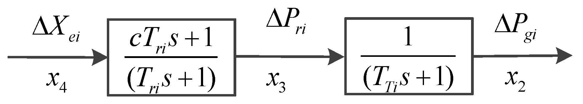
3. Mathematical Model of Power System with the HESS in the ith Control Area
State space description can effectively reveal and utilize the inner state information of the system. By this way, the complexity of mathematical representation will not be increased when the numbers of variables increase. In this paper, the mathematical model of
ith control area within the four-area interconnected power system is established in the form of state space equation. To facilitate modeling, the linear expression of the reheat steam turbine (Equation (2)) is decomposed as shown in
Figure 5. In
Figure 5,
denotes the output power increment of power generation,
is the output thermal power increment of reheat unit and
indicates the incremental variation of governor valve position.
Thinking about the
ith control area in a multi-area interconnected power system, define the output
, the input
, inner state-space vector
and the disturbance vector
. The detailed expressions are as follows and all variables in state-vector
are explained in
Section 2.1.
The state space model of power system in
ith control area can be established as follows:
where
,
,
and
are parameter matrices of system. Their expressions are as below:
4. H∞ State Feedback Controller Design for Power System with the HESS in the ith Control Area
Take the four-area interconnected power system as study object. The control block diagram designed for the
ith control area is shown in
Figure 6.
is a given power instruction calculated by the H
∞ controller to the HESS.
denotes the power flow provided to power system by the HESS.
is the output of power system in the
ith control area which denotes the area control error (ACE).
, … ,
(
i = 1, 2, 3, 4) present six inner state quantities of the
ith control area. The specific description and meaning of each state which have been given in
Section 2 and
Section 3.
Combining the mathematical model (Equation (6)) of power system in
ith control area with the control structure shown in
Figure 6, the closed-loop system model of the
ith control area can be expressed as follows:
where
represents the disturbance signal consisting of
and
, which, respectively, represent the load disturbance and the interregional interaction.
is an input signal of system which is generated by the HESS,
is an evaluation signal and
is the observed signal of system. In this paper, we choose
as the observed quantity.
is an identity matrix.
,
and
are coefficient matrices of the controlled object which are detailed described in
Section 3.
and
are both weighted coefficient matrices. It should be noticed that, if the selection of
or
is not appropriate, there will be a bad influence on the control performance of the system.
(
i,
j = 1, …, 6) and
are weighting coefficients greater than zero. The definition of evaluation signal
is as follows:
The controller coefficient matrix
is designed satisfying the stability condition of
. The matrix
in Equation (7) is required to be column full rank to make sure that the controller
is a real rational function matrix. The state feedback controller of power system in
ith control area is designed as follows:
Substituting Equation (9) into Equation (7), the corresponding expression can be obtained as follows:
Aiming at the problem about robust stability and disturbance suppression performance of control system, the key of state feedback controller design by using H
∞ control theory lies in: solving appropriate state feedback controller promising the closed-loop system is stable and the H
∞ norm of the closed-loop transfer function matrix is minimum or less than a given value. Let
be the transfer function from input
w to output
z. The goal of H
∞ design is guaranteeing the H
∞ norm of
to be less than
and it can be expressed as follows:
The following three kinds of H
∞ controller design problems can be differentiated according to the selection of
. If the state feedback controller
K(s) can guarantee the closed-loop transfer function of the control system to be internally stable and the value of
is minimum. That is,
and it is called H
∞ controller optimal design. If
satisfies the equation
based on satisfying the sufficient stability condition of
, then this kind of problem is H
∞ controller suboptimal design problem. If
exists, then the corresponding H
∞ controller standard design problem [
31,
32,
33].
Then, the following linear matrix inequality is established considering Equation (11) and standard design problem of H
∞ controller design:
If there exists a set of feasible solutions and can ensure the above inequality holds true, then is an H∞ state feedback controller of the system and the controller coefficient matrix is . The control coefficient matrix can be obtained by using the MATLAB LMI toolbox, feasp() or mincx() function to solve the linear matrix inequality in Equation (12).
5. Simulation and Result Analysis
Taking the four-area interconnected power system as research object in this paper and each control area can be distinguished by setting different values to various parameter variables. In the case of Control Area 1, the parameter settings are shown in
Table 1.
The electrical simulations of interconnected power system for four control areas area carried out through Matlab 2012a/Simulink in following three different cases:
Case 1: Traditional LFC, i.e., power system without the HESS.
Case 2: Power system with the HESS and external PID controller [
14,
34].
Case 3: Power system with the HESS and external H∞ robust state feedback controller.
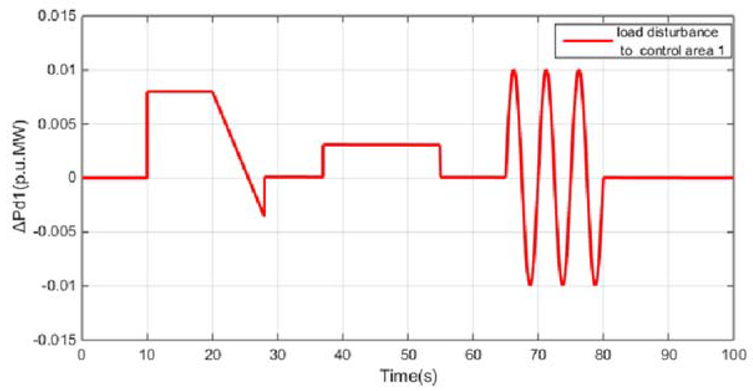
Set the simulation time to 100 s. To test the robust stability and the suppression ability of the control system under load disturbance, load interference is added to the power system in Control Area 1, as shown in
Figure 7, which consists of step signal, ramp signal and sinusoidal signal [
35]. It is worth pointing out that, when Area 1 is disturbed by load interference, the load frequency of power systems in the other three control areas will be affected through the tie-lines between each area.
Take the Area 1 as an example. In the process of H
∞ robust state feedback controller design, the weighting coefficients and performance indices are given as
Table 2. Combining
Section 4, the state feedback control coefficient matrix of Area 1 can be obtained by Matlab as
= [−10.8625, 25.5883 5.2364, −8.8031, −7.6875, −9.2341] and coefficient matrices for other three control areas can be easily obtained by using the method above.
For Case 3,
Figure 8 shows the control signal
,
,
,
for each control area from the H
∞ state feedback controller designed in this paper. These control signals denote the power instruction transmitted to the HESS from H
∞ controller. More attention should be paid to the magnitude order of the axis because they are different in each figure. It can be noticed that the orders of magnitude in
Figure 8b–d are really small, respectively,
,
and
.
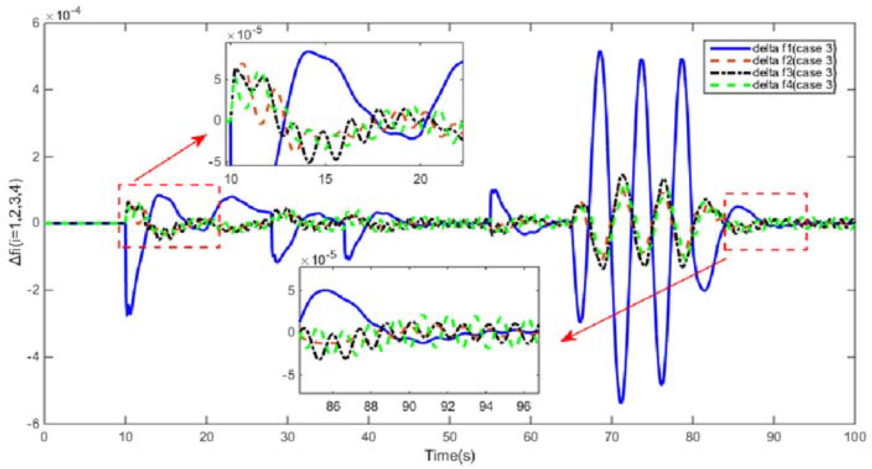
Figure 9 shows the load frequency deviation
of each power system under load disturbance in Case 3. When the load disturbance of
Figure 8 arises in Control Area 1, load frequencies of each power system will be subjected to varying degrees of influence. Under the condition of LFC with the HESS and external H
∞ robust state feedback controller, in
Figure 8 we can see that the load frequency
restores stability rapidly in seconds and
was guaranteed to be within ±0.0006 Hz since the maximum interference is almost 10 Kw. The result comparison of PID controller and H
∞ state-feedback controller is shown in
Figure 10 under the condition of LFC with the HESS.
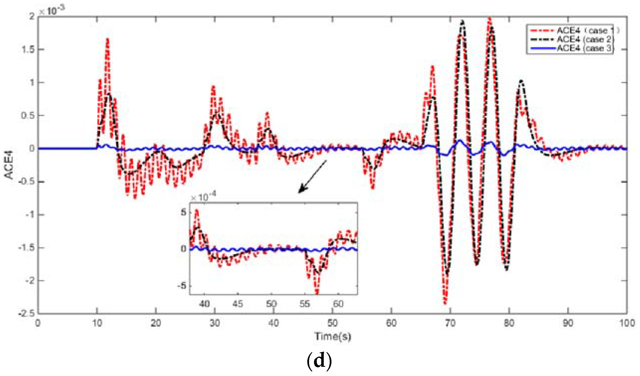
Figure 10 shows the control effect comparison of four areas in three different situations. The control effect is evaluated according to whether the value of the reference performance index
is close to zero. The expression of
is composed of terms
and
,
. The closer
is to zero, the better is the control effect.
Figure 10a–d, respectively, shows the simulation results of the Control Areas 1–4 in three different cases.
Comparing and analyzing the output waveform of the system, when the load disturbance occurs in Case 1, the
values of each region oscillate greatly and it takes more time to recover the stability near the zero value. Comparing PID control and H
∞ robust state feedback control, it can be clearly seen in
Figure 10 that H
∞ robust state feedback controller can effectively enhance the robustness and stability of the system in the condition of disturbance, keep the system output
fluctuating within the range of ±0.0006 Hz near zero and restore the system frequency stability within 10 s.
The design goal of this paper is to return the stability of the load frequency of the power system as quickly as possible in the event of external load disturbances, namely, make the value of area control error () stable at zero or within a minimum range near zero. Therefore, through the analysis of simulation results, it can be shown that the stability of power system and the control performance of the LFC can be improved effectively by introducing the HESS.


