Abstract
Several methods for corrosion monitoring of reinforced concrete structures (RCS) have been proposed in the last few decades. These systems may be used either in new, existing or repaired structures. The corrosion monitoring can be performed by different methodologies. These may or may not be destructive, use different degrees of complexity and cost, and provide information on the progression and kinetics of the corrosion phenomena. The destructive methods are limited to sampling. Therefore, these may not be representative of the whole structure, which is extremely important in RCS with large heterogeneities both in terms of materials used and in terms of the exposure environment. Within this context, non-destructive methods have been widely developed, which are intended to provide quick information about the entire structure. Ideally, these systems should be able to detect the corrosion state of the steel inside the concrete, the main causes of corrosion and the evolution of corrosion phenomena over time. This manuscript reviews and summarizes the actual state of the art and the main achievements in the field of electrochemical sensors based on non-destructive methods for corrosion monitoring of RCS in the last few years. The challenges and perspectives in this field will also be discussed.
1. Introduction
Concrete prepared with a suitable water/cement (w/c) ratio, well consolidated and properly cured offers excellent protection against corrosion to the reinforcing steel in concrete. When the steel is embedded in the concrete it is protected by a physical barrier and by a passivation film formed on the surface of the steel from the contact with aggressive species such as chloride ions (Cl−), carbon dioxide (CO2), sulfur dioxide (SO2), nitric oxides (NOx), or moisture. The passivation film formed on the reinforcing steel surface is due to the high alkalinity of the concrete (pH > 13.5). These high pH values are due to the presence of calcium hydroxide (Ca(OH)2) and potassium hydroxide (KOH). Furthermore, its high electrical resistivity restricts the rate of corrosion [1]. However, during the hydration and curing processes strain and tensions may be generated and promote the formation of cracks that may reduce the efficiency of the concrete barrier.
Generally, the degradation of concrete properties results from the combination of several internal and external factors. It is a complex process, widely determined by the physico-chemical properties of the concrete (internal factors) and by the environment that the concrete is exposed to (external factors). Furthermore, the physical barrier provided by the concrete is not perfect due to the porous structure of the concrete. The existence of imperfections during concreting and curing allow the ingress of aggressive species at the steel/concrete interface causing the rupture of the passivation film. The most common causes are the incorporation of Cl− and the reaction of atmospheric CO2 with the constituents of concrete and/or a combination of the two. The volume of the corrosion products is much higher than steel, approximately 4 to 6 times [2]. Therefore, the corrosion evolution in the reinforced concrete structures (RCS) produces expansion forces that, if they exceed the tensile strength of the concrete, initially lead to cracking or spalling followed of the detachment of the concrete [2]. The evolution of corrosion also leads to loss of adhesion between concrete and building steel, loss of ductility of steel and reduction of the section of steel rebar which may have implications on the stability of RCS [2].
Several methods for corrosion monitoring of RCS have been proposed in the last few decades. These systems may be used either in new, existing or repaired structures. These may be destructive, use different degrees of complexity and cost, and provide information on the progression and kinetics of the corrosion phenomena. The destructive methods are limited to sampling. Therefore, sampling may not be representative of the whole structure, which is extremely important in RCS with large heterogeneities both in terms of materials used and in terms of the exposure environment. Furthermore, in situations where the evolution of the corrosion over time is assessed it may not be advisable to use destructive methods. For example, for repair procedures it would not be suitable to remove a large quantity of samples required for assessment. Within this context, non-destructive methods have been widely developed, which are intended to provide quick information about the entire structure. These methods should be able to detect the corrosion state of the steel inside the concrete, the main causes of corrosion, as well as the evolution of the corrosion phenomena over time. The development of non-destructive electrochemical methods for the assessment of corrosion in RCS began in the 1970s with the measurement of corrosion potential. The measurement of corrosion rate, resistivity, galvanic current, oxygen limiting current and chloride content was followed in the early 1990s, and particularly in the last two decades. This manuscript reviews and summarizes the actual state of the art and the main achievements in the field of electrochemical sensors based on non-destructive methods for corrosion monitoring of RCS in the last few years. The challenges and perspectives in this field will also be discussed.
2. Corrosion of RCS
There are four conditions that must be met to initiate and maintain the corrosion process of RCS, namely: rupture of the passivation film and steel depassivation, which may be caused by carbonation of the concrete and/or Cl− ingress; O2 availability at the reinforcement interface in appreciable quantities; conductive medium or electrolyte between the anode reaction site and the cathode reaction site; existence of a conductor between the anode and cathode reaction sites. The electron flow measures the corrosion rate (icorr), which can be expressed as the mass loss per unit time and area, the thickness reduction per unit time or even as current density (current per unit area). For iron and steel, it is known that a corrosion rate of 1 µA cm−2 ≈ 12 µm year−1 ≈ 0.25 g m−2 day [2]. According to the quality of the concrete, the icorr depends on the following factors: moisture and resistivity of the concrete; temperature; oxygen and chloride ions availability and the pH of the solution that fills the pores of the concrete [1,2,3]. The corrosion mechanism of steel in concrete will not be discussed in detail since it can be easily found in several text books [2,3,4,5] and reviews [1,6,7] and it is not the aim of this review.
2.1. Carbonation-Induced Corrosion
Carbonation of the concrete can occur due to the chemical reaction of the alkaline components of the cement paste (e.g., NaOH, KOH, Ca(OH)2 and hydrated calcium silicate) with atmospheric CO2. As a consequence of carbonation, the pH of the interstitial solution in the pores decreases from values above 12.5 to values between 9 and 6. The final pH, after complete carbonation, depends on the following parameters: content of alkaline substances in the cement (Na2O, K2O), cement degree of hydration, moisture content, CO2 partial pressure and temperature. Besides CO2, other gases such as sulfur dioxide (SO2) or nitric oxides (NOx) may contribute to neutralization. The contribution of these gases is generally smaller because the SO2 or NOx content in air is, generally, much lower than the CO2 content. The carbonation of the concrete starts at the surface and can advance to a great depth reaching the reinforcement surface. The corrosion products of the steel in the carbonate concrete occupy a large volume when compared to the non-corroded metal [2], which causes pressure to be generated around the reinforcing steel resulting in the cracking of the concrete and subsequent detachment. The risk of corrosion due to the carbonation of the concrete depends on the depth of carbonation in relation to the cover thickness (dcarb/dcoat), see Table 1 [8].

Table 1.
Risk of corrosion due to carbonation of concrete according to Parrott [1].
2.2. Chloride Induced Corrosion
The corrosion of RCS induced by Cl− is the most frequent cause and has major costs and implications on the structural safety. Cl− may be introduced during the manufacturing phase of the concrete by contamination of the raw materials or may come from external sources; e.g., seawater, de-icing salts used in the cold season in some countries or hydrochloric acid from the decomposition of polyvinyl chloride in the event of fire in a building. Cl− can be found in concrete in two forms: free or bound. Among the bound chlorides, the strongly and weakly bound are distinguished. Strongly bound chlorides are chemically combined mainly in the form of calcium chloraluminates and calcium chloroferrites [9]. The weakly bound chlorides are adsorbed on the pore walls [9]. The hydrated compounds of the cement may be combined with the Cl− to a certain extension, regardless of whether their origin is external or whether they are introduced with the constituents. Of course, if the Cl− are introduced with the constituents the reaction will be favored. The free chlorides are dissolved in the interstitial solution and are the main players in the corrosion of RCS. These can destroy the passive film of the reinforcing steel by reducing the pH of the pore water. The solubility of Ca(OH)2 is reduced by increasing the moisture content, due to the hygroscopic properties of the salts present in the concrete (CaCl2, NaCl), and increasing the electrical conductivity of the concrete [2]. The bound chlorides can be converted to the free form, for example, by the carbonation of the concrete and thus constituting a potential reserve of Cl−. Recently, Geng et al. [10] reported an experimental study where the interaction between concrete carbonation and chloride attack was discussed. The authors reported that the carbonation of cement paste resulted in a release of bound chlorides, which was related to the decomposition of Friedel’s salt and with the decomposition of calcium-silicate-hydrate gel.
Chloride induced corrosion of reinforcement in concrete has been extensively studied in the last five decades under different conditions, mostly in relation to the chloride threshold value (CTV) or critical chloride content [11,12,13,14,15,16,17,18,19,20,21,22,23,24]. CTV may be expressed either as the total chloride content as a percentage by weight of cement/concrete, or as the molar ratio between [Cl−] and [OH−]. The [Cl−]/[OH−] ratio reflects the ratio of aggressive ions to inhibitive ions that lead to corrosion initiation in a solution environment and depend on the pH, temperature, moisture and surface finishing of the rebar [25].
The chloride-induced corrosion of RCS may be divided in two phases; corrosion initiation phase and propagation phase. The initiation phase is characterized by the penetration of the Cl− until the steel surface and depends on its rate, on the CTV and on the thickness of the concrete cover. The propagation phase initiates from the moment in which the conditions for the steel depassivation are reached until spalling and cracking of the concrete occurs [7].
2.3. Prediction of the Service Life of RCS
Corrosion modeling of reinforcing steel is one of the methods that has been gaining increasing interest in the last two decades [4,26,27,28,29,30,31,32,33,34,35,36,37,38,39,40,41]. Modeling the corrosion process will allow the assessment of the current state of the existing RCS, improve the stability and help to extend the service life of RCS. Most of the models developed are related to the penetration of Cl−, therefore with the initiation phase of corrosion [26,28,31,32,33,34].
The analysis of the behavior of RCS after corrosion initiation is important in order to efficiently select the maintenance and repair strategies. Furthermore, for an improved assessment of the conditions of the existing structures, the knowledge of the amount of reinforcing steel lost due to corrosion is crucial. The propagation period depends on the icorr, which in turn depends on the temperature, relative humidity, resistivity of the concrete and the presence of oxygen near the reinforcement. To improve the actual predictive models for the corrosion propagation period, data on icorr values measured in existing structures are necessary. Therefore, recording changes in icorr in real structures is an essential aspect to support the formulation and validation of a model for the propagation period. Therefore, it is crucial to develop reliable sensors to embed in existing structures that are able to detect its real state, enable the design of repair and maintenance strategies, and the prediction of the service life of RCS [38,41,42,43,44].
3. Reinforcement Corrosion Monitoring Techniques
There are several methods for corrosion monitoring of RCS [1,45,46,47,48,49,50,51,52,53,54], which, generally, are categorized as non-destructive methods (NDM) or destructive methods (DM). These methods allow the implementation of different methodologies with different degrees of complexity and cost, from which information on the progression and kinetics of corrosion phenomena can be obtained [55,56,57,58,59,60]. These methods can be used in new, existing or repaired structures. The situation becomes more complex in repaired structures since this type of structures involves the use of different repair products and interfaces. In the last few decades, the development of models to predict the service life of RCS has led to the need to quantify the icorr under different conditions of natural exposure. The measurement can be carried out in a destructive way, by means of the direct measurement of the reduction of the section of the rebar, or non-destructively through the use of instrumental methods. The destructive methods give us indication of the average speed of corrosion, the NDM allow to quantify the amount of metal that is corroded at a certain instant (e.g., instantaneous corrosion rate).
The recognition of the degradation of a structure is generally initiated by visual observation together with the collection of elements related to its history (type of structure, elements described in the project, year of execution, materials used, previous interventions, etc.). Visual inspection allows the assessment of corrosion damage on the surface of RCS. The appearance of the corroded area may provide valuable insight about the cause and extension of corrosion. Nevertheless, this method is extremely dependent on the inspector’s experience. Its effectiveness for detecting surface discontinuities due to steel corrosion and hidden corrosion is limited [57,61]. On the basis of this preliminary information, a sampling plan must be drawn up at representative sites of the structure such as characterizing sites of high risk of contamination or structural elements of major relevance. Concrete characterization tests are carried out for the collected samples. These results are compared with the project requirements and the adequacy of the type of concrete used, considering the environment that the RCS is exposed to. The carbonation depth of the RCS is determined with pH indicators (phenolphthalein) at different depths [5,8,62,63,64]. Considering the results obtained, in some areas, the concrete can be removed and direct observation of the reinforcement is performed. However, the DM are limited to sampling so they may not give an idea of the whole structure, which is extremely important in a RCS with large heterogeneities, both in terms of material and of exposure environment. Furthermore, in cases where it is necessary to assess the evolution of corrosion over time, such as following a repair intervention, it may not even be advisable to use DM. Within this context, NDM have been developed, in order to provide quick information about the entire structure. Ideally, these methods should be able to detect the corrosion state of the steel inside the concrete, the main causes of corrosion and the evolution of the corrosion phenomena over time.
In the 1970s, Elsener and Böhni started the development of non-destructive electrochemical methods, for the assessment of corrosion in RCS, with the measurement of corrosion potential [65,66]. According to Bertollini et al. [5] the measurement of galvanic current [67], corrosion rate, resistivity, reduction limit current of oxygen and chloride content was followed in the early 1990s. The application of the methods mentioned above requires the use of external sensors, placed on the surface of the concrete, or sensors embedded in the concrete. The use of external sensors allows measurements to be taken on the entire exterior surface of the concrete. However, it requires the intervention of an operator and, in some areas, the installation of means of access. These constraints turn the use of external sensors extremely expensive if an assessment over time is necessary. Furthermore, in painted structures, submerged or buried concrete areas, the use of external sensors requires the removal of the coating, to expose the concrete, which may affect the results. The use of sensors embedded in the concrete allows the use of automatic data acquisition systems, which enable the collection of information over large periods of time without accessing the structure. Embedded sensors can also collect valuable information in areas that are difficult to reach. Nevertheless, they have some disadvantages, such as providing more limited sampling information and the fact that the sensors have to be installed during construction or after repair works.
The first applications of sensors embedded in RCS occurred in the late 1970s with the introduction of reference electrodes to control corrosion potential in cathodic protection [65,66]. In the early 1990s, a sensor based on the measurement of the galvanic current in macro cells was proposed by Schiessl and Raupach [67]. In the last two decades’ sensors were developed for measuring the resistivity of the concrete [2,68,69], icorr [57,70], reduction limit current of oxygen [71,72] and chloride content [47,73,74,75,76,77]. There are several commercial systems that allow the simultaneous measurements of all or some of the abovementioned parameters [78]. These measurements can be performed from inside or outside of the RCS. Nevertheless, these systems are usually high in cost and are used mainly in developed countries [78]. In 2009, an integrated and cost-effective embeddable sensor to monitor the corrosion state of RCS was proposed [78]. The sensor measures the OCP and icorr of reinforcement steel, the resistivity, the availability of O2, the Cl− concentration in concrete, and the temperature inside the structure. The integrated system consists of different electrodes embedded in concrete together with a software system to acquire and analyze the data [78]. The efficiency of the embedded sensors depends on the selection of suitable areas and the type of parameters that are monitored. The selected areas must be representative of the environmental exposure that the structures are subjected to and, should be the ones with the highest probability of corrosion (e.g., areas of higher condensation or water stagnation; tidal and splashes zones in maritime structures). Moreover, the specific aspects of structural design or construction practices (e.g., high-density areas of reinforcement; corners; concreting and expansion joints) must also be taken into account.
3.1. Corrosion Assessment with Electrochemical Sensors
Several publications using electrochemical embedded sensors to monitor corrosion of RCS [46,73,78,79,80,81,82,83,84,85,86,87,88,89,90] including sensors with wireless communication of data [51,91,92,93,94,95] have been found. In 2009, Martínez and Andrade [88], published a paper where several examples of recorded data for corrosion potential, electrical resistance and corrosion rates were presented. The three case studies discussed showed that corrosion monitoring is achievable using different sensors and methods. The authors concluded that due to the variation of icorr found in RCS in natural exposure, a methodology to determine representative values of the icorr in order to assess with accuracy the service life of a RCS must be established [88]. Later, in 2013, Raupach et al. published a paper entitled “Condition survey with embedded sensors regarding reinforcement corrosion” [96]. The authors discussed the different types of sensor systems available based on different methods, including electrochemical. The main conclusion from this study was that the experience with monitoring systems has increased significantly [96]. In the same year Xu et al. [97] published a manuscript proposing a fast weak polarization method to test the corrosion state of reinforcements based on electrochemical polarization dynamics. Additionally, the authors developed a new corrosion sensor to monitor the corrosion state of concrete cover based on the proposed method. The authors concluded that the corrosion sensor effectively monitored the chloride penetration into concrete with insignificant influence of the relative humidity in the concrete [97].
Corrosion of new and existing RCS can be evaluated by different methods. The most important are listed below:
- Open circuit potential (OCP);
- Surface potential;
- Concrete resistivity (ρ);
- Polarization resistance (Rp);
- Noise analysis;
- Galvanic current (igal).
Most of the sensors found in the literature were developed to be installed in structures during the construction phase. The installation of a corrosion monitoring system using embedded sensors should not be seen as a generic procedure, to be applied to all structures. Instead, it is of particular interest to install these systems in structures located in particularly aggressive environments; in structural elements that are difficult to access; in structures where damage has already been detected; or structures that have been repaired and is of interest to follow the performance of the repair [3]. The selection of parameters to be assessed (e.g., temperature, icorr, pH, ρ, Cl−) as well as the type of instrumentation to be used may be different depending on whether the structure is under construction, already built, or in the process of being repaired. In a corrosion monitoring system, the parameters associated with the electrochemical behavior of steel or the evolution of corrosive conditions in the concrete should be followed. Temperature is an important parameter since all the chemical and electrochemical processes are thermally activated. Therefore, the corrosion of the reinforcement also depends on the temperature [84,98,99,100,101,102,103,104]. The knowledge gained in the last few decades has led to the development of sensors that are able to monitor different parameters simultaneously. For example, Yu and Caseres developed a sensor that monitors the concrete ρ, pH, chloride content, and microcell corrosion current [105]. The authors showed that the sensor, when in contact with paste, exhibited good sensitivity and reliability over the year of monitoring.
Ideally, embedded sensors must be stable in an alkaline environment, insensitive to chemical and thermal variations of concrete, weather tolerant and have the ability to allow the passage of small currents with a minimum of polarization and hysteresis effects. Furthermore, embedded sensors should provide long-term performance, information about the coating over time and the surface condition of the reinforcement (e.g., active or passive) and be of low cost. Regarding the state of the steel, the variation of the active state to the passive is of great importance and, once the corrosion has begun, the corrosion rate and its variation over time present higher risks. It is necessary to take into consideration the processing and presentation of the data together with the durability of the sensor itself. Nowadays, embedded sensors are used to measure the following parameters: chloride content [75,78,86,95], pH [106,107], moisture [108,109], icorr [46,73,80,81,88], temperature [93,108,110], potential [89,91], ρ [43,111,112,113], oxygen transport [72,78] and igal [82,90].
3.1.1. Open circuit Potential (OCP)
In RCS the concrete acts as an electrolyte and the steel develops a potential dependent on the characteristics of the surrounding concrete. Open circuit potential (OCP) is basically the measurement of the potential (in V or mV) in relation to a reference electrode [61,113,114,115,116]. A schematic representation for OCP measurements is shown in Figure 1. Examples of reference electrodes are saturated calomel (SCE), copper/copper sulfate (CSE), silver/silver chloride or even activated titanium [80]. This method is often controversial in terms of interpretation since the OCP measurements depend on the conditions of the RCS (e.g., moisture levels and Cl− amount) that may affect the readings leading to inaccurate results [61,116]. The information extracted from OCP indicates either a low or high probability of corrosion occurrence but it does not provide any information on the corrosion rate [84].
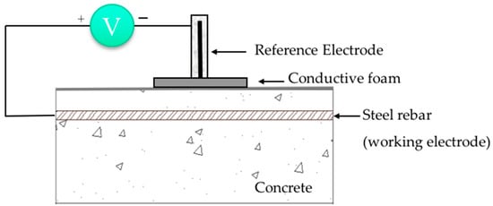
Figure 1.
Schematic representation of OCP measurements (reproduced and adapted from [50,73,116]).
According to ASTM C876-15 [117], the probability of steel corrosion, considering the OCP values, is shown in Table 2 [50]. If the steel potential in the concrete is lower than −276 mV vs. SCE there is a 90% chance of corrosion. The construction of corrosion potential maps according to ASTM C876-15 is the most applied electrochemical technique in the corrosion risk assessment of RCS. However, it is generally accepted that OCP should always be complemented with other measurements.
Table 2.
Risk of corrosion according to OCP values [50,117].
Several embeddable solid reference sensors in concrete for OCP monitoring have been developed [71,118,119,120,121,122,123,124]. Saturated calomel electrodes (SCE) and saturated copper sulfate electrodes, due to their compatibility and ease of use, are used for laboratory studies in alkaline environments—simulated concrete pore solutions (SCPS). Liquid based SCE are not suitable for embeddable sensors and their use is therefore restricted to laboratory environments [79]. Ag/AgCl reference electrodes are generally used in RCS to measure the rebar corrosion potential [79] or to determine the chloride content in SCPS [73,120,121,122,123,124,125,126]. Some reported that Ag/AgCl reference electrodes embedded in mortar specimens are stable only for short periods [127] while others found good long-term stability [128]. Solid type manganese dioxide (Mn/MnO2) reference electrodes appear to be more stable and reliable in RCS. Karthik et al. [79] showed that the half-cell potential of embedded Mn/MnO2 sensor in concrete was consistent with a good stability for an exposure period of 24 months.
OCP measurement is a very simple and useful technique and the construction of potential mapping, according to ASTM C876-15, allows identification of anodic and cathodic sites in RCS. Nevertheless, it should be kept in mind that OCP values provide only probabilistic information on the occurrence of corrosion.
3.1.2. Concrete resistivity (ρ)
Resistivity is an intrinsic property dependent on the ability of the concrete to carry electrical current [129]. Two different techniques, namely AC and DC, can be used for the determination of electrical resistivity [130]. These measurements apply both to external probes and to probes embedded in concrete. It has been used, indirectly, to assess concrete properties such as ionic diffusion of chloride ions and degree of saturation. It is a parameter strongly dependent on the quality of the concrete and the exposure conditions, such as relative humidity and temperature, which affect the degree of saturation of the concrete and therefore the ρ values.
Several authors have correlated the risk of corrosion occur and ρ [43,46,50,57,111,112,113,130,131,132,133,134,135]. ρ measurement is a useful and additional measure in identifying problems related to concrete corrosion and in assessing the quality of concrete. However, these measurements should never be performed in isolation. The ρ assesses the corrosion risk of steel reinforcement in concrete considering the relation between the ρ and the icorr of steel reinforcement [69,132,136]. According to some authors [137,138], the ρ is inversely proportional to the corrosion rate of steel reinforcement in concrete. Others stated that the under dry conditions the corrosion rate is mainly controlled by the ρ [43]. In 2007, Scott et al. [139] found that the icorr of steel reinforcement in concrete is essentially affected by the oxygen content in the concrete and by the thickness of concrete cover when the ρ is low. Nevertheless, the authors also showed that the icorr of steel reinforcement is predominantly affected by the ρ when concrete resistivity is high. Later, in 2014 Yu et al. [140], found that when the limit current density is high, the corrosion process of the steel reinforcement in concrete is under the resistance control and the corrosion rate generally decreases with the increase of ρ. Table 3 shows the risk of corrosion occur according to the resistivity values.
Table 3.
Risk of corrosion according to the concrete resistivity values (ρ) [50,132].
ρ values do not indicate if the steel in concrete is in passive or active state of corrosion. Instead, they provide additional information, such as indicating where in RCS the risk of corrosion is higher [130].
3.1.3. Polarization Resistance (Rp)
Polarization resistance (Rp) is a well-known, simple and non-intrusive method that allows the determination of the corrosion rate [50,81,84,141,142,143,144,145]. Rp can be determined by several electrochemical techniques. However, when applied to RCS, specific characteristics should be taken into account due to the high electrical resistance of the electrolyte (concrete).
The most common techniques used for Rp measurements, to assess the icorr of steel in RCS, were galvanostatic [3,5,70,146,147,148,149], potentiostatic pulses [17,136,150,151], cyclic voltammetry (conducted at very low scan rates) [151,152,153,154,155,156,157,158,159], and electrochemical impedance spectroscopy (EIS) [81,160,161,162,163,164,165,166]. The method proposed by Stern and Geary in 1957 is based on the observation of the linearity of the polarization curve together with the corrosion potential. A small potential perturbation (typically 10–20 mV or even 30 mV) is applied to the reinforcing steel (working electrode) and the resulting current is measured. The potential perturbation can be followed potentiostatically by the variation of the known potential (overpotential—ΔE) expressed with respect to the corrosion potential (overpotential (ΔE) = Eappl − Ecorr), and the monitoring of current decay (ΔI) during a certain period of time. Alternatively, this measurement can be carried out galvanostatically by applying a small fixed current value (ΔI) to the reinforcing steel, and monitoring the potential variation (overpotential—ΔE) for a certain period of time. In each case, the conditions are always selected considering that the ΔE falls within the Stern-Geary linear range of 10–30 mV. The Rp is defined as [142]:
The conversion of Rp to icorr, given by the Stern-Geary equation [145], involves the determination of the active corroding area as well as the compensation of the ohmic drop:
where B is a constant that depends on the Tafel slopes of the anodic (βa) and cathodic processes (βc):
Extensive experimental work has been performed in steel embedded in concrete in order to establish B values to be used in Stern’s equation according each corrosion situation [81,156,157,167,168]. The constant B, in the case of steel in concrete, ranges between 0.026 V (steel in the active state) and 0.052 V (steel in the passive state) [169]. Table 4 shows the construction steel conditions as a function of the values of icorr in RCS measured in situ and in laboratory.
Table 4.
Construction steel conditions as a function of the values of icorr in RCS measured in laboratory and in situ [46,136,178,179].
The icorr can be converted to corrosion rate (Vcorr) expressed in mm year−1, using Faraday’s law. Vcorr, represents the volumetric loss of metal by unit of area and unit of time and may be expressed in mm year−1 using Faraday’s law and the density of the metal. For the steel 1 µA cm−2 is equivalent to a corrosion rate of 1.16 × 10⁻¹ mm year−1 for uniform attack (Equation (4)) [130].
Vcorr (mm year−1) = 0.116 icorr (µA cm−2)
Gonzales et al. reported in 1985 [151] that the measured Rp must be accurate to avoid under- or overestimated icorr. Theoretically, DC methods such as cyclic voltammetry, potentiostatic transients, galvanostatic transients and AC methods such as EIS will all conduct to the same value of Rp when the appropriate frequencies, times and scan rates are used. In 1995, Sagués et al. [170] and Feliu et al. [171] reported that the Rp measurements should be performed under steady state conditions, otherwise large disparities can be found between the Rp values determined from DC and AC techniques. Feliu et al. stated that to obtain identical accuracy in Rp measurements, longer times are required in the frequency domain rather than in the time domain. Later in 2000, Lu and Peiyu [172] developed an algorithm (based on Fourier-transform) to measure the data of galvanostatic pulse method from the time domain into the frequency domain. The Rp and ohmic resistance were determined in the time domain and the impedance spectrum and disperse parameter were obtained in the frequency domain to characterize the corrosion status of reinforcement in concrete. Three years later Birbilis et al. [173] published an approach for the analysis of galvanostatically induced transients. The proposed approach allowed the determination of values for the parameters related to corrosion of steel reinforcement such as the concrete resistance, Rp, interfacial capacitance among others. In 2012 Christodoulou et al. [174] studied a simplified method for the application of transient analysis to in situ RCS. The authors concluded at low icorr values the transient response analysis seemed to provide more accurate data than the information obtained from polarization resistance analysis possible due to the use of smaller perturbation and the removal of the concrete resistance.
One of the major limitations to the use of this type of measure is that local penetration velocities, in the case of chloride-induced corrosion (pitting), are underestimated. The studies conducted for pitting corrosion, have shown that the Rp measurements lead to corrosion rate values 5 to 10 times lower than those obtained from direct measurements of rebar cross section [149,175].
Some constraints are present when measuring Rp on real structures. For instance, the area of the working electrode (rebar network), on a real structure, is much higher than that of the counter electrode on the concrete surface. Therefore, the electrical signal is lost when the distance from the counter electrode increases [2,74,84,149]. In these conditions the Rp values are linked to rebar surface area, which is unknown. Therefore, the measured values cannot be converted easily into the corrosion rate through the Stern-Geary equation. To overcome these limitations, Feliu et al. [176] have proposed a galvanostatic method for on-site Rp measurements. The authors introduced the concept of an external counter electrode (guard ring) for signal confinement. Another alternative is the use of electrochemical sensors in critical positions in the structure. However, in this case the working electrode area embedded in the concrete must be known. The use of this type of sensors will lead to crucial and detailed information. Furthermore, the information extracted allows modeling the service life of RCS and the acquisition of information from areas in structures with difficult access.
In 1997, Videm and Myrdal [177] compared several methods to assess the corrosion of RCS. The methods studied included manual potential mapping, automatic measurements of corrosion potential with embedded reference electrodes, linear polarization resistance measurements with cut reinforcement bars, analysis of the shape of galvanostatic charging curves, and linear polarization resistance measurements of the reinforcement with a commercial instrument containing a guard ring. Commercial reference electrodes were embedded in the concrete and a stainless steel rebar was used as a counter electrode. The results showed that the icorr determined with the guard ring did not agree with the results based on potential mapping or visual inspection. Later in 1999, Proverbio [178] carried out galvanostatic measurements in bridges using sections of steel construction as reference and working electrodes. Proverbio concluded that, the Rp measurements provided information that allows assessment of the corrosion process in RCS. However, the author also reported a wide dispersion in the Rp results, which makes its interpretation very challenging.
Potentiodynamic Method
The application of a small amplitude potentiodynamic scan, is one of the preferred methods used to obtain a reliable measurement of Rp in laboratory studies when the scan rate is slow [180,181]. Potentiostats with automatic compensation of ohmic drop are used. Amplitudes during measurement may range from 10 mV to 30 mV.
Potentiostatic Method
This method estimates Rp values from the application of small anodic potential pulses starting from the OCP, usually +10 mV. The value of the current that is generated is recorded for a certain time period. A schematic representation of the transient obtained in laboratory experiments after the application of a potential pulse of +10 mV is shown in Figure 2.
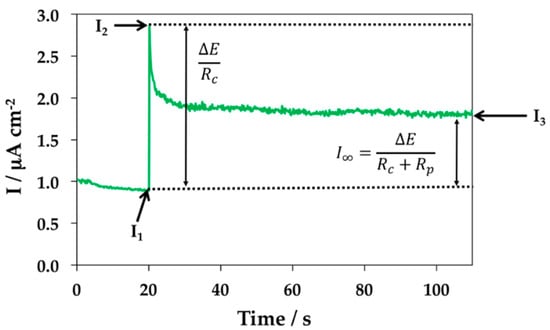
Figure 2.
Schematic representation of the transient obtained after the application of a potentiostatic pulse of +10 mV [182].
Rp sensors have been applied to new and existing structures [80,182]. In the case of existing structures, the sensors have to be fixed after concreting [80,182]. The electrolytic contact between the original concrete and the sensors is much more difficult to establish in a non–intrusive way and a few systems have been proposed [35,78,80,152,182,183]. Sensors are generally fixed inside holes. The electrolytic contact between the original concrete and the sensor is established by pressing the sensor against the concrete or by using sealing materials. Pereira et al. in 2008 [80,182], proposed three different embedded sensors for corrosion rate measurement, which were designed to be applied to existing RCS. The sensors were used to assess the effect of two surface treatments and a corrosion inhibitor on the control of steel reinforcement corrosion.
The measurements were performed using a three-electrode system (Figure 3 and Figure 4). Stainless steel electrode of 12 mm diameter was used as counter electrode; a steel electrode of construction (8 mm in diameter) was used as working electrode, with an average length of 10 and 9 mm, respectively, spaced 8 mm apart. As reference electrode Ti/TiO2 was used (Figure 3) [80,82].
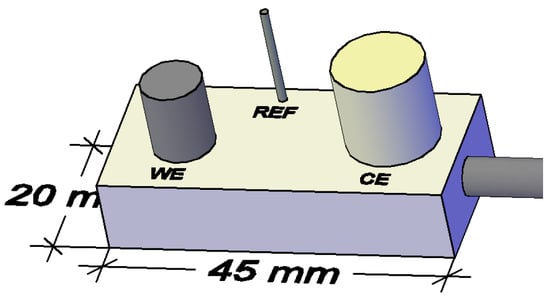
Figure 3.
Schematic representation of the Rp sensor (WE—working electrode, CE—counter electrode and REF—reference electrode). Reprinted with permission from Sensors MDPI [82].
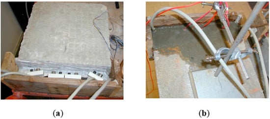
Figure 4.
(a) Fixing the Rp sensors Figure and (b) Filling with mortar [182].
The determination of Rp using this method is obtained from the following expression:
where: Rp—Polarization resistance (Ω cm2); ΔE—Potentiostatic pulse applied (V); S—area of the working electrode (cm2); I1—Current intensity measured at time t, immediately before the application of the potential pulse (A); I2—Current intensity value measured at time t at which the potential pulse (A) is applied; I3—Current intensity measured at the baseline reached at the end of the experiment (A).
Figure 5 shows the sensors attached in two different ways. In type M the sensors were covered with a porous mortar and in type T the sensors were covered with original concrete.
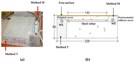
Figure 5.
(a) Picture of the methodologies used to fix the sensors. (b) Schematic of the specimens instrumented with the sensors under study. The methodologies used to fix the sensors are presented as well as the reinforcement and the working electrode (WE) of the sensors [182].
A third sensor using a non-intrusive method was proposed. In this method the working electrode is constituted by a section of rebar surrounded by the original concrete (Figure 6 and Figure 7). As reference electrode Ti/TiO2 sensor was used and as counter electrode (CE) a stainless steel rod was used (Figure 6).
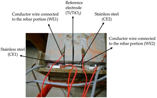
Figure 6.
Picture of two Rp sensors using a non-intrusive method [182].
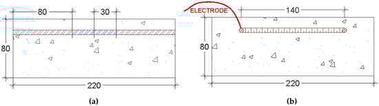
Figure 7.
(a) Schematic representation of the measures used to section the rebar and the lengths considered. (b) Schematic representation of the working electrode [182].
The authors concluded that the Rp embedded sensors are promising tools to assess the icorr of steel in existing concrete contaminated with chlorides. The methodology based on the use of sections of rebar, surrounded by the original concrete, as working electrode, for icorr measurements, should be preceded of meticulous assessment since, due to the heterogeneity of concrete, different corrosion states may be present [80,182].
Galvanostatic Method
The galvanostatic method is the application of a current pulse, from 10 μA to 20 μA, with duration between 8–10 s. It is a fast and non-destructive technique that provides information about the steel condition as well as information about concrete resistivity.
When a pre-selected constant current (Iapp) is applied to the system, the potential increases and the polarization of the steel occurs. Assuming that the system is described by a Randles circuit, the potential of the rebar V(t) at a given time (t) can be expressed by:
where: Rp is the charge transfer resistance at the surface of the steel rebar which is equivalent to the polarization resistance [183], Cdl is the double layer capacitance at the surface of the steel rebar and Rc is the ohmic resistance of the concrete between the surface electrode and the steel rebar.
By adjusting the function to the experimental results, following the procedure described by Elsener et al. [184] it is possible to obtain the values of Rp and Rc. After an equilibration time the transient response reaches a steady-state potential (Vmax), where:
loge (Vmax − Vt) = loge (I Rp) − (t/(RpCdl))
Plotting loge (Vmax − Vt) vs. t gives a linear graph with a slope equal to 1/RpCdl and intercepts at loge(IRp). The icorr can be obtained from Stern-Geary equation (Equation (4)).
In the last two decades this method has been widely studied [146,172,173,185,186,187,188,189] and is the basis of the development of commercial equipment with external probes for corrosion rate measurement [190,191].
Electrochemical Impedance Spectroscopy (EIS)
EIS measurements have been used as a non-destructive technique since the 80’s in the study of steel corrosion in concrete [81,192,193]. This technique provides information about several parameters, such as bulk concrete properties, the presence of films on the surface and interfacial corrosion and mass-transfer phenomena. The most used frequencies are between 100 kHz and 1 MHz, which obtain information on the resistivity of the concrete [194], transfer of charge, and diffusion phenomena [81,160,161,162,193,195,196,197,198,199,200]. Frequencies between 20 kHz to about 100 MHz have been used in the study of the dielectric behavior of concrete [197,201].
EIS is a powerful technique for the characterization of a diversity of electrochemical systems and for determination of the contribution of electrode or electrolytic processes in these systems [202,203,204,205]. It can be used to study an electrochemical system assuming that an electrical equivalent circuit (EEC) can represent the behavior of the steel embedded within the concrete [161,164,166,195,197,198,206,207,208,209,210]. However, due to the heterogeneity of concrete, the analysis of the EIS results is challenging. This is mainly due to the overlap of arches from simultaneous phenomena and noise. Furthermore, EIS monitoring of steel in RCS involves gathering data at low frequencies leading to time-consuming measurement and substantial electrode perturbation [186].
In reinforced concrete samples, the electrochemical behavior of the steel embedded in concrete may be explained by a modified Randles circuit (Figure 8).
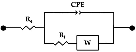
Figure 8.
Randles EEC modified with a CPE to simulate the behavior of the steel embedded in concrete (concrete-steel interface). Where: Re—ohmic resistance of the concrete; CPE—constant phase element that replaces the double layer capacitance at the steel rebar surface; and the corresponding charge transfer resistance—Rt; W—Warburg impedance [161,165,211].
This EEC can be used to determine quantitative aspects of the electrochemical behavior of the steel-concrete interface and therefore provide information on the corrosion state of the steel embedded in the concrete (e.g., whether the steel is passive or active) [212]. EIS has been also used to characterize the electrochemical behavior of stainless steels, when exposed to simulated concrete pore solution [161,209].
3.1.4. Galvanic Current
The study of corrosion of concrete contaminated with chlorides has led to the development of an embedded sensor based on the measurement of galvanic current (igal) in macrocells [67]. This type of sensor is based on concrete with construction steels and nobler metals, which are usually stainless steel. The igal generated when depassivation of steel reinforcement occurs, due to contamination of the concrete with aggressive agents, is measured. The construction steel sections act as anodes and the stainless steel sections act as a cathode. As the penetration of aggressive agents in the concrete progresses, the corrosion of the first anode begins to generate a igal. By simultaneously monitoring successive sections of construction steel embedded at different depths, it is possible to detect the moment at which the depassivation of steel reinforcement occurs for each depth. Figure 9 shows a schematic representation of a sensor composed by several rebars (construction steel) embedded in concrete at different depths (anodes) and a stainless steel rod that will act as cathode.
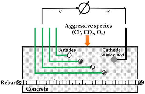
Figure 9.
Schematic representation of a sensor based on the measurement of igal in macrocells (reproduced and adapted from [220]).
This system shows if the reinforcement will corrode and when corrosion will start. Therefore, corrosion protection measures can be planned and carried out before the spalls and cracks are visible. Nevertheless, this corrosion monitoring system does not allow determination of the absolute chloride contents. It only determines the depth of the critical chloride content. This is an advantage as the interpretation of absolute chloride contents is quite challenging. The critical chloride content for reinforcement corrosion depends on concrete composition [19,20,21,213,214,215], rebar surface finishing [12,25,216,217], environmental conditions [20,218,219], and others [11,15,23,213,214,215].
According to Raupach [221], the influence of temperature in igal in macrocells might be quantified as:
where: I is the current intensity at temperature T (in A); I0 is the current at temperature T0 (in A); T and T0 are absolute temperatures (in K); a is a constant (in K) and depends on the degree of saturation of concrete.
In 2009, Figueira et al. [82,182] reported a study on the development of igal sensors (Figure 10) in saturated Ca(OH)2 aqueous solutions. Several conditions simulating the most important parameters that can affect the corrosion of concrete in RCS were studied, such as carbonation, ingress of chloride ions and O2. In all cases, the influence of time and temperature (25 to 55 °C) were considered.
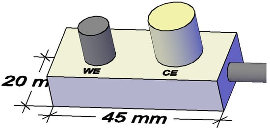
Figure 10.
Schematic representation of the igal sensor (WE—working electrode and CE—counter electrode). Reprinted with permission from Sensors MDPI [82].
Figure 11 shows the igal values of the steel-working electrode vs. immersion time under the different experimental conditions studied. The results showed that for the steel in the passive state no variation of igal was found (Figure 11a). As the pH was lowered (from 12.5 (Figure 11a) to 9.5 (Figure 11b–d), the process was influenced by the temperature. Higher igal values were obtained for higher temperature values either in the presence of Cl− or the absence of O2 (Figure 11b–d). Figure 11 also shows that due to the formation of oxides on the working electrode surface, a decrease of igal with time was recorded (Figure 11c,d). A relationship between the galvanic currents and the corrosion rates of reinforcing steel, under a great variety of controlled laboratorial conditions, was also established. The authors have shown that icorr ≈ 10 9/2 igal 6/5 [82,182].
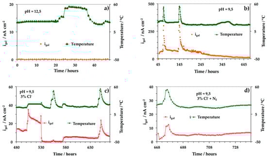
Figure 11.
igal values of the steel working electrode vs. immersion time under the following experimental conditions: (a) saturated Ca(OH)2 solution, pH 12.5; (b) saturated Ca(OH)2 + CO2, pH 9.5; (c) saturated Ca(OH)2 + CO2 + 3% Cl−; (d) saturated Ca(OH)2 + CO2 + 3% Cl− + N2 (O2 depletion). For each condition, temperatures of 25, 35 and 55 °C have been set and the corresponding measurements have been performed [182].
3.2. Limitations of Electrochemical Sensors for Corrosion Monitoring of RCS
Several corrosion-monitoring sensors have been proposed for corrosion monitoring of RCS. The published papers show that when the electrochemical techniques are correctly employed, they provide fast, quantitative, and reliable information. However, most of sensors introduced so far have some limitations and constraints to reach the reliable status to monitor and assess corrosion reinforcement continuously, accurately and for long time periods. The main constraints are linked to the durability, sensitivity to electromagnetic interference and stability of the sensors over time. Each electrochemical technique has advantages and limitations. To obtain accurate and reliable information about the corrosion reinforcement over time of a particular RCS, the combination of different techniques is an essential condition. For instance, OCP measurements are found to be linked with several practical limitations such as establishing connection with reinforcement, particularly in structures with a large concrete cover. As mentioned previously, OCP measurements can only provide information of the area likely to be corroded and no assessment of the corrosion rate; e.g., OCP values are only indicative of the probability of corrosion activity of reinforcement. Furthermore, OCP measurements cannot provide reliable results with epoxy-coated reinforcement or with coated concrete surfaces and are highly influenced by moist or wetting condition of concrete and by the composition of the concrete. The analysis criteria should be carefully performed since may change for different aggressive environments [222].
Recently, Pereira et al. [223] studied corrosion induced by chlorides, and the Rp values obtained by different methods such as potentiodynamic, potentiostatic, galvanostatic polarization, and EIS. The authors concluded that all the methods lead to the same values for Rp. Furthermore, the authors proved that detailed information of the steel/concrete system was given by the EIS method. However, some limitations exist. EIS is a time consuming method when applied in a large range of frequencies. The interpretation of results is challenging and needs suitable EECs that are dependent on the steel surface condition. Moreover, in EIS the measured steel surface area is not easily quantifiable. For galvanostatic method the authors concluded that previous knowledge of the current density to be applied was necessary and in the case of steel in a passive state, higher polarization could destroy the sensor [223]. Concerning the potentiodynamic and the potentiostatic methods, the authors reported that the second was more advantageous since it was a faster method and the ohmic drop for the correction of the measured Rp value was easily obtained [223]. One of the limitations of the galvanostatic method is that the response to the pulse needs to be stabilized to provide a reliable value for Vmax. The main constraints are linked to the time necessary to achieve an equilibrium value for Vmax which, if not achieved, may lead to deviations from the expected behavior and therefore mistakes in the assessment of the system-related parameters (Rp and Cdl), which may turn into over- or underestimation of the corrosion rate.
3.3. Future and Research Challenges of Sensors for Corrosion Monitoring of RCS
The development of monitoring systems for new and existing RCS allows a rational approach to the assessment of repair options and schedule of inspection and maintenance programs. In the last few decades, different types of electrochemical and optical systems for corrosion monitoring have been developed. The high interest in optical sensors has led to the publication of several review articles in recent years [61,224,225,226,227,228,229]. Fiber-optical sensors (FOS) are small, lightweight, robust, corrosion resistant, immune to electro-magnetic interference, highly sensitive and can be tuned to detect different signals. They are suitable for use in severe environments such as RCS. They allow a continuous and permanent observation of the corrosion conditions of RCS and can be used as early warning systems in critical situations. The massive development of electronics, will undoubtedly, lead to the development of powerful and low-cost data acquisition systems, data transfer, storage and assessment [96].
The development of integrated monitoring systems (optical and electrochemical systems) for new and existing RCS is an area that has expanded in the last few years. Several sensors based on electrical and optical fiber technology [49,224,225,230] have been reported and have demonstrated that they can monitor several physical and chemical properties of concrete directly related to RCS durability. Each system shows advantages and disadvantages. Therefore, the combination of both methods will ensure a proper maintenance strategy with decreased repair and rehabilitation costs of new and existing RCS.
Effective systems to monitor the durability of RCS require sensors that can be embedded in the concrete. Desirable properties are (i) robustness; (ii) good design and location (cover zone of concrete), (iii) high reproducibility and sensitivity; (iv) low cost, (v) environmentally friendly and (vi) easy to store data. Currently, most research focuses on the development of advanced sensing technology, and sensor and durability monitoring. Numerous smart sensors, such as FOS [231,232,233,234], cement-based strain sensors [235,236] and nanomaterial-based sensors [237] have been implemented in several structures. Multifunctional sensors have also been developed such as investigation of the pH, moisture or relative humidity, chloride ion concentration and the corrosion rate of the steel rebar [238,239]. However, most of them show poor and inconsistent responses [240,241], drifting of the signal due to dye leaching [238], reduced lifetime [241,242] or unsuitability to operate at a pH > 12 [224,241,242]. Additionally, embedding several conducting wires for corrosion monitoring of RCS is very laborious and expensive, therefore, in the future it should be minimized or avoided.
Cutting-edge nanotechnology/microelectromechanical systems (MEMS) represent another innovative solution for monitoring RCS. In 2008, Norris et al. explored, for the first time, the feasibility of using MEMS devices as embedded sensors to monitor concrete temperature and internal humidity [108]. MEMS devices are manufactured using identical materials and processes as microelectronic devices such as memory chips and microprocessors. These methods allow the obtaining of small and low-cost devices that can be distributed, in number (from hundreds to millions) throughout a RCS. The common manufacturing process also allows the integration of mechanical actuators with electronics for control, processing and communication. MEMS technology has the potential to measure the properties of interest directly ensuring a good coverage of a structure. The MEMS size and encapsulated nature avoids damage while wireless technologies make them easy to interrogate. MEMS-based systems have integrated technologies that allow structural health monitoring and condition assessment of RCS [108,243].
4. Conclusions
The actual state of the art in the field of electrochemical sensors based on non-destructive methods for corrosion monitoring of RCS was reviewed. The most common causes of reinforcement corrosion are Cl− and carbonation by atmospheric CO2. The corrosion monitoring of RCS can be performed using different sensors and methods and is a crucial part of planned maintenance and life prediction. The data obtained from corrosion monitoring provides quantitative information about the corrosion development of RCS exposed to aggressive environments. It can also be used to assess the effectiveness of repair and rehabilitation interventions by assessing the behavior of repairing systems such as coatings or corrosion inhibitors and to determine the future repair cycle.
The use of a corrosion monitoring system is particularly economic in locations with difficult access, such as at the tidal zones of bridges and pier shafts. Furthermore, the success of a corrosion monitoring system relies on the fact that it must be considered as part of effective maintenance management for a RCS. A corrosion monitoring system cannot be the only measure for maintenance, but as an integrated measure of the whole maintenance program for a RCS.
The studies revealed that the number of engineers and scientists, with proper education and experience in the field of corrosion of RCS, has grown considerably in the last two decades.
Furthermore, over the past few years, the corrosion monitoring systems for new and existing RCS have achieved a high level of development. Improvements have been more evident in the development of durable, low-cost embeddable sensors and microprocessor control and communications. Furthermore, the studies published indicate that the measurements of corrosion potential or concrete resistivity are very useful techniques to characterize the corrosion state of a RCS. However, the corrosion process can only be quantified by icorr measurements. The studies generally allow a conclusion that the RCSs exposed to aggressive environments have a considerable icorr variation. Therefore, it is necessary, in the short term, to establish a methodology in order to define, with a high accuracy level, representative values of icorr in certain environments.
Conflicts of Interest
The author declares no conflict of interest.
References
- Ahmad, S. Reinforcement corrosion in concrete structures, its monitoring and service life prediction––A review. Cem. Concr. Compos. 2003, 25, 459–471. [Google Scholar] [CrossRef]
- Böhni, H. Corrosion in Reinforced Concrete Structures; Elsevier: Amsterdam, The Netherlands, 2005; ISBN 978-1-84569-043-4. [Google Scholar]
- Andrade, C. 14—Future trends in research on reinforcement corrosion A2—Poursaee, Amir. In Corrosion of Steel in Concrete Structures; Woodhead Publishing: Oxford, UK, 2016; pp. 269–288. ISBN 978-1-78242-381-2. [Google Scholar]
- Liberati, E.A.P.; Nogueira, C.G.; Leonel, E.D.; Chateauneuf, A. Chapter 5—Failure analysis of reinforced concrete structures subjected to chloride penetration and reinforcements corrosion A2—Makhlouf, Abdel Salam Hamdy. In Handbook of Materials Failure Analysis with Case Studies from the Chemicals, Concrete and Power Industries; Aliofkhazraei, M., Ed.; Butterworth-Heinemann: Oxford, UK, 2016; pp. 93–121. ISBN 978-0-08-100116-5. [Google Scholar]
- Bertolini, L.; Elsener, B.; Pedeferri, P.; Redaelli, E.; Polder, R.B. Corrosion of Steel in Concrete: Prevention, Diagnosis, Repair, 2nd ed.; John Wiley & Sons, Inc.: Hoboken, NJ, USA, 2013. [Google Scholar]
- Dhawan, S.; Bhalla, S.; Bhattacharjee, B. Reinforcement Corrosion in Concrete Structures and Service Life Predictions—A Review. In Proceedings of the 9th International Symposium on Advanced Science and Technology in Experimental Mechanics, New Delhi, India, 1–6 November 2014. [Google Scholar]
- Bertolini, L. Steel corrosion and service life of reinforced concrete structures. Struct. Infrastruct. Eng. 2008, 4, 123–137. [Google Scholar] [CrossRef]
- Parrott, L.J. A Review of Carbonation in Reinforced Concrete; Cement and Concrete Association: Camberley, UK, 1987; ISBN 978-0-7210-1365-7. [Google Scholar]
- Richardson, M.G. Fundamentals of Durable Reinforced Concrete; CRC Press: Boca Raton, FL, USA, 2003; ISBN 978-0-203-22319-2. [Google Scholar]
- Geng, J.; Easterbrook, D.; Liu, Q.-F.; Li, L.-Y. Effect of carbonation on release of bound chlorides in chloride-contaminated concrete. Mag. Concr. Res. 2015, 68, 353–363. [Google Scholar] [CrossRef]
- Hussain, S.E.; Al-Musallam, A.; Al-Gahtani, A.S. Factors affecting threshold chloride for reinforcement corrosion in concrete. Cem. Concr. Res. 1995, 25, 1543–1555. [Google Scholar] [CrossRef]
- Mammoliti, L.T.; Brown, L.C.; Hansson, C.M.; Hope, B.B. The influence of surface finish of reinforcing steel and pH of the test solution on the chloride threshold concentration for corrosion initiation in synthetic pore solutions. Cem. Concr. Res. 1996, 26, 545–550. [Google Scholar] [CrossRef]
- Alonso, C.; Andrade, C.; Castellote, M.; Castro, P. Chloride threshold values to depassivate reinforcing bars embedded in a standardized OPC mortar. Cem. Concr. Res. 2000, 30, 1047–1055. [Google Scholar] [CrossRef]
- Li, L.; Sagüés, A.A. Chloride Corrosion Threshold of Reinforcing Steel in Alkaline Solutions—Open-Circuit Immersion Tests. Corrosion 2001, 57, 19–28. [Google Scholar] [CrossRef]
- Alonso, C.; Castellote, M.; Andrade, C. Chloride threshold dependence of pitting potential of reinforcements. Electrochim. Acta 2002, 47, 3469–3481. [Google Scholar] [CrossRef]
- Li, L.; Sagüés, A.A. Chloride Corrosion Threshold of Reinforcing Steel in Alkaline Solutions—Cyclic Polarization Behavior. Corrosion 2002, 58, 305–316. [Google Scholar] [CrossRef]
- Izquierdo, D.; Alonso, C.; Andrade, C.; Castellote, M. Potentiostatic determination of chloride threshold values for rebar depassivation: Experimental and statistical study. Electrochim. Acta 2004, 49, 2731–2739. [Google Scholar] [CrossRef]
- Trejo, D.; Monteiro, P.J. Corrosion performance of conventional (ASTM A615) and low-alloy (ASTM A706) reinforcing bars embedded in concrete and exposed to chloride environments. Cem. Concr. Res. 2005, 35, 562–571. [Google Scholar] [CrossRef]
- Manera, M.; Vennesland, Ø.; Bertolini, L. Chloride threshold for rebar corrosion in concrete with addition of silica fume. Corros. Sci. 2008, 50, 554–560. [Google Scholar] [CrossRef]
- Cheewaket, T.; Jaturapitakkul, C.; Chalee, W. Initial corrosion presented by chloride threshold penetration of concrete up to 10 year-results under marine site. Constr. Build. Mater. 2012, 37, 693–698. [Google Scholar] [CrossRef]
- Xu, J.; Jiang, L.; Wang, W.; Jiang, Y. Influence of CaCl2 and NaCl from different sources on chloride threshold value for the corrosion of steel reinforcement in concrete. Constr. Build. Mater. 2011, 25, 663–669. [Google Scholar] [CrossRef]
- Silva, N. Chloride Induced Corrosion of Reinforcement Steel in Concrete: Threshold Values and Ion Distributions at the Concrete-Steel Interface; Doktorsavhandlingar vid Chalmers Tekniska Högskola; Chalmers University of Technology: Göteborg, Sweden, 2013; ISBN 978-91-7385-808-3. [Google Scholar]
- Jiang, L.; Liu, H.; Wang, Y.; Zhang, Y.; Song, Z.; Xu, J.; Jin, M.; Jiang, P.; Xu, Y.; Gao, H. Influence of flexural fatigue on chloride threshold value for the corrosion of steels in Ca(OH)2 solutions. Mater. Chem. Phys. 2015, 164, 23–28. [Google Scholar] [CrossRef]
- Liu, R.; Jiang, L.; Huang, G.; Zhu, Y.; Liu, X.; Chu, H.; Xiong, C. The effect of carbonate and sulfate ions on chloride threshold level of reinforcement corrosion in mortar with/without fly ash. Constr. Build. Mater. 2016, 113, 90–95. [Google Scholar] [CrossRef]
- Figueira, R.B.; Sadovski, A.; Melo, A.P.; Pereira, E.V. Chloride threshold value to initiate reinforcement corrosion in simulated concrete pore solutions: The influence of surface finishing and pH. Constr. Build. Mater. 2017, 141, 183–200. [Google Scholar] [CrossRef]
- Bastidas-Arteaga, E.; Chateauneuf, A.; Sánchez-Silva, M.; Bressolette, P.; Schoefs, F. A comprehensive probabilistic model of chloride ingress in unsaturated concrete. Eng. Struct. 2011, 33, 720–730. [Google Scholar] [CrossRef]
- Duprat, F.; Vu, N.T. A probabilistic threshold for the onset of carbonation-induced corrosion. Eur. J. Environ. Civ. Eng. 2013, 17, 478–495. [Google Scholar] [CrossRef]
- Kong, J.S.; Ababneh, A.N.; Frangopol, D.M.; Xi, Y. Reliability analysis of chloride penetration in saturated concrete. Probabilistic Eng. Mech. 2002, 17, 305–315. [Google Scholar] [CrossRef]
- Duprat, F.; Vu, N.T.; Sellier, A. Accelerated carbonation tests for the probabilistic prediction of the durability of concrete structures. Constr. Build. Mater. 2014, 66, 597–605. [Google Scholar] [CrossRef]
- Lu, C.; Yuan, S.; Liu, R. Experimental and probabilistic analysis of time to corrosion-induced cover cracking for marine reinforced concrete structures. Corros. Eng. Sci. Technol. 2017, 52, 124–133. [Google Scholar] [CrossRef]
- Nogueira, C.G.; Leonel, E.D. Probabilistic models applied to safety assessment of reinforced concrete structures subjected to chloride ingress. Eng. Fail. Anal. 2013, 31, 76–89. [Google Scholar] [CrossRef]
- Ryan, P.C.; O’Connor, A.J. Probabilistic analysis of the time to chloride induced corrosion for different Self-Compacting Concretes. Constr. Build. Mater. 2013, 47, 1106–1116. [Google Scholar] [CrossRef]
- Saassouh, B.; Lounis, Z. Probabilistic modeling of chloride-induced corrosion in concrete structures using first- and second-order reliability methods. Cem. Concr. Compos. 2012, 34, 1082–1093. [Google Scholar] [CrossRef]
- Val, D.V.; Trapper, P.A. Probabilistic evaluation of initiation time of chloride-induced corrosion. Reliab. Eng. Syst. Saf. 2008, 93, 364–372. [Google Scholar] [CrossRef]
- Wu, L.; Kou, X.; Jiang, M. Probabilistic Corrosion Initiation Time Assessment of Existing Concrete Structures Under Marine Environment. Arab. J. Sci. Eng. 2015, 40, 3099–3105. [Google Scholar] [CrossRef]
- Yu, B.; Ning, C.; Li, B. Probabilistic durability assessment of concrete structures in marine environments: Reliability and sensitivity analysis. China Ocean Eng. 2017, 31, 63–73. [Google Scholar] [CrossRef]
- Zhu, X.; Zi, G.; Lee, W.; Kim, S.; Kong, J. Probabilistic analysis of reinforcement corrosion due to the combined action of carbonation and chloride ingress in concrete. Constr. Build. Mater. 2016, 124, 667–680. [Google Scholar] [CrossRef]
- Faustino, P.; Chastre, C.; Nunes, Â.; Brás, A. Lifetime modeling of chloride-induced corrosion in concrete structures with Portland and blended cements. Struct. Infrastruct. Eng. 2016, 12, 1013–1023. [Google Scholar] [CrossRef]
- Suo, Q.; Stewart, M.G. Corrosion cracking prediction updating of deteriorating RC structures using inspection information. Reliab. Eng. Syst. Saf. 2009, 94, 1340–1348. [Google Scholar] [CrossRef]
- Stewart, M.G.; Mullard, J.A. Spatial time-dependent reliability analysis of corrosion damage and the timing of first repair for RC structures. Eng. Struct. 2007, 29, 1457–1464. [Google Scholar] [CrossRef]
- Feliu, S. Modelling of the steel—Concrete interface to obtain information on reinforcement bar corrosion. J. Appl. Electrochem. 2005, 1, 429–436. [Google Scholar] [CrossRef]
- Cao, C.; Cheung, M.M.S.; Chan, B.Y.B. Modelling of interaction between corrosion-induced concrete cover crack and steel corrosion rate. Corros. Sci. 2013, 69, 97–109. [Google Scholar] [CrossRef]
- Gulikers, J. Theoretical considerations on the supposed linear relationship between concrete resistivity and corrosion rate of steel reinforcement. Mater. Corros. 2005, 56, 393–403. [Google Scholar] [CrossRef]
- Isgor, O.B.; Razaqpur, A.G. Modelling steel corrosion in concrete structures. Mater. Struct. 2006, 39, 291–302. [Google Scholar] [CrossRef]
- Amin, M.A.; Abd El Rehim, S.S.; Abdel-Fatah, H.T.M. Electrochemical frequency modulation and inductively coupled plasma atomic emission spectroscopy methods for monitoring corrosion rates and inhibition of low alloy steel corrosion in HCl solutions and a test for validity of the Tafel extrapolation method. Corros. Sci. 2009, 51, 882–894. [Google Scholar] [CrossRef]
- Andrade, C.; Alonso, C. Corrosion rate monitoring in the laboratory and on-site. Constr. Build. Mater. 1996, 10, 315–328. [Google Scholar] [CrossRef]
- Angst, U.M.; Elsener, B.; Larsen, C.K.; Vennesland, Ø. Chloride induced reinforcement corrosion: Electrochemical monitoring of initiation stage and chloride threshold values. Corros. Sci. 2011, 53, 1451–1464. [Google Scholar] [CrossRef]
- Ervin, B.L. Monitoring Corrosion of Rebar Embedded in Mortar Using Guided Ultrasonic Waves; ProQuest: Ann Arbor, MI, USA, 2007; ISBN 978-0-549-33994-6. [Google Scholar]
- Gao, J.; Wu, J.; Li, J.; Zhao, X. Monitoring of corrosion in reinforced concrete structure using Bragg grating sensing. NDT E Int. 2011, 44, 202–205. [Google Scholar] [CrossRef]
- Song, H.-W.; Saraswathy, V. Corrosion Monitoring of Reinforced Concrete Structures—A Review. Int. J. Electrochem. Sci. 2007, 2, 1–28. [Google Scholar]
- Qiao, G.; Sun, G.; Hong, Y.; Liu, T.; Guan, X. Corrosion in Reinforced Concrete Panels: Wireless Monitoring and Wavelet-Based Analysis. Sensors 2014, 14, 3395–3407. [Google Scholar] [CrossRef] [PubMed]
- Rahman, S.A.; Ismail, M.; Noor, N.M.; Bakhtiar, H. Embedded capacitor sensor for monitoring corrosion of reinforcement in concrete. J. Eng. Sci. Technol. 2012, 7, 209–218. [Google Scholar]
- Legat, A. Monitoring of steel corrosion in concrete by electrode arrays and electrical resistance probes. Electrochim. Acta 2007, 52, 7590–7598. [Google Scholar] [CrossRef]
- Yang, L.; Yang, T.T.; Zhou, Y.C.; Wei, Y.G.; Wu, R.T.; Wang, N.G. Acoustic emission monitoring and damage mode discrimination of APS thermal barrier coatings under high temperature CMAS corrosion. Surf. Coat. Technol. 2016, 304, 272–282. [Google Scholar] [CrossRef]
- Helal, J.; Sofi, M.; Mendis, P. Non-destructive testing of concrete: A review of methods. Electron. J. Struct. Eng. 2015, 14, 97–105. [Google Scholar]
- British Standards Institution. Non-Destructive Testing: Visual Testing: General Principles; British Standards Institution: London, UK, 2001; ISBN 978-0-580-37215-5. [Google Scholar]
- Maierhofer, C.; Reinhardt, H.-W.; Dobmann, G. Non-Destructive Evaluation of Reinforced Concrete Structures: Non-Destructive Testing Methods; Elsevier: Amsterdam, The Netherlands, 2010; ISBN 978-1-84569-960-4. [Google Scholar]
- Malek, J.; Kaouther, M. Destructive and Non-destructive Testing of Concrete Structures. Jordan J. Civ. Eng. 2014, 8, 432–441. [Google Scholar]
- Pucinotti, R. Reinforced concrete structure: Non destructive in situ strength assessment of concrete. Constr. Build. Mater. 2015, 75, 331–341. [Google Scholar] [CrossRef]
- García-Martín, J.; Gómez-Gil, J.; Vázquez-Sánchez, E. Non-Destructive Techniques Based on Eddy Current Testing. Sensors 2011, 11, 2525–2565. [Google Scholar] [CrossRef] [PubMed]
- Zaki, A.; Chai, H.K.; Aggelis, D.G.; Alver, N. Non-Destructive Evaluation for Corrosion Monitoring in Concrete: A Review and Capability of Acoustic Emission Technique. Sensors 2015, 15, 19069–19101. [Google Scholar] [CrossRef] [PubMed]
- 17/30351884 DC—BS EN 12390-10. Testing Hardened Concrete. Part 10. Determination of the Carbonation Resistance of Concrete at Atmospheric Levels of Carbon 17/30351884 DC—BS EN 12390-10. Testing Hardened Concrete. Part 10. Determination of the Carbonation Resistance of Concrete at Atmospheric Levels of Carbon Dioxide. Available online: https://shop.bsigroup.com/ProductDetail?pid=000000000030351884 (accessed on 22 August 2017).
- BS EN 14630:2006—Products and Systems for the Protection and Repair of Concrete Structures. Test Methods. Determination of Carbonation Depth in Hardened Concrete by the Phenolphthalein Method. Available online: https://shop.bsigroup.com/ProductDetail?pid=000000000030091526 (accessed on 22 August 2017).
- BS EN 12390-11:2015—Testing Hardened Concrete. Determination of the Chloride Resistance of Concrete, Unidirectional Diffusion. Available online: https://shop.bsigroup.com/ProductDetail/?pid=000000000030314030 (accessed on 22 August 2017).
- Raupach, M.; Elsener, B.; Polder, R.; Mietz, J. Corrosion of Reinforcement in Concrete: Mechanisms, Monitoring, Inhibitors and Rehabilitation Techniques; Woodhead Publishing: Cambridge, UK; CRC Press: Boca Raton, FL, USA, 2007; ISBN 1-84569-210-1. [Google Scholar]
- Schuten, G.; Leggedoor, J.; Polder, R.B.; Peelen, W.H.A. 24—Renovation of the cathodic protection system of a concrete bridge after 12 years of operation. In Corrosion of Reinforcement in Concrete; Raupach, M., Ed.; European Federation of Corrosion (EFC) Series; Woodhead Publishing: Cambridge, UK, 2007; pp. 300–306. ISBN 978-1-84569-210-0. [Google Scholar]
- Schiessl, P.; Raupach, M. Monitoring System for the Corrosion Risk of Steel in Concrete Structures. Concr. Int. 1992, 14, 52–55. [Google Scholar]
- Nili, M.; Razmara, M.; Nili, M.; Razmara, P. Proposing new methods to appraise segregation resistance of self-consolidating concrete based on electrical resistivity. Constr. Build. Mater. 2017, 146, 192–198. [Google Scholar] [CrossRef]
- Morris, W.; Vico, A.; Vazquez, M.; de Sanchez, S.R. Corrosion of reinforcing steel evaluated by means of concrete resistivity measurements. Corros. Sci. 2002, 44, 81–99. [Google Scholar] [CrossRef]
- Elsener, B. Corrosion rate of steel in concrete—Measurements beyond the Tafel law. Corros. Sci. 2005, 47, 3019–3033. [Google Scholar] [CrossRef]
- Myrdal, R. The Electrochemistry and Characteristics of Embeddable Reference Electrodes for Concrete; Woodhead Publishing: Cambridge, UK, 2014; ISBN 978-1-84569-255-1. [Google Scholar]
- Correia, M.J.; Pereira, E.V.; Salta, M.M.; Fonseca, I.T.E. Sensor for oxygen evaluation in concrete. Cem. Concr. Compos. 2006, 28, 226–232. [Google Scholar] [CrossRef]
- McCarter, W.J.; Vennesland, Ø. Sensor systems for use in reinforced concrete structures. Constr. Build. Mater. 2004, 18, 351–358. [Google Scholar] [CrossRef]
- Page, C.L.; Treadaway, K.W.J. Aspects of the electrochemistry of steel in concrete. Nature 1982, 297, 109–115. [Google Scholar] [CrossRef]
- Romano, P.; Brito, P.S.D.; Rodrigues, L. Monitoring of the degradation of concrete structures in environments containing chloride ions. Constr. Build. Mater. 2013, 47, 827–832. [Google Scholar] [CrossRef]
- Bergmeister, K.; Santa, U. Structural Health Monitoring of Concrete Bridges. In Interferometry in Speckle Light; Springer: Berlin/Heidelberg, Germany, 2000; pp. 633–640. ISBN 978-3-642-63230-3. [Google Scholar]
- Gro Markeset, V.O. Critical Chloride Content in Reinforced Concrete COIN Workshop, 5–6 June 2008, Trondheim, Norway; Institute of Materials: London, UK, 2008. [Google Scholar]
- Duffó, G.S.; Farina, S.B. Development of an embeddable sensor to monitor the corrosion process of new and existing reinforced concrete structures. Constr. Build. Mater. 2009, 23, 2746–2751. [Google Scholar] [CrossRef]
- Karthick, S.P.; Muralidharan, S.; Saraswathy, V.; Thangavel, K. Long-term relative performance of embedded sensor and surface mounted electrode for corrosion monitoring of steel in concrete structures. Sens. Actuators B Chem. 2014, 192, 303–309. [Google Scholar] [CrossRef]
- Pereira, E.V.; Figueira, R.B.; Salta, M.M.; Fonseca, I.T.E. Embedded Sensors for Corrosion Monitoring of Existing Reinforced Concrete Structures. Mater. Sci. Forum 2008, 587–588, 677–681. [Google Scholar] [CrossRef]
- Andrade, C.; Castelo, V.; Alonso, C.; González, J. The Determination of the Corrosion Rate of Steel Embedded in Concrete by the Polarization Resistance and AC Impedance Methods. In Corrosion Effect of Stary Currents and the Techniques for Evaluating Corrosion of Rebars in Concrete; Chaker, V., Ed.; ASTM International: West Conshohocken, PA, USA, 1986; ISBN 978-0-8031-0468-6. [Google Scholar]
- Pereira, E.V.; Figueira, R.B.; Salta, M.M.L.; da Fonseca, I.T.E. A Galvanic Sensor for Monitoring the Corrosion Condition of the Concrete Reinforcing Steel: Relationship between the Galvanic and the Corrosion Currents. Sensors 2009, 9, 8391–8398. [Google Scholar] [CrossRef] [PubMed]
- Allahar, K.; Su, Q.; Bierwagen, G. Non-substrate EIS monitoring of organic coatings with embedded electrodes. Prog. Org. Coat. 2010, 67, 180–187. [Google Scholar] [CrossRef]
- Andrade, C.; Alonso, C. Test methods for on-site corrosion rate measurement of steel reinforcement in concrete by means of the polarization resistance method. Mater. Struct. 2004, 37, 623–643. [Google Scholar] [CrossRef]
- Qiao, G.; Liu, T. Characterization of the reinforcing steel corrosion by potentialdynamic scan approach. J. Wuhan Univ. Technol.-Mater. Sci. Ed. 2012, 27, 418–421. [Google Scholar] [CrossRef]
- Gandía-Romero, J.M.; Bataller, R.; Monzón, P.; Campos, I.; García-Breijo, E.; Valcuende, M.; Soto, J. Characterization of embeddable potentiometric thick-film sensors for monitoring chloride penetration in concrete. Sens. Actuators B Chem. 2016, 222, 407–418. [Google Scholar] [CrossRef]
- Jin, M.; Jiang, L.; Zhu, Q. Monitoring chloride ion penetration in concrete with different mineral admixtures based on embedded chloride ion selective electrodes. Constr. Build. Mater. 2017, 143, 1–15. [Google Scholar] [CrossRef]
- Martínez, I.; Andrade, C. Examples of reinforcement corrosion monitoring by embedded sensors in concrete structures. Cem. Concr. Compos. 2009, 31, 545–554. [Google Scholar] [CrossRef]
- Muralidharan, S.; Ha, T.H.; Bae, J.H.; Ha, Y.C.; Lee, H.G.; Kim, D.K. A promising potential embeddable sensor for corrosion monitoring application in concrete structures. Measurement 2007, 40, 600–606. [Google Scholar] [CrossRef]
- Park, Z.-T.; Choi, Y.-S.; Kim, J.-G.; Chung, L. Development of a galvanic sensor system for detecting the corrosion damage of the steel embedded in concrete structure. Cem. Concr. Res. 2005, 35, 1814–1819. [Google Scholar] [CrossRef]
- Bhadra, S.; Thomson, D.J.; Bridges, G.E. A wireless embedded passive sensor for monitoring the corrosion potential of reinforcing steel. Smart Mater. Struct. 2013, 22, 75019. [Google Scholar] [CrossRef]
- Qiao, G.; Sun, G.; Hong, Y.; Qiu, Y.; Ou, J. Remote corrosion monitoring of the RC structures using the electrochemical wireless energy-harvesting sensors and networks. NDT E Int. 2011, 44, 583–588. [Google Scholar] [CrossRef]
- Barroca, N.; Borges, L.M.; Velez, F.J.; Monteiro, F.; Górski, M.; Castro-Gomes, J. Wireless sensor networks for temperature and humidity monitoring within concrete structures. Constr. Build. Mater. 2013, 40, 1156–1166. [Google Scholar] [CrossRef]
- Chalioris, C.E.; Karayannis, C.G.; Angeli, G.M.; Papadopoulos, N.A.; Favvata, M.J.; Providakis, C.P. Applications of smart piezoelectric materials in a wireless admittance monitoring system (WiAMS) to Structures—Tests in RC elements. Case Stud. Constr. Mater. 2016, 5, 1–18. [Google Scholar] [CrossRef]
- Abbas, Y.; ten Have, B.; Hoekstra, G.I.; Douma, A.; de Bruijn, D.; Olthuis, W.; van den Berg, A. Connecting to Concrete: Wireless Monitoring of Chloride ions in Concrete structures. Procedia Eng. 2015, 120, 965–968. [Google Scholar] [CrossRef]
- Raupach, M.; Gulikers, J.; Reichling, K. Condition survey with embedded sensors regarding reinforcement corrosion. Mater. Corros. 2013, 64, 141–146. [Google Scholar] [CrossRef]
- Xu, C.; Li, Z.; Jin, W. A New Corrosion Sensor to Determine the Start and Development of Embedded Rebar Corrosion Process at Coastal Concrete. Sensors 2013, 13, 13258–13275. [Google Scholar] [CrossRef] [PubMed]
- Xu, D.; Banerjee, S.; Wang, Y.; Huang, S.; Cheng, X. Temperature and loading effects of embedded smart piezoelectric sensor for health monitoring of concrete structures. Constr. Build. Mater. 2015, 76, 187–193. [Google Scholar] [CrossRef]
- Jaśniok, T.; Jaśniok, M. Influence of Rapid Changes of Moisture Content in Concrete and Temperature on Corrosion Rate of Reinforcing Steel. Procedia Eng. 2015, 108, 316–323. [Google Scholar] [CrossRef]
- Jaśniok, M.; Jaśniok, T. Evaluation of Maximum and Minimum Corrosion Rate of Steel Rebars in Concrete Structures, Based on Laboratory Measurements on Drilled Cores. Procedia Eng. 2017, 193, 486–493. [Google Scholar] [CrossRef]
- Baccay, M.A.; Otsuki, N.; Nishida, T.; Maruyama, S. Influence of Cement Type and Temperature on the Rate of Corrosion of Steel in Concrete Exposed to Carbonation. Corrosion 2006, 62, 811–821. [Google Scholar] [CrossRef]
- Bouteiller, V.; Cherrier, J.-F.; L’Hostis, V.; Rebolledo, N.; Andrade, C.; Marie-Victoire, E. Influence of humidity and temperature on the corrosion of reinforced concrete prisms. Eur. J. Environ. Civ. Eng. 2012, 16, 471–480. [Google Scholar] [CrossRef]
- Otsuki, N.; Maruyama, S.; Nishida, T.; Alibuyog, B.M. Influence of Temperature on Corrosion Rate of Steel Bar in Carbonated Concrete Members. J. Soc. Mater. Sci. Jpn. 2004, 53, 108–113. [Google Scholar] [CrossRef][Green Version]
- Therefore, H.S.; Millard, S.G. On-site measurements on corrosion rate of steel in reinforced concrete. Mater. J. 2007, 104, 638–642. [Google Scholar]
- Yu, H.; Caseres, L. An embedded multi-parameter corrosion sensor for reinforced concrete structures. Mater. Corros. 2012, 63, 1011–1016. [Google Scholar] [CrossRef]
- Behnood, A.; Van Tittelboom, K.; De Belie, N. Methods for measuring pH in concrete: A review. Constr. Build. Mater. 2016, 105, 176–188. [Google Scholar] [CrossRef]
- Gandía-Romero, J.M.; Campos, I.; Valcuende, M.; García-Breijo, E.; Marcos, M.D.; Payá, J.; Soto, J. Potentiometric thick-film sensors for measuring the pH of concrete. Cem. Concr. Compos. 2016, 68, 66–76. [Google Scholar] [CrossRef]
- Norris, A.; Saafi, M.; Romine, P. Temperature and moisture monitoring in concrete structures using embedded nanotechnology/microelectromechanical systems (MEMS) sensors. Constr. Build. Mater. 2008, 22, 111–120. [Google Scholar] [CrossRef]
- Zhang, W.; Min, H.; Gu, X. Temperature response and moisture transport in damaged concrete under an atmospheric environment. Constr. Build. Mater. 2016, 123, 290–299. [Google Scholar] [CrossRef]
- Andringa, M.M.; Puryear, J.M.; Neikirk, D.P.; Wood, S.L. In situ measurement of conductivity and temperature during concrete curing using passive wireless sensors. Int. Soc. Opt. Photonics 2007, 6529, 65293M. [Google Scholar]
- Chu, H.; Chen, J. The experimental study on the correlation of resistivity and damage for conductive concrete. Cem. Concr. Compos. 2016, 67, 12–19. [Google Scholar] [CrossRef]
- Layssi, H.; Ghods, P.; Alizadeh, A.R.; Salehi, M. Electrical resistivity of concrete. Concr. Int. 2015, 37, 41–46. [Google Scholar]
- Sadowski, L. Methodology for Assessing the Probability of Corrosion in Concrete Structures on the Basis of Half-Cell Potential and Concrete Resistivity Measurements. Sci. World J. 2013, 2013, e714501. [Google Scholar] [CrossRef] [PubMed]
- Ohtsu, M.; Yamamoto, T. Compensation procedure for half-cell potential measurement. Constr. Build. Mater. 1997, 11, 395–402. [Google Scholar] [CrossRef]
- Assouli, B.; Ballivy, G.; Rivard, P. Influence of environmental parameters on application of standard ASTM C876-91: Half cell potential measurements. Corros. Eng. Sci. Technol. 2008, 43, 93–96. [Google Scholar] [CrossRef]
- Elsener, B.; Andrade, C.; Gulikers, J.; Polder, R.; Raupach, M. Hall-cell potential measurements—Potential mapping on reinforced concrete structures. Mater. Struct. 2003, 36, 461–471. [Google Scholar] [CrossRef]
- ASTM C876—15—Standard Test Method for Corrosion Potentials of Uncoated Reinforcing Steel in Concrete. Available online: https://shop.bsigroup.com/ProductDetail/?pid=000000000030342586 (accessed on 23 August 2017).
- Muralidharan, S.; Saraswathy, V.; Madhavamayandi, A.; Thangavel, K.; Palaniswamy, N. Evaluation of embeddable potential sensor for corrosion monitoring in concrete structures. Electrochim. Acta 2008, 53, 7248–7254. [Google Scholar] [CrossRef]
- Muralidharan, S.; Ha, T.-H.; Bae, J.-H.; Ha, Y.-C.; Lee, H.-G.; Park, K.-W.; Kim, D.-K. Electrochemical studies on the performance characteristics of solid metal–metal oxide reference sensor for concrete environments. Sens. Actuators B Chem. 2006, 113, 187–193. [Google Scholar] [CrossRef]
- Muralidharan, S.; Ha, T.-H.; Bae, J.-H.; Ha, Y.-C.; Lee, H.-G.; Park, K.-W.; Kim, D.-K. Electrochemical studies on the solid embeddable reference sensors for corrosion monitoring in concrete structure. Mater. Lett. 2006, 60, 651–655. [Google Scholar] [CrossRef]
- Muralidharan, S.; Saraswathy, V.; Thangavel, K.; Palaniswamy, N. Electrochemical studies on the performance characteristics of alkaline solid embeddable sensor for concrete environments. Sens. Actuators B Chem. 2008, 130, 864–870. [Google Scholar] [CrossRef]
- Duffó, G.S.; Farina, S.B.; Giordano, C.M. Characterization of solid embeddable reference electrodes for corrosion monitoring in reinforced concrete structures. Electrochim. Acta 2009, 54, 1010–1020. [Google Scholar] [CrossRef]
- Maruthapandian, V.; Saraswathy, V. Solid Nano Ferrite Embeddable Reference Electrode for Corrosion Monitoring in Reinforced Concrete Structures. Procedia Eng. 2014, 86, 623–630. [Google Scholar] [CrossRef]
- Maruthapandian, V.; Saraswathy, V.; Muralidharan, S. Development of solid state embeddable reference electrode for corrosioCORRn monitoring of steel in reinforced concrete structures. Cem. Concr. Compos. 2016, 74, 100–108. [Google Scholar] [CrossRef]
- Villela, T.; Souza, A.; Abdel-Rehim, H. Silver/Silver Chloride and Mercury/Mercurous Sulfate Standards Electrodes Confiability. Corrosion 2004, 60, 342–345. [Google Scholar] [CrossRef]
- Climent-Llorca, M.A.; Viqueira-Pérez, E.; López-Atalaya, M.M. Embeddable Ag/AgCl sensors for in situ monitoring chloride contents in concrete. Cem. Concr. Res. 1996, 26, 1157–1161. [Google Scholar] [CrossRef]
- Atkins, C.P.; Scantlebury, J.D.; Nedwell, P.J.; Blatch, S.P. Monitoring chloride concentrations in hardened cement pastes using ion selective electrodes. Cem. Concr. Res. 1996, 26, 319–324. [Google Scholar] [CrossRef]
- Montemor, M.F.; Alves, J.H.; Simões, A.M.; Fernandes, J.C.S.; Lourenço, Z.; Costa, A.J.S.; Appleton, A.J.; Ferreira, M.G.S. Multiprobe chloride sensor for in situ monitoring of reinforced concrete structures. Cem. Concr. Compos. 2006, 28, 233–236. [Google Scholar] [CrossRef]
- Feliu, S.; Andrade, C.; González, J.A.; Alonso, C. A new method forin situ measurement of electrical resistivity of reinforced concrete. Mater. Struct. 1996, 29, 362–365. [Google Scholar] [CrossRef]
- Polder, R.B. Test methods for on site measurement of resistivity of concrete—A RILEM TC-154 technical recommendation. Constr. Build. Mater. 2001, 15, 125–131. [Google Scholar] [CrossRef]
- Hornbostel, K.; Larsen, C.K.; Geiker, M.R. Relationship between concrete resistivity and corrosion rate—A literature review. Cem. Concr. Compos. 2013, 39, 60–72. [Google Scholar] [CrossRef]
- Yu, B.; Liu, J.; Chen, Z. Probabilistic evaluation method for corrosion risk of steel reinforcement based on concrete resistivity. Constr. Build. Mater. 2017, 138, 101–113. [Google Scholar] [CrossRef]
- Presuel-Moreno, F.; Wu, Y.-Y.; Liu, Y. Effect of curing regime on concrete resistivity and aging factor over time. Constr. Build. Mater. 2013, 48, 874–882. [Google Scholar] [CrossRef]
- Hornbostel, K.; Angst, U.M.; Elsener, B.; Larsen, C.K.; Geiker, M.R. Influence of mortar resistivity on the rate-limiting step of chloride-induced macro-cell corrosion of reinforcing steel. Corros. Sci. 2016, 110, 46–56. [Google Scholar] [CrossRef]
- Lim, Y.-C.; Noguchi, T.; Cho, C.-G. A quantitative analysis of the geometric effects of reinforcement in concrete resistivity measurement above reinforcement. Constr. Build. Mater. 2015, 83, 189–193. [Google Scholar] [CrossRef]
- Corrosion Rates of Steel in Concrete; Berke, N.S., Chaker, V., Whiting, D., Eds.; STP; ASTM: Philadelphia, PA, USA, 1990; ISBN 978-0-8031-1458-6. [Google Scholar]
- Feliu, S.; González, J.A.; Feliu, S.; Andrade, C. Relationship between conductivity of concrete and corrosion of reinforcing bars. Br. Corros. J. 1989, 24, 195–198. [Google Scholar] [CrossRef]
- Glass, G.K.; Page, C.L.; Short, N.R. Factors affecting the corrosion rate of steel in carbonated mortars. Corros. Sci. 1991, 32, 1283–1294. [Google Scholar] [CrossRef]
- Scott, A.; Alexander, M.G. The influence of binder type, cracking and cover on corrosion rates of steel in chloride-contaminated concrete. Mag. Concr. Res. 2007, 59, 495–505. [Google Scholar] [CrossRef]
- Yu, B.; Yang, L.; Wu, M.; Li, B. Practical model for predicting corrosion rate of steel reinforcement in concrete structures. Constr. Build. Mater. 2014, 54, 385–401. [Google Scholar] [CrossRef]
- NACE International; Grauer, R.; Moreland, P.J.; Pini, G. A Literature Review of Polarization Resistance Constant (B) Values for the Measurement of Corrosion Rate; National Assn of Corrosion: Houston, TX, USA, 1982; ISBN 978-0-915567-65-2. [Google Scholar]
- ASTM-G59 | Standard Test Method for Conducting Potentiodynamic Polarization Resistance Measurements | Document Center, Inc. Available online: https://www.document-center.com/standards/show/ASTM-G59 (accessed on 24 October 2016).
- Flitt, H.J.; Schweinsberg, D.P. Evaluation of corrosion rate from polarization curves not exhibiting a Tafel region. Corros. Sci. 2005, 47, 3034–3052. [Google Scholar] [CrossRef]
- Mansfeld, F. Tafel slopes and corrosion rates obtained in the pre-Tafel region of polarization curves. Corros. Sci. 2005, 47, 3178–3186. [Google Scholar] [CrossRef]
- Stern, M.; Geary, A.L. Electrochemical polarization I. A theoretical analysis of the shape of polarization curves. J. Electrochem. Soc. 1957, 104, 56–63. [Google Scholar] [CrossRef]
- Newton, C.J.; Sykes, J.M. A galvanostatic pulse technique for investigation of steel corrosion in concrete. Corros. Sci. 1988, 28, 1051–1074. [Google Scholar] [CrossRef]
- Jäggi, S.; Böhni, H.; Elsener, B. 7—Macrocell corrosion of steel in concrete—Experiments and numerical modeling. In Corrosion of Reinforcement in Concrete; Raupach, M., Ed.; European Federation of Corrosion (EFC) Series; Woodhead Publishing: Cambridge, UK, 2007; pp. 75–88. ISBN 978-1-84569-210-0. [Google Scholar]
- Elsener, B. Macrocell corrosion of steel in concrete—Implications for corrosion monitoring. Cem. Concr. Compos. 2002, 24, 65–72. [Google Scholar] [CrossRef]
- Elsner, B. Corrosion Rate on Reinforced Concrete Structures Determined by Electrochemical Methods. Mater. Sci. Forum 1995, 192–194, 857–866. [Google Scholar] [CrossRef]
- Poursaee, A. Potentiostatic transient technique, a simple approach to estimate the corrosion current density and Stern–Geary constant of reinforcing steel in concrete. Cem. Concr. Res. 2010, 40, 1451–1458. [Google Scholar] [CrossRef]
- González, J.A.; Molina, A.; Escudero, M.L.; Andrade, C. Errors in the electrochemical evaluation of very small corrosion rates—I. polarization resistance method applied to corrosion of steel in concrete. Corros. Sci. 1985, 25, 917–930. [Google Scholar] [CrossRef]
- fib Fédération internationale du béton. Monitoring and Safety Evaluation of Existing Concrete Structures; State-of-art Report; fib Fédération internationale du béton: Lausanne, Switzerland, 2003; ISBN 978-2-88394-062-8. [Google Scholar]
- Cusson, D.; Lounis, Z.; Daigle, L. Durability Monitoring for Improved Service Life Predictions of Concrete Bridge Decks in Corrosive Environments. Comput.-Aided Civ. Infrastruct. Eng. 2011, 26, 524–541. [Google Scholar] [CrossRef]
- Blagojevic, A.; Koleva, D.A.; Walraven, J.C. Monitoring steel corrosion in reinforced concrete beams with variable crack widths under sustained load. In Proceedings of the EUROCORR 2014: European Corrosion Congress, Pisa, Italy, 8–12 September 2014. [Google Scholar]
- Zhang, Y. Study on Corrosion Activity of Carbon Steel in Concrete Simulated Pore Solution under Static Tensile and Compressive Stresses; Clemson University: Clemson, SC, USA, 2012. [Google Scholar]
- Andrade, C.; González, J.A. Quantitative measurements of corrosion rate of reinforcing steels embedded in concrete using polarization resistance measurements. Mater. Corros. 1978, 29, 515–519. [Google Scholar] [CrossRef]
- Vedalakshmi, R.; Thangavel, K. Reliability of Electrochemical Techniques to Predict the Corrosion Rate of Steel in Concrete Structures. Arab. J. Sci. Eng. 2011, 36, 769. [Google Scholar] [CrossRef]
- Corrosion Effect of Stary Currents and the Techniques for Evaluating Corrosion of Rebars in Concrete; Chaker, V., Ed.; ASTM International: West Conshohocken, PA, USA, 1986; ISBN 978-0-8031-0468-6. [Google Scholar]
- Tang, K. Stray current induced corrosion of steel fiber reinforced concrete. Cem. Concr. Res. 2017, 100, 445–456. [Google Scholar] [CrossRef]
- Talakokula, V.; Bhalla, S.; Ball, R.J.; Bowen, C.R.; Pesce, G.L.; Kurchania, R.; Bhattacharjee, B.; Gupta, A.; Paine, K. Diagnosis of carbonation induced corrosion initiation and progression in reinforced concrete structures using piezo-impedance transducers. Sens. Actuators Phys. 2016, 242, 79–91. [Google Scholar] [CrossRef]
- Duarte, R.G.; Castela, A.S.; Neves, R.; Freire, L.; Montemor, M.F. Corrosion Behavior of Stainless Steel Rebars Embedded in Concrete: An Electrochemical Impedance Spectroscopy Study. Electrochim. Acta 2014, 124, 218–224. [Google Scholar] [CrossRef]
- Keddam, M.; Takenouti, H.; Nóvoa, X.R.; Andrade, C.; Alonso, C. Impedance measurements on cement paste. Cem. Concr. Res. 1997, 27, 1191–1201. [Google Scholar] [CrossRef]
- Castela, A.S.; da Fonseca, B.S.; Duarte, R.G.; Neves, R.; Montemor, M.F. Influence of Unsupported Concrete Media in Corrosion Assessment for Steel Reinforcing Concrete by Electrochemical Impedance Spectroscopy. Electrochim. Acta 2014, 124, 52–60. [Google Scholar] [CrossRef]
- Deus, J.M.; Díaz, B.; Freire, L.; Nóvoa, X.R. The electrochemical behavior of steel rebars in concrete: An Electrochemical Impedance Spectroscopy study of the effect of temperature. Electrochim. Acta 2014, 131, 106–115. [Google Scholar] [CrossRef]
- Feliu, V.; González, J.A.; Andrade, C.; Feliu, S. Equivalent circuit for modeling the steel-concrete interface. II. Complications in applying the stern-geary equation to corrosion rate determinations. Corros. Sci. 1998, 40, 995–1006. [Google Scholar] [CrossRef]
- Martínez, I.; Andrade, C. Polarization resistance measurements of bars embedded in concrete with different chloride concentrations: EIS and DC comparison. Mater. Corros. 2011, 62, 932–942. [Google Scholar] [CrossRef]
- Ahmad, S.; Jibran, M.A.A.; Azad, A.K.; Maslehuddin, M. A Simple and Reliable Setup for Monitoring Corrosion Rate of Steel Rebars in Concrete. Sci. World J. 2014, 2014, 525678. [Google Scholar] [CrossRef] [PubMed]
- Andrade, C.; Macias, A.; Feliu, S.; Escudero, M.L.; González, J.A. Quantitative Measurement of the Corrosion Rate Using a Small Counter Electrode in the Boundary of Passive and Corroded Zones of a Long Concrete Beam; ASTM International: West Conshohocken, PA, USA, 1990. [Google Scholar]
- Gonzalez, J.A.; Algaba, J.S.; Andrade, C. Corrosion of Reinforcing Bars in Carbonated Concrete. Br. Corros. J. 1980, 15, 135–139. [Google Scholar] [CrossRef]
- Sagüés, A.A.; Kranc, S.C.; Moreno, E.I. The time-domain response of a corroding system with constant phase angle interfacial component: Application to steel in concrete. Corros. Sci. 1995, 37, 1097–1113. [Google Scholar] [CrossRef]
- Feliu, S.; Galvan, J.C.; Feliu, S.; Simancas, J.; Bastidas, J.M.; Morcillo, M.; Almeida, E. Differences between apparent polarization resistance values obtained in the time and frequency domains. J. Electroanal. Chem. 1995, 381, 1–4. [Google Scholar] [CrossRef]
- Lu, C.; Peiyu, Y. An algorithm of galvanostatic pulse method to determine the corrosion status of reinforcement in concrete. Corros. Sci. 2000, 42, 675–686. [Google Scholar] [CrossRef]
- Birbilis, N.; Nairn, K.M.; Forsyth, M. Transient response analysis of steel in concrete. Corros. Sci. 2003, 45, 1895–1902. [Google Scholar] [CrossRef]
- Christodoulou, C.; Goodier, C.I.; Austin, S.A.; Webb, J.; Glass, G. On-site transient analysis for the corrosion assessment of reinforced concrete. Corros. Sci. 2012, 62, 176–183. [Google Scholar] [CrossRef]
- González, J.A.; Andrade, C.; Alonso, C.; Feliu, S. Comparison of rates of general corrosion and maximum pitting penetration on concrete embedded steel reinforcement. Cem. Concr. Res. 1995, 25, 257–264. [Google Scholar] [CrossRef]
- Feliu, S.; Gonzalez, J.A.; Feliu, S., Jr.; Andrade, M.C. Confinement of the Electrical Signal for in Situ Measurement of Polarization Resistance in Reinforced Concrete. Mater. J. 1990, 87, 457–460. [Google Scholar] [CrossRef]
- Videm, K.; Myrdal, R. Electrochemical Behavior of Steel in Concrete and Evaluation of the Corrosion Rate. Corrosion 1997, 53, 734–742. [Google Scholar] [CrossRef]
- Andrade, C.; Alonso, C.; Fullea, J. PRO 18: International Workshop MESINA on Measurement and Interpretation of the On-site Corrosion Rate; RILEM Publications: Paris, France, 2000; ISBN 978-2-912143-21-1. [Google Scholar]
- Andrade, C.; Alonso, C. Life time of rebars in carbonated concrete. In Progress in Understanding and Prevention of Corrosion 10th European Corrosion Congress, Barcelona, July 1993. (JM Costa and ADMercer Eds.); Institute of Materials: London, UK, 1993; Volume 1, pp. 24–32. [Google Scholar]
- Živica, V. Utilisation of electrical resistance method for the evaluation of the state of steel reinforcement in concrete and the rate of its corrosion. Constr. Build. Mater. 2000, 14, 351–358. [Google Scholar] [CrossRef]
- Tang, Y.M.; Miao, Y.F.; Zuo, Y.; Zhang, G.D.; Wang, C.L. Corrosion behavior of steel in simulated concrete pore solutions treated with calcium silicate hydrates. Constr. Build. Mater. 2012, 30, 252–256. [Google Scholar] [CrossRef]
- Figueira, R.B. Sensores para a Monitorização da Corrosão em Estruturas de Betão Amado; Faculdade de Ciências—Universidade de Lisboa: Lisboa, Portugal, 2008. [Google Scholar]
- Broomfield, J.P.; Davies, K.; Hladky, K. The use of permanent corrosion monitoring in new and existing reinforced concrete structures. Cem. Concr. Compos. 2002, 24, 27–34. [Google Scholar] [CrossRef]
- Mietz, J.; Elsener, B.; Polder, R. Corrosion of Reinforcement in Concrete: Monitoring, Prevention and Rehabilitation : Papers from EUROCORR ’97, Trondheim, Norway, 1997; European Federation of Corrosion: Cracow, Poland, 1998; ISBN 978-1-86125-083-4. [Google Scholar]
- Glass, G.K.; Page, C.L.; Short, N.R.; Yu, S.W. An investigation of galvanostatic transient methods used to monitor the corrosion rate of steel in concrete. Corros. Sci. 1993, 35, 1585–1592. [Google Scholar] [CrossRef]
- Birbilis, N.; Nairn, K.M.; Forsyth, M. On the electrochemical response and interfacial properties of steel–Ca(OH)2 and the steel–concrete system measured using galvanostatic pulses. Electrochim. Acta 2004, 49, 4331–4339. [Google Scholar] [CrossRef]
- González, S.; Gil, M.; Hernández, J.; Fox, V.; Souto, R. Resistance to corrosion of galvanized steel covered with an epoxy-polyamide primer coating. Prog. Org. Coat. 2001, 41, 167–170. [Google Scholar] [CrossRef]
- Holloway, M.; Sykes, J.M. Studies of the corrosion of mild steel in alkali-activated slag cement mortars with sodium chloride admixtures by a galvanostatic pulse method. Corros. Sci. 2005, 47, 3097–3110. [Google Scholar] [CrossRef]
- Sathiyanarayanan, S.; Natarajan, P.; Saravanan, K.; Srinivasan, S.; Venkatachari, G. Corrosion monitoring of steel in concrete by galvanostatic pulse technique. Cem. Concr. Compos. 2006, 28, 630–637. [Google Scholar] [CrossRef]
- Poursaee, A.; Hansson, C.M. Galvanostatic pulse technique with the current confinement guard ring: The laboratory and finite element analysis. Corros. Sci. 2008, 50, 2739–2746. [Google Scholar] [CrossRef]
- Gecor 8TM | Corrosion Analysis of Concrete and Steel Reinforcement Bars. Available online: https://www.ndtjames.com//ProductDetails.asp?ProductCode=C%2DCS%2D8 (accessed on 19 September 2017).
- John, D.G.; Searson, P.C.; Dawson, J.L. Use of AC Impedance Technique in Studies on Steel in Concrete in Immersed Conditions. Br. Corros. J. 1981, 16, 102–106. [Google Scholar] [CrossRef]
- Lay, P.; Lawrence, P.F.; Wilkins, N.J.M.; Williams, D.E. An a.c. impedance study of steel in concrete. J. Appl. Electrochem. 1985, 15, 755–766. [Google Scholar] [CrossRef]
- McCarter, W.J. The a.c. impedance response of concrete during early hydration. J. Mater. Sci. 1996, 31, 6285–6292. [Google Scholar] [CrossRef]
- Vedalakshmi, R.; Devi, R.R.; Emmanuel, B.; Palaniswamy, N. Determination of diffusion coefficient of chloride in concrete: An electrochemical impedance spectroscopic approach. Mater. Struct. 2008, 41, 1315–1326. [Google Scholar] [CrossRef]
- Andrade, C.; Castelo, V. Practical measurement of the AC impedance of steel bars embedded in concrete by means of a spectrum analyser (Fast Fourier Transform). Br. Corros. J. 1984, 19, 98–100. [Google Scholar] [CrossRef]
- Sagoe-Crentsil, K.K.; Glasser, F.P.; Irvine, J.T.S. Electrochemical characteristics of reinforced concrete corrosion as determined by impedance spectroscopy. Br. Corros. J. 1992, 27, 113–118. [Google Scholar] [CrossRef]
- Glass, G.K.; Hassanein, A.M.; Buenfeld, N.R. Obtaining Impedance Information on the Steel-Concrete Interface. Corrosion 1998, 54, 887–897. [Google Scholar] [CrossRef]
- Shi, T.; Zheng, L.; Xu, X. Evaluation of alkali reactivity of concrete aggregates via AC impedance spectroscopy. Constr. Build. Mater. 2017, 145, 548–554. [Google Scholar] [CrossRef]
- Vicente, C.; Castela, A.S.; Neves, R.; Montemor, M.F. Assessment of the influence of Concrete Modification in the Water Uptake/Evaporation Kinetics by Electrochemical Impedance Spectroscopy. Electrochim. Acta 2017, 247, 50–62. [Google Scholar] [CrossRef]
- Bouhamla, M.A.; Beroual, A. Experimental Characterisation of Concrete Containing Different Kinds of Dielectric Inclusions Through Measurements of Dielectric Constant and Electrical Resistivity. Procedia Environ. Sci. 2017, 37, 647–654. [Google Scholar] [CrossRef]
- Impedance Spectroscopy: Theory, Experiment, and Applications, 2nd ed.; Barsoukov, E., Macdonald, J.R., Eds.; John Wiley & Sons, Inc.: Hoboken, NJ, USA, 2005. [Google Scholar]
- Electrochemical Methods: Fundamentals and Applications, 2nd ed.; Bard, A.J., Faulkner, L.R., Eds.; John Wiley & Sons, Inc.: Hoboken, NJ, USA, 2000. [Google Scholar]
- Orazem, M.E.; Tribollet, B. Electrochemical Impedance Spectroscopy; John Wiley & Sons, Inc.: Hoboken, NJ, USA, 2008; ISBN 978-0-470-38157-1. [Google Scholar]
- Barsoukov, E.; Macdonald, J.R. Impedance Spectroscopy: Theory, Experiment, and Applications; John Wiley & Sons, Inc.: Hoboken, NJ, USA, 2005; ISBN 978-0-471-71622-8. [Google Scholar]
- Jaśniok, M. Studies on the Effect of a Limited Polarization Range of Reinforcement on Impedance Spectra Shapes of Steel in Concrete. Procedia Eng. 2015, 108, 332–339. [Google Scholar] [CrossRef][Green Version]
- Ye, C.-Q.; Hu, R.-G.; Dong, S.-G.; Zhang, X.-J.; Hou, R.-Q.; Du, R.-G.; Lin, C.-J.; Pan, J.-S. EIS analysis on chloride-induced corrosion behavior of reinforcement steel in simulated carbonated concrete pore solutions. J. Electroanal. Chem. 2013, 688, 275–281. [Google Scholar] [CrossRef]
- Alfred, S.; Roman, W.; Konrad, B. Costa Carlo Numerically and Experimentally Based Reliability Assessment of a Concrete Bridge Subjected to Chloride-Induced Deterioration. J. Infrastruct. Syst. 2013, 19, 166–175. [Google Scholar] [CrossRef]
- Blanco, G.; Bautista, A.; Takenouti, H. EIS study of passivation of austenitic and duplex stainless steels reinforcements in simulated pore solutions. Cem. Concr. Compos. 2006, 28, 212–219. [Google Scholar] [CrossRef]
- Dong, B.; Wang, Y.; Ding, W.; Li, S.; Han, N.; Xing, F.; Lu, Y. Electrochemical impedance study on steel corrosion in the simulated concrete system with a novel self-healing microcapsule. Constr. Build. Mater. 2014, 56, 1–6. [Google Scholar] [CrossRef]
- Freire, L.; Carmezim, M.J.; Ferreira, M.G.S.; Montemor, M.F. The electrochemical behavior of stainless steel AISI 304 in alkaline solutions with different pH in the presence of chlorides. Electrochim. Acta 2011, 56, 5280–5289. [Google Scholar] [CrossRef]
- Feliu, V.; González, J.A.; Andrade, C.; Feliu, S. Equivalent circuit for modeling the steel-concrete interface. I. experimental evidence and theoretical predictions. Corros. Sci. 1998, 40, 975–993. [Google Scholar] [CrossRef]
- Ann, K.Y.; Song, H.-W. Chloride threshold level for corrosion of steel in concrete. Corros. Sci. 2007, 49, 4113–4133. [Google Scholar] [CrossRef]
- Jiang, L.; Huang, G.; Xu, J.; Zhu, Y.; Mo, L. Influence of chloride salt type on threshold level of reinforcement corrosion in simulated concrete pore solutions. Constr. Build. Mater. 2012, 30, 516–521. [Google Scholar] [CrossRef]
- Jiang, L.; Liu, H.; Chu, H.; Zhu, C.; Xiong, C.; You, L.; Xu, J.; Zhang, Y.; Qin, Y. Influence of compression fatigue on chloride threshold value for the corrosion of steels in simulated concrete pore. Constr. Build. Mater. 2014, 73, 699–704. [Google Scholar] [CrossRef]
- Sagues, A.A.; Li, L. Effect of Metal Surface Condition on the Chloride Corrosion Threshold of Reinforcing Steel in Alkaline Solutions; NACE International: Houston, TX, USA, 2000. [Google Scholar]
- Rivera-Corral, J.O.; Fajardo, G.; Arliguie, G.; Orozco-Cruz, R.; Deby, F.; Valdez, P. Corrosion behavior of steel reinforcement bars embedded in concrete exposed to chlorides: Effect of surface finish. Constr. Build. Mater. 2017, 147, 815–826. [Google Scholar] [CrossRef]
- Meira, G.R.; Andrade, C.; Vilar, E.O.; Nery, K.D. Analysis of chloride threshold from laboratory and field experiments in marine atmosphere zone. Constr. Build. Mater. 2014, 55, 289–298. [Google Scholar] [CrossRef]
- Liu, P.; Yu, Z.; Lu, Z.; Chen, Y.; Liu, X. Predictive convection zone depth of chloride in concrete under chloride environment. Cem. Concr. Compos. 2016, 72, 257–267. [Google Scholar] [CrossRef]
- Raupach, M.; Schiessl, P. Monitoring system for the penetration of chlorides, carbonation and the corrosion risk for the reinforcement. Constr. Build. Mater. 1997, 11, 207–214. [Google Scholar] [CrossRef]
- Raupach, M. Effect of Temperature on Chloride Induced Steel Corrosion in Concrete. In Proceedings of the EUROCORR 1997: European Corrosion Congress, Trondheim, Norway, 22–25 September 1997; Volume 1, pp. 431–438. [Google Scholar]
- Verma, S.K.; Bhadauria, S.S.; Akhtar, S. Monitoring Corrosion of Steel Bars in Reinforced Concrete Structures. Sci. World J. 2014, 2014, 1–9. [Google Scholar] [CrossRef] [PubMed]
- Pereira, E.V.; Salta, M.M.; Fonseca, I.T.E. On the measurement of the polarization resistance of reinforcing steel with embedded sensors: A comparative study. Mater. Corros. 2015, 66, 1029–1038. [Google Scholar] [CrossRef]
- Dantan, N.; Habel, W.R.; Wolfbeis, O.S. Fiber Optic pH Sensor for Early Detection of Danger of Corrosion in Steel-Reinforced Concrete Structures; SPIE: Bellingham, WA, USA, 2005; Volume 5758, pp. 274–284. [Google Scholar]
- Li, H.-N.; Li, D.-S.; Song, G.-B. Recent applications of fiber optic sensors to health monitoring in civil engineering. Eng. Struct. 2004, 26, 1647–1657. [Google Scholar] [CrossRef]
- Alwis, L.; Sun, T.; Grattan, K.T.V. Optical fiber-based sensor technology for humidity and moisture measurement: Review of recent progress. Measurement 2013, 46, 4052–4074. [Google Scholar] [CrossRef]
- Majumder, M.; Gangopadhyay, T.K.; Chakraborty, A.K.; Dasgupta, K.; Bhattacharya, D.K. Fiber Bragg gratings in structural health monitoring—Present status and applications. Sens. Actuators Phys. 2008, 147, 150–164. [Google Scholar] [CrossRef]
- Fuhr, P.L.; Huston, D.R. Corrosion detection in reinforced concrete roadways and bridges via embedded fiber optic sensors. Smart Mater. Struct. 1998, 7, 217. [Google Scholar] [CrossRef]
- Kashif Ur Rehman, S.; Ibrahim, Z.; Memon, S.A.; Jameel, M. Nondestructive test methods for concrete bridges: A review. Constr. Build. Mater. 2016, 107, 58–86. [Google Scholar] [CrossRef]
- Yeo, T.L.; Yuan, Y.; Boswell, L.F.; Sun, T.; Grattan, K.T.V. Optical fiber sensors for the measurement of concrete sample properties following exposure to freeze/thaw tests. Sens. Actuators Phys. 2009, 153, 166–170. [Google Scholar] [CrossRef]
- Uva, G.; Porco, F.; Fiore, A.; Porco, G. Structural monitoring using fiber optic sensors of a pre-stressed concrete viaduct during construction phases. Case Stud. Nondestruct. Test. Eval. 2014, 2, 27–37. [Google Scholar] [CrossRef]
- Chen, Y.; Tang, F.; Tang, Y.; O’Keefe, M.J.; Chen, G. Mechanism and sensitivity of Fe-C coated long period fiber grating sensors for steel corrosion monitoring of RC structures. Corros. Sci. 2017, 127, 70–81. [Google Scholar] [CrossRef]
- Guillaume, F.; Greden, K.; Smyrl, W.H. Optical Sensors for Corrosion Systems: I. Oxygen Sensing. J. Electrochem. Soc. 2008, 155, J213–J219. [Google Scholar] [CrossRef]
- Zamarreño, C.R.; Rivero, P.J.; Hernaez, M.; Goicoechea, J.; Matías, I.R.; Arregui, F.J. Chapter 18—Optical Sensors for Corrosion Monitoring. In Intelligent Coatings for Corrosion Control; Butterworth-Heinemann: Boston, MA, USA, 2015; pp. 603–640. ISBN 978-0-12-411467-8. [Google Scholar]
- Han, B.G.; Yu, Y.; Han, B.Z.; Ou, J.P. Development of a wireless stress/strain measurement system integrated with pressure-sensitive nickel powder-filled cement-based sensors. Sens. Actuators Phys. 2008, 147, 536–543. [Google Scholar] [CrossRef]
- Beglarigale, A.; Yazıcı, H. Electrochemical corrosion monitoring of steel fiber embedded in cement based composites. Cem. Concr. Compos. 2017, 83, 427–446. [Google Scholar] [CrossRef]
- Li, H.; Xiao, H.; Ou, J. Electrical property of cement-based composites filled with carbon black under long-term wet and loading condition. Compos. Sci. Technol. 2008, 68, 2114–2119. [Google Scholar] [CrossRef]
- Dong, S.-G.; Lin, C.-J.; Hu, R.-G.; Li, L.-Q.; Du, R.-G. Effective monitoring of corrosion in reinforcing steel in concrete constructions by a multifunctional sensor. Electrochim. Acta 2011, 56, 1881–1888. [Google Scholar] [CrossRef]
- Jeong, J.-A.; Jin, C.-K.; Kim, Y.-H.; Chung, W.-S. Electrochemical Performance Evaluation of Corrosion Monitoring Sensor for Reinforced Concrete Structures. J. Adv. Concr. Technol. 2013, 11, 1–6. [Google Scholar] [CrossRef]
- Srinivasan, R.; Phillips, T.E.; Bargeron, C.B.; Carlson, M.A.; Schemm, E.R.; Saffarian, H.M. Embedded Micro-Sensor for Monitoring pH in Concrete Structures; SPIE: Bellingham, WA, USA, 2000; Volume 3988, pp. 40–44. [Google Scholar]
- Xie, W.; Sun, T.; Grattan, K.T.; McPolin, D.; Basheer, P.A.M.; Long, A.E. Fiber Optic Chemical Sensor Systems for Internal Concrete Condition Monitoring; SPIE: Bellingham, WA, USA, 2004; Volume 5502, pp. 334–337. [Google Scholar]
- Nguyen, T.H.; Venugopala, T.; Chen, S.; Sun, T.; Grattan, K.T.V.; Taylor, S.E.; Basheer, P.A.M.; Long, A.E. Fluorescence based fiber optic pH sensor for the pH 10–13 range suitable for corrosion monitoring in concrete structures. Sens. Actuators B Chem. 2014, 191, 498–507. [Google Scholar] [CrossRef]
- Kavitha, S.; Daniel, R.J.; Sumangala, K. A simple analytical design approach based on computer aided analysis of bulk micromachined piezoresistive MEMS accelerometer for concrete SHM applications. Measurement 2013, 46, 3372–3388. [Google Scholar] [CrossRef]
© 2017 by the author. Licensee MDPI, Basel, Switzerland. This article is an open access article distributed under the terms and conditions of the Creative Commons Attribution (CC BY) license (http://creativecommons.org/licenses/by/4.0/).