Snake-Like Robot with Fusion Gait for High Environmental Adaptability: Design, Modeling, and Experiment


Abstract
: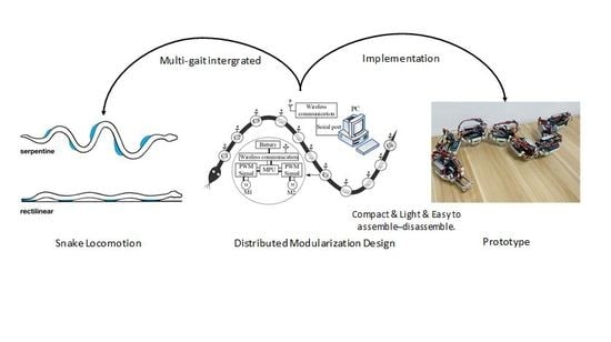
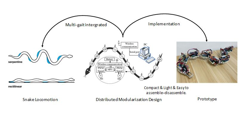
1. Introduction
2. Methods
2.1. Gait Analysis
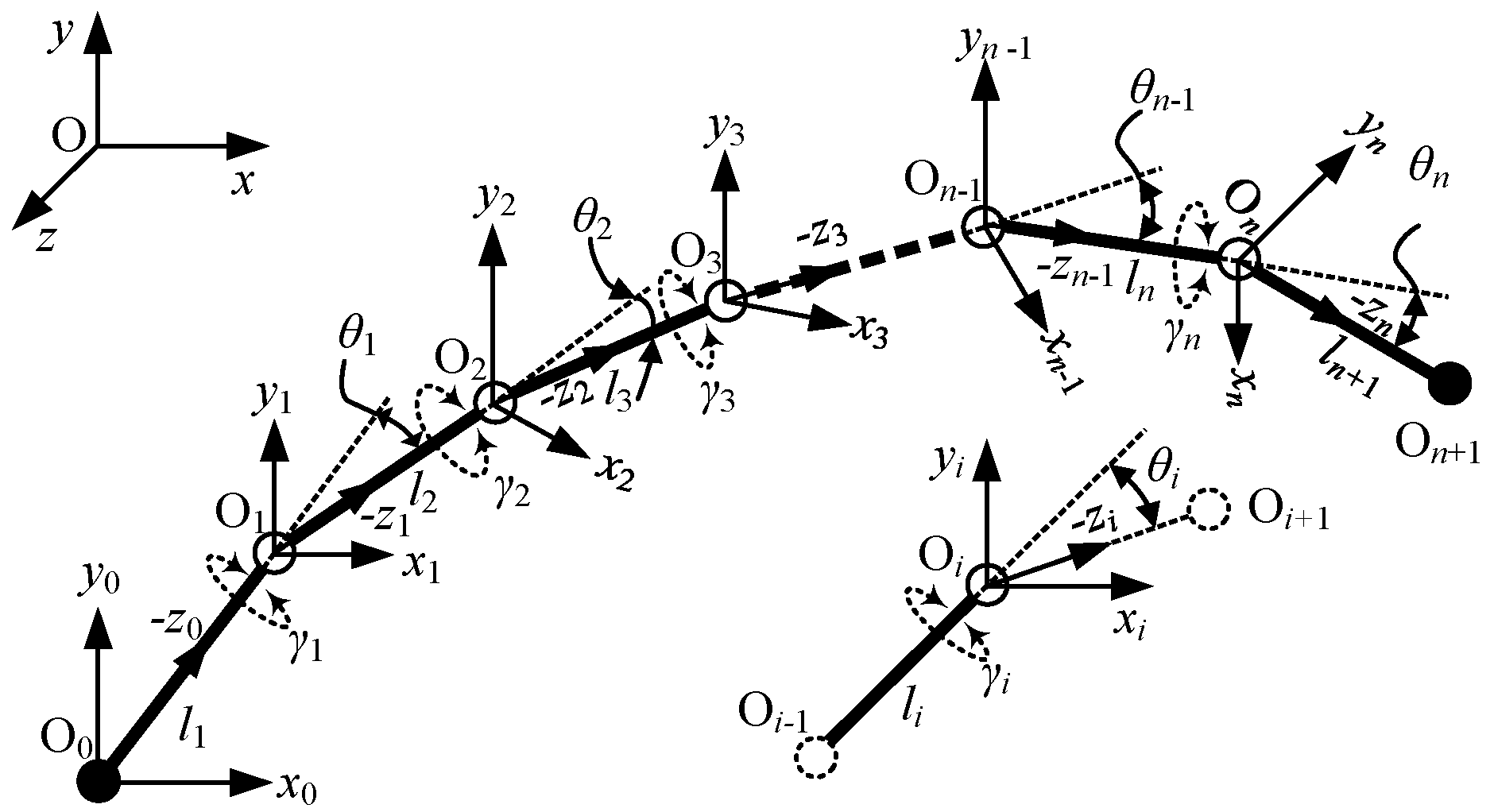
2.2. Kinematics of Locomotion Gaits
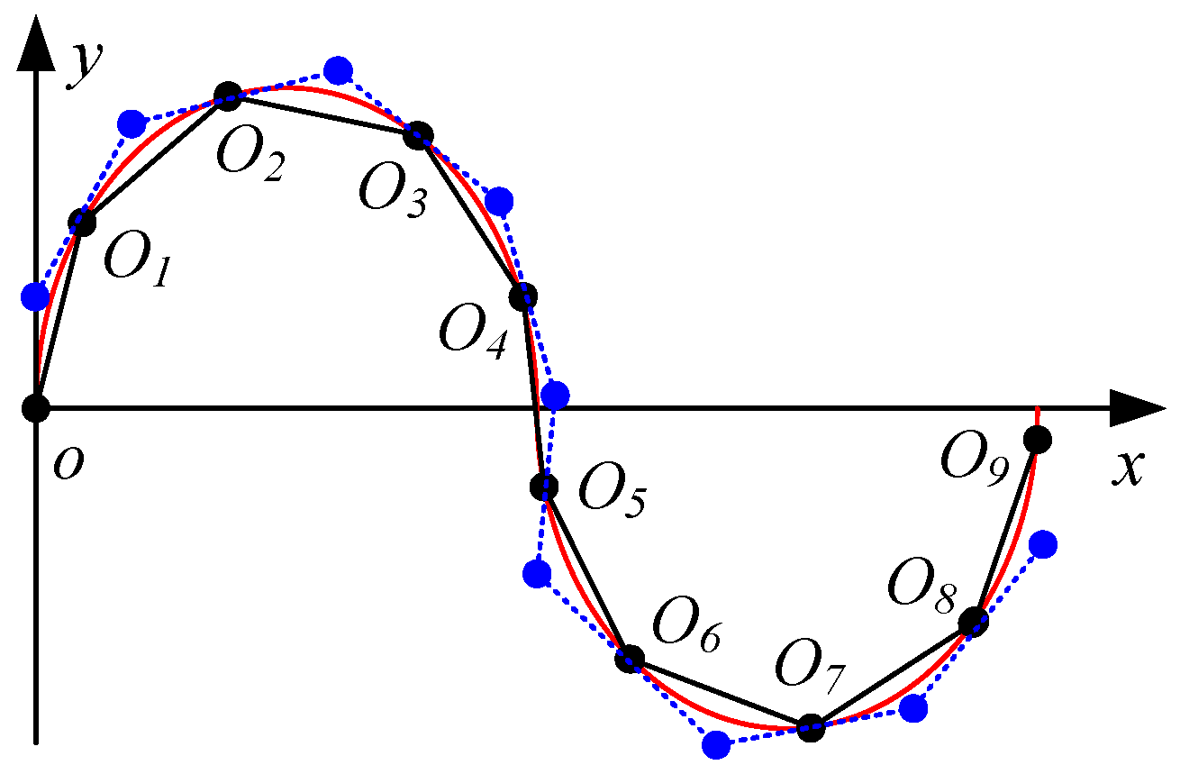
2.2.1. Serpentine Gait
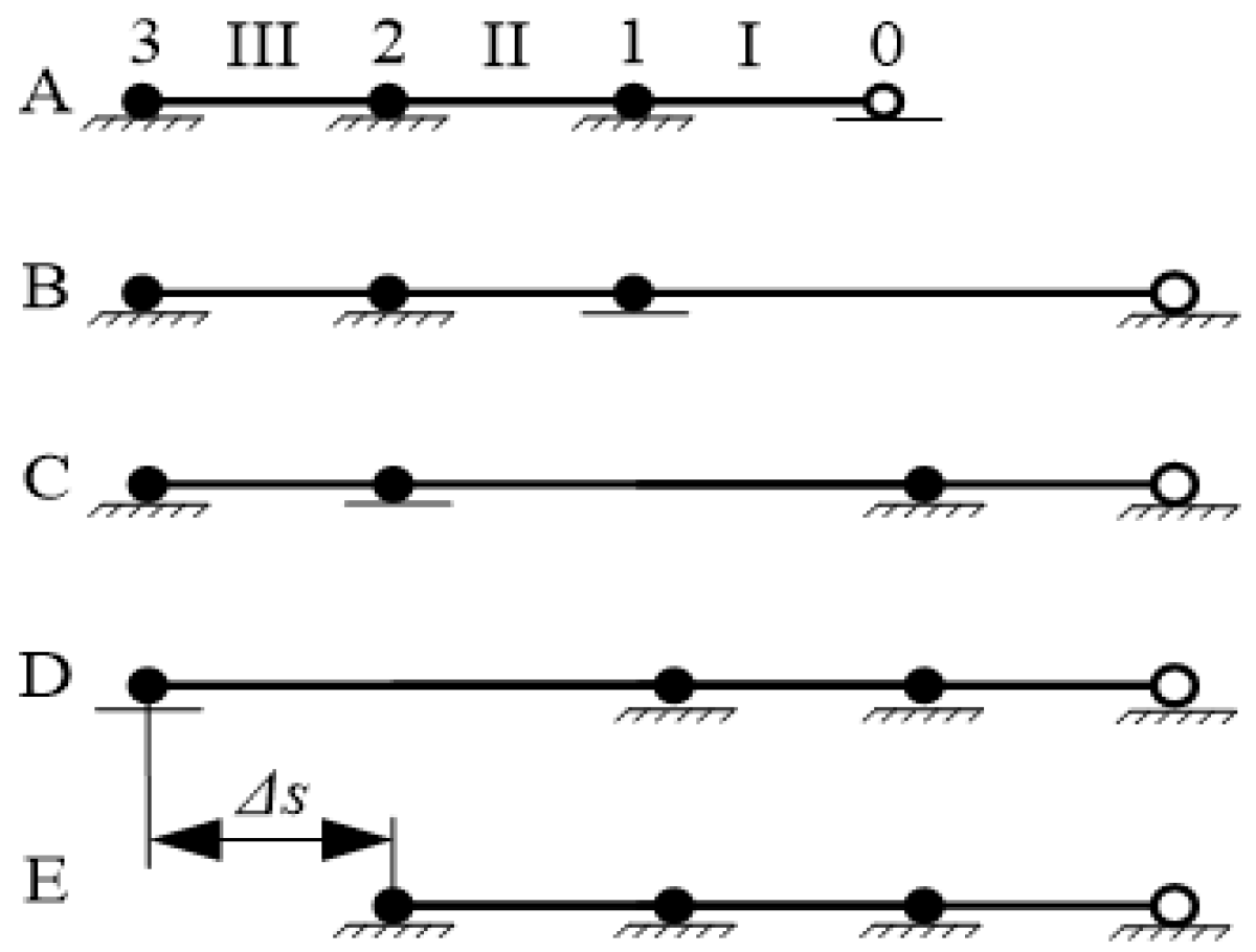
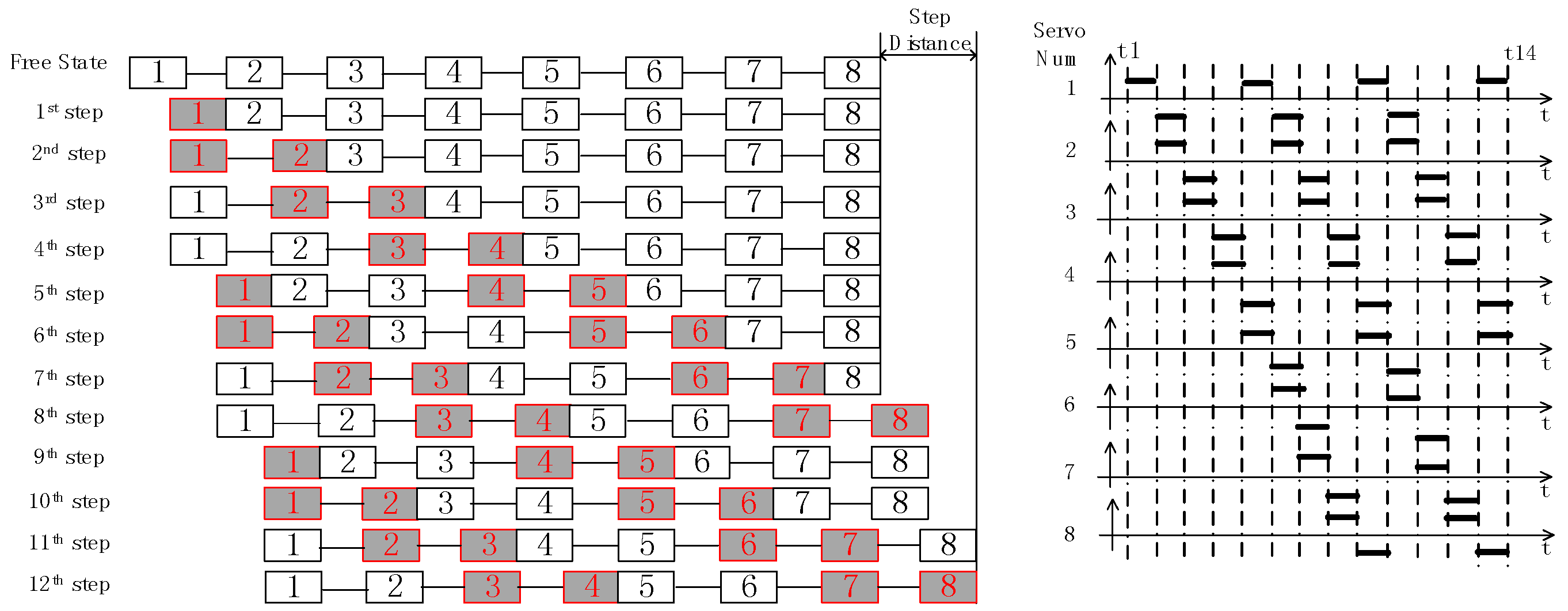
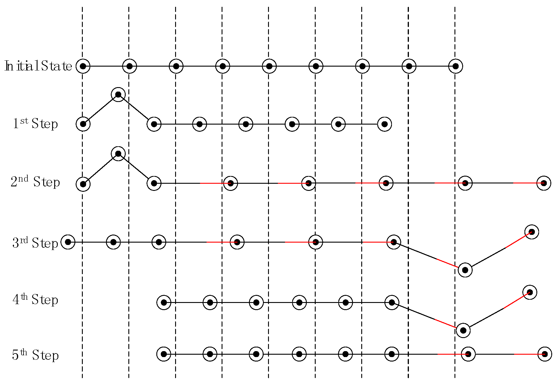
2.2.2. Rectilinear Gait
2.2.3. Obstacle-Aided Locomotion
2.3. Articulation Modular Design
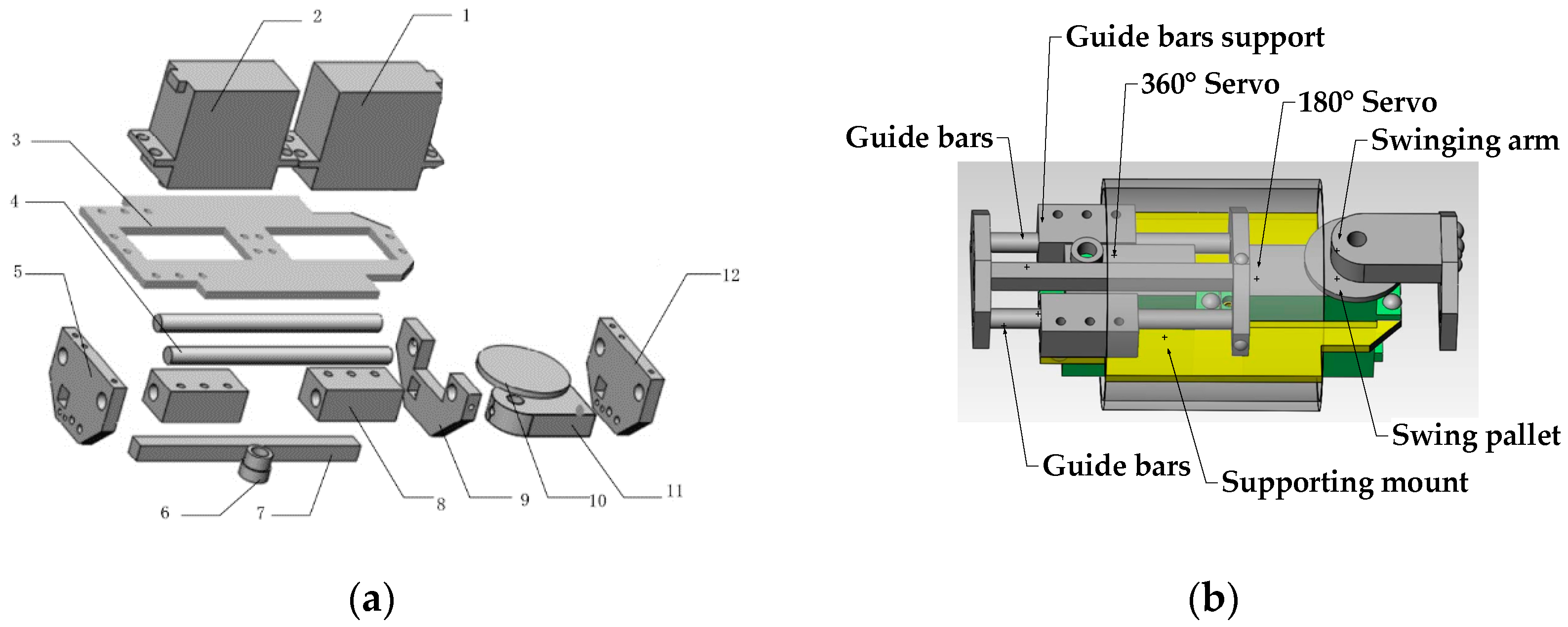
2.3.1. Joint Mechanism
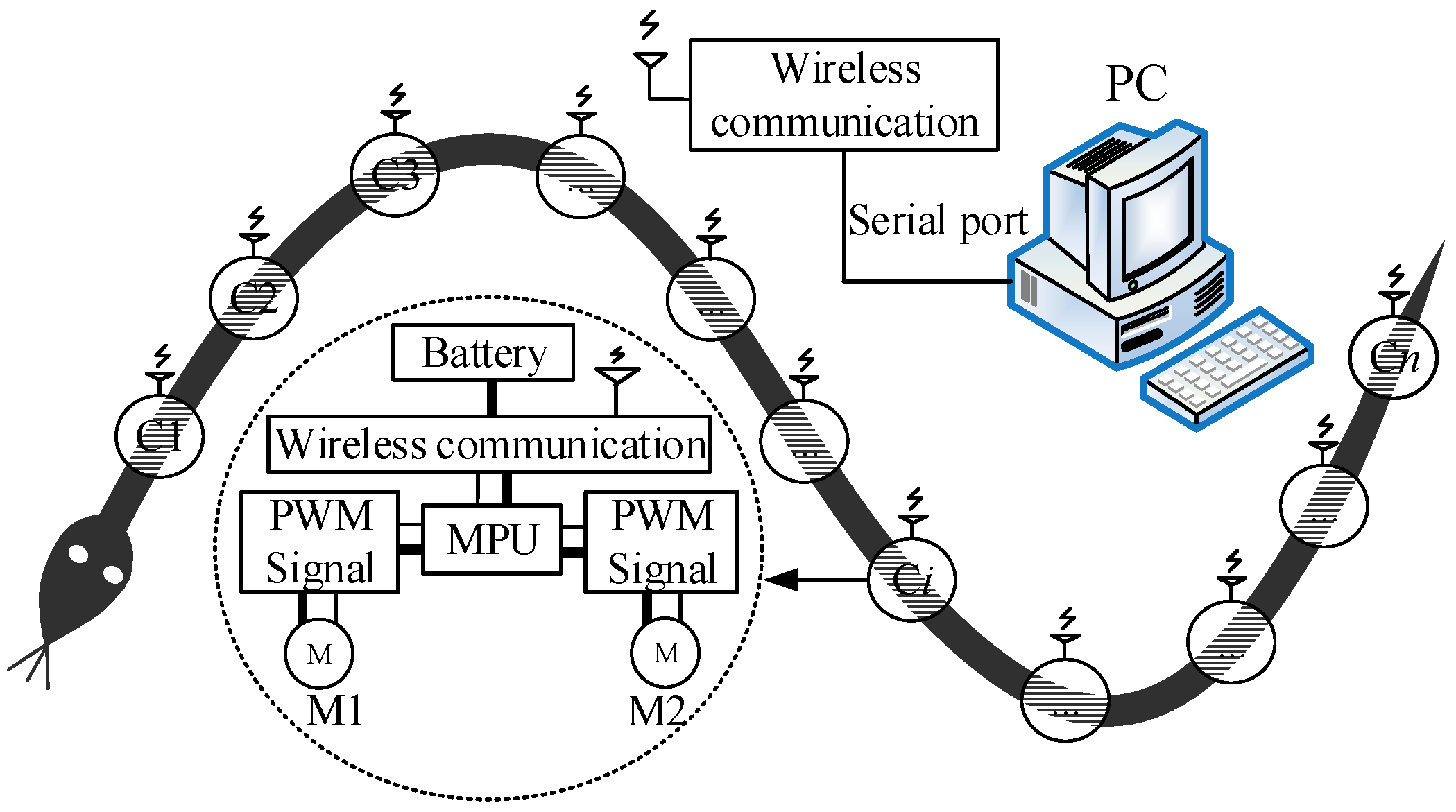
2.3.2. Electrical System
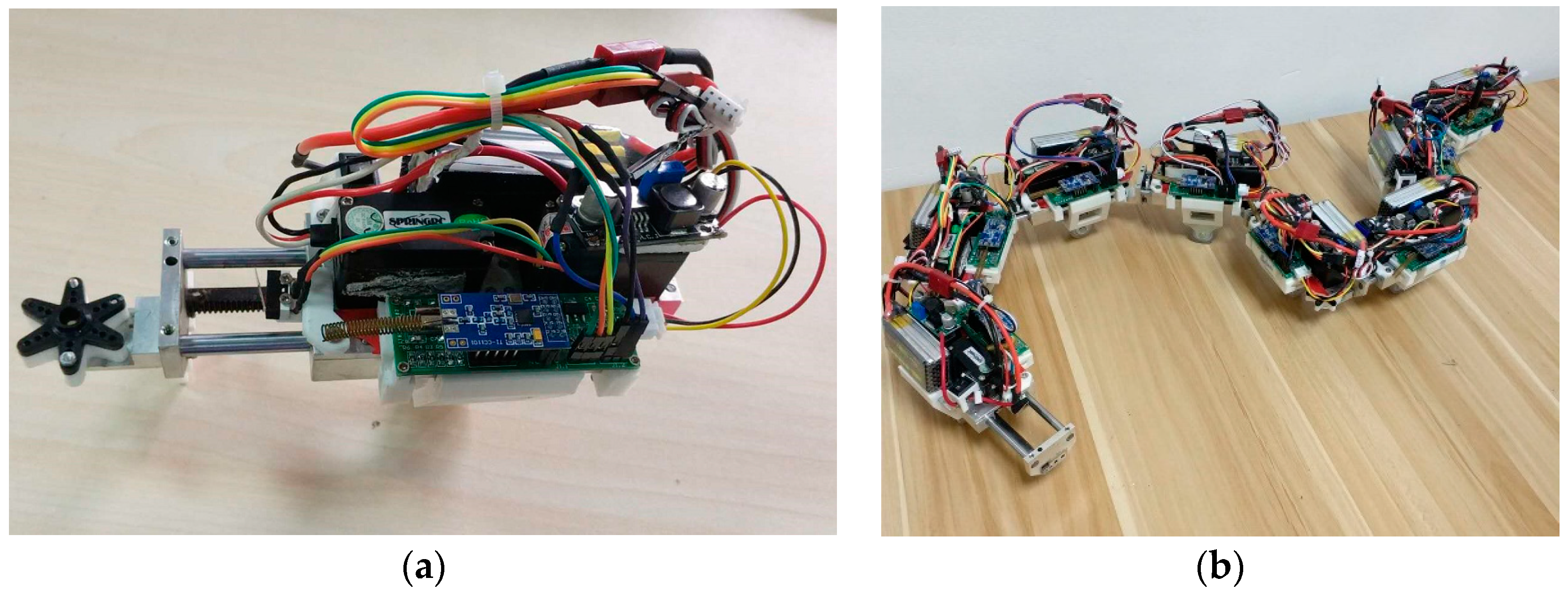
2.3.3. Articulation Module and Prototype
2.3.4. Control System
Serpentine Locomotion
Rectilinear Locomotion
3. Experiment and Results
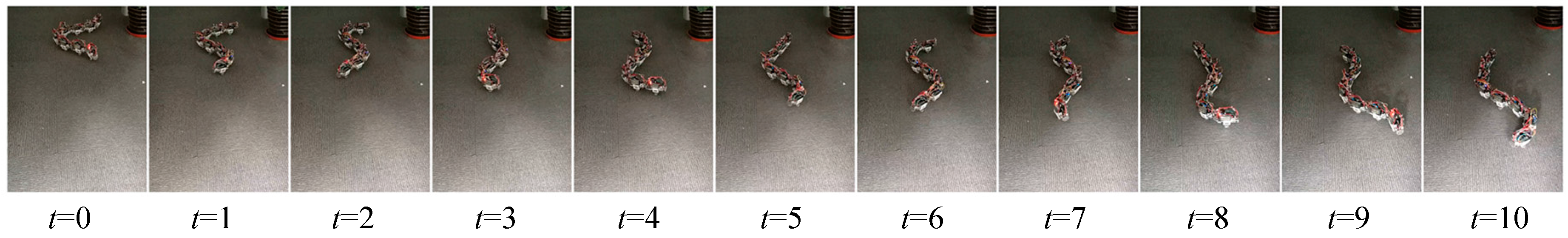
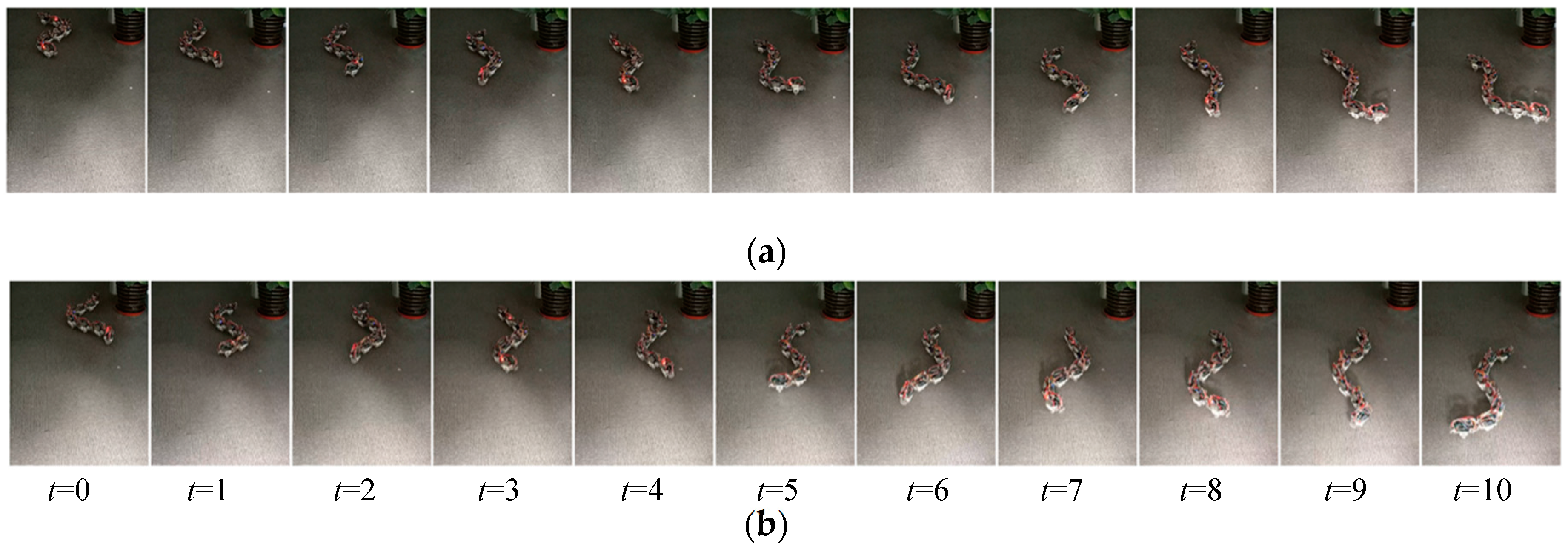
3.1. Serpentine Movement
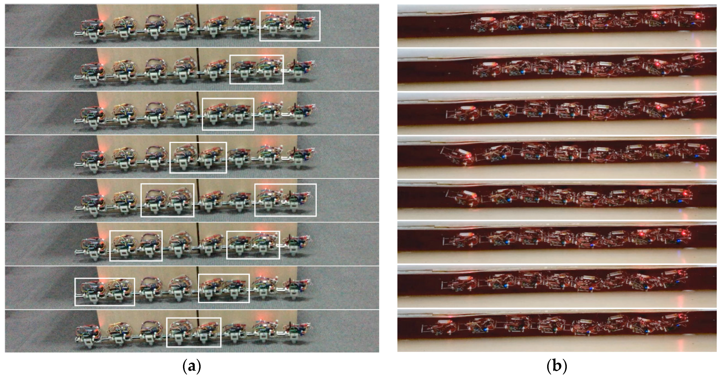
3.2. Rectilinear Locomotion and Its Fusion Gaits
4. Conclusions and Discussion
Supplementary Materials
Acknowledgments
Author Contributions
Conflicts of Interest
References
- Xuesu, X.; Cappo, E.; Weikun, Z.; Jin, D.; Ke, S.; Chaohui, G.; Travers, M.; Choset, H. Locomotive reduction for snake robots. In Proceedings of the 2015 IEEE International Conference on Robotics and Automation (ICRA), Seattle, WA, USA, 26–30 May 2015. [Google Scholar]
- Neumann, M.; Predki, T.; Heckes, L.; Labenda, P. Snake-like, tracked, mobile robot with active flippers for urban search-and-rescue tasks. Ind. Robot Int. J. 2013, 40, 246–250. [Google Scholar] [CrossRef]
- Liljebäck, P.; Pettersen, K.; Stavdahl, Ø.; Gravdahl, J. A review on modelling, implementation, and control of snake robots. Robot. Auton. Syst. 2012, 60, 29–40. [Google Scholar] [CrossRef] [Green Version]
- Hirose, S.; Yamada, H. Snake-Like Robots Machine Design of Biologically Inspired Robots. IEEE Robot. Autom. Mag. 2009, 16, 88–98. [Google Scholar] [CrossRef]
- Ma, S.; Tadokoro, N.; Inoue, K. Influence of the gradient of a slope on optimal locomotion curves of a snake-like robot. Adv. Robot. 2006, 20, 413–428. [Google Scholar] [CrossRef]
- Ye, C.; Ma, S.; Li, B.; Liu, H.; Wang, H. Development of a 3D Snake-like Robot: Perambulator-II. In Proceedings of the 2007 International Conference on Mechatronics and Automation, Harbin, China, 5–8 August 2007. [Google Scholar]
- Bayraktaroglu, Z. Snake-like locomotion: Experimentations with a biologically inspired wheel-less snake robot. Mech. Mach. Theory 2009, 44, 591–602. [Google Scholar] [CrossRef]
- Transeth, A.; Leine, R.; Glocker, C.; Pettersen, K.; Liljeback, P. Snake Robot Obstacle-Aided Locomotion: Modeling, Simulations, and Experiments. IEEE Trans. Robot. 2008, 24, 88–104. [Google Scholar] [CrossRef]
- Kuwada, A.; Wakimoto, S.; Suzumori, K.; Adomi, Y. Automatic pipe negotiation control for snake-like robot. In Proceedings of the 2008 IEEE/ASME International Conference on Advanced Intelligent Mechatronics, Xian, China, 2–5 July 2008. [Google Scholar]
- Crespi, A.; Ijspeert, A. Online Optimization of Swimming and Crawling in an Amphibious Snake Robot. IEEE Trans. Robot. 2008, 24, 75–87. [Google Scholar] [CrossRef]
- Klaassen, B.; Paap, K. GMD-SNAKE2: A snake-like robot driven by wheels and a method for motion control. In Proceedings of the 1999 IEEE International Conference on Robotics and Automation (Cat. No.99CH36288C), Detroit, MI, USA, 10–15 May 1999. [Google Scholar]
- Mori, M.; Hirose, S. Locomotion of 3D Snake-Like Robots—Shifting and Rolling Control of Active Cord Mechanism ACM-R3. J. Robot. Mechatron. 2006, 18, 521–528. [Google Scholar] [CrossRef]
- Shumei, Y.; Shugen, M.; Bin, L.; Yuechao, W. Analysis of helical gait of a snake-like robot. In Proceedings of the 2008 IEEE/ASME International Conference on Advanced Intelligent Mechatronics, Xian, China, 2–5 July 2008. [Google Scholar]
- Wang, K.; Ma, S. Analysis to Serpentine Locomotion Efficiency of Snake-like Robot. Abstr. Int. Conf. Adv. Mechatron. 2010, 5, 43–48. [Google Scholar] [CrossRef]
- Wang, K.; Ma, S. Kinematic analysis of snake-like robot using sliding joints. In Proceedings of the 2010 IEEE International Conference on Robotics and Biomimetics, Tianjin, China, 14–18 December 2010. [Google Scholar]
- Sanfilippo, F.; Azpiazu, J.; Marafioti, G.; Transeth, A.; Stavdahl, Y.; Liljebäck, P. Perception-Driven Obstacle-Aided Locomotion for Snake Robots: The State of the Art, Challenges and Possibilities. Appl. Sci. 2017, 7, 336. [Google Scholar] [CrossRef]


| Labels | Part Name | Properties |
|---|---|---|
| 1 | Servo 1 | |
| 2 | Servo 2 | 360° |
| 3 | Supporting mount | Aluminum alloy |
| 4 | Guide bars | Carbon steel |
| 5 | Left end cover | Aluminum alloy |
| 6 | Gear | Alloy steel, 0.5 module, 20 teeth |
| 7 | Rack | Alloy steel, 0.5 module, 6 mm height and width |
| 8 | Guide bars support | Aluminum alloy |
| 9 | Right end cover | Aluminum alloy |
| 10 | Swing pallet | Plastic |
| 11 | Swinging arm | Aluminum alloy |
| 12 | End cover of joint | Aluminum alloy |
| Number of Module | 7 |
|---|---|
| Overall length (mm) | 1280 |
| Individual module diameter | 70 |
| Single module quality (g) | 350 |
| Joint rotation angle | −60°–60° |
| Step distance of linear translational joint (mm) | 34.4 |
| Time (s) | 0 | 1 | 2 | 3 | 4 | 5 | 6 | 7 | 8 |
|---|---|---|---|---|---|---|---|---|---|
| Rotation angle | −42 | −13 | 24 | 47 | 42 | 13 | −24 | −47 | −42 |
© 2017 by the authors. Licensee MDPI, Basel, Switzerland. This article is an open access article distributed under the terms and conditions of the Creative Commons Attribution (CC BY) license (http://creativecommons.org/licenses/by/4.0/).
Share and Cite
Wang, K.; Gao, W.; Ma, S. Snake-Like Robot with Fusion Gait for High Environmental Adaptability: Design, Modeling, and Experiment. Appl. Sci. 2017, 7, 1133. https://doi.org/10.3390/app7111133
Wang K, Gao W, Ma S. Snake-Like Robot with Fusion Gait for High Environmental Adaptability: Design, Modeling, and Experiment. Applied Sciences. 2017; 7(11):1133. https://doi.org/10.3390/app7111133
Chicago/Turabian StyleWang, Kundong, Wencan Gao, and Shugen Ma. 2017. "Snake-Like Robot with Fusion Gait for High Environmental Adaptability: Design, Modeling, and Experiment" Applied Sciences 7, no. 11: 1133. https://doi.org/10.3390/app7111133
APA StyleWang, K., Gao, W., & Ma, S. (2017). Snake-Like Robot with Fusion Gait for High Environmental Adaptability: Design, Modeling, and Experiment. Applied Sciences, 7(11), 1133. https://doi.org/10.3390/app7111133