Experimental Study on Vibration Control of a Submerged Pipeline Model by Eddy Current Tuned Mass Damper


Abstract
:1. Introduction
2. Effectiveness of Eddy Current Damping in Seawater
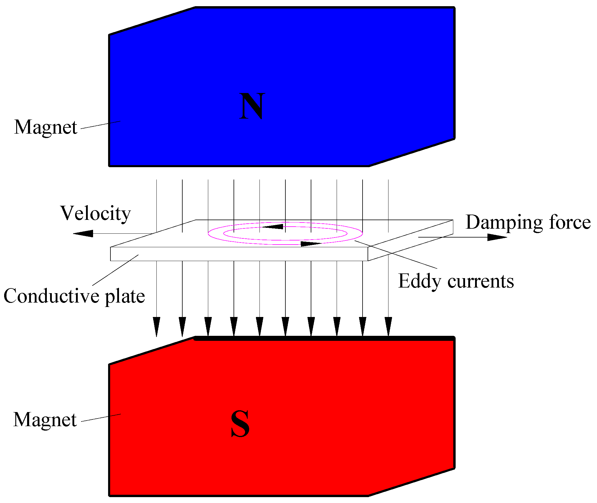
2.1. Eddy Current Damping
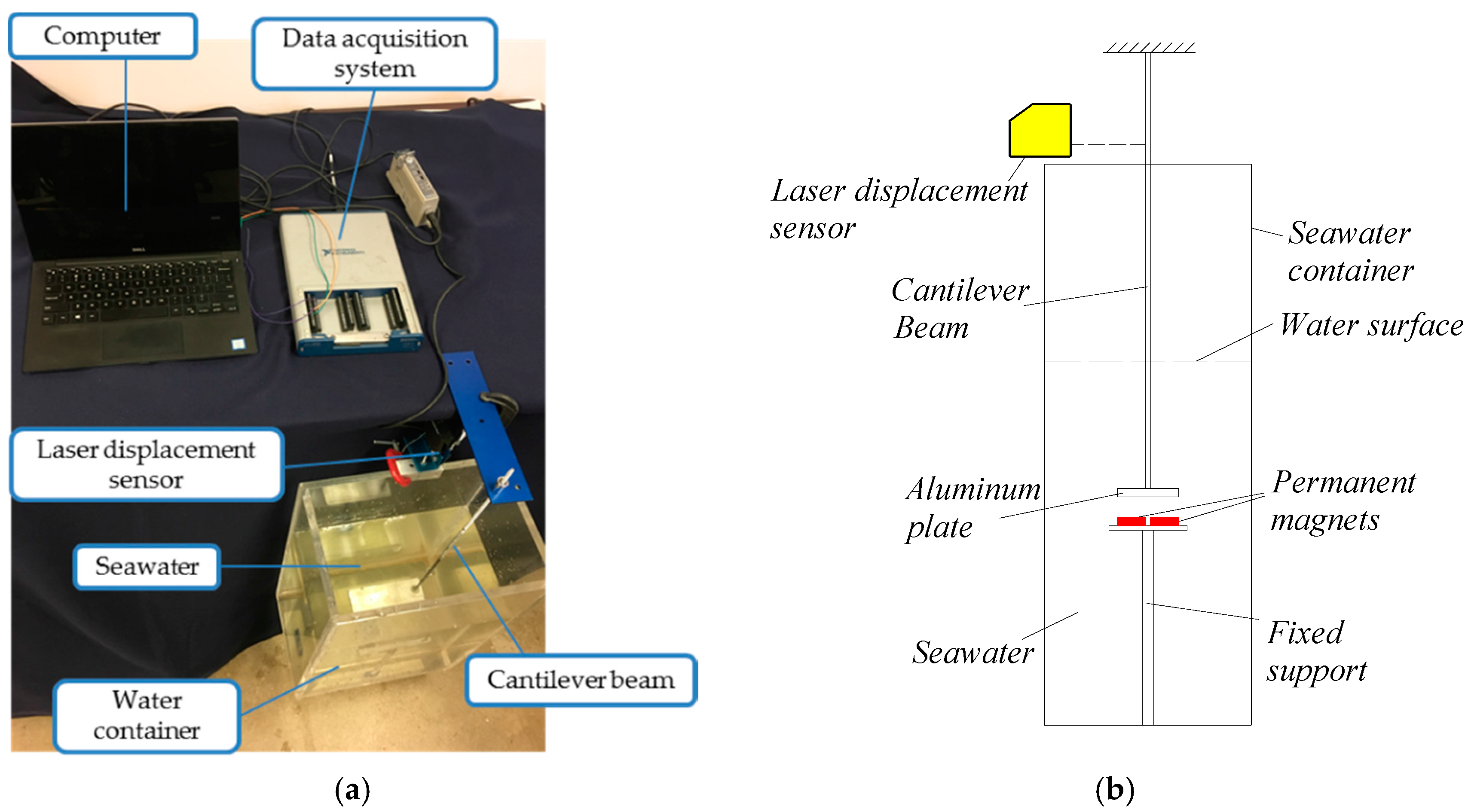
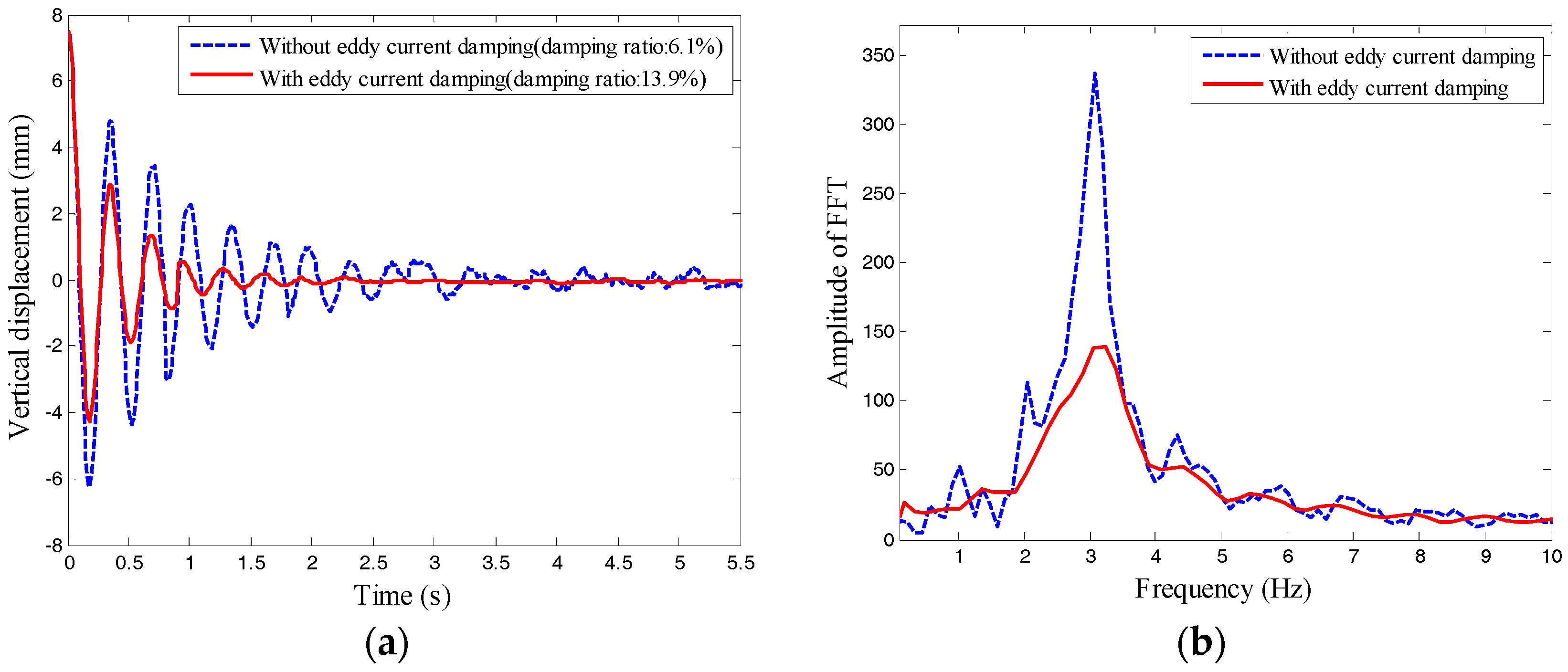
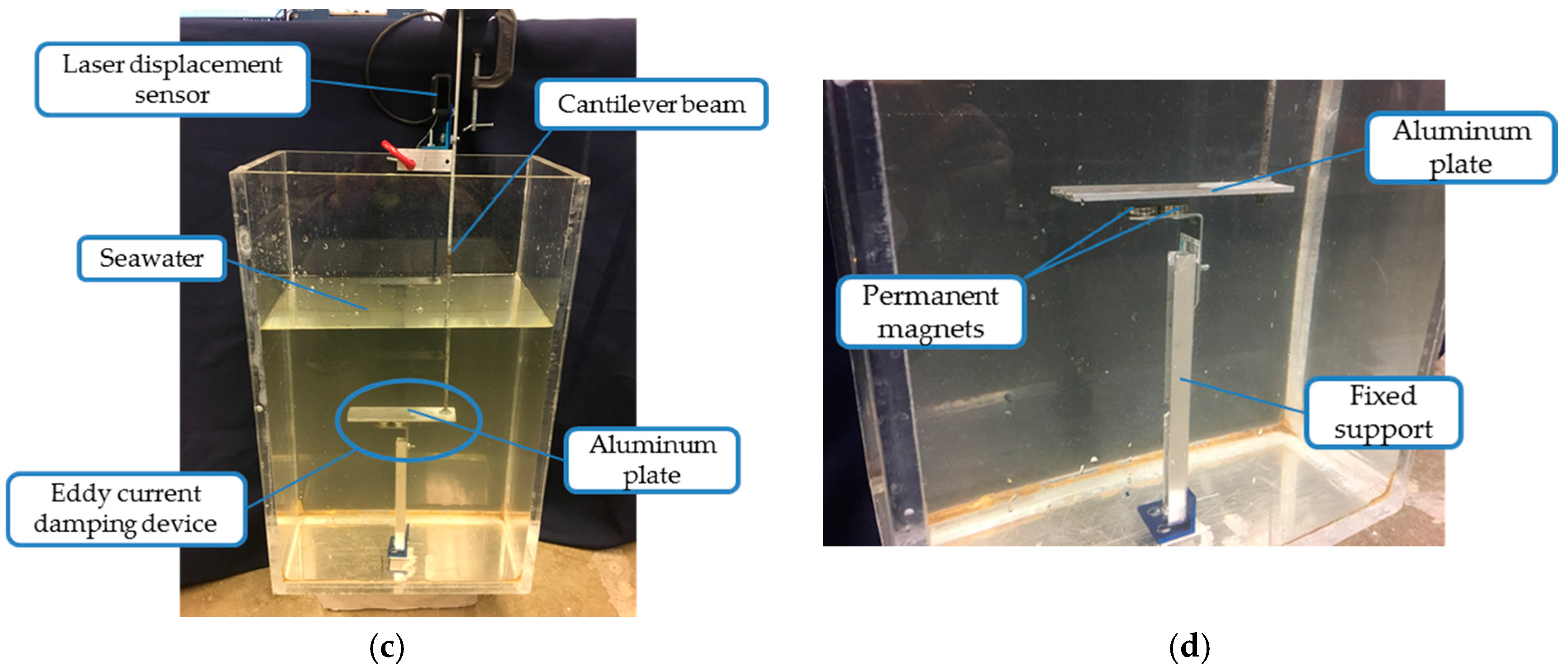
2.2. Free Vibration Tests of a Eddy Current Damper in Seawater Environment
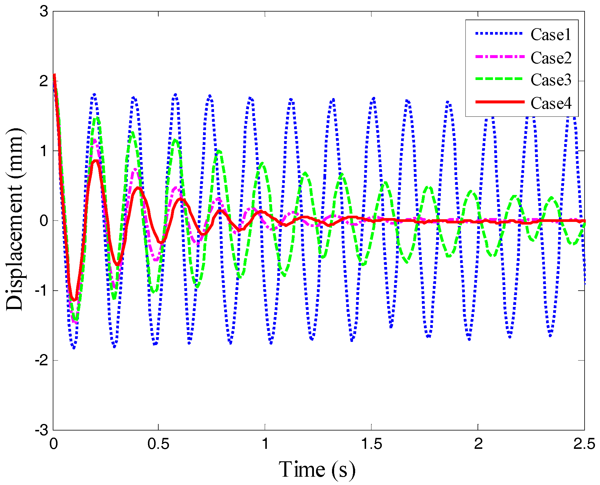
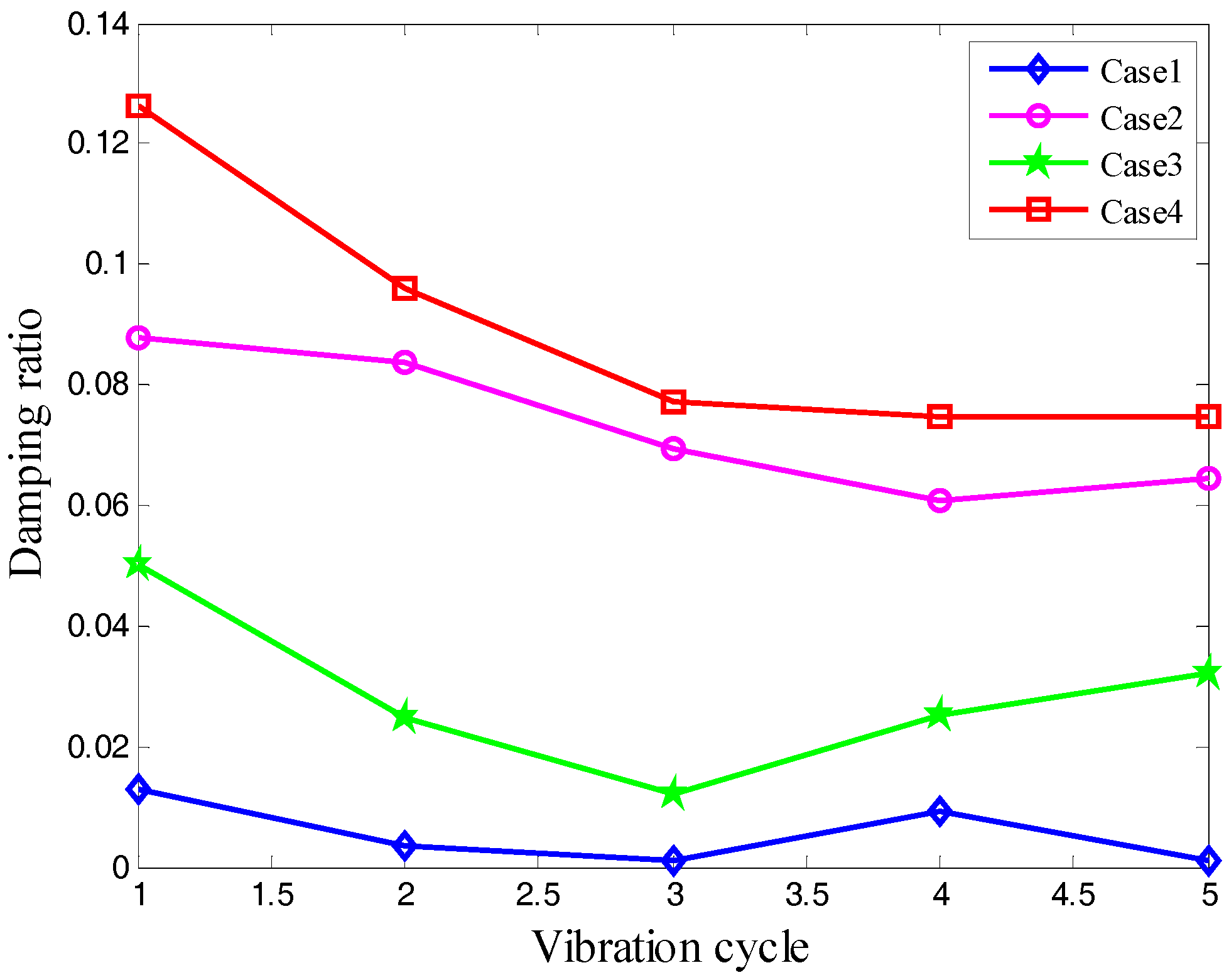
2.3. Experimental Results
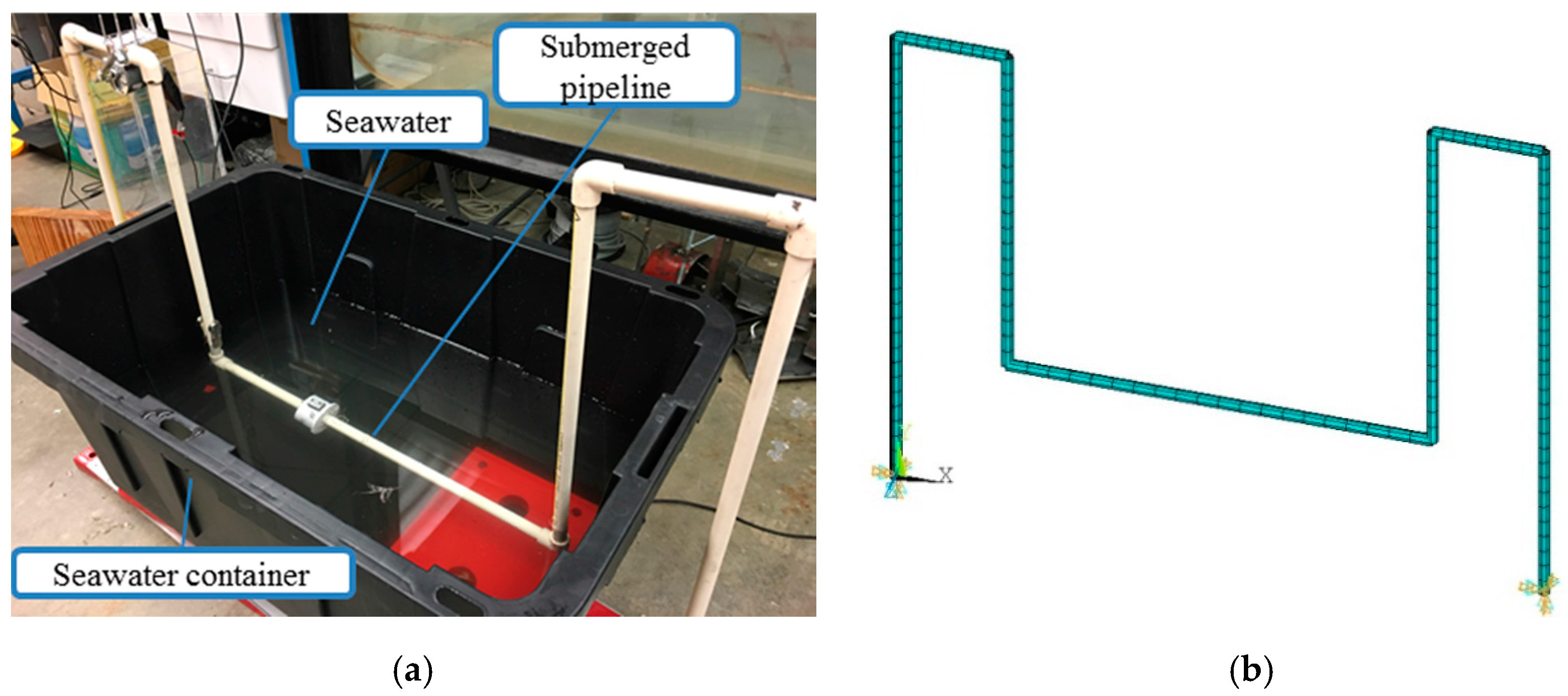
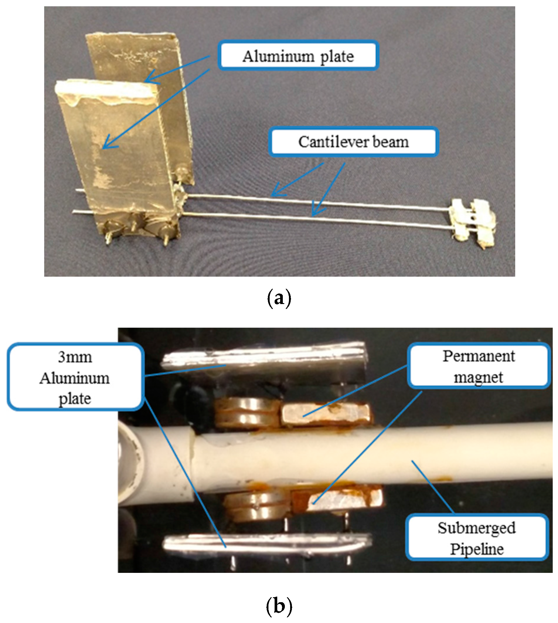
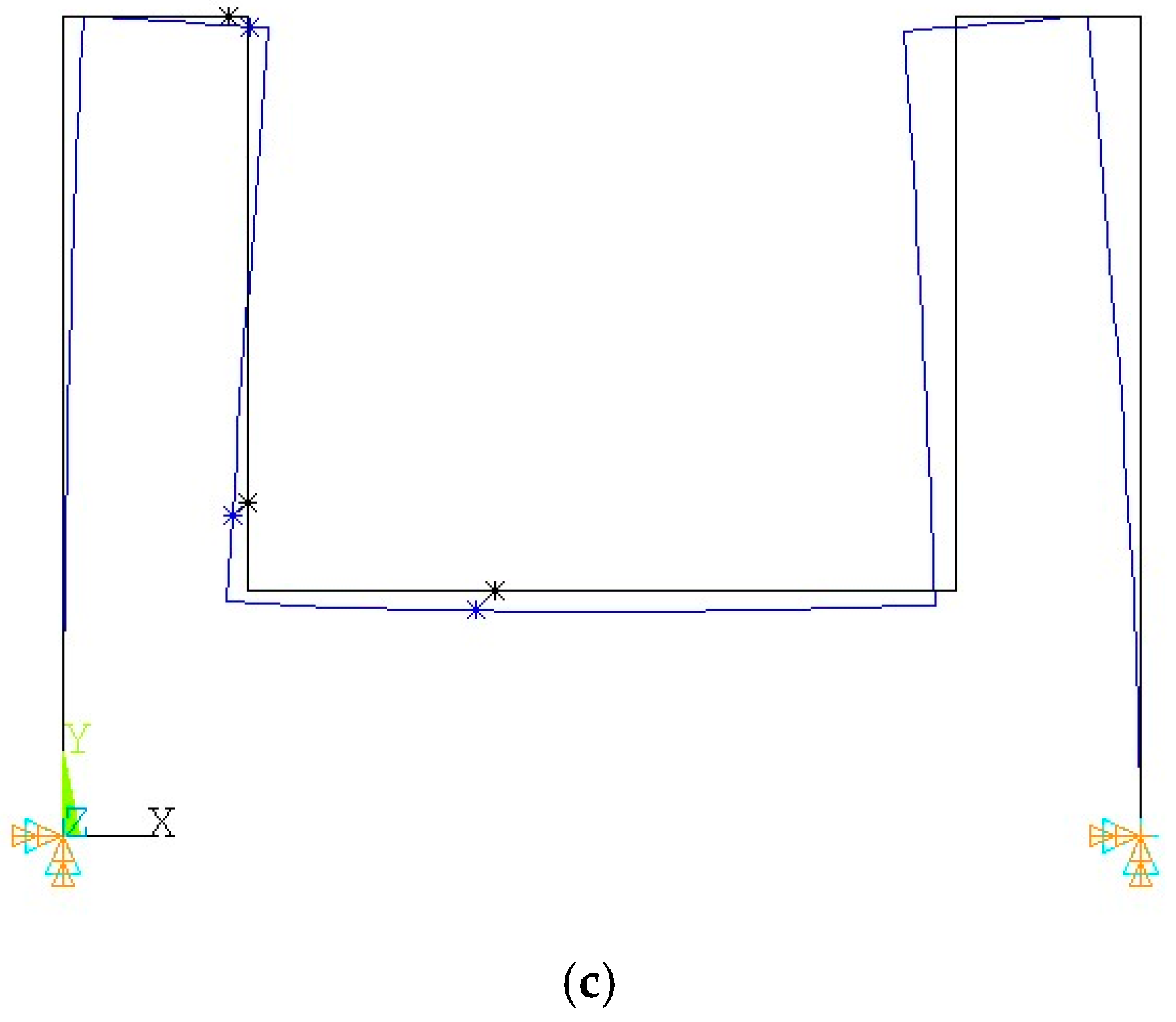
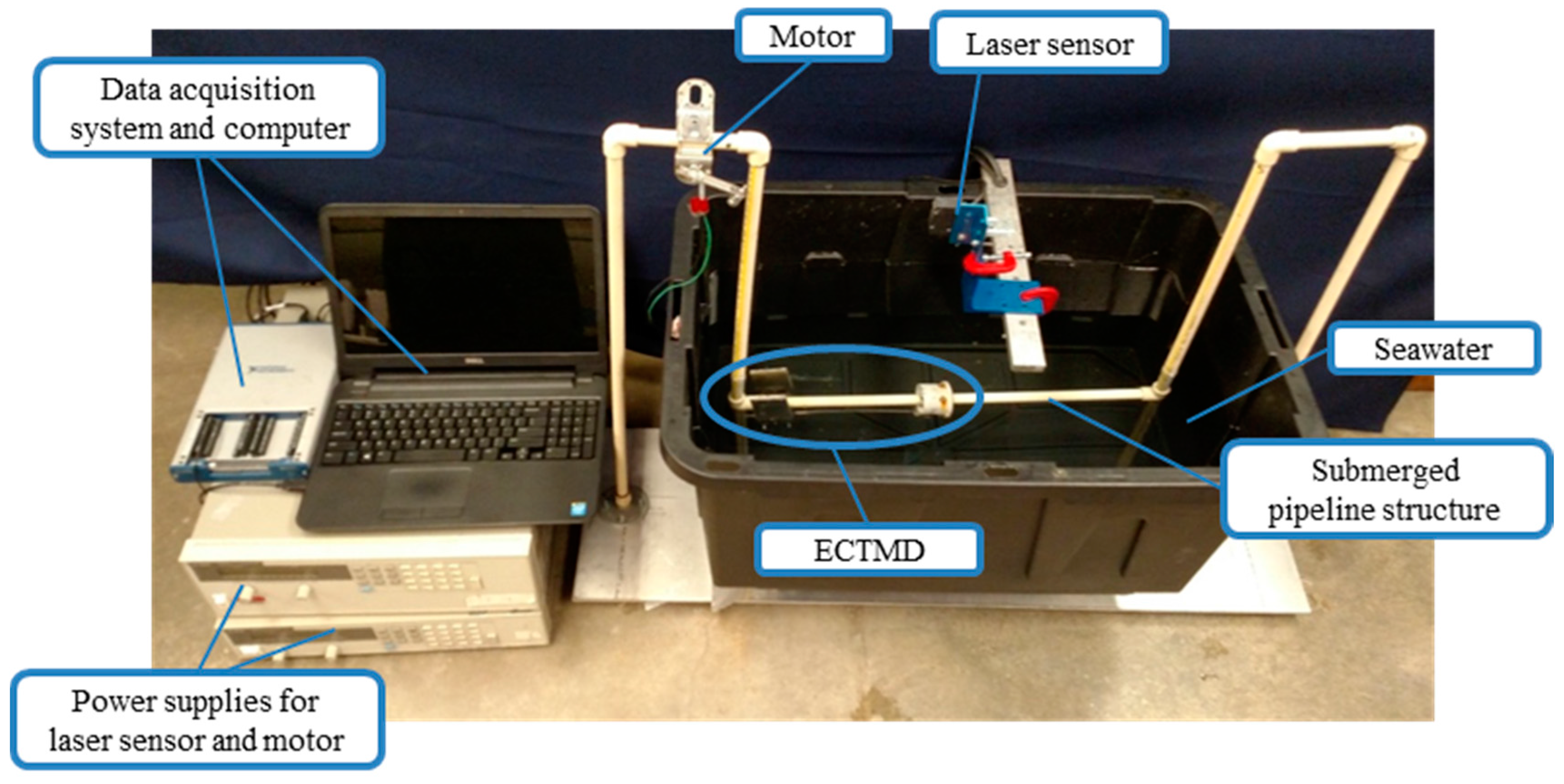
3. Experimental Model of a Submerged Pipeline
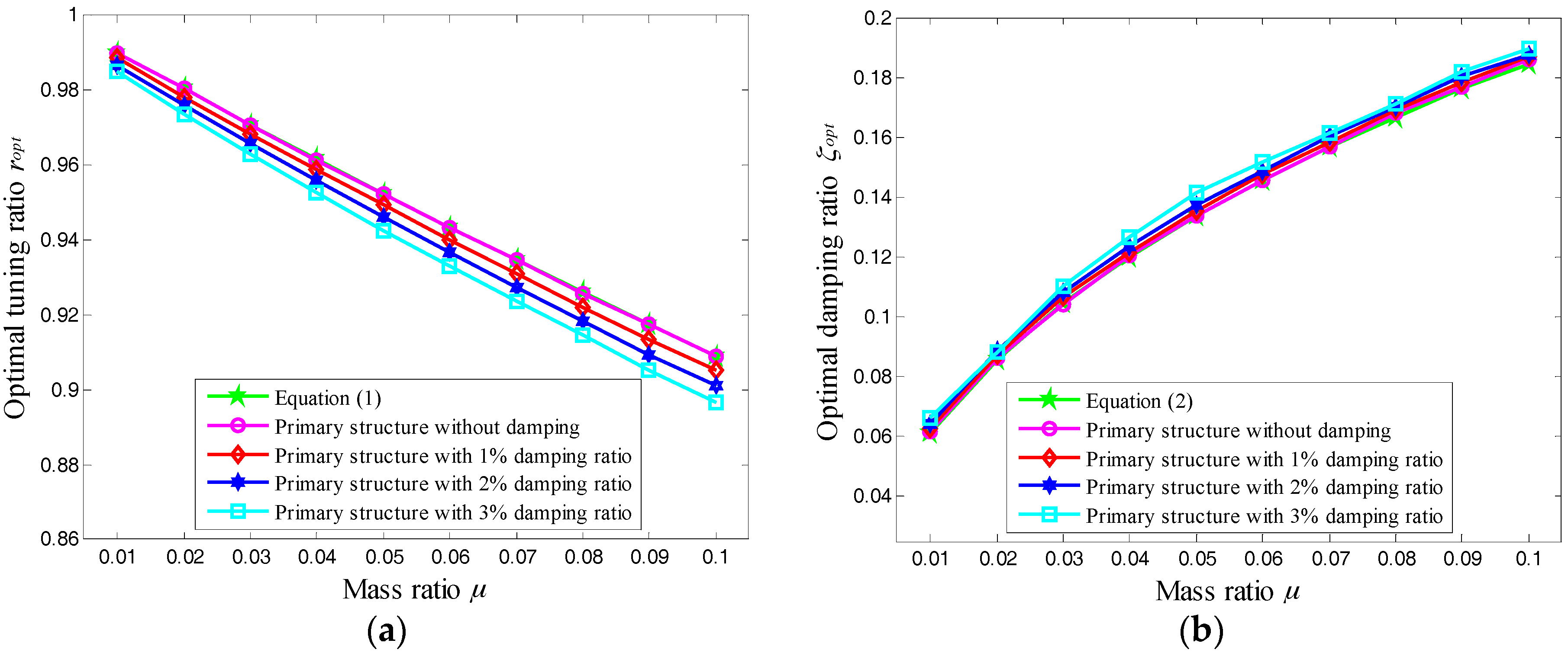
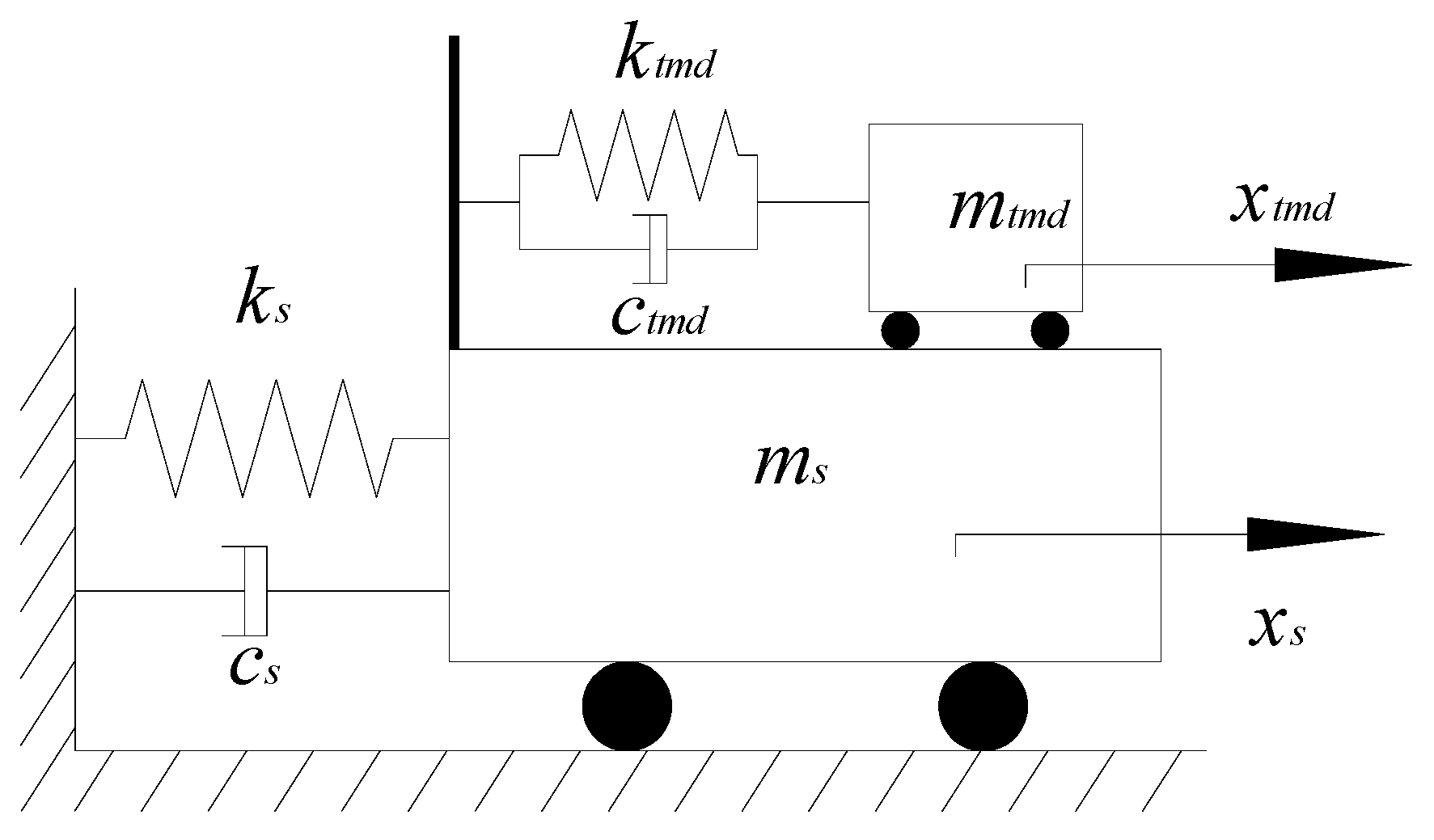
4. Optimal Design of ECTMD for Damped Structure
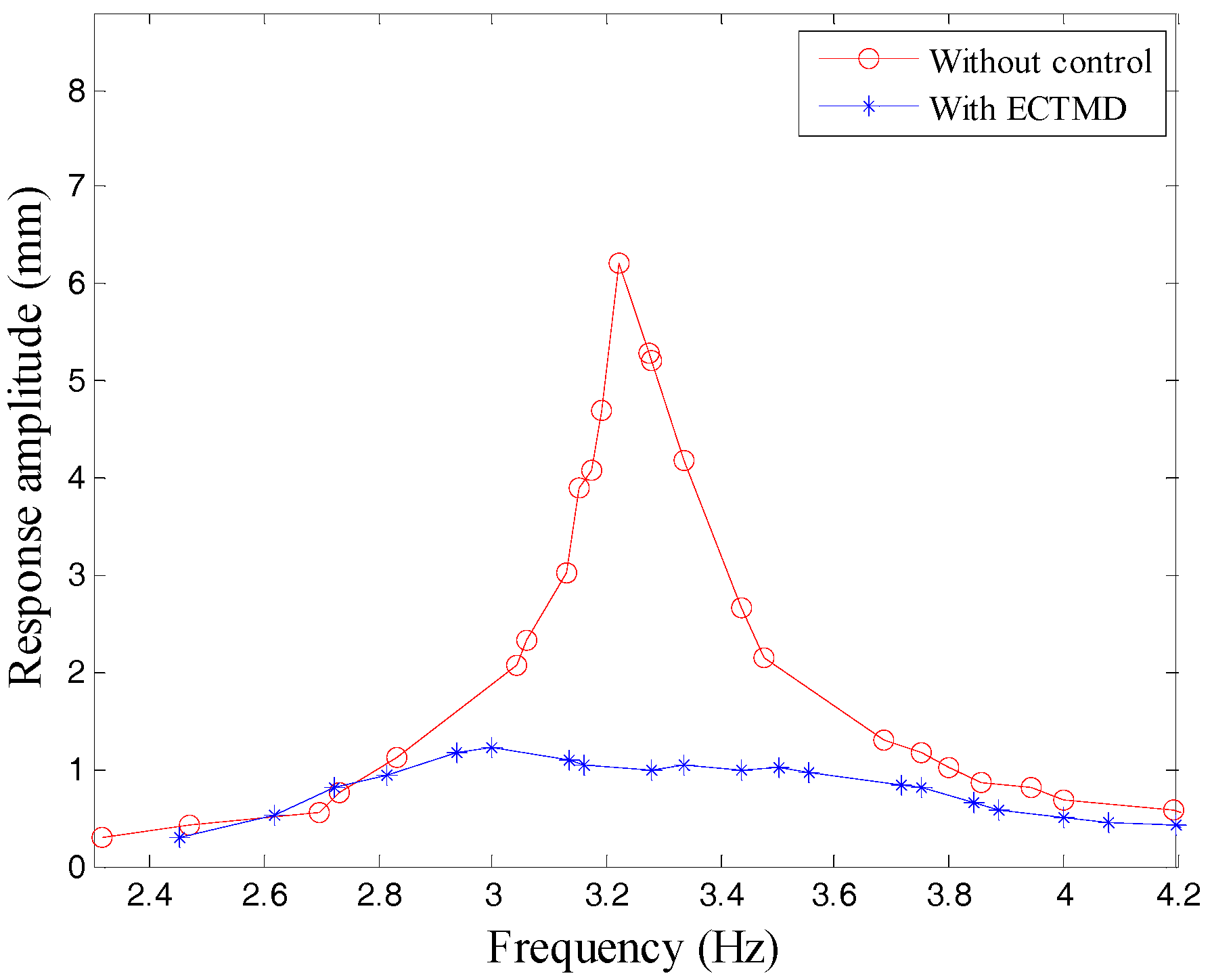
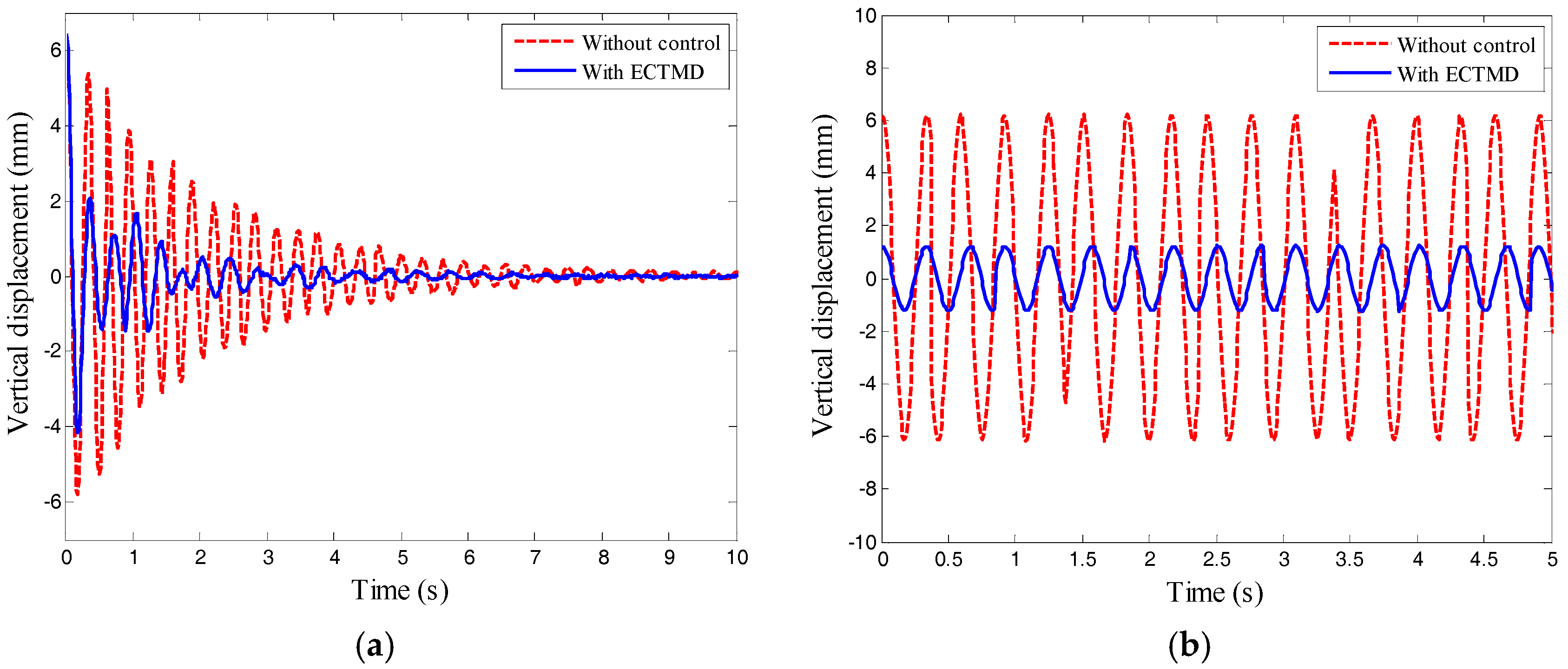
5. Effectiveness of ECTMD to Control a Submerged Pipeline
6. Conclusions
Acknowledgments
Author Contributions
Conflicts of Interest
References
- Lu, Z.; Masri, S.F.; Lu, X. Parametric studies of the performance of particle dampers under harmonic excitation. Struct. Control Health Monit. 2011, 18, 79–98. [Google Scholar] [CrossRef]
- Lu, Z.; Masri, S.F.; Lu, X. Studies of the performance of particle dampers attached to a two-degrees-of-freedom system under random excitation. J. Vib. Control 2011, 17, 1454–1471. [Google Scholar]
- Tian, L.; Rong, K.; Zhang, P.; Liu, Y. Vibration control of a power transmission tower with pounding tuned mass damper under multi-component seismic excitations. Appl. Sci. 2017, 7, 477. [Google Scholar] [CrossRef]
- Li, H.; Liu, M.; Li, J.; Guan, X.; Ou, J. Vibration control of stay cables of the shandong binzhou yellow river highway bridge using magnetorheological fluid dampers. J. Bridge Eng. 2007, 12, 401–409. [Google Scholar] [CrossRef]
- Cai, C.S.; Wu, W.J.; Araujo, M. Cable vibration control with a TMD-MR damper system: Experimental exploration. J. Struct. Eng. 2007, 133, 629–637. [Google Scholar] [CrossRef]
- Jiang, J.; Zhang, P.; Patil, D.; Li, H.; Song, G. Experimental studies on the effectiveness and robustness of a pounding tuned mass damper for vibration suppression of a submerged cylindrical pipe. Struct. Control Health Monit. 2017, e2027. [Google Scholar] [CrossRef]
- Fu, W.; Zhang, C.; Sun, L.; Askari, M.; Samali, B.; Chung, K.L.; Sharafi, P. Experimental investigation of a base isolation system incorporating MR dampers with the high-order single step control algorithm. Appl. Sci. 2017, 7, 344. [Google Scholar] [CrossRef]
- Biswas, S.K.; Ahmed, N.U. Optimal control of flow-induced vibration of pipeline. Dyn. Control 2001, 11, 187–201. [Google Scholar] [CrossRef]
- Frahm, H. Device for Damping Vibrations of Bodies. U.S. Patent 989958, 18 April 1911. [Google Scholar]
- Tao, T.; Wang, H.; Yao, C.; He, X. Parametric sensitivity analysis on the buffeting control of a long-span triple-tower suspension bridge with MTMD. Appl. Sci. 2017, 7, 395. [Google Scholar] [CrossRef]
- Li, C. Performance of multiple tuned mass dampers for attenuating undesirable oscillations of structures under the ground acceleration. Earthq. Eng. Struct. Dyn. 2000, 29, 1405–1421. [Google Scholar] [CrossRef]
- Varadarajan, N.; Nagarajaiah, S. Wind response control of building with variable stiffness tuned mass damper using empirical mode decomposition/Hilbert transform. J. Eng. Mech. 2004, 130, 451–458. [Google Scholar] [CrossRef]
- Setareh, M.; Hanson, R.D. Tuned mass dampers to control floor vibration from humans. J. Struct. Eng. 1992, 118, 741–762. [Google Scholar] [CrossRef]
- Caetano, E.; Cunha, Á.; Magalhães, F.; Moutinho, C. Studies for controlling human-induced vibration of the Pedro e Inês footbridge, Portugal. Part 1: Assessment of dynamic behaviour. Eng. Struct. 2010, 32, 1069–1081. [Google Scholar] [CrossRef]
- Caetano, E.; Cunha, Á.; Moutinho, C.; Magalhães, F. Studies for controlling human-induced vibration of the Pedro e Inês footbridge, Portugal. Part 2: Implementation of tuned mass dampers. Eng. Struct. 2010, 32, 1082–1091. [Google Scholar] [CrossRef]
- Sims, N.D. Vibration absorbers for chatter suppression: A new analytical tuning methodology. J. Sound Vib. 2007, 301, 592–607. [Google Scholar] [CrossRef]
- Yang, Y.; Munoa, J.; Altintas, Y. Optimization of multiple tuned mass dampers to suppress machine tool chatter. Int. J. Mach. Tools Manuf. 2010, 50, 834–842. [Google Scholar] [CrossRef]
- Wang, M.; Zan, T.; Yang, Y.; Fei, R. Design and implementation of nonlinear TMD for chatter suppression: An application in turning processes. Int. J. Mach. Tools Manuf. 2010, 50, 474–479. [Google Scholar] [CrossRef]
- Kim, S.M.; Wang, S.; Brennan, M.J. Optimal and robust modal control of a flexible structure using an active dynamic vibration absorber. Smart Mater. Struct. 2011, 20, 045003. [Google Scholar] [CrossRef]
- Weber, F. Semi-active vibration absorber based on real-time controlled MR damper. Mech. Syst. Signal Process. 2014, 46, 272–288. [Google Scholar] [CrossRef]
- Kwok, K.C.S.; Samali, B. Performance of tuned mass dampers under wind loads. Eng. Struct. 1995, 17, 655–667. [Google Scholar] [CrossRef]
- Hong, S.R.; Wang, G.; Hu, W.; Wereley, N.M. Liquid spring shock absorber with controllable magnetorheological damping. Proc. Inst. Mech. Eng. Part D 2006, 220, 1019–1029. [Google Scholar] [CrossRef]
- Wang, W.; Hua, X.; Wang, X.; Chen, Z.; Song, G. Optimum design of a novel pounding tuned mass damper under harmonic excitation. Smart Mater. Struct. 2017, 26, 055024. [Google Scholar] [CrossRef]
- Lu, Z.; Chen, X.; Zhang, D.; Dai, K. Experimental and analytical study on the performance of particle tuned mass dampers under seismic excitation. Earthq. Eng. Struct. Dyn. 2017, 46, 697–714. [Google Scholar] [CrossRef]
- Koo, J.H.; Ahmadian, M.; Setareh, M. Experimental robustness analysis of magneto-rheological tuned vibration absorbers subject to mass off-tuning. J. Vib. Acoust. 2006, 128, 126–131. [Google Scholar] [CrossRef]
- Weber, F.; Maślanka, M. Frequency and damping adaptation of a TMD with controlled MR damper. Smart Mater. Struct. 2012, 21, 055011. [Google Scholar] [CrossRef]
- Sodano, H.A.; Bae, J.S.; Inman, D.J.; Belvin, W.K. Improved concept and model of eddy current damper. J. Vib. Acoust. 2006, 128, 294–302. [Google Scholar] [CrossRef]
- Sodano, H.A.; Inman, D.J.; Belvin, W.K. Development of a new passive-active magnetic damper for vibration suppression. J. Vib. Acoust. 2006, 128, 318–327. [Google Scholar] [CrossRef]
- Sodano, H.A.; Bae, J.S.; Inman, D.J.; Belvin, W.K. Concept and model of eddy current damper for vibration suppression of a beam. J. Sound Vib. 2005, 288, 1177–1196. [Google Scholar] [CrossRef]
- Bae, J.S.; Kwak, M.K.; Inman, D.J. Vibration suppression of a cantilever beam using eddy current damper. J. Sound Vib. 2005, 284, 805–824. [Google Scholar] [CrossRef]
- Wang, Z.; Chen, Z.; Wang, J. Feasibility study of a large-scale tuned mass damper with eddy current damping mechanism. Earthq. Eng. Eng. Vib. 2012, 11, 391–401. [Google Scholar] [CrossRef]
- Larose, G.L.; Larsen, A.; Svensson, E. Modelling of tuned mass dampers for wind-tunnel tests on a full-bridge aeroelastic model. J. Wind Eng. Ind. Aerodyn. 1995, 54, 427–437. [Google Scholar] [CrossRef]
- Bae, J.S.; Hwang, J.H.; Roh, J.H.; Kim, J.H.; Yi, M.S.; Lim, J.H. Vibration suppression of a cantilever beam using magnetically tuned-mass-damper. J. Sound Vib. 2012, 331, 5669–5684. [Google Scholar] [CrossRef]
- Bae, J.S.; Hwang, J.H.; Kwag, D.G.; Park, J.; Inman, D.J. Vibration suppression of a large beam structure using tuned mass damper and eddy current damping. Shock Vib. 2014, 2014, 89314. [Google Scholar] [CrossRef]
- Wen, Q.; Hua, X.G.; Chen, Z.Q.; Yang, Y.; Niu, H.W. Control of Human-Induced Vibrations of a Curved Cable-Stayed Bridge: Design, Implementation, and Field Validation. J. Bridge Eng. 2016, 21, 04016028. [Google Scholar] [CrossRef]
- Bourquin, F.; Caruso, G.; Peigney, M.; Siegert, D. Magnetically tuned mass dampers for optimal vibration damping of large structures. Smart Mater. Struct. 2014, 23, 085009. [Google Scholar] [CrossRef]
- Den Hartog, J.P. Mechanical Vibrations; Courier Corporation: North Chelmsford, MA, USA, 1985. [Google Scholar]
- Rana, R.; Soong, T.T. Parametric study and simplified design of tuned mass dampers. Eng. Struct. 1998, 20, 193–204. [Google Scholar] [CrossRef]
- Hazra, B.; Sadhu, A.; Lourenco, R.; Narasimhan, S. Re-tuning tuned mass dampers using ambient vibration measurements. Smart Mater. Struct. 2010, 19, 115002. [Google Scholar] [CrossRef]
- Thompson, A.G. Optimum tuning and damping of a dynamic vibration absorber applied to a force excited and damped primary system. J. Sound Vib. 1981, 77, 403–415. [Google Scholar] [CrossRef]
- Du, D.; Gu, X.J.; Chu, D.Y.; Hua, H.X. Performance and parametric study of infinite-multiple TMDs for structures under ground acceleration by H∞ optimization. J. Sound Vib. 2007, 305, 843–853. [Google Scholar] [CrossRef]
- Zuo, L.; Nayfeh, S.A. Minimax optimization of multi-degree-of-freedom tuned-mass dampers. J. Sound Vib. 2004, 272, 893–908. [Google Scholar] [CrossRef]
- Asami, T.; Nishihara, O. Closed-form exact solution to H∞ optimization of dynamic vibration absorbers (application to different transfer functions and damping systems). J. Vib. Acoust. 2003, 125, 398–405. [Google Scholar] [CrossRef]


| Experimental Case | Case Description | Average Damping Ratio | Increased Damping Ratio |
|---|---|---|---|
| Case1 | Without eddy current damping in air | 0.55% | In air: 6.78% |
| Case2 | With eddy current damping in air | 7.33% | |
| Case3 | Without eddy current damping in seawater | 2.87% | In seawater: 6.02% |
| Case4 | With eddy current damping in seawater | 8.98% |
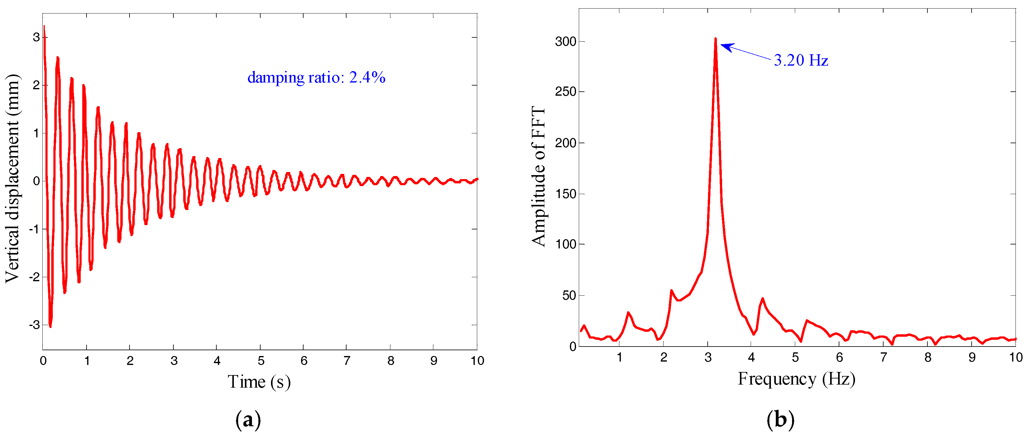
| Result | Frequency | Damping Ratio | Modal Mass |
|---|---|---|---|
| FE computation | 3.26 Hz | - | 0.728 kg |
| Experimental result | 3.20 Hz | 2.4% | - |
| Mass Ratio | ζs = 1% | ζs = 2% | ζs = 3% | |||
|---|---|---|---|---|---|---|
| μ | ropt | ζopt | ropt | ζopt | ropt | ζopt |
| μ = 0.01 | 0.9886 | 0.0625 | 0.9869 | 0.0643 | 0.9851 | 0.0662 |
| μ = 0.02 | 0.9783 | 0.0874 | 0.9761 | 0.0886 | 0.9738 | 0.0883 |
| μ = 0.03 | 0.9684 | 0.1064 | 0.9658 | 0.1084 | 0.9630 | 0.1100 |
| μ = 0.04 | 0.9588 | 0.1213 | 0.9558 | 0.1233 | 0.9526 | 0.1268 |
| μ = 0.05 | 0.9493 | 0.1355 | 0.9461 | 0.1371 | 0.9426 | 0.1413 |
| μ = 0.06 | 0.9401 | 0.1473 | 0.9367 | 0.1488 | 0.9330 | 0.1518 |
| μ = 0.07 | 0.9311 | 0.1584 | 0.9274 | 0.1604 | 0.9237 | 0.1614 |
| μ = 0.08 | 0.9222 | 0.1691 | 0.9184 | 0.1702 | 0.9145 | 0.1710 |
| μ = 0.09 | 0.9135 | 0.1784 | 0.9095 | 0.1805 | 0.9053 | 0.1817 |
| μ = 0.1 | 0.9051 | 0.1869 | 0.9010 | 0.1877 | 0.8967 | 0.1896 |
| Case | Mass Ratio | Frequency | Tuning Ratio | Damping Ratio |
|---|---|---|---|---|
| Target value | 4.4% | 3.04 Hz | 0.9508 | 12.63% |
| Experimental value | 3.07 Hz | 0.9594 | 13.9% |
© 2017 by the authors. Licensee MDPI, Basel, Switzerland. This article is an open access article distributed under the terms and conditions of the Creative Commons Attribution (CC BY) license (http://creativecommons.org/licenses/by/4.0/).
Share and Cite
Wang, W.; Dalton, D.; Hua, X.; Wang, X.; Chen, Z.; Song, G. Experimental Study on Vibration Control of a Submerged Pipeline Model by Eddy Current Tuned Mass Damper. Appl. Sci. 2017, 7, 987. https://doi.org/10.3390/app7100987
Wang W, Dalton D, Hua X, Wang X, Chen Z, Song G. Experimental Study on Vibration Control of a Submerged Pipeline Model by Eddy Current Tuned Mass Damper. Applied Sciences. 2017; 7(10):987. https://doi.org/10.3390/app7100987
Chicago/Turabian StyleWang, Wenxi, Dakota Dalton, Xugang Hua, Xiuyong Wang, Zhengqing Chen, and Gangbing Song. 2017. "Experimental Study on Vibration Control of a Submerged Pipeline Model by Eddy Current Tuned Mass Damper" Applied Sciences 7, no. 10: 987. https://doi.org/10.3390/app7100987
APA StyleWang, W., Dalton, D., Hua, X., Wang, X., Chen, Z., & Song, G. (2017). Experimental Study on Vibration Control of a Submerged Pipeline Model by Eddy Current Tuned Mass Damper. Applied Sciences, 7(10), 987. https://doi.org/10.3390/app7100987