Article

Numerical Simulation of an Oscillatory-Type Tidal Current Powered Generator Based on Robotic Fish Technology

1
Organization for Marine Science and Technology, Nagasaki University, Nagasaki 852-8521, Japan
2
Graduate School of Engineering, Nagasaki University, Nagasaki 852-8521, Japan
3
Surgical Oncology, School of Medicine, Nagasaki University, Nagasaki 852-8521, Japan
*
Author to whom correspondence should be addressed.
Appl. Sci. 2017, 7(10), 1070; https://doi.org/10.3390/app7101070
Submission received: 18 August 2017 / Revised: 12 October 2017 / Accepted: 12 October 2017 / Published: 16 October 2017
(This article belongs to the Special Issue Bio-Inspired Robotics)

Abstract

:
The generation of clean renewable energy is becoming increasingly critical, as pollution and global warming threaten the environment in which we live. While there are many different kinds of natural energy that can be harnessed, marine tidal energy offers reliability and predictability. However, harnessing energy from tidal flows is inherently difficult, due to the harsh environment. Current mechanisms used to harness tidal flows center around propeller-based solutions but are particularly prone to failure due to marine fouling from such as encrustations and seaweed entanglement and the corrosion that naturally occurs in sea water. In order to efficiently harness tidal flow energy in a cost-efficient manner, development of a mechanism that is inherently resistant to these harsh conditions is required. One such mechanism is a simple oscillatory-type mechanism based on robotic fish tail fin technology. This uses the physical phenomenon of vortex-induced oscillation, in which water currents flowing around an object induce transverse motion. We consider two specific types of oscillators, firstly a wing-type oscillator, in which the optimal elastic modulus is being sort. Secondly, the optimal selection of shape from 6 basic shapes for a reciprocating oscillating head-type oscillator. A numerical analysis tool for fluid structure-coupled problems—ANSYS—was used to select the optimum softness of material for the first type of oscillator and the best shape for the second type of oscillator, based on the exhibition of high lift coefficients. For a wing-type oscillator, an optimum elastic modulus for an air-foil was found. For a self-induced vibration-type mechanism, based on analysis of vorticity and velocity distribution, a square-shaped head exhibited a lift coefficient of more than two times that of a cylindrically shaped head. Analysis of the flow field clearly showed that the discontinuous flow caused by a square-headed oscillator results in higher lift coefficients due to intense vortex shedding, and that stable operation can be achieved by selecting the optimum length to width ratio.

Graphical Abstract

1. Introduction

In recent years, we have been faced with issues such as global warming and depletion of fossil fuels. Particularly in Japan, since the Eastern Japan earthquake disaster and the stopping of many nuclear power plants, there has been a significant effort to move towards renewable clean energy generation. As Japan is surrounded by the sea which provides stable ocean currents throughout the year, we propose an oscillatory-type tidal current-powered generator based on robotic fish technology. A sea bream robotic fish was developed in 1995, as shown in Figure 1. A flexure like a fish fin was produced from variously changing elastic modules of the flexible oscillating fin [1,2,3]. The author found that the fin had significant potential as an oscillatory-type tidal current-powered generator.
In tidal power generation, propeller-based mechanisms are predominantly used. However, maintenance costs are high, due to marine fouling from incrustations and entanglement by seaweed; the rotating propeller itself also negatively impacts the marine environment in various ways. Furthermore, the relatively high complexity of a propeller combined, with the intense corrosion that occurs in sea water, results in high manufacturing and maintenance costs. Therefore, there have been many studies on fundamentally different approaches to marine energy generation. Among them is the VIVACE system of the University of Michigan [4]. This system uses the physical phenomenon of vortex-induced oscillation, in which water currents flowing around cylinders induce transverse motion. The energy resulting from the movement of the cylinders is then converted to electricity. There is also a small reciprocating-type generator in Japan, made by Abiru at Fukuoka Industrial University [5], in which the fluttering behavior of a wing is used. Further, a water flow-powered generator using pendulum-oscillation has been developed at Okayama University [6,7], which uses the same principle as the VIVACE system.
The authors’ aim is to provide some assistance toward developing a more efficient reciprocating-type power generating system. Specifically, with regard to determining the optimal elastic modulus of a wing foil-type oscillator, and the optimum shape of a reciprocating oscillator head (from a group of six common shapes) to provide high lift coefficients when these oscillating heads are placed in transverse flows. The focus of this paper is on the optimization of this lift force. The magnitude of the “coefficient of lift” ( C l ) varies with the shape of the oscillating mechanism. Therefore, as the oscillator is the main part of a reciprocating type generator, it’s design is critical. The purpose of this study is to find the shape of oscillator head that produces the largest C l .
To begin with, the optimum shape of the oscillator is found through numerical analysis; then, a physical machine using the oscillator will be created for further testing. A problem with coupling fluid flow to an object/mechanism must be solved, because the flow pressure causes deformation and displacement of the object (in this case, the oscillator), and the movement of the object in turn affects the flow (its velocity, pressure, etc.). The interdependent fluid-mechanical coupled system is numerically simulated in ANSYS.
The fundamental equations of the two-way coupled problem are as follows:
The unsteady flow field (incompressible) around the oscillator is governed by the following Navier-Stokes equation, and the equation of continuity, where t is the time, ρ is the mass of the flow, V is the velocity, F is the body force and p is the pressure:
ρ d V d t   =   F p + μ 2 V ,   · V   =   0
And the equation governing the solid is derived from Newton’s second law:
a s   =   m s · σ s + g s
Here m s is the mass of the solid, a s is the acceleration, σ s is the stress tensor on the solid and g s is the body force.
The coupling equations are (displacement d, fluid subscript f, and solid s):
τ f n f   =   τ s n s                 d f   =   d s
where τ is the stress and n the normal vector. The lift force L is defined as
L ( t )   =   C l 1 2 v 2 ρ A
where ρ is the density of the flow and A is the projected area of the body in the direction perpendicular to the flow. It is clear from the equation that, in a determined flow with a determined velocity, the magnitude of lift force is determined by C l and A . That is, a shape with a large C l , as well as an appropriately large A , is required. Furthermore, a lift that consistently varies is desirable, in order to facilitate reciprocation.
Regarding the calculation parameters, a flow velocity of Vx = 0.5 m/s [8] is used, because this is the slowest tidal speed that can be used for generating power. The Reynold’s number is approximately 7.5 × 10⁴, because the oscillator size against the flow is 0.15 m. A uniform flow field with Vx = 0.5 m/s (flow from the left side—x direction) is used in all of the following calculations [9].

2. Study on an Airfoil-Type Oscillator

An airfoil shape would naturally be thought of as a logical shape for generating a large C l . However, it does not oscillate unless it is exposed to an appropriate turbulent flow. Furthermore, based on the authors’ efforts to mechanically emulate the propulsion mechanism that can be observed in a regularly shaped fish as it swims at very high speeds, it was considered to be a natural selection for the oscillator [10,11]. On the assumption that C l would increase if there were some elasticity in the oscillating wing, a numerical experiment to find the optimum elastic modulus on a symmetric foil was carried out.
As shown in Figure 2, an NACA0015 model foil, with a shaft located at 0.1 m from the front leading edge is used (the shaft is not considered in the calculation). A reciprocating displacement of y = 0.001 sin(2πt) m is given to the shaft, and the elastic modulus E of the foil is varied stepwise from E = 108 to 5 × 10⁴ Pa to investigate the change of C l , details of the simulation conditions are provided in Table 1.
This two way FSI problem was solved using ANSYS Mechanical and ANSYS FLUENT (14.5, Ansys inc., Canonsburg, PA, USA) [12] controlled by System Coupling. The results are plotted in Figure 3, from which significant variation of C l due to variation in E can be clearly seen. When the foil’s E = 108 Pa, there is almost no deformation; however, when E = 106 Pa, the maximum C l is obtained, where C l is approximately three times greater. However, the C l will also drop when the value of E is decreased. Therefore, it can be concluded that the optimum elastic modulus is E = 106 Pa for this shape of foil, in the case of different cambers the optimum value of E will most likely vary.
The overall deformation of the foil for E = 5 × 10⁴, 106 Pa, and 108 Pa has been examined, providing an optimal C l value for E = 106 Pa. The scale in the y direction is scaled up as the deformation is very small. E = 108 is not shown here, as the deformation is insignificant. Instantaneous deformations of the foil for E = 5 × 10⁴ and E = 106 are shown in Figure 4 and Figure 5, respectively. It is recognized that, compared to the case of E = 5 × 10⁴, in which the body curves with more than one center of curvature, in the case of E = 106, the foil is singularly concave or convex, providing an asymmetric foil. This forms an attack angle for the foil, and is the reason for the increase of C l .
Clearly, the lift force of a foil will change according to its attack angle. The lift increases as the attack angle increases within the range of ±15°. Facilitation of this lift angle must be considered when manufacturing an elastic oscillator-based power generator; however, this study only investigated the influence of the rigidity. In conclusion, this study has shown that the optimum value of the elastic modulus is E = 106 Pa; the lift will decrease with any increase or reduction of the value of E.
A reciprocating displacement of y = 0.002 sin(2πt) m occurs when E = 106 Pa. The C l is three times that of the previous y = 0.001 sin(2πt) m. However, the calculation failed due to the occurrence of negative meshes when a larger displacement was used. The authors will investigate the reason for this in future research.

3. The Optimum Shape of a Reciprocating Oscillator for Self-Induced Oscillation

3.1. The Pre-Test in 2D
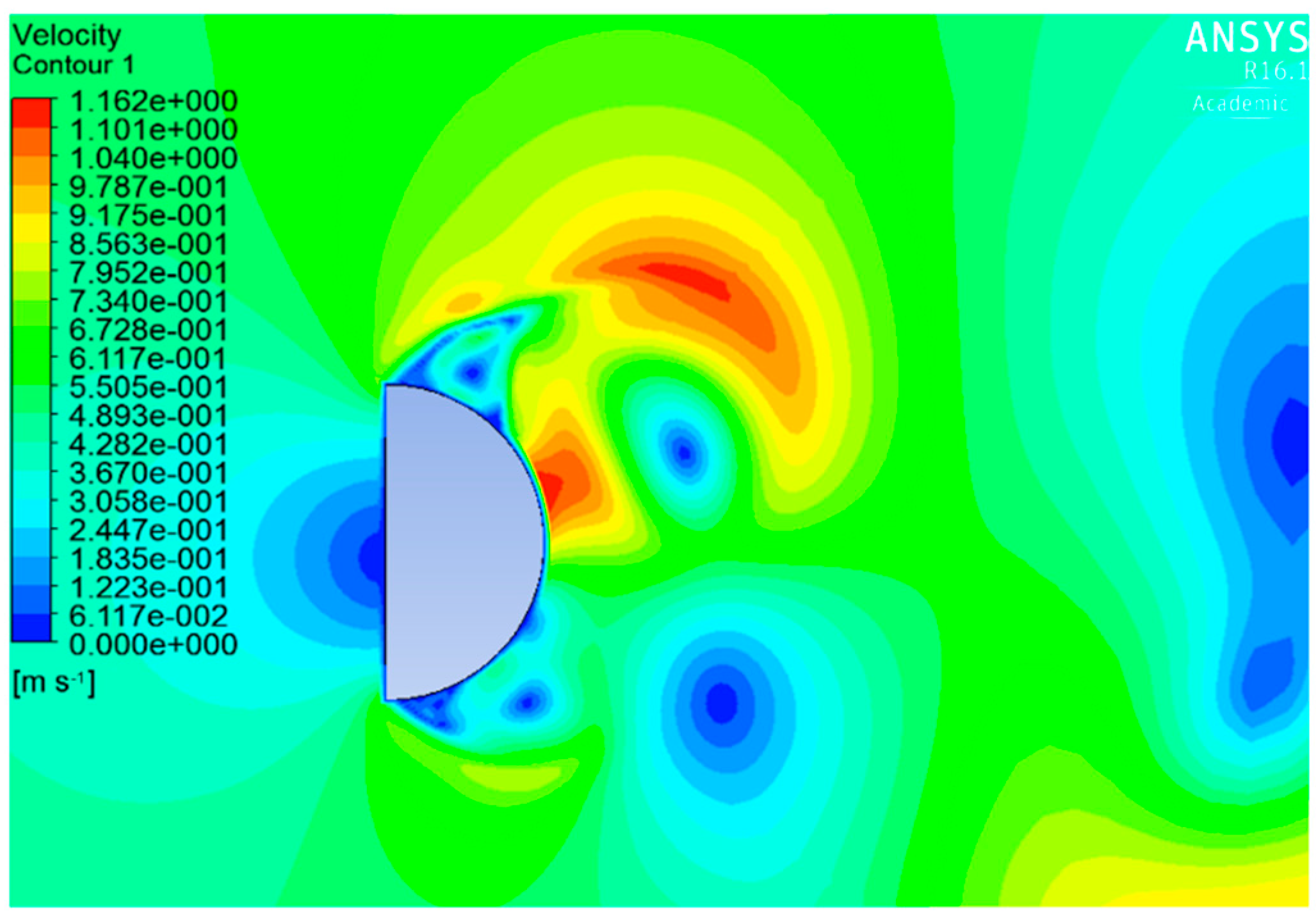
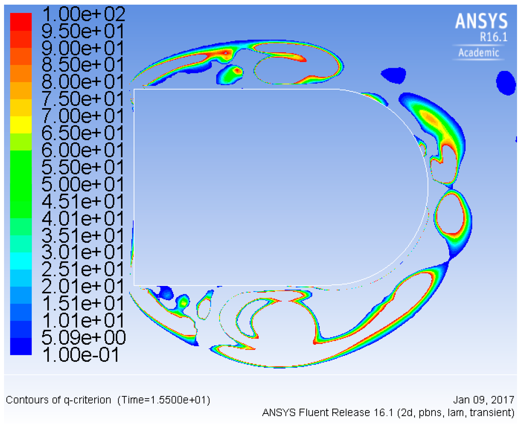
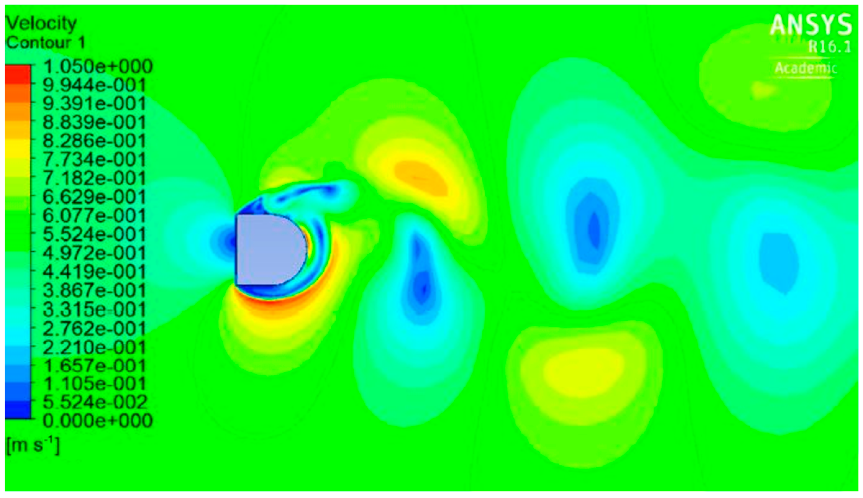
An essential requirement for a self-induced oscillator like VIVACE’s is the stable shedding of vortices. For this reason, the authors attempted to find a shape that could stably shed vortices more effectively than that of a circular shaped interface, as well as providing an increase in C l [13]. According to experiments by Hiejima in Okayama University, the oscillation of a semicircular-shaped oscillator is better than that of a circle when the plane face of the semicircle is against the flow. Also, according to Equation (4), the dimension parallel to the flow is proportional to the lift force. Based on the above two facts, the authors experimented with an elongated semicircle (rectangle plus semicircle). As the pre-test, models of various shapes, including those in Table 2, were made for two-dimensional calculations to investigate their C l values. The mesh resolution around the model was set to 240 in order to see the vortex clearly. ICEM CFD (16.1, Ansys inc., Canonsburg, PA, USA) was used for meshing and FLUENT was used for calculating the flow. A 2D flow domain with a size of 4 × 3 (m) (x × y) was used, and the time step size was 0.05 s. The convergence of the calculation was acceptable, as the maximum residuals of iterations were under 0.01.
Table 2 shows part of the results. It is clear that the semicircle has a higher C l value than the circular shape. The elongated semicircle also has a higher C l value; however, the oscillation is not stable, making it impractical for power generation. The reason for this phenomenon of instability in the case of the elongated semicircle was investigated by checking the flow field and vorticity for each case. The reason for this instability was the discontinuous flow resulting from a higher flow rate, and the ensuing reattachment of the separated flow.

3.1.1. Reason for a Higher C l Value in the Case of a Semicircle

From Figure 6, it can be seen that, in the case of a circle, the flow velocity changes from zero to its maximum gradually, from the forefront to a separation point, this is also reflected in the vorticity (Figure 7) and there is only a slight variation in angle between the stream in the x direction. In contrast, in the case of the semicircle, as shown in Figure 8 rapid streams occur at the edges and separate at an angle of about 45 degrees to the x direction, as the watercourse suddenly narrows. The maximum velocity of this case is 1.44 times that of the circle, and the negative pressure becomes about three times greater.
However, it was noted that a trace of the oscillation of C l showed slight irregularity, indicating some instability, as shown in Figure 9 The reason for this can be seen in the distribution of velocity and vorticity. Figure 8 and Figure 10 show t = 18 s when a vortex is shedding and the lift is downward. The back of the rapid stream produces a dead water region which extends in the x direction up to half the width of the object (see Figure 8). The flow will then reattach to the object and reconnect to the rapid flow (this phenomenon can be observed in both Figure 8 and Figure 11). In the case of the semicircle, reattachment occurs to the rear on the circular side (see Figure 8), the gradually increasing region of rapid velocity due to reattachment, together with the rapid stream from the edge, forms a strong vortex, which is then shed (see Figure 10), providing the object with a strong lifting force. As a result, the object will oscillate as the vortex makes contact with it.

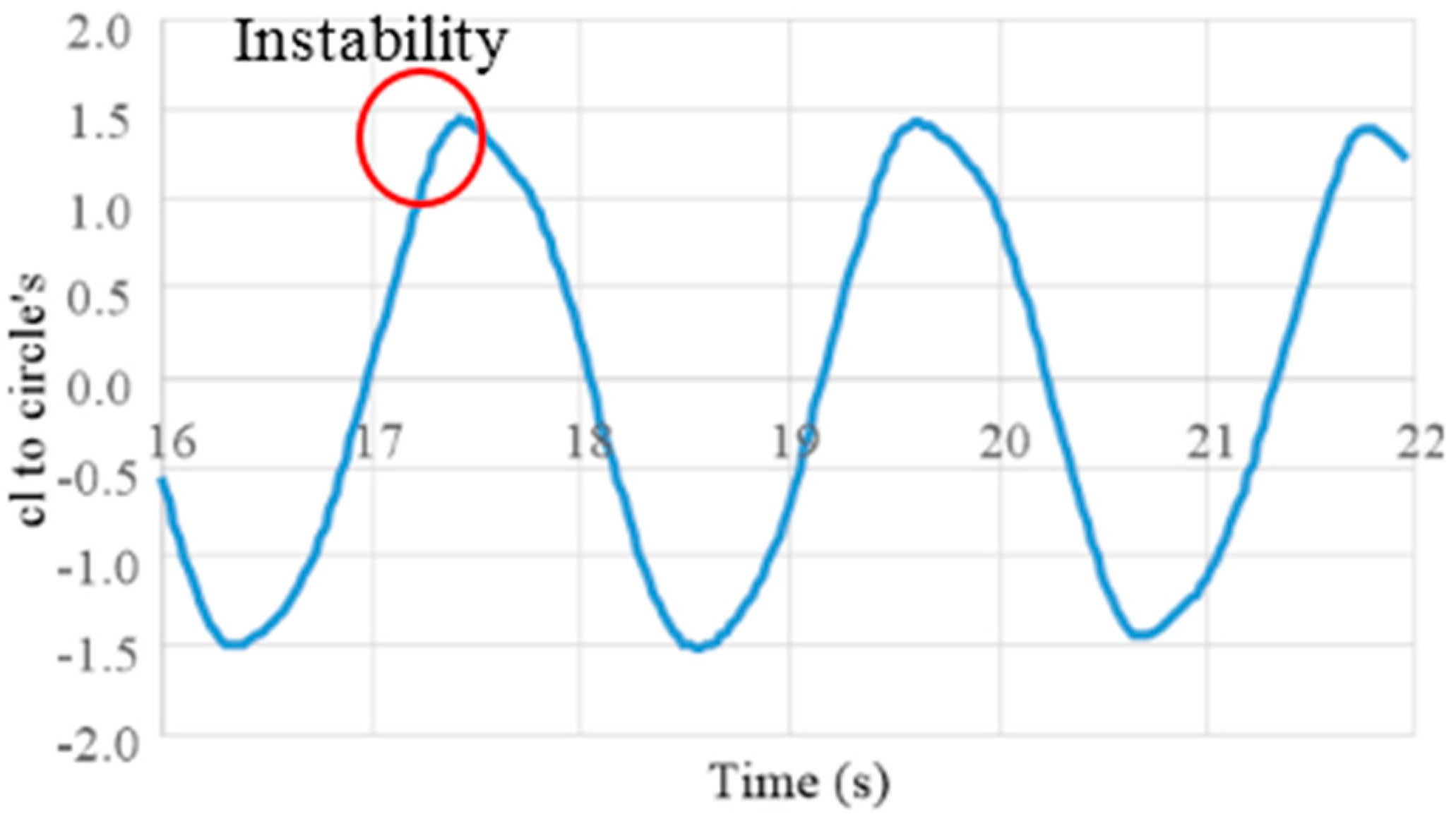
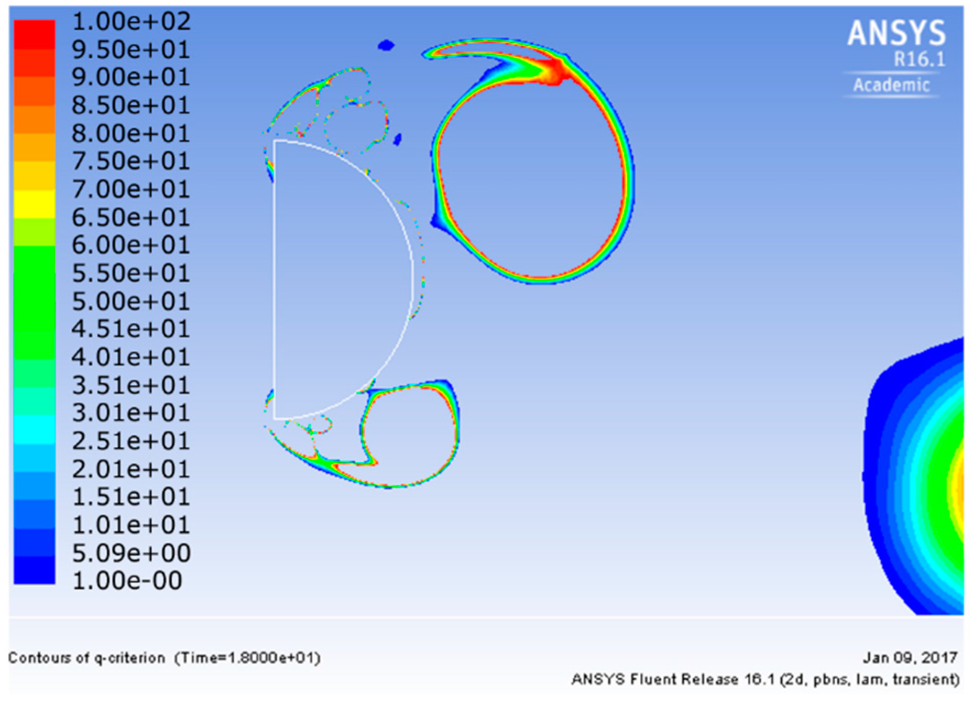
3.1.2. Reason for Increasing Instability with Elongation

The lift force is mainly produced by the vortex shedding on the opposite side of the rapid stream separating from the edge, in the case of an extended semicircle. The main difference is that the region of reattachment occurs in a plane parallel to the object’s body, as shown in Figure 11; this rapid flow region will move to the rear with time, producing a moving negative-pressure zone. This kind of reattachment causes unstable oscillation, since its distribution of vorticity is irregular, as shown in Figure 12.
On the other hand, an elliptically headed shape with its major axis parallel to the x direction produced a regular sinusoidal oscillation as is reflected in the stability data in Table 2, even when extended in the x direction. Its drag force reduces, and the maximum velocity of flow is 0.9 times that of a circle. Therefore, the period for vortex shedding is a little longer, and the intensity of the vortex also reduces compared to the circle. Elongation in the x direction increases C l ; however, the oscillation becomes increasingly unstable. This occurs because the shed vortex reattaches to the object. This analysis confirmed that a regular oscillation of C l can be obtained if the ratio of length to width is under two.

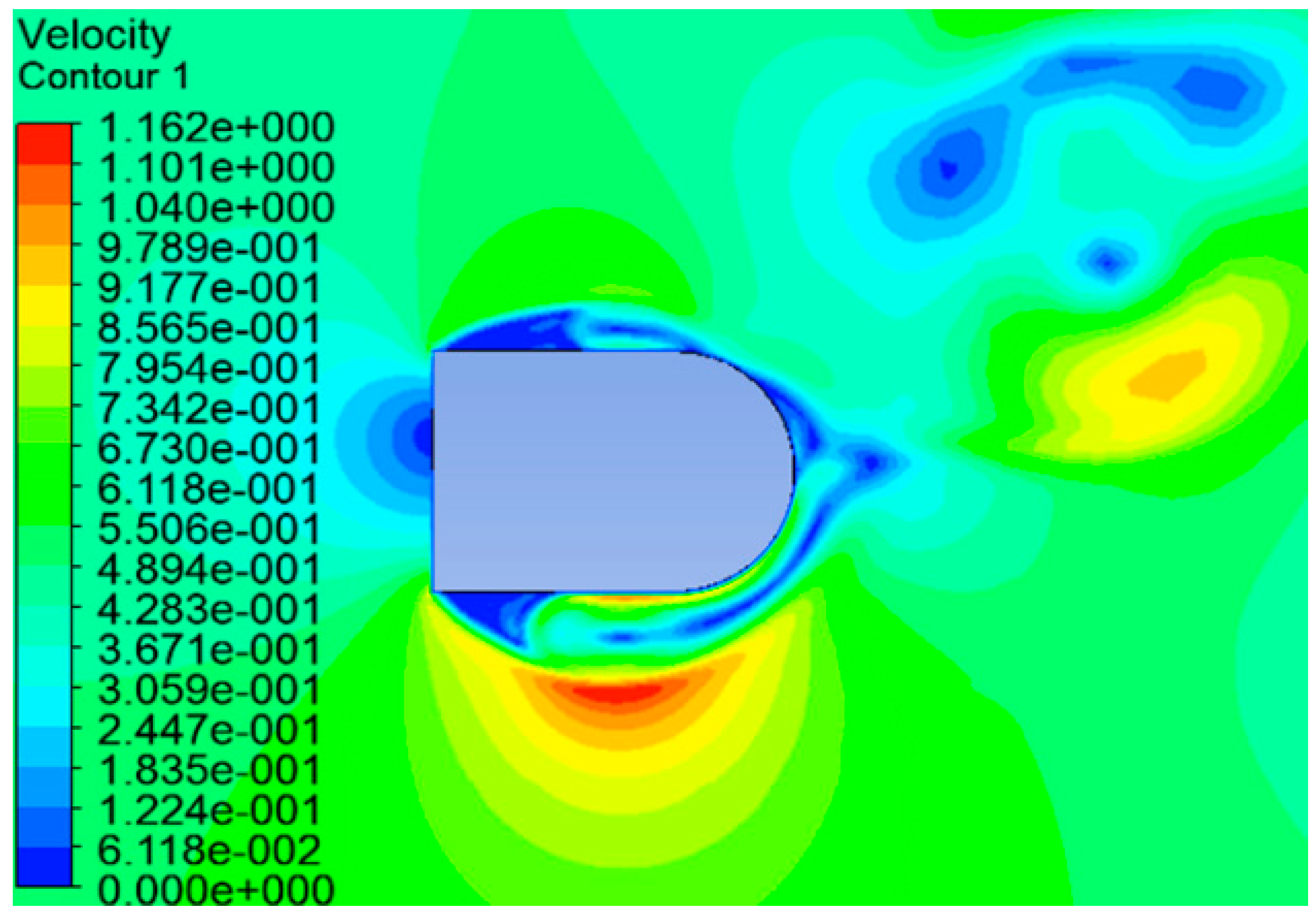
3.1.3. Finding a Model with Optimal Length in the x-Direction

Comparing models 2 and 3, model 2 is more stable. The distribution of model 2’s velocity is shown in Figure 13; this is similar to that of model 1, shown in Figure 6. It is therefore also expected to provide stable oscillation.
From the results in Table 2, it is clear that the square-headed shapes produce greater C l , except in cases where oscillation becomes unstable. However, the reattachment of a shed vortex must be avoided. Based on the above 2D analysis results, a 3D simulation of the fluid-structure coupling of a square-headed shaped oscillator was carried out.

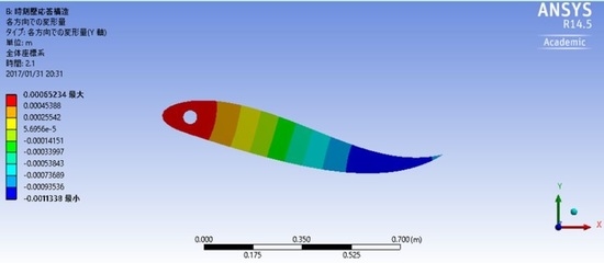
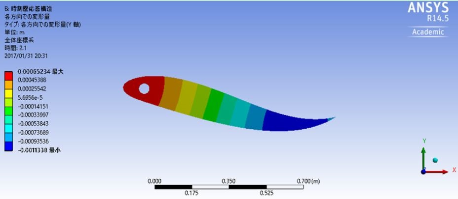
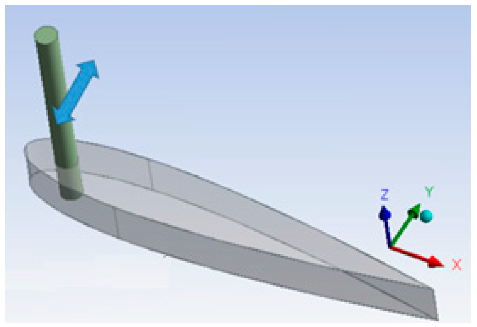
3.1.4. 3D Fluid-Structure Coupled Analysis

The simulation conditions for the coupled problem are listed in Table 3. Based on the previously discussed results, the authors consider that model 2 (ref. to Table 2) may be optimal, as it produces higher C l and is relatively stable. Model 1, a semicircle, was analyzed for comparison. Model 3 was an elongated version of model 2. In order to compare their maximum C l , the weight of the three models with varying lengths in the x direction are the same, as is the support constraint. (Elastic base setting to move 0.01 m under a force of 1.92 N). The mechanics are shown in Figure 14, in which the reciprocating motion in the y direction from the oscillator parallel to z direction will be transmitted to a shaft, then the motion will be converted into rotation by an appropriate mechanism in order to generate electricity. Care was required in order to avoid negative meshes, the mesh type and its size, together with the total number of meshes, including the scale of the fluid domain, were iterated, as dynamic mesh is required for three-dimensional simulation; furthermore, an academic version of ANSYS was used, which involves some limitations. The convergence of the calculation was acceptable. However, the residues were a little higher than for the 2D case, indicating the presence of some error. The computing precision is currently limited by the use of a regular PC for simulation; in the future, this will be addressed by an upgrade of the processing environment.
The simulation results are shown in Table 4. From the results, it can be concluded that C l increases with elongation in the x direction, as was observed in the 2D model. However, the maximum displacement of model 3 is less than that of model 2. Based on the previously observed data, this reduction of output will be due to instability, resulting in an inability to meet the conditions required to move the object (oscillate). It can be concluded that model 2 is the optimum shape from among those investigated in this study.
Model 6 in Table 2 may also be optimal based on its stability and high C l . However, the coupled simulation result cannot be compared with those in Table 4, as the simulation failed under these specific conditions; the simulation, however, was successful with different weight and support parameters. Clearly the relationships between C l , model weight, supporting conditions, and optimum length require further research.
The square-headed model has a higher C l compared to the circular model. However, a very important aspect regarding installation of this mechanism is that, if it is not perpendicularly installed to the flow, reciprocation will not occur.

4. Conclusions

(1)
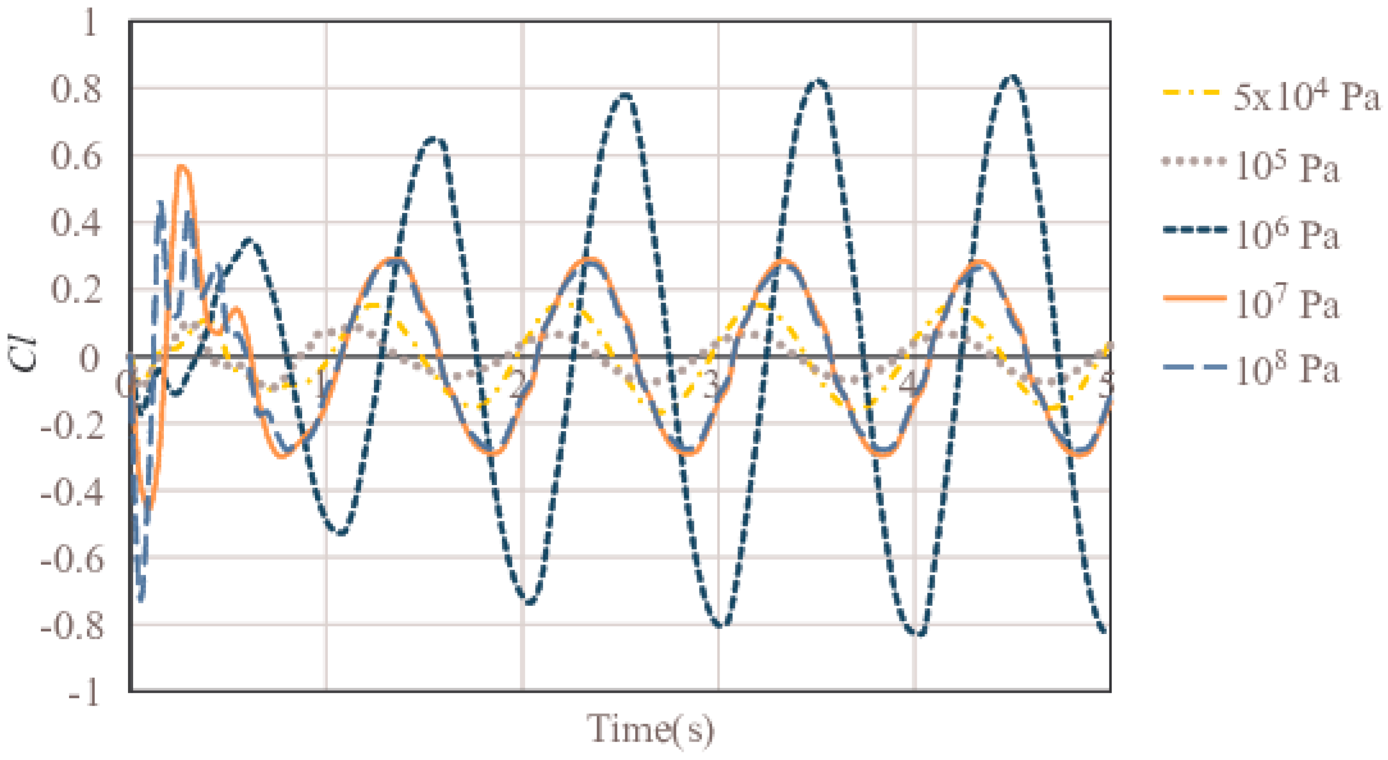
An airfoil-shaped oscillator with optimal elasticity effectively increases lift, and we found that the elastic modulus E = 106 Pa is the best for a NACA0015 model foil.
(2)
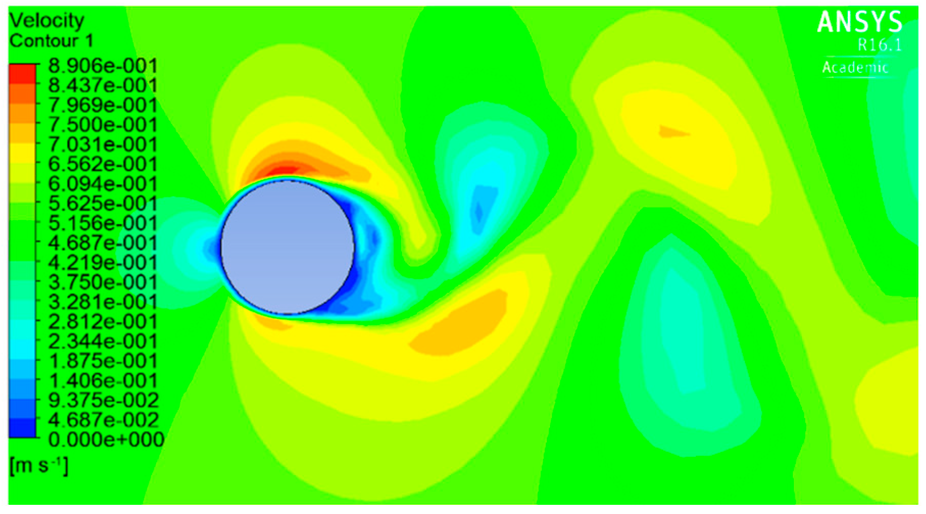
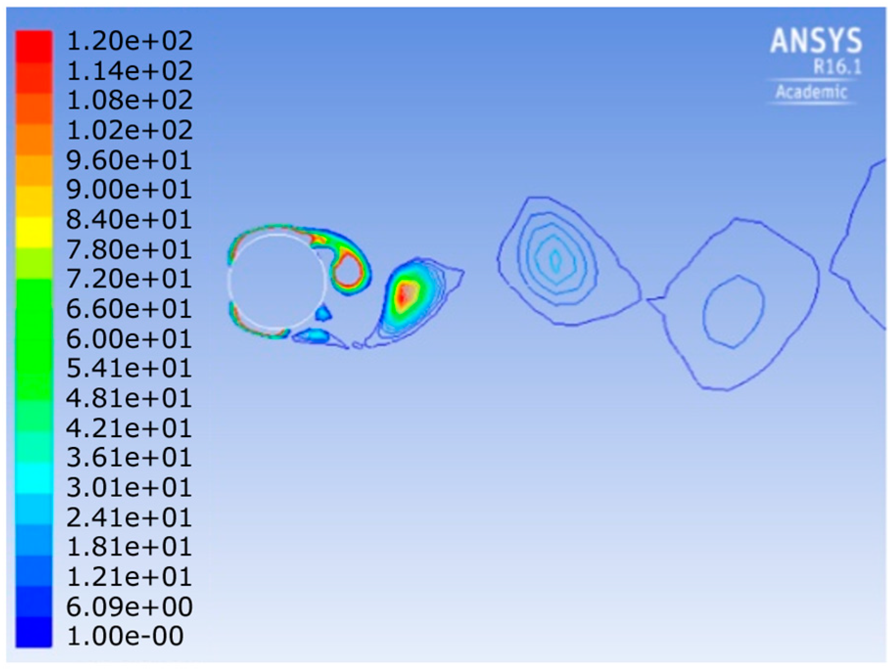
Analysis of the flow field for six common head shapes clearly showed that the discontinuous flow caused by a square-headed oscillator results in higher Cl due to intense vortex shedding. Stable operation can be achieved by selecting the optimum length to width ratio, and this ratio is confirmed to be one (square) by our simulation.
(3)
A shape with a higher Cl than the semicircle has been identified, and the efficacy of this shape was confirmed in the fluid-structure coupled analysis.
As was mentioned in the introduction, this study is limited to the numerical simulation of two oscillator based generators. Clearly, more extensive simulations are needed on which to base potential relationships between the parameters involved. Such optimization will require iterative design, simulation, prototyping and testing of physical models before a comparison with existing technologies can be objectively made.

Acknowledgments

The authors express their sincere gratitude to Wei Deng, Jincheng Xu, Qiangqiang Ren, and Joshua Lawn for supporting the research.

Author Contributions

I.Y. supervised this research, G.R. planned this paper, G.R. and Y.S. carried out the simulations, I.Y., G.R., Y.S. and M.L. together wrote up the paper. The English was checked by M.L.

Conflicts of Interest

The authors declare no conflict of interest.

References

  1. Yamamoto, I. Practical Robotics and Mechatronics: Marine, Space and Medical Applications; IET: Croydon, UK, 2016; pp. 1–192. [Google Scholar]
  2. Yamamoto, I. Propulsion system with flexible/rigid oscillating fin. IEEE J. Ocean. Eng. 1995, 20, 23–30. [Google Scholar] [CrossRef]
  3. Yamamoto, I.; Terada, Y.; Nagamatu, T.; Imaizumi, Y. Research on an oscillating fin propulsion control system. In Proceedings of the OCEANS ‘93: Engineering in Harmony with Ocean, Victoria, BC, Canada, 18–21 October 1993. [Google Scholar] [CrossRef]
  4. University of Michigan. Available online: http://www.vortexhydroenergy.com/ (accessed on 30 November 2016).
  5. Abiru, H.; Yoshitake, A. Experimental Study on a Cascade Flapping Wing Hydroelectric Power Generator. J. Energy Power Eng. 2012, 6, 1429–1436. [Google Scholar]
  6. Hiejima, S.; Nakano, S. Experimental study on control parameters for aerodynamic vibration-based power generation using feedback amplification. J. Jpn. Soc. Civ. Eng. 2012, 68, 88–97. [Google Scholar] [CrossRef]
  7. Hiejima, S.; Hiyoshi, Y. Vibrational amplification technique for power generation using wind-induced vibration. Wind Energy 2010, 34, 135–141. [Google Scholar]
  8. Annual Report on the Environment in Japan 2016. Available online: http://www.env.go.jp/en/wpaper/2016/pdf/2016_all.pdf (accessed on 14 October 2017).
  9. Rodríguez, I.; Lehmkuhl, O.; Chiva, J.; Borrell, R.; Oliva, A. On the flow past a circular cylinder from critical to super-critical Reynolds numbers: Wake topology and vortex shedding. Int. J. Heat Fluid Flow 2015, 55, 91–103. [Google Scholar] [CrossRef] [Green Version]
  10. Hu, W. Hydrodynamic study on a pectoral fin rowing model of a fish. J. Hydrodyn. 2009, 21, 463–472. [Google Scholar] [CrossRef]
  11. Xu, Y.; Wan, D. Numerical simulations of fish swimming with rigid pectoral fins. J. Hydrodyn. 2012, 24, 263–272. [Google Scholar] [CrossRef]
  12. ANSYS (Flunet, Mechanical) User’s Manual in Japanese. Available online: http://tsubame.gsic.titech.ac.jp/docs/guides/isv-apps/fluent/pdf/Fluent.pdf (accessed on 14 October 2017).
  13. Sun, X.; Kato, N.; Li, H. Effects of cross section and flexibility of pectoral fins on the swimming performance of biomimetic underwater vehicles. J. Jpn. Soc. Nav. Archit. Ocean Eng. 2012, 15, 175–189. [Google Scholar] [CrossRef]
Figure 1. Sea bream robotic fish.
Applsci 07 01070 g001
Figure 2. NACA0015 foil simulation model.
Applsci 07 01070 g002
Figure 3. Variation of coefficient of lift (Cl) versus rigidity.
Applsci 07 01070 g003
Figure 4. Deformation in case of E = 5 × 10⁴ Pa at t = 2.1 s, C l is reduced at this instant. Scale in y direction is scaled up.
Applsci 07 01070 g004
Figure 5. Deformation in case of E = 106 Pa at t = 2.1 s, C l will increase after this instant. Scale in y direction is scaled up.
Applsci 07 01070 g005
Figure 6. Distribution of velocity for a circle at t = 15.4 s. Descending C l .
Applsci 07 01070 g006
Figure 7. Distribution of vorticity for a circle at t = 15.4 s. Descending C l .
Applsci 07 01070 g007
Figure 8. Distribution of velocity for a semicircle at t = 18 s. Descending C l .
Applsci 07 01070 g008
Figure 9. Sinusoidal trace of C l for a semicircle.
Applsci 07 01070 g009
Figure 10. Distribution of vorticity for a semicircle at t = 18 s. Descending C l .
Applsci 07 01070 g010
Figure 11. Distribution of velocity for an extended semicircle (model 3) at t = 15.5 s. Oscillation is unstable.
Applsci 07 01070 g011
Figure 12. Distribution of vorticity for an extended semicircle (model 3) at t = 15.5 s. Oscillation is unstable.
Applsci 07 01070 g012
Figure 13. Distribution of velocity for an extended semicircle (model 2) at t = 23.75 s. The reattached region is moving to the rear on the circular side of the object.
Applsci 07 01070 g013
Figure 14. Model for coupling calculation.
Applsci 07 01070 g014
Table 1. Simulation conditions.
Time Step Size for Flow Calc. (s)0.005
Scale of flow domain (m)6 × 3 × 0.1
Type of meshprism
Min. size of mesh (m)0.007
Density of structure (kg/m3)1000
Length of structure (m)1
Depth of structure (m)0.1
Table 2. Results of the pre-test.
Shapex/yMax C l to Circle’sPeriodicStabilityCd * to Circle
1 Applsci 07 01070 i0010.51.53goodnot good1.67
2 Applsci 07 01070 i00211.92goodnot good1.67
3 Applsci 07 01070 i0031.43.2detectedVery poor1.67
4 Applsci 07 01070 i0042.51.3excellentexcellent0.5
5 Applsci 07 01070 i00511.53excellentgood1.67
6 Applsci 07 01070 i00611.97excellentexcellent1.67
* Cd coefficient of drag.
Table 3. Conditions for the fluid-structure coupled problem.
Flow time step size (s)0.005
Flow domain scale (m)3 × 2 × 0.1
Flow domain mesh typeprism
Min. size of mesh (m)0.017
Weight of struc. model (kg)1.62
Size of model 1 (m)0.075 × 0.15 × 0.1
Size of model 2 (m)0.15 × 0.15 × 0.1
Size of model 3 (m)0.18 × 0.15 × 0.1
Dia. of hole in models (m)0.04
Elastic base (N/m3)48,000
Table 4. Results from coupling calculation.
ModelSize in x-direc. (m)Max C l Max Disp. (m)
No.10.07570.0120
No.20.158.80.0213
No.30.18100.0198

