Abstract
With the development of intelligent machine tools, monitoring the vibration by the accelerometer is an important issue. Accelerometers used for measuring vibration signals during milling processes require the characteristics of high sensitivity, high resolution, and high bandwidth. A commonly used accelerometer is the lead zirconate titanate (PZT) type; however, integrating it into intelligent modules is excessively expensive and difficult. Therefore, the micro electro mechanical systems (MEMS) accelerometer is an alternative with the advantages of lower price and superior integration. In the present study, we integrated two MEMS accelerometer chips into a low-pass filter and housing to develop a low-cost dual-axis accelerometer with a bandwidth of 5 kHz and a full scale range of ±50 g for measuring machine tool vibration. In addition, a platform for measuring the linearity, cross-axis sensitivity and frequency response of the MEMS accelerometer by using the back-to-back calibration method was also developed. Finally, cutting experiments with steady and chatter cutting were performed to verify the results of comparing the MEMS accelerometer with the PZT accelerometer in the time and frequency domains. The results demonstrated that the dual-axis MEMS accelerometer is suitable for monitoring the vibration of machine tools at low cost.
1. Introduction
With the trend of industry 4.0 and intelligent production, many experts have devoted efforts to incorporate intelligent technology into machine tools [1,2,3,4,5,6,7,8]. The core technology of intelligent machine tools can detect temperature, vibration, and displacement, and can be controlled and compensated through algorithms for enhancing the processing performance [9,10]. Therefore, numerous additional sensors are necessary to provide real-time measurement while minimally increasing costs [11,12,13,14]. In particular, lead zirconate titanate (PZT)-type accelerometers are regularly used to monitor the vibration and chatter during cutting processes, thereby satisfying the specifications of a 5 kHz bandwidth and a full-scale range of ±40 g. However, such accelerometers are too expensive ($500–$1000) to integrate into intelligent modules. By contrast, micro electro mechanical systems (MEMS)-type accelerometers are less expensive but typically exhibit the disadvantages of high noise and a low bandwidth [15].
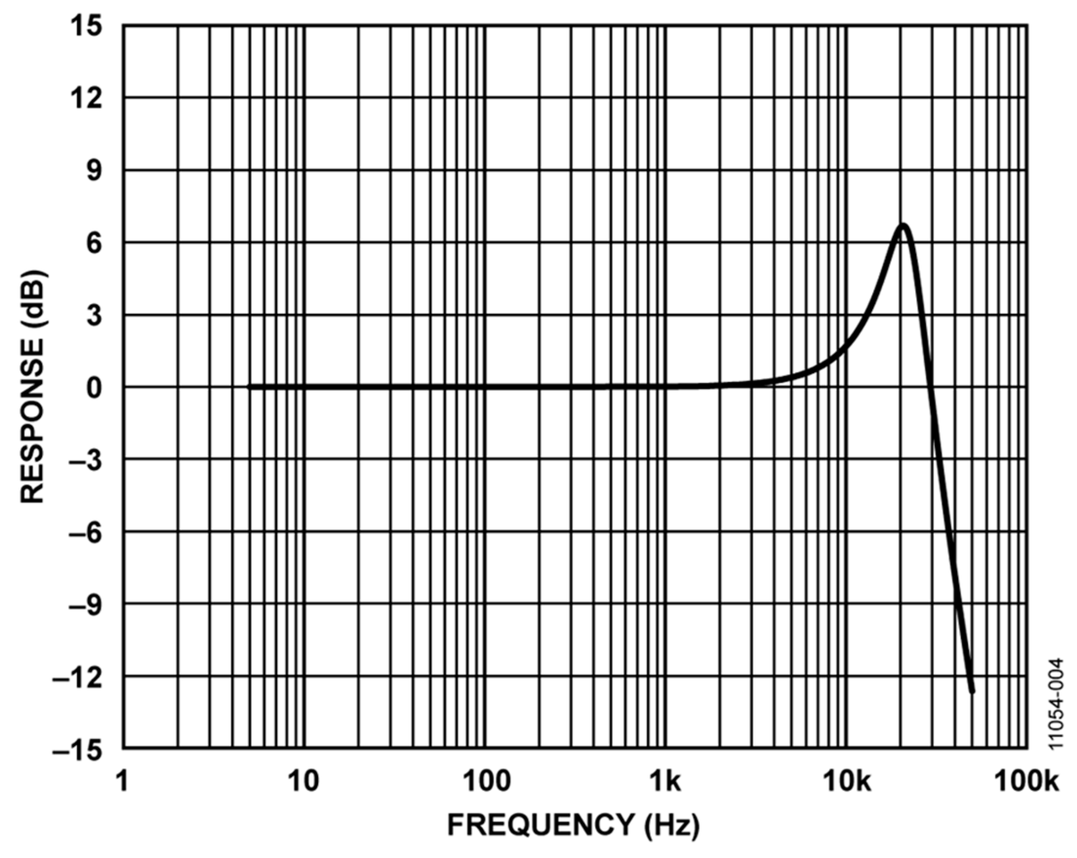
With the upgrading of MEMS technology, the aforementioned disadvantages can be improved through advanced design and process methods. In this study, a differential capacitance ADXL001 MEMS accelerometer (Analog Devices, Inc., Norwood, MA, USA) was used. This accelerometer has a bandwidth of 22 kHz, a full-scale range of ±70 g, and a sensitivity of 24.2 mV/g, thereby providing a fully differential sensor structure and circuit path for excellent resistance to electromagnetic interference (EMI) and radio frequency interference (RFI). The performance and frequency response are shown in Figure 1 [16]. Measuring the vibration of machine tools generally requires dual-axis accelerometers, sufficient rigidity housing, and close adhesion with the machine. Otherwise, the accuracy and effective frequency range of measurement can be compromised. Because an ADXL001 accelerometer is a chip form of a uniaxial accelerometer, we combined two accelerometers and designed a filter circuit with housing and a fixed magnetic structure to satisfy the measurement requirements. In addition, we also developed a platform for evaluating the sensitivity of the MEMS accelerometer based on the ISO-16063-21 back-to-back calibration method [17,18]. After testing the sensitivity of the MEMS accelerometer, we designed the package of the MEMS accelerometer and analyzed the heat and resonance frequency. Finally, a milling experiment was performed to verify the results of comparing the MEMS accelerometer with the PZT accelerometer in the time and frequency domains.

Figure 1.
The frequency response of the ADXL001 sensor [16].
2. Development of Dual-Axis Micro Electro Mechanical Systems (MEMS) Accelerometers
2.1. Low-Pass Filter Circuit
Vibration signals greater than 5 kHz are regarded as noise during the cutting processes of machine tools. Because the bandwidth of the ADXL001 accelerometer is 22 kHz, we designed a passive first-order low-pass resistor–capacitor (RC) filter to obtain an effective measurement signal. The values of R and C are evaluated using Equation (1):
where f0: cut-off frequency = 5 kHz; in this case, C = 20 nF, R = 1.6 kΩ. The design of the circuit layout and the related components were mounted on a printed circuit board (PCB) (15 mm × 15 mm), as shown in Figure 2.
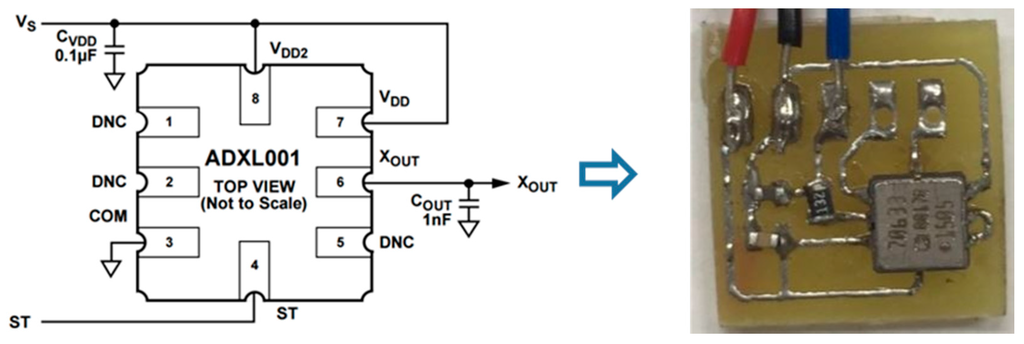
Figure 2.
The circuit layout of the low-pass filter. DNC: Do Not Connect; ST: Self Test.
2.2. Housing and Fixed Magnetic Structure
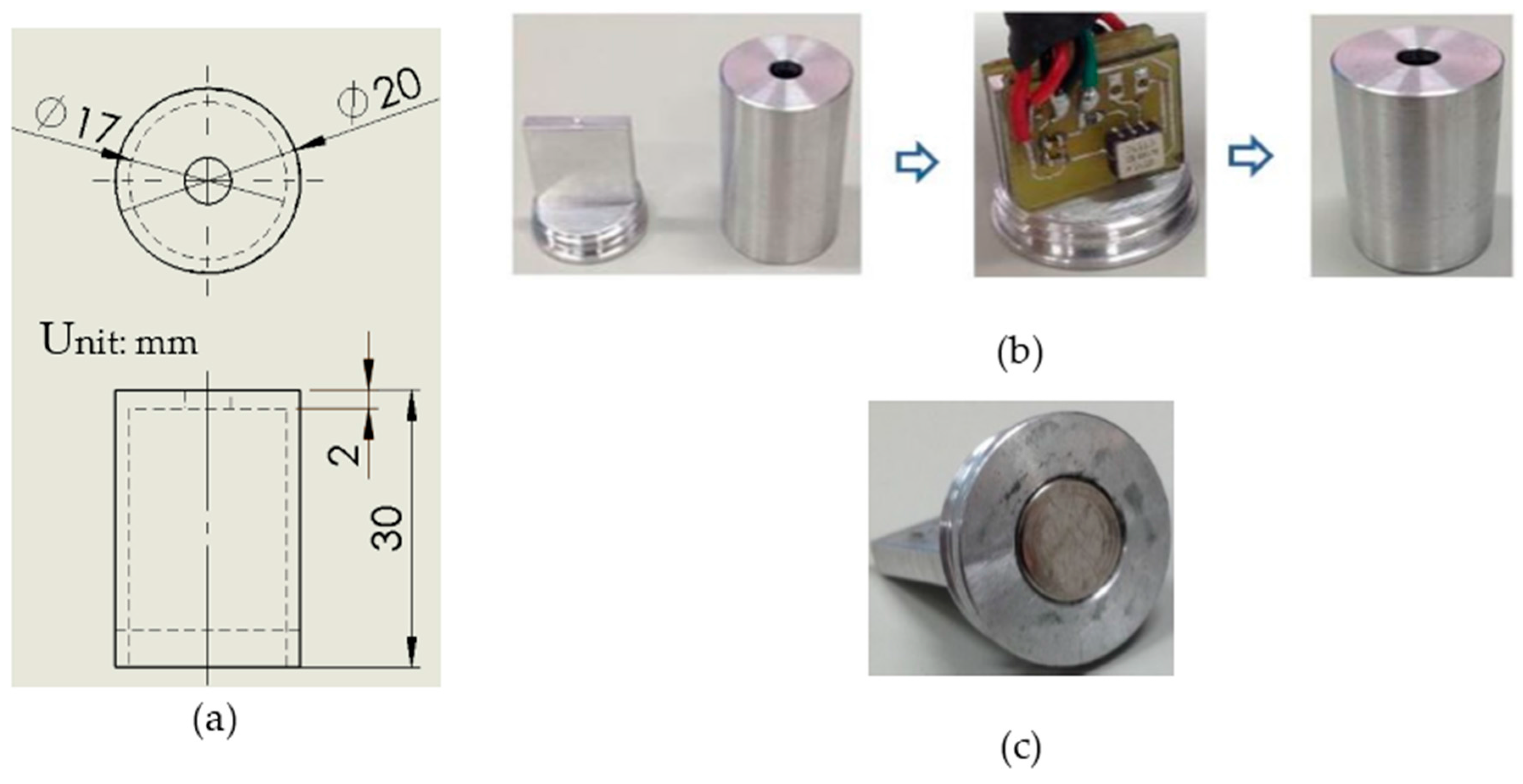
The housing design should be small, lightweight, and structurally rigid. Moreover, the sensitive axis of the ADXL001 accelerometer is perpendicular to the surface of the spindle. Therefore, we utilized AL7075 materials to design housing that was internally rectangular but externally cylindrical (φ20 mm × H30 mm). The geometric design and dimension of the accelerometer housing are shown in Figure 3a. In the process of assembly, the ADXL001 was attached on each side of the rectangular structure, which is sensitive to vibration on both the x- and y-axes, as shown in Figure 3b.

Figure 3.
(a) The geometric design and dimension of the accelerometer housing; (b) The assembly of the housing and micro electro mechanical systems (MEMS) accelerometer; (c) The structure of fixed magnetic base.
The fixed condition between the accelerometer and the machine affects the effective frequency range of measurement. For close adhesion with the machine, we utilized a magnetic structure on the bottom of the housing, as shown in Figure 3c.
2.3. The Modal Analysis of Housing
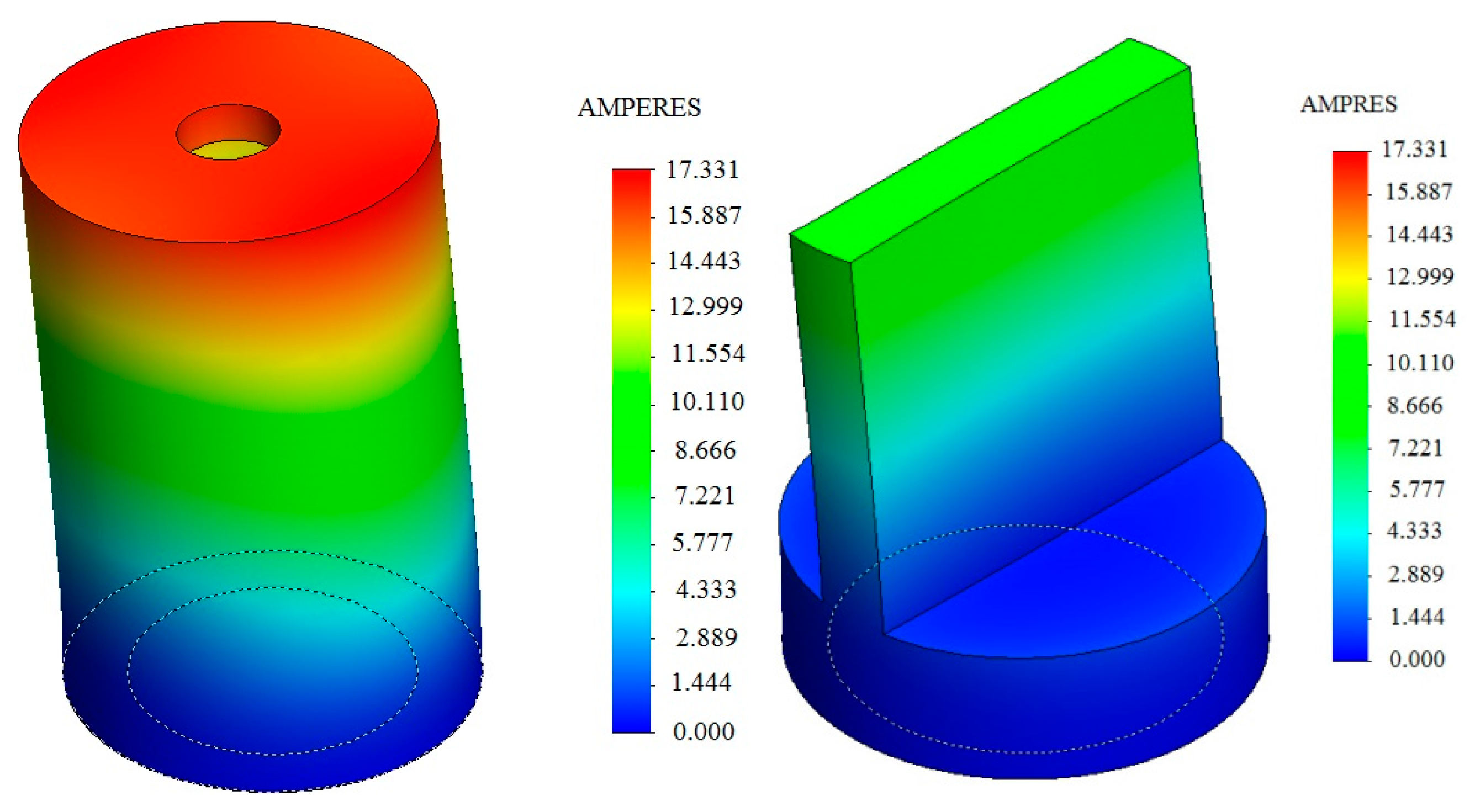
The bottom of the housing is set and fixed to disregard the external load. The SolidWorks simulation software (SolidWorks Inc., SolidWorks 2014 SP0, Waltham, MA, USA, 2014) was utilized to perform the finite element method (FEM) analysis and determine the natural mode shapes and frequencies. The results of model analysis revealed the minimum natural frequency was approximately 12.31 kHz, which had a mode shape as shown in Figure 4. An effective vibration signal of approximately 5 kHz does not disturb the resonance of the housing during the cutting process.

Figure 4.
The first resonant frequency is 12.31 kHz and the related mode shape.
3. Calibration Methods and Performance Testing
3.1. Back-to-Back Calibration Method
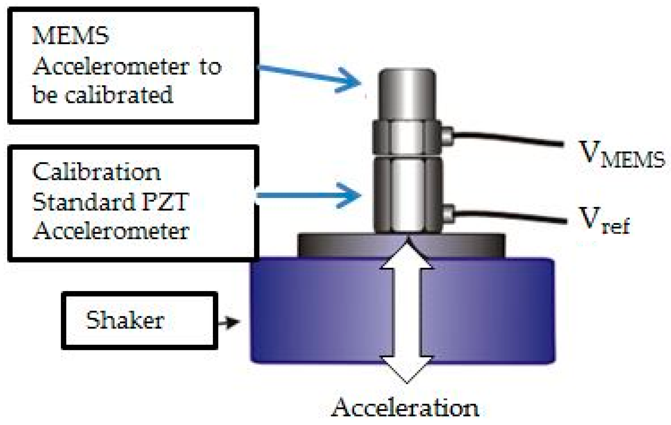
According to ISO-16063-21 [17], comparison methods typically entail performing back-to-back measurements according to a reference standard for determining sensitivity, linearity, and frequency response. The testing MEMS sensor is mounted in a back-to-back arrangement with a standard reference PZT accelerometer, as shown in Figure 5. Because the motion inputs are the same for both devices, the ratio of their outputs is also the ratio of their sensitivities; thus, the sensitivity of the MEMS accelerometer can be calculated. Both sensors can be mounted on an electrodynamic shaker driven by sinusoidal vibration sweeping through the desired range of frequencies, to generate a frequency response curve for the MEMS accelerometer.

Figure 5.
The back-to-back calibration method. PZT: lead zirconate titanate; VMEMS: the output voltage of MEMS accelerometer; Vref: the output voltage of reference PZT accelerometer.
3.2. Testing of Linearity and Frequency Response
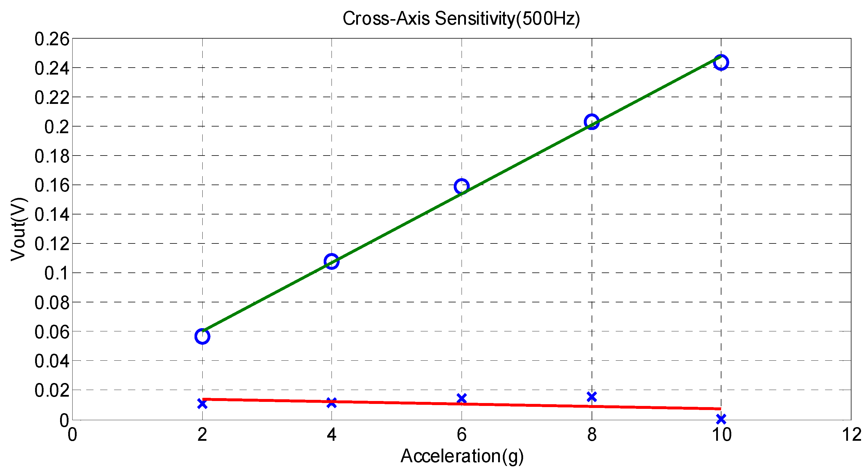
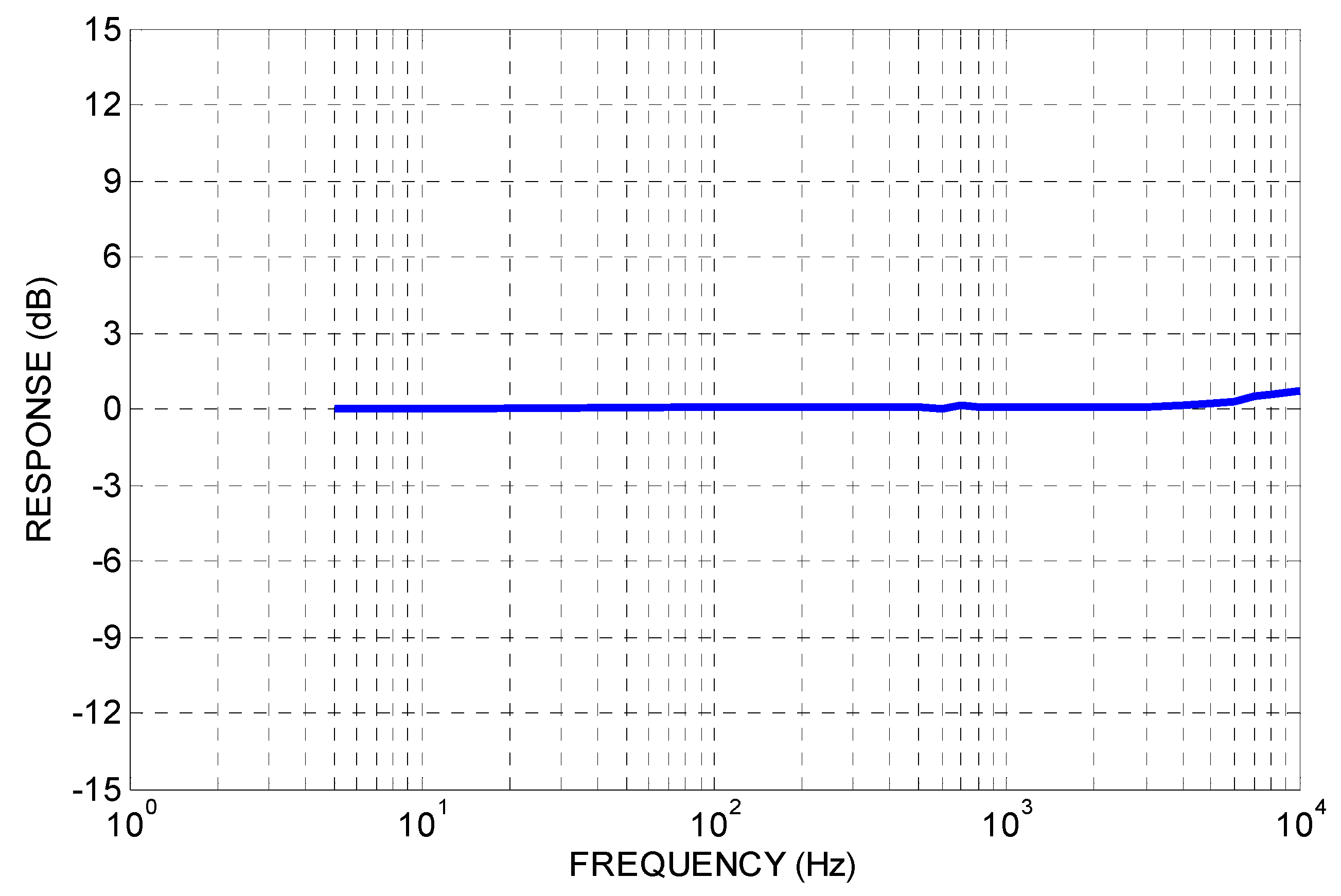
As mentioned in the previous section, the PCB Model 353B15 was used as a standard reference PZT accelerometer. The test platform was fixed on the shaker (PCB type: 4810, New York, NY, USA), which is driven by a function generator (INSTEK AFG-2105, Taipei, Taiwan) and power amplifier (HP MT-1000, Palo Alto, CA, USA). The voltage output signals are recorded in LABVIEW auto-sweep programs by using a data acquisition card (NI 9234). The linearity and frequency response of the packaged MEMS accelerometer can be measured using the back-to-back calibration system. The linearity and cross-axis sensitivity characteristics of the MEMS accelerometer at 500 Hz are shown in Figure 6, where the slope denotes the measured sensitivity. As shown in Figure 6, the slope is 24.7 mV/g, which is close to the sensitivity of the ADXL001 accelerometer, 24.5 mV/g, listed in the data sheet [16], with the maximum deviation of 0.003. The result of the frequency response is shown in Figure 7. Compared with that in Figure 1, the frequency response ranging from 10 Hz to 10 kHz is flatter because of the addition of a low-pass RC filter.
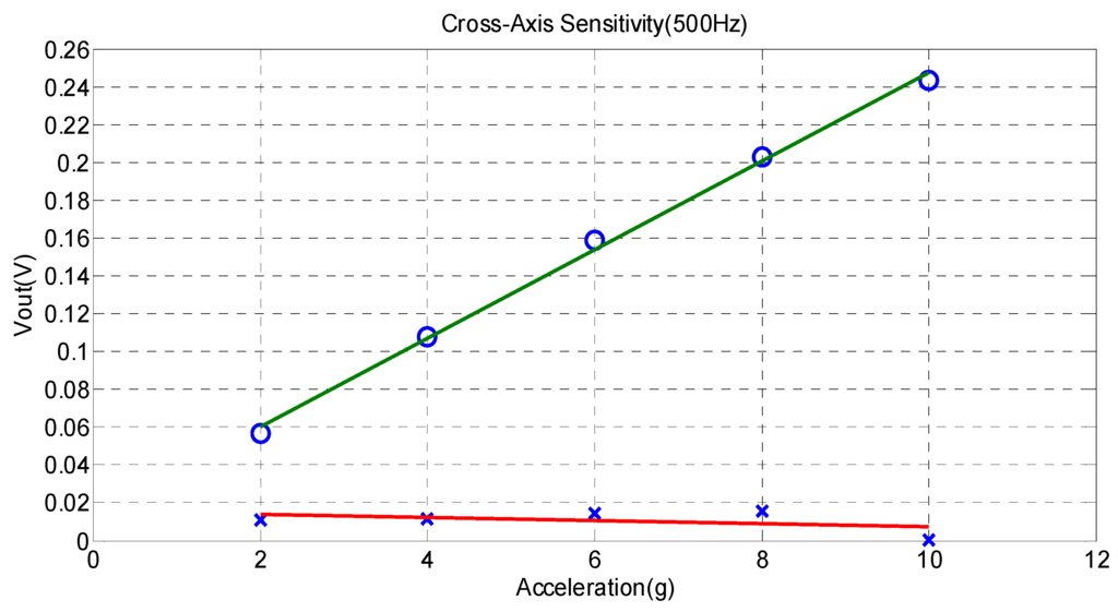
Figure 6.
The linearity character and cross-axis sensitivity of MEMS accelerometers at 500 Hz.

Figure 7.
The frequency response of the MEMS accelerometer.
4. Results and Discussion of the Cutting Experiment
To verify the performance of the MEMS accelerometers, in addition to calibration methods, a three-axis milling machine was used to perform the cutting experiment for comparing the differences between the MEMS- and PZT-type accelerometers. The cutting tool was a four-flute tungsten steel end mill with diameter of 16 mm. The workpiece was comprised of aluminum alloy 6061. The packaged MEMS and PZT (PCB 353B15) accelerometers were pasted to the spindle. The output signals were recorded in the time and frequency domains by using LABVIEW programs and a data acquisition card (NI 9234) with a sample rate of 20 kHz. The arrangement of the cutting experiment is shown in Figure 8. In the cutting experiment, two conditions were tested: steady cutting, and chatter-generated cutting.
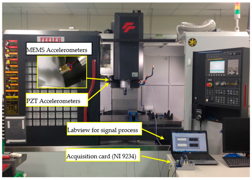
Figure 8.
The arrangement of cutting experiment, including the dual-axis MEMS accelerometer, two PZT (PCB 353B15) accelerometers, the data acquisition card (NI 9234) and the Labview programs for signal process.
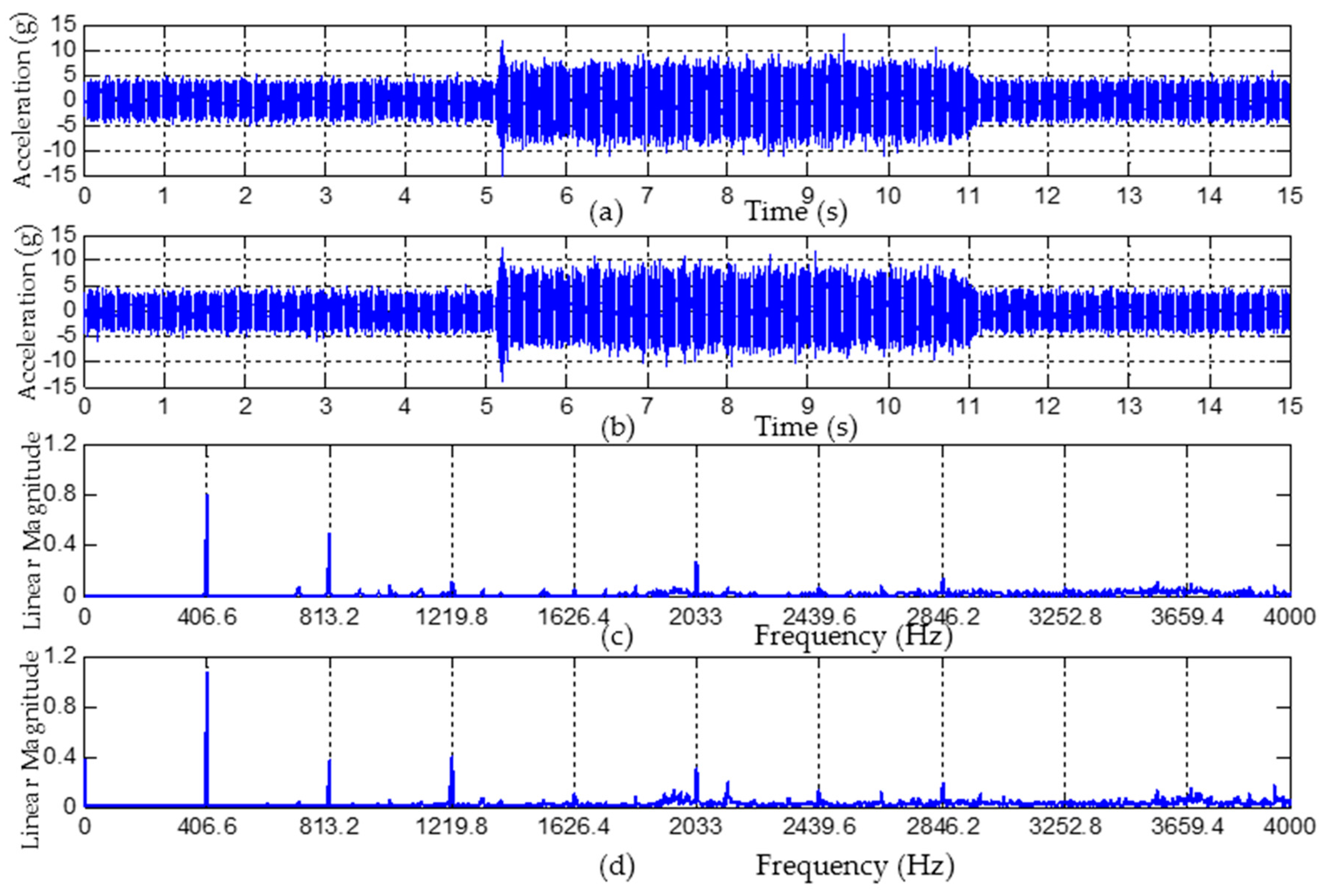
The conditions of steady cutting were as follows: rotational speed of 6100 rpm, feed rate of 2400 mm/min, cutting depth of 10 mm and tooth-passing frequency (TPF) of 406.67 Hz. The result of steady cutting is shown in Figure 9. In the time domain, the real cutting processes started with 5.1 s and stopped with 11.2 s. The acceleration of the PZT and MEMS accelerometers were shown in Figure 9a,b, the average amplitudes of acceleration were approximately 8 g. The results of the PZT and MEMS accelerometers in the frequency domain were shown in Figure 9c,d. In order to facilitate observed characteristics, the X-axes tickets and grids were presented with tooth-pass frequencies. The PZT and MEMS accelerometers produced the same peak values with matching the tooth-pass frequencies.

Figure 9.
The results of steady cutting process by using PZT and MEMS accelerometers. (a) Time domain response of PZT type; (b) Time domain response of MEMS type; (c) Frequency response of PZT type; (d) Frequency response of MEMS type.
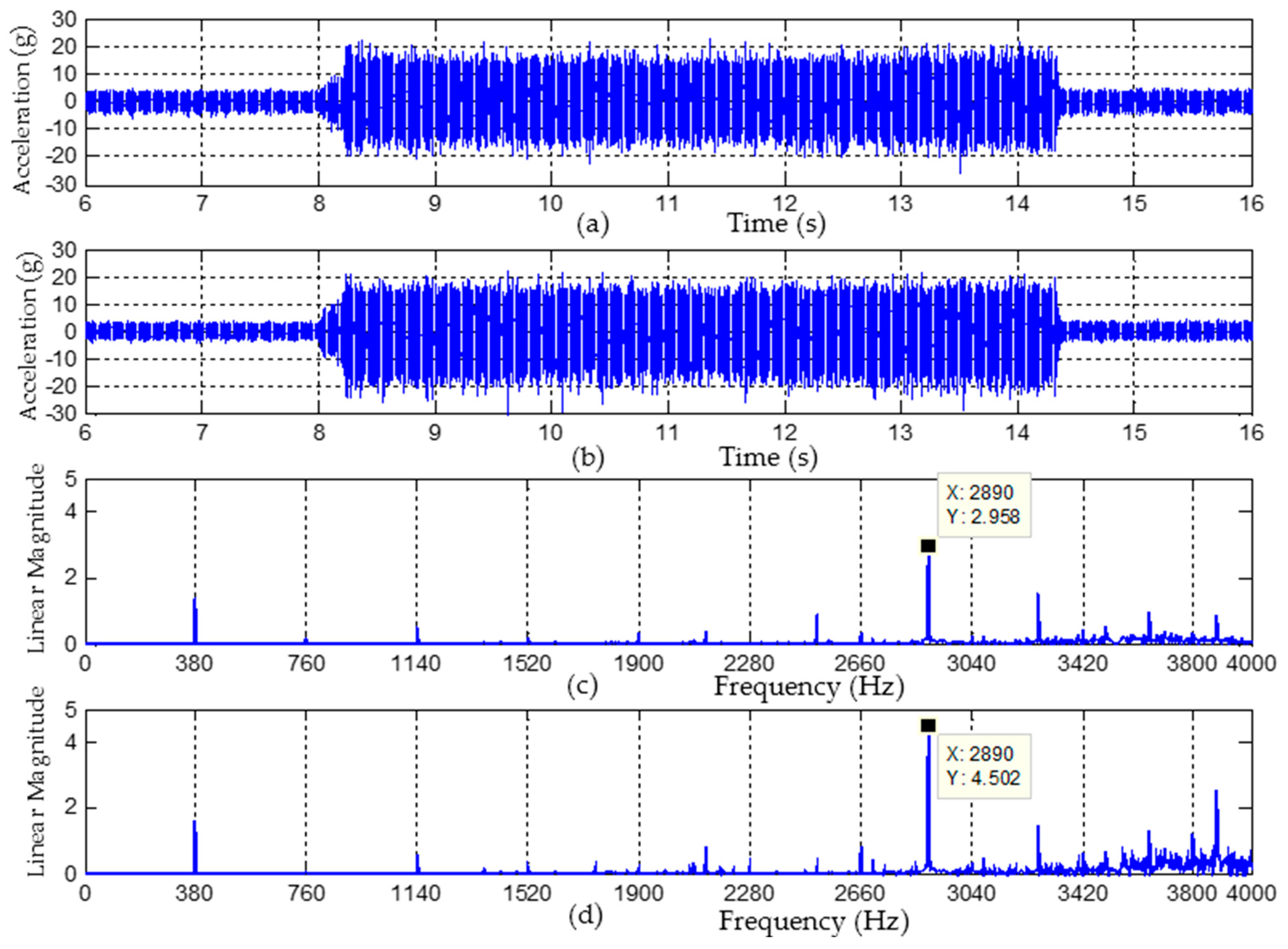
The conditions of chatter-generated cutting were as followed: rotational speed of 5700 rpm, feed rate of 2280 mm/min, cutting depth of 10 mm and tooth passing frequency of 380 Hz. The result of chatter-generated cutting is shown in Figure 10. In the time domain, the real cutting processes started with 8 s, the chatter-generated with 8.2 s, and finished with 14.3 s. The acceleration of the PZT and MEMS accelerometers was shown in Figure 10a,b. The average amplitudes of acceleration during chatter processes were approximately 19 g, higher than that of the steady cutting. The results of the PZT and MEMS accelerometers in the frequency domain were shown in Figure 10c,d; the X-axes tickets and grids were also presented with tooth-pass frequencies. In the frequency domain, the MEMS and PZT accelerometers produced the same peak frequencies. Besides tooth-pass frequencies, chatter frequencies were also monitored. Notably, in the process of chatter-generated cutting, chatter frequencies increased as the vibration was raised, not the tooth-pass frequencies. In addition, in this case, the detected major frequency of chatter was approximately 2890 Hz.
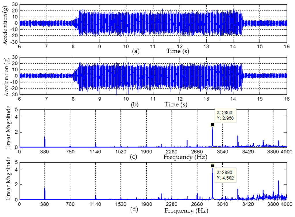
Figure 10.
The results of chatter cutting process by using PZT and MEMS accelerometers. (a) Time domain response of PZT type; (b) Time domain response of MEMS type; (c) Frequency response of PZT type (■: the main chatter frequency); (d) Frequency response of MEMS type (■: the main chatter frequency).
Table 1 is shown to compare the measurements of the cutting experiment according to time and frequency domain between the PTZ and MEMS accelerometers. As shown in Table 1, the measurement values in the time domain of the MEMS accelerometers are larger than those of PZT accelerometers with a variation of less than 6%. This variation may result from the different attachment location of the spindle. Nonetheless, the peak values in the frequency domain of these two accelerometers are the same.

Table 1.
The comparison of measurements in time and frequency domain between piezoelectric and MEMS accelerometers in cutting experiment. PZT: lead zirconate titanate; MEMS: micro electro mechanical systems; TPF: tooth-passing frequency.
In the above cutting experiment, the performance levels of the MEMS and PZT (PCB 353B15) accelerometers were highly similar in time and frequency response, under steady cutting or chatter. The PCB 353B15 is a uniaxial accelerometer with a bandwidth of 10 kHz, a full-scale range of ±500 g, a sensitivity of 10.83 mV/g, and a cost of about $800. In general, accelerometers are regularly used to monitor the vibration and chatter during cutting processes, thereby satisfying the specifications of a 5 kHz bandwidth and a full-scale range of ±40 g. In this study, we developed a dual-axis accelerometer with a bandwidth of 5 kHz, a full-scale range of ±50 g, a sensitivity of 24.8 mV/g, and a cost of only about $80.
5. Conclusions
Dual-axis MEMS accelerometers were successfully developed by considering low-pass filter circuits and housing design. The feasibility was validated using calibration and cutting experiments. In the calibration test, the characteristics of linearity, cross-axis sensitivity and frequency response of the MEMS accelerometer were proved to be excellent. In the process of the cutting experiment, the performance levels of the MEMS- and PZT-type accelerometers were highly similar in time and frequency response, under steady cutting or chatter. The advantage of the newly designed dual-axis MEMS accelerometer is the low cost, which is approximately one-tenth of that of the PZT-type accelerometer.
In the future, we can integrate MEMS accelerometers and embed a system for implementing a module of online intelligent vibration detection.
Acknowledgments
The authors would like to acknowledge the support of FAIR FRIEND ENTERPRISE GROUP, Taiwan.
Author Contributions
Chih-Yung Huang contributed to the organization of the research work, including the experimental configuration, compensation module and manuscript preparation. Jian-Hao Chen contributed to the experiment measurements and data analysis.
Conflicts of Interest
The authors declare no conflict of interest.
References
- Sarhan, A.A.D.; Matsubara, A. Investigation about the characterization of machine tool spindle stiffness for intelligent CNC end milling. Robot. Comput.-Integr. Manuf. 2015, 34, 133–139. [Google Scholar] [CrossRef]
- Du, Z.C.; Zhang, S.J.; Hong, M.S. Development of a multi-step measuring method for motion accuracy of NC machine tools based on cross grid encoder. Int. J. Mach. Tools Manuf. 2009, 49, 99–108. [Google Scholar] [CrossRef]
- Chen, J.-S. Intelligent machine tool technology. ROC Autom. Technol. Soc. J. 2008, 34, 66–72. [Google Scholar]
- Gao, R.; Zhang, L. Micromachined microsensors for manufacturing. IEEE Instrum. Meas. Mag. 2004, 7, 20–26. [Google Scholar] [CrossRef]
- Mitsuishi, M.; Warisawa, S.; Hanayama, R. Development of an intelligent high-speed machining center. Ann. CIRP 2001, 50, 275–280. [Google Scholar] [CrossRef]
- Vijayaraghavan, A.; Dornfeld, D. Automated energy monitoring of machine tools. CIRP Ann. Manuf. Technol. 2010, 59, 21–24. [Google Scholar] [CrossRef]
- Bhattacharyya, K.; Pal, S.K.; Patra, K. Artificial neural network based prediction of drill flank wear from motor current signals. Appl. Soft Comput. 2007, 7, 929–935. [Google Scholar]
- Bhattacharyya, P.; Mukhopadhyay, S.; Sengupta, D. Cutting force-based real-time estimation of tool wear in face milling using a combination of signal processing techniques. Mech. Syst. Signal Process. 2007, 21, 2665–2683. [Google Scholar] [CrossRef]
- Ramesh, R.; Mannan, M.A.; Poo, A.N. Error compensation in machine tools—A review part I: Geometric, cutting-force induced and fixture dependent errors. Int. J. Mach. Tools Manuf. 2000, 40, 1235–1256. [Google Scholar] [CrossRef]
- Jerard, R.B.; Xu, M.; Fussell, B.K. Cutting Power Model-Sensor Integration for Tool Condition Monitoring. In Proceedings of the International Conference on Smart Machining Systems, NIST, Gaithersburg, MD, USA, 13–15 March 2007.
- Teti, R.; Jemielniak, K.; O’Donnell, G.; Dornfeld, D. Advanced monitoring of machine operations. CIRP Ann. Manuf. Technol. 2010, 50, 717–739. [Google Scholar] [CrossRef]
- Dimla, E.; Dimla, S. Sensor signals for tool-wear monitoring in metal cutting operations—A review of methods. Int. J. Mach.Tools Manuf. 2000, 40, 1073–1098. [Google Scholar] [CrossRef]
- Kuljanic, E.; Sortino, M.; Totis, G. Development of an intelligent multisensory chatter detection system in milling. Mech. Syst. Signal Process. 2009, 2, 1704–1718. [Google Scholar] [CrossRef]
- Cus, F.; Zuperl, U. Tool cutting force modelling in ball-end milling using multilevel perceptron. J. Mater. Process. Technol. 2004, 153–154, 268–275. [Google Scholar]
- Yao, Z.; Mei, D.; Chen, Z. On-line chatter detection and identification based on wavelet and support vector machine. J. Mater. Process. Technol. 2010, 210, 713–719. [Google Scholar] [CrossRef]
- Analog Devices. ADXL001 Data Sheet; Analog Devices Inc.: Norwood, MA, USA, 2008. [Google Scholar]
- ISO 16063-21, Methods for the Calibration of Vibration and Shock Transducers-Part 21: Vibration Calibration by Comparison to a Reference Transducer. Available online: http://www.iso.org/iso/iso_catalogue/catalogue_tc/catalogue_detail.htm?csnumber=27053 (accessed on 7 July 2016).
- ISO 16063-1, Methods for the Calibration of Vibration and Shock Transducers, Part 1: Basic Concepts. Available online: http://www.iso.org/iso/catalogue_detail.htm?csnumber=25043 (accessed on 7 July 2016).


© 2016 by the authors; licensee MDPI, Basel, Switzerland. This article is an open access article distributed under the terms and conditions of the Creative Commons Attribution (CC-BY) license (http://creativecommons.org/licenses/by/4.0/).