Article

Generation of 25-TW Femtosecond Laser Pulses at 515 nm with Extremely High Temporal Contrast

1
Helmholtz Institute Jena, Fröbelstieg 3, 07743 Jena, Germany
2
Institute of Optics and Quantum Electronics, Friedrich-Schiller-University Jena, Max-Wien Platz 1, 07743 Jena, Germany
*
Author to whom correspondence should be addressed.
Appl. Sci. 2015, 5(4), 1970-1979; https://doi.org/10.3390/app5041970
Submission received: 7 September 2015 / Revised: 4 December 2015 / Accepted: 14 December 2015 / Published: 19 December 2015
(This article belongs to the Special Issue Diode-Pumped, Ultra-Short Pulse Lasers)

Abstract

:
We report on the frequency doubling of femtosecond laser pulses at 1030 nm center wavelength generated from the fully diode-pumped laser system POLARIS. The newly generated pulses at a center wavelength of 515 nm have a pulse energy of 3 J with a pulse duration of 120 fs. On the basis of initially ultra-high contrast seed pulses we expect a temporal intensity contrast better 10 17 200 ps before the peak of the main pulse. We analyzed the temporal intensity contrast from milliseconds to femtoseconds with a dynamic range covering more than 20 orders of magnitude. The pulses were focussed with a f/2-focussing parabola resulting in a peak intensity exceeding 10 20 W / cm 2 . The peak power and intensity are to the best of our knowledge the highest values for 515 nm-laser-pulses achieved so far.

1. Introduction

In laser science a rapid progress in generating laser pulses with peak intensities exceeding 10 22 W / cm 2 could be witnessed over the past decades [1]. These laser pulses are used for a variety of applications, e.g., laser-driven electron [2,3] or ion-acceleration [4], the laser-based generation of x-rays [5], high energy physics [6] or laser-based proton radiography [4,7].
Most of these applications would strongly benefit or even ultimately require laser pulses with a well known temporal structure and a temporal intensity contrast as high as possible. Unfortunately the amplification of high power laser pulses in reality is always associated with the amplification of unwanted noise or pre- and post-pulses on different intensity- and time-scales [8]. Since these pre- and post-pulses significantly alter the experimental conditions a lot of effort is put into improving the temporal intensity contrast [9,10]. Commonly used techniques within the laser systems are, e.g., saturable absorbers [11], or OPCPA [12], Double-CPA [13] including XPW [14]. The application of such techniques results in very high contrast laser pulses with temporal intensity contrast ratios of 10 12 or better [9,10,15]. Even those high contrast laser pulses are, however, not sufficient for some experimental applications, e.g., radiation pressure acceleration of ions [16] where a steep leading edge of the laser pulse is required for nm-scale thin targets. Further improvement of the temporal pulse quality is necessary and could be realized after the pulse compression, e.g., with plasma mirrors [17], plasma shutters [18] or by generating the second harmonic [19,20,21].
In this paper we present experimental results of the second harmonic generation (SHG) of 100-TW POLARIS [10] laser pulses centered at 1030 nm wavelength and 150 fs pulse duration. Using a 2 mm thin 160 mm-diameter potassium dihydrogen phosphate (KDP) type-I SHG-crystal we achieved a maximum pulse energy of 3 J with a pulse duration of 120 fs at 515 nm center wavelength. A detailed characterization of the newly generated laser pulses’ temporal structure is presented from ms- to fs-timescales covering a dynamic range of more than 20 orders of magnitude for the focussed intensity. Due to the used wavelength separators for 1030 nm and 515 nm and the nonlinearity of the second harmonic generation, the laser pulses’ temporal profile for the target interaction is shortened and contrast-enhanced. The results were obtained during a five-month experimental campaign starting at the end of 2014. In this experiment, ultra-thin targets (down to 5 nm) were used to study radiation pressure acceleration of protons with high intensity laser pulses.

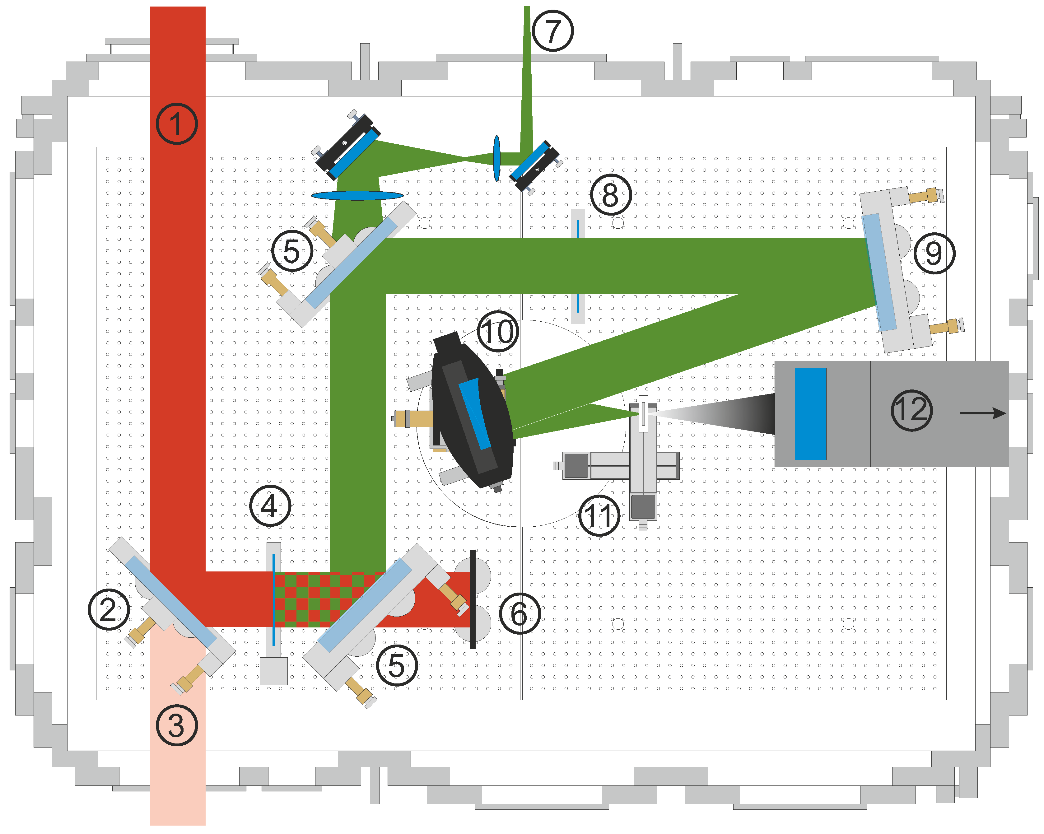
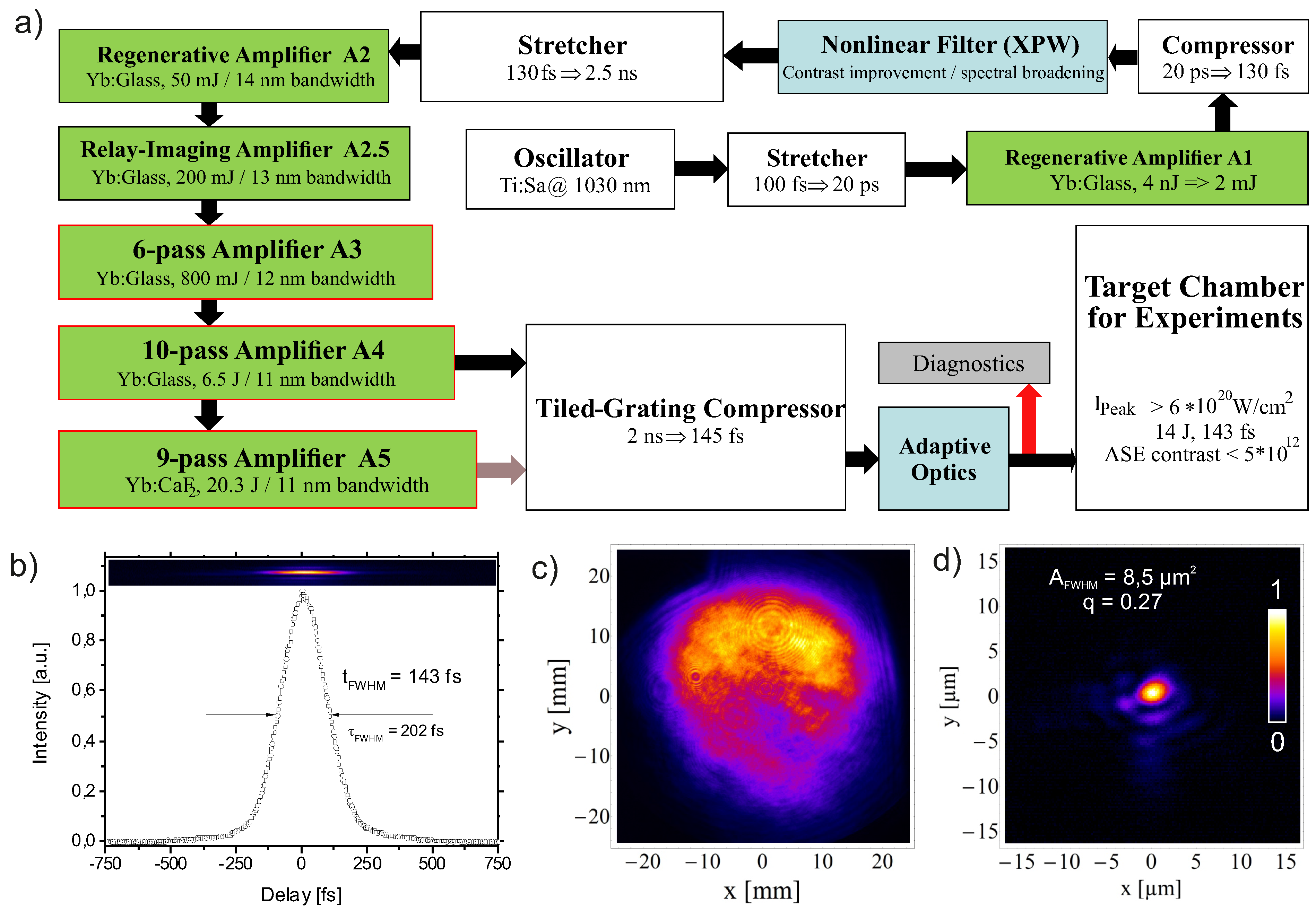
2. Experimental Section
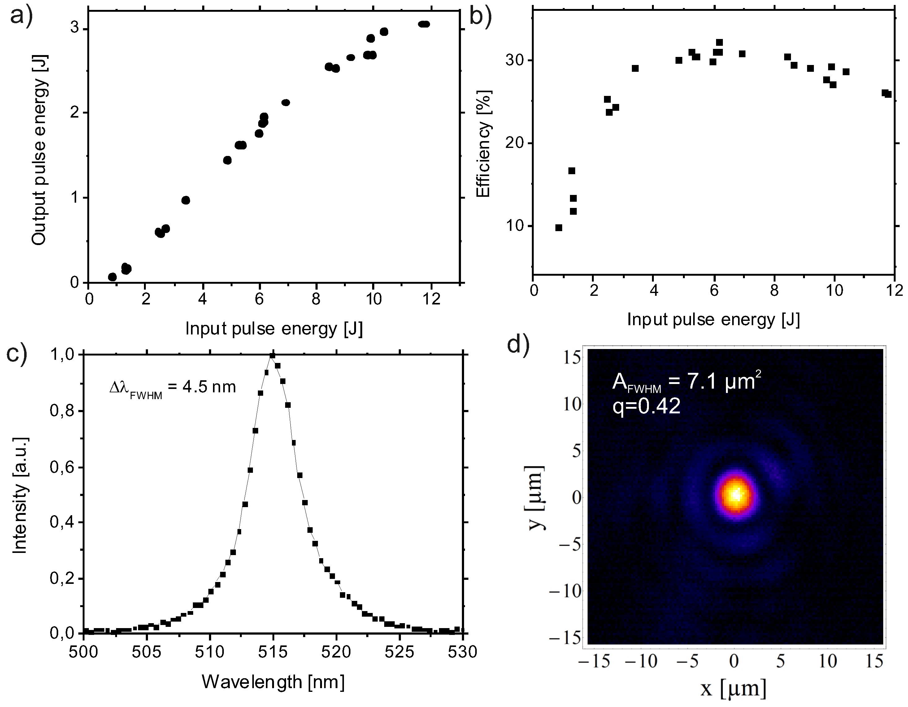
The experiments were carried out with the fully diode-pumped POLARIS laser system operational at the Helmholtz-Institute and the Institute of Optics and Quantum Electronics in Jena, Germany. A schematic overview of the laser architecture is shown in Figure 1a). During the experiments the laser used a high-contrast XPW front end where the relative intensity of the amplified spontaneous emission (ASE) 200 ps before the peak of the main pulse was as low as 2 × 10 13 with respect to the main pulse intensity. A detailed description of the XPW front end, which was used at an intensity of 9 × 10 11 W / cm 2 and was operated reaching an XPW-efficiency of 13%, can be found in [22]. Six amplifiers and a nanosecond stretcher-compressor system are used to amplify and compress the laser pulses where a detailed description can be found in [10].
Figure 1. Setup and measurements of POLARIS. (a) Schematic setup. The system uses six amplifier and two stretcher-compressor stages to finally deliver 14 J pulse energy in 143 fs pulse duration on target; (b) Second-order autocorrelation measurement of the compressed A5-pulses. The upper inset displays the spatially resolved autocorrelation signal; (c) Measured near-field profile of the final amplifier with an output energy of 20.3 J; (d) Measured transverse far-field profile of the A5-amplified pulses. The area within which the intensity is larger than I max / 2 is 8.5 μ m 2 and contains 27 % of the pulse energy (q = 0.27).
Applsci 05 01970 g001
Additionally to the results presented in [10] we installed a beam line from the last amplifier A5 to the existing pulse compressor [23]. Here, the pulses were compressed to a full width at half maximum (FWHM) pulse duration of t pulse = 143 fs assuming a Gaussian pulse shape. In Figure 1b) the 2 nd -order autocorrelation measurement is shown which was performed with a home-made 2 nd -order autocorrelator, where the pulse is focused in one dimension into a BBO-crystal using a cylindrical lens. The inset in Figure 1b) displays the spatially resolved autocorrelation signal. During the experiments we achieved a maximum pulse energy of E pulse = 20 . 3 J (measured before compression) and 14 J in the target chamber with a measured transmission efficiency of η = 69 % of the grating compressor. The near-field profile is displayed in Figure 1c). The repetition rate f Rep was limited by the pump induced thermal load in the active media of the last two amplifiers and therefore set to f Rep = 0 . 025 H z ( f Rep = 0.1 Hz for A3, 0.5 Hz for A2.5 and 1 Hz for A1 and A2). Finally, the pulses were focussed in the target chamber with a f/2-focussing parabola (f = 300 mm). In Figure 1d) an image of the focal spot is shown. The adaptive mirror was set to correct the static wavefront aberrations of the beamline and laser optics. In this measurement the wavefront was flattened with an adaptive optics system and the pulses were strongly attenuated in the laser chain. The area within which the intensity is larger than I max / 2 is 8.5 μ m 2 and contains 27 % of the pulse energy (q = 0.27). q gives the ratio of pulse energy which is contained within the area where the intensity is larger than I max / 2 ( A FWHM ) with respect to the total pulse energy. These pulses were used in the following experiments for the second harmonic generation.

2.1. SHG Setup

To increase the temporal contrast of the pulses a 160 mm-diameter, 2 mm-thick potassium dihydrogen phosphate crystal (KDP) was used to convert the 1030 nm wavelength pulses to 515 nm. A schematic setup of the experimental layout is depicted in Figure 2.
Figure 2. Schematic setup of the second harmonic generation and subsequent proton acceleration experiment in the POLARIS target chamber. ① Input laser pulse. ② Turning mirror. ③ Diagnostic leakage light. ④ KDP-crystal. ⑤ Wavelength separator. ⑥ Beam dump. ⑦ SHG focus diagnostic. ⑧ Quarter-wave plate. ⑨ Turning mirror. ⑩ Focussing parabola. ⑪ Target. ⑫ Proton diagnostics.
Applsci 05 01970 g002
The incoming laser pulse is reflected to the KDP-crystal (Figure 2 ④) by a turning mirror, where the leakage (Figure 2 ③) is used with a far-field diagnostic to act a as a reference for the beam direction for the experiments. The KDP crystal which was manufactured by Gooch & Housego (Highland Heights, OH, USA) has a crystal-cut angle of 41 ° for type-I phase matching. For optimal long-term and laser performance the input surface was solgel antireflection-coated for 1030 nm and the output surface for 515 nm and 1030 nm. The polarization of the fundamental pulses is parallel to the horizontal plane in the target chamber and the newly generated SHG-pulses are polarized vertically. In order to separate the fundamental pulses from the SHG pulses two high quality wavelength separators (Figure 2 ⑤) were installed between the KDP-crystal and the focusing parabola. These wavelength separators are 250 mm diameter, 45 ° angle of incidence turning mirrors with a high reflectivity (R > 99.9%) for the SHG-pulses at 515 nm and a low reflectivity (R < 0.1%) for the fundamental pulses at 1030 nm. Using two of these mirrors, which were manufactured by Layertec (Mellingen, Germany), the fundamental pulses could be attenuated by 6 orders of magnitude which was measured with an energy meter behind the focusing parabola. In front of the focusing parabola a 500 μm thin fused silica plate with an AR-coating (R < 0.75%) for the 515 nm pulses was used as a debris shield. Behind the second wavelength separator a f/2-focussing optic (Figure 2 ⑦) was installed to measure the full energy 515 nm focal spot during the experiments utilizing the leakage. Furthermore, a quarter-wave plate could be installed in the beam line in order to change between circular and linear polarization in the experiments.

3. Results and Discussion

The crystal was prealigned in air for most efficient frequency conversion using the frontend A2-amplified pulses with a repetition rate of 1 Hz. With the far-field diagnostic and the adaptive optics system the collimation of the A2-pulses could be adapted to the fully amplified pulses. After this prealignment the target chamber was evacuated and the fully amplified pulses were used to adjust the crystal rotation with the aim of maximum output energy. It was found that the crystal rotation needed to be aligned with better than 1 mrad accuracy. In Figure 3a) the dependence of the output energy on the input energy is shown. In this measurement we achieved a maximum pulse energy of 3.05 J for an input pulse energy of 11.8 J.
For this pulse, we measured a maximum fluence of 200 mJ / cm 2 in the fundamental pulse, which results in a conversion efficiency of η = 26%. Corresponding to the tuning curve in Figure 3a the efficiency was calculated and depicted in Figure 3b. The maximum conversion efficiency slightly above 30% was achieved for pulse energies betweeen 6 J and 8 J. Compared to work of other groups (e.g., Hillier et al. [21, η = 75%) the efficiency we have measured is barely the half of such an optimal value. With an otherwise identical but small size (5 mm aperture) KDP crystal we measured the efficiency for the conversion of TEM 00 -spatial pulses resulting in a maximum efficiency of 38% at comparable intensities. To the best of our knowledge, the comparatively low conversion efficiency may be caused by effects of the cubic nonlinearity, which are explained in detail in [24], and the limited phase matching due to the crystal thickness of 2 mm. Furthermore, imperfections in the crystal, deviations of the wavefront from ideal flatness, back conversion and the non-ideal spatial and temporal beam profile of the fully amplified laser pulses (ideal temporal and spatial profile for SHG would be a flat-top profile) are contributing.
Figure 3. Measurements of the second harmonic generation (SHG) pulses. (a) Output (515 nm) versus input (1030 nm) energy; (b) Efficiency as a function of input pulse energy; (c) Spectral intensity distribution; (d) Transverse far-field profile. The area within which the intensity is larger than I max / 2 is 7.1 μ m 2 and contains 42 % of the pulse energy (q = 0.42).
Applsci 05 01970 g003
However, the moderate efficiency in our experiment is part of ongoing research and will likely be improved in the future. Measures for improvement will comprise a homogenization of the near-field profile of the IR-beam and a flattening of the IR-wave front. Currently the latter is optimized to generate a minimal focal spot in the IR, which is not necessarily equivalent to a flat IR-wavefront at the position of the frequency doubling crystal. Furthermore, tests with crystals of different thickness will be carried out.
In Figure 3c a typical spectral intensity distribution is shown for a full energy shot. The spectrum was measured with an integrating sphere and shows a FWHM spectral width of 4.5 nm around the center wavelength of 515 nm. To verify the pulse duration we built a single-shot 2nd-order autocorrelator for 515 nm pulses. Since it was not possible to install the correlator in the experimental area we measured the pulse duration with the aforementioned identical small size KDP-sample. In these measurements we have observed that the frequency doubled pulse duration is a factor of 2 shortened with respect to the initial pulse duration. This fits well to theory and we assume a pulse duration below 120 fs for the high-energy frequency doubled pulses.
Furthermore, during the high-energy laser shots we have measured the focal spot of the frequency doubled pulses with a high-quality f/2-imaging system (Figure 2 ⑦). In Figure 3d the spatial distribution in the focal plane of the green laser pulses is shown. The calibration represents the size of the focal spot behind the main focussing parabola. The adaptive optics system was used to flatten the wavefront of the 1030 nm pulses. The area within which the intensity is larger than I max / 2 ( A FWHM ) is 7.1 μ m 2 and contains 42 % of the pulse energy. Assuming a pulse energy of 3 J in a pulse duration of 120 fs leads to a peak intensity of 3 × 10 20 W / cm 2 which was applied to the targets.

Temporal Pulse Structure
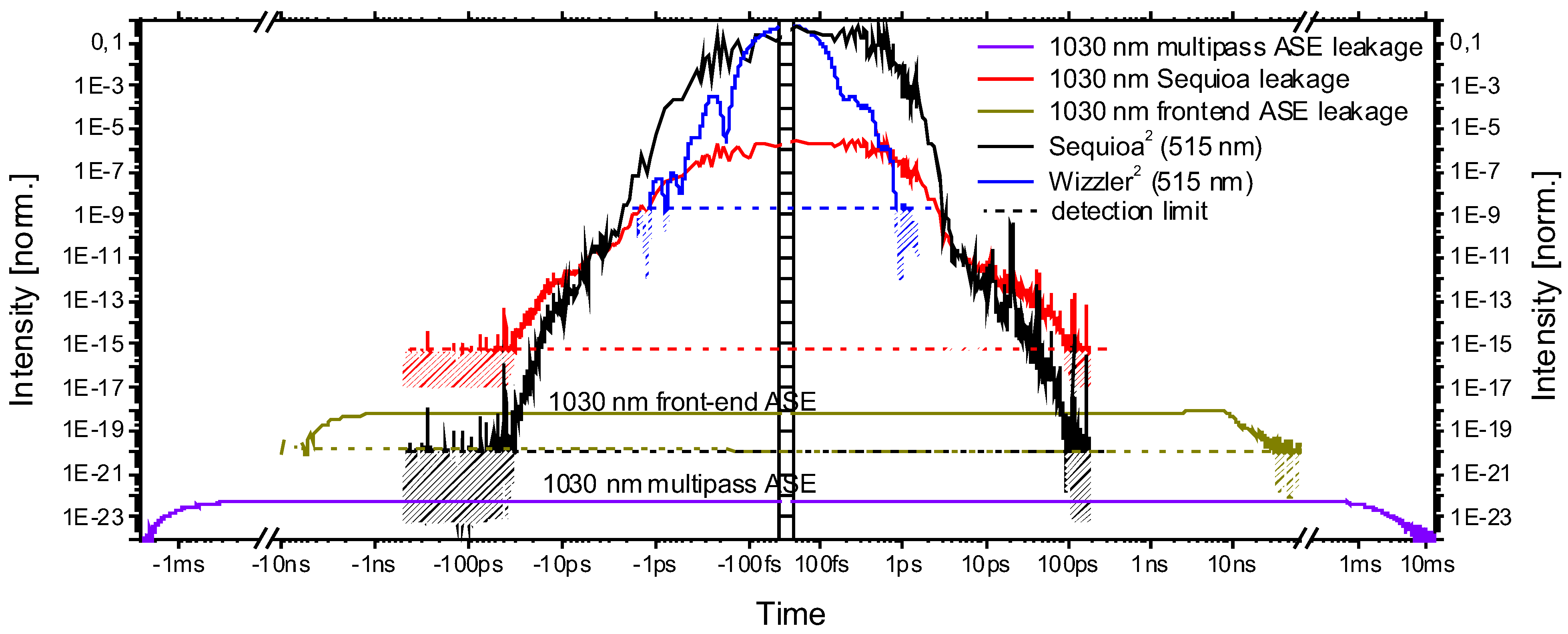
In Figure 4 an overview of the temporal pulse structure of the SHG-pulses is shown in a log-log representation of focussed intensity vs. time. The starting point was a measurement carried out for the 1030 nm-pulses of POLARIS. We want to point out that the measurement method leading to Figure 4 is described in detail in [25] and the experimental data for the used 1030 nm laser pulses are published in section 6 of [10].
Figure 4. Measured and calculated temporal characterization of the on target intensity taking SHG and fundamental pulses into account. Negative times are defined as the times before the laser pulse. Black: converted THG-correlation for 515 nm. Blue: converted self-referenced spectral interferometry (Wizzler, Fastlite) measurement for 515 nm. Red: converted THG-correlation for 1030 nm. Ocher: Converted photodiode measurement for the 1030 nm frontend amplified spontaneous emission (ASE). Dark blue: Converted photodiode measurement for the 1030 nm multipass ASE. The detection limit of each measurement is marked as a dashed line.
Applsci 05 01970 g004
To estimate the on-target temporal intensity contrast we have to take two influences into account. Firstly the temporal contrast of the SHG-pulses and secondly the temporal contrast of the fundamental beam.
The black curve in Figure 4 displays the intensity of the SHG-pulses on a ps-timescale and was calculated by taking the square of a cross-correlation measurement (Sequoia, Amplitude) of the fundamental pulses. Due to the SHG, which is a 2 nd -order nonlinear process, the intensity of the newly generated signal is the square of the input and this conversion is acceptable. An identical conversion was made with a self-referenced spectral interferometer (SRSI, Wizzler, Fastlite) measurement and is shown in the blue curve. Note that the measurement with the Sequoia is taken in the near-field of the compressed pulse and since we are using a tiled-grating compressor some spectral components of the pulses are missing depending on the lateral position in the laser pulse. This may lead to a smaller relative intensity contrast for the laser pulse (and its leading edge) as compared to the contrast in the focal spot where the pulses are applied in experiments [10]. Summarizing this argument means that the temporal region ± 1 . 5 ps around the main pulse is likely better represented by the SRSI-measurement. For the sake of completeness we note that the SHG signal of the POLARIS frontend and multipass ASE is far below the intensity range in Figure 4.
Using a collinear type-I phase matching SHG the fundamental beam co-propagates with the SHG-pulses and could only be attenuated stepwise. For the attenuation we used two wavelength separators (cf. Section 2.1) with a total extinction ratio of 1 × 10 6 . Taking into account the pulse duration, the focal spot size and the energy loss of the fundamental beam during the SHG we calculated a peak intensity reduction of 1 × 10 5 for the attenuated fundamental beam with respect to the focussed SHG-pulses. The attenuated fundamental beam is displayed in Figure 4 with three different curves. At first the multipass ASE (dark blue) starting on a ms-timescale before the main pulse with a relative intensity of 10 22 , secondly the frontend ASE (ocher) starting some ns before the main pulse with an intensity level of some 10 18 and finally the main pulse (red) measured with a third-order correlator (Sequoia, Amplitude). Note that the detection limit in the red curve is reached ≈100 ps before the main pulse and all three curves are normalized to the maximum peak intensity of the SHG-pulses.
It is obvious in Figure 4 that on ms- and ns-timescales the ASE of the fundamental pulse determines the temporal intensity contrast to values better 10 17 until the leading edge of the fundamental pulse and the SHG-pulse ≈100 ps before the main pulse plays the dominant role. Since, however, this 1030 nm leakage can be further suppressed, e.g., by using an additional dichroic mirror, it is not a fundamental intrinsic contrast limit for the SHG laser pulses.

4. Conclusions

In conclusion we have performed the frequency doubling of 100 TW POLARIS laser pulses with initially ultra-high temporal contrast. We have analyzed the temporal pulse structure in detail for several orders of magnitude in time and intensity. Using a large-aperture type-I KDP crystal we generated 25 TW laser pulses at a wavelength of 515 nm which were focussed to peak intensities exceeding 10 20 W / cm 2 . With an efficiency of 26 % a maximum pulse energy of 3 J in 120 fs pulse duration could be demonstrated. Due to the initially ultra-high temporal contrast of POLARIS we expect a temporal intensity contrast 200 ps before the main pulse better 10 17 . This is to the best of our knowledge the highest value reported for frequency doubled pulses. The presented setup was used in an experimental campaign for proton acceleration and could be used for future experiments which require ultra-high contrast laser pulses for plasma physics.

Acknowledgments

The research leading to these results has received funding from LASERLAB-EUROPE (grant agreement n ° 284464, EC’s Seventh Framework Programme) and from the Bundesministerium für Bildung und Forschung (BMBF) (03ZIK445 and 03Z1H531).
We acknowledge Marco Hellwing and Frank Schorcht for excellent laser operation, Peter Hilz for providing the setup for the spectrum and Stephan Kuschel for fruitful discussions regarding the setup.

Author Contributions

M.H., G.A.B., A.S., J.R., H.L., L.B., S.K. and A.K. performed the experiment and evaluated the data; M.H., J.H., M.Z. and M.C.K. supervised the experiment; M.H. and M.C.K. wrote the manuscript.

Conflicts of Interest

The authors declare no conflict of interest.

References

  1. Danson, C.; Hillier, D.; Hopps, N.; Neely, D. Petawatt class lasers worldwide. HP Laser Sci. Eng. 2015, 3, e3. [Google Scholar] [CrossRef]
  2. Esarey, E.; Schroeder, C.B.; Leemans, W.P. Physics of laser-driven plasma-based electron accelerators. Rev. Mod. Phys. 2009, 81, 1229–1285. [Google Scholar] [CrossRef]
  3. Kim, H.T.; Pae, K.H.; Cha, H.J.; Kim, I.J.; Yu, T.J.; Sung, J.H.; Lee, S.K.; Jeong, T.M.; Lee, J. Enhancement of Electron Energy to the Multi-GeV Regime by a Dual-Stage Laser-Wakefield Accelerator Pumped by Petawatt Laser Pulses. Phys. Rev. Lett. 2013, 111, 165002–165006. [Google Scholar] [CrossRef] [PubMed]
  4. Macchi, A.; Borghesi, M.; Passoni, M. Ion acceleration by superintense laser-plasma interaction. Rev. Mod. Phys. 2013, 85, 751–793. [Google Scholar] [CrossRef]
  5. Corde, S.; Phuoc, K.T.; Beck, A.; Lambert, G.; Fitour, R.; Lefebvre, E.; Malka, V.; Rousse, A. Femtosecond x-rays from laser-plasma accelerators. Rev. Mod. Phys. 2013, 85, 1–58. [Google Scholar] [CrossRef]
  6. Izawa, Y.; Miyanaga, N.; Kawanaka, J.; Yamakawa, K. High Power Lasers and Their New Applications. J. Opt. Soc. Korea 2008, 12, 178–185. [Google Scholar] [CrossRef]
  7. Johnston, H. Five spin-offs from physics research with the potential to change our lives: Physics for our future. Phys. World 2013, 26, 50–53. [Google Scholar] [CrossRef]
  8. Keppler, S.; Sävert, A.; Körner, J.; Liebetrau, H.; Hornung, M.; Hein, J.; Kaluza, M.C. The generation of amplified spontaneous emission in high-power CPA laser systems. Laser Photonics Rev. 2015. [Google Scholar] [CrossRef]
  9. Danson, C.; Neely, D.; Hillier, D. Pulse fidelity in ultra-high-power (petawatt class) laser systems. HP Laser Sci. Eng. 2014, 2, e34. [Google Scholar] [CrossRef]
  10. Hornung, M.; Liebetrau, H.; Seidel, A.; Keppler, S.; Kessler, A.; Körner, J.; Hellwing, M.; Schorcht, F.; Klöpfel, D.; Arunachalam, A.K.; et al. The all-diode-pumped laser system POLARIS—An experimentalist’s tool generating ultra-high contrast pulses with high energy. HP Laser Sci. Eng. 2014, 2, e20. [Google Scholar] [CrossRef]
  11. Itatani, J.; Faure, J.; Nantel, M.; Mourou, G.; Watanabe, S. Suppression of the amplified spontaneous emission in chirped-pulse-amplification lasers by clean high-energy seed-pulse injection. Opt. Commun. 1998, 148, 70–74. [Google Scholar] [CrossRef]
  12. Yoshida, H.; Ishii, E.; Kodama, R.; Fujita, H.; Kitagawa, Y.; Izawa, Y.; Yamanaka, T. High-power and high-contrast optical parametric chirped pulse amplification in β-BaB2O4 crystal. Opt. Lett. 2003, 28, 257–259. [Google Scholar] [CrossRef] [PubMed]
  13. Kalashnikov, M.P.; Risse, E.; Schönnagel, H.; Sandner, W. Double chirped-pulse-amplification laser: A way to clean pulses temporally. Opt. Lett. 2005, 30, 923–925. [Google Scholar] [CrossRef] [PubMed]
  14. Jullien, A.; Albert, O.; Burgy, F.; Hamoniaux, G.; Rousseau, J.P.; Chambaret, J.P.; Auge-Rochereau, F.; Cheriaux, G.; Etchepare, J.; Minkovski, N.; et al. 1010 temporal contrast for femtosecond ultraintense lasers by cross-polarized wave generation. Opt. Lett. 2005, 30, 920–922. [Google Scholar] [CrossRef] [PubMed]
  15. Kiriyama, H.; Mori, M.; Pirozhkov, A.S.; Ogura, K.; Sagisaka, A.; Kon, A.; Esirkepov, T.Z.; Hayashi, Y.; Kotaki, H.; Kanasaki, M.; et al. High-Contrast, High-Intensity Petawatt-Class Laser and Applications. IEEE J. Sel. Topics Quantum Electron. 2015, 21, Article No. 1601117. [Google Scholar] [CrossRef]
  16. Schreiber, J.; Bell, F.; Najmudin, Z. Optimization of relativistic laser-ion acceleration. HP Laser 2014, 2, e41. [Google Scholar] [CrossRef]
  17. Kapteyn, H.C.; Murnane, M.M.; Szoke, A.; Falcone, R.W. Prepulse energy suppression for high-energy ultrashort pulses using self-induced plasma shuttering. Opt. Lett. 1992, 16, 490–492. [Google Scholar] [CrossRef]
  18. Reed, S.A.; Matsuoka, T.; Bulanov, S.; Tampo, M.; Chvykov, V.; Kalintchenko, G.; Rousseau, P.; Yanovsky, V.; Kodama, R.; Litzenberg, D.W.; et al. Relativistic plasma shutter for ultraintense laser pulses. Appl. Phys. Lett. 2009, 94, Article No. 201117. [Google Scholar] [CrossRef] [PubMed]
  19. Chien, C.Y.; Korn, G.; Coe, J.S.; Squier, J.; Mourou, G.; Craxton, R.S. Highly efficient second-harmonic generation of ultraintense Nd: Glass laser pulses. Opt. Lett. 1995, 20, 353–355. [Google Scholar] [CrossRef] [PubMed]
  20. Queneuille, J.; Druon, F.; Maksimchuk, A.; Cheriaux, G.; Mourou, G.; Nemoto, K. Second-harmonic generation and wave-front correction of a terawatt laser system. Opt. Lett. 2000, 25, 508–510. [Google Scholar] [CrossRef] [PubMed]
  21. Hillier, D.; Danson, C.; Duffield, S.; Egan, D.; Elsmere, S.; Girling, M.; Harvey, E.; Hopps, N.; Norman, M.; Parker, S.; et al. Ultrahigh contrast from a frequency-doubled chirped-pulse-amplification beamline. Appl. Opt. 2013, 52, 4258–4263. [Google Scholar] [CrossRef] [PubMed]
  22. Liebetrau, H.; Hornung, M.; Seidel, A.; Hellwing, M.; Kessler, A.; Keppler, S.; Schorcht, F.; Hein, J.; Kaluza, M.C. Ultra-high contrast frontend for high peak power fs-lasers at 1030 nm. Opt. Express 2014, 22, 24776–24786. [Google Scholar] [CrossRef] [PubMed]
  23. Kessler, A.; Hornung, M.; Keppler, S.; Schorcht, F.; Hellwing, M.; Liebetrau, H.; Körner, J.; Sävert, A.; Siebold, M.; Schnepp, M.; et al. 16.6 J chirped femtosecond laser pulses from a diode-pumped Yb:CaF2 amplifier. Opt. Lett. 2014, 39, 1333–1336. [Google Scholar] [CrossRef] [PubMed]
  24. Ditmire, T.; Rubenchik, A.M.; Eimerl, D.; Perry, M.D. Effects of cubic nonlinearity on frequency doubling of high-power laser pulses. JOSA B 1996, 13, 649–655. [Google Scholar] [CrossRef]
  25. Keppler, S.; Hornung, M.; Bödefeld, R.; Sävert, A.; Liebetrau, H.; Hein, J.; Kaluza, M.C. Full characterization of the amplified spontaneous emission from a diode-pumped high-power laser system. Opt. Express 2014, 22, 11228–11235. [Google Scholar] [CrossRef] [PubMed]

