1. Introduction
Seismic resistant systems such as special and ordinary moment-resisting connection frames have often been designed to generate considerable plastic deformations in the main frame members (
i.e., beams and columns) under strong earthquakes [
1,
2,
3], in spite of providing more stiffness to resist lateral loads. These plastic deformations may result in serious trouble in the repair of not only structural damage but also residual drifts [
4,
5,
6]. The conventional steel slit dampers employed in such seismic resistant systems have been widely used as easy-to-replace energy dissipation devices because they are designed to allow the concentration of inelastic deformations for the purpose of protecting the main frame members. This design approach can make significant improvement regarding safety and economy, and can also improve acceptable seismic performance. Although these steel energy-dissipating dampers do improve damage control and member protection, their permanent deformation under strong earthquakes can bring about unexpected residual inter-story drifts in the entire building frame [
5,
7,
8]. In addition, extra costs are necessary to replace dampers that have been damaged beyond repair with new ones. A recent study found that the owners of residential buildings in Japan would be better advised to rebuild entire structures rather than repair them when maximum residual inter-story drifts are greater than 0.5% [
9]. Therefore, additional seismic restrainers combined in parallel to the retrofit energy dissipation damper should be required for aseismic design achieved by supplementing strength and stiffness to the structure with the aim of reducing inter-story drifts.
One of the best ways to ameliorate seismic performance with respect to vibration control and recentering capability is accomplished by applying smart materials to the damper system [
4,
10,
11,
12,
13,
14,
15,
16,
17]. Superelastic shape memory alloys (SMAs) have been widely utilized for self-centering and passive vibration control devices on the grounds that they possess their own material behavior characterized as a flag-shaped hysteresis under cyclic loading [
17,
18,
19,
20]. In this study, bending bars fabricated with superelastic SMAs are installed on the steel slit damper and aligned vertically. The superelastic SMA bending bars, acting as seismic restrainers, instantly supply self-centering forces to the integrated damper system, and thus contribute to reducing permanent deformations mainly attributed to plastic yielding on the steel slit damper. Besides the reinforcing effects attained by these bending bars, energy dissipation capacities demanded for seismic resistance and supplemental damping are further improved in the cyclic behavior of the integrated damper system.
The steel slit dampers presented here are designed based on experimental models provided in the reference [
21]. The analytical specimens treated in this study are classified according to the types of steel slit dampers and the installation of the SMA bending bars. For the concept of the pilot study (so-called pre-study), this paper mainly focused on the inelastic behavior of new recentering damper systems, which was reproduced by refined three dimensional (3D) finite element (FE) analyses without relevant experimental tests. The FE models for steel slit dampers are calibrated to experimental results for the purpose of validating the adequacy of 3D FE modeling. After completing FE analyses, both models compared to each other are evaluated in aspects of seismic performance, such as ultimate strength, permanent deformation, and recentering ratio. The analysis results indicate that superelastic SMA bending bars sufficiently redeem the slit damper system from damage by improving performance and capacity. Finally, stress and strain curves measured at the critical points are also displayed as compared with the behavior of steel and SMA materials in order to verify reliable prediction.
2. Superelastic SMA Materials
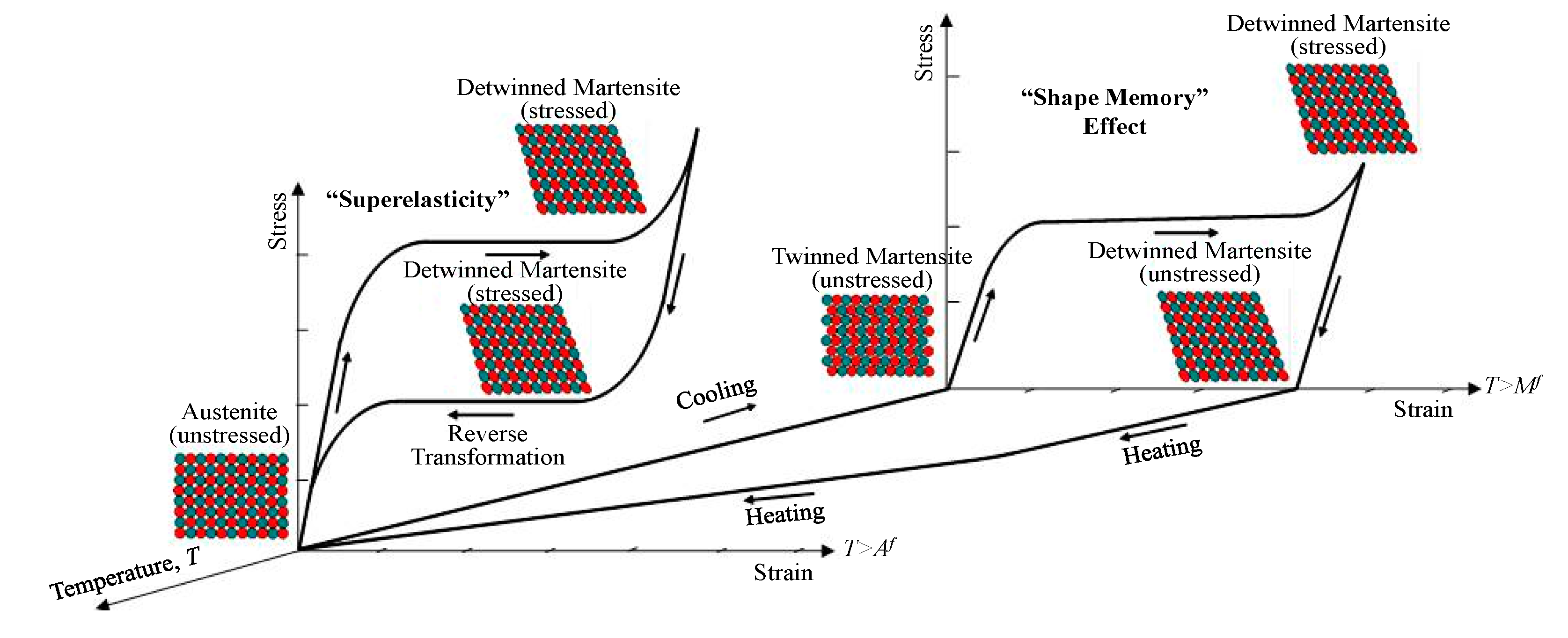
The behavior of typical SMA materials (e.g., nickel-titanium metallic alloys, so called Nitinol), which is plotted as the stress-strain-temperature relationship, is shown in
Figure 1. The SMA materials exhibit two crystal phases,
i.e., (a) weaker martensite phase, and (b) stronger austenite phase [
19,
22,
23]. These crystal phases account for their unique physical properties known as shape memory effect (SME) and superelastic effect (SE). The SME is easily found at the martensite phase, which mostly appears at a low temperature. Conversely, the SE is easily detected at the austenite phase, which is stable at a high temperature. The SME can be described as a material’s ability to regain its original shape upon heating while the SE describes a material’s distinct capability to recover its original configuration from large deformation just after the removal of the applied load [
22,
23,
24].
Figure 1.
Behavior of superelastic shape memory alloy (SMA) materials according to phase transformation.
Figure 1.
Behavior of superelastic shape memory alloy (SMA) materials according to phase transformation.
As can be seen in
Figure 1, SMA materials exhibit the SME under the temperature below the martensite finishing temperature (
Mf). The behavior of martensitic phase SMA materials can accommodate a considerable amount of plastic strain arising due to the low stress plateau, and then display a large value for residual strain upon unloading. Once SMA materials are heated above the austenite finishing temperature
(Af), they begin to recover their original shape from residual strain. It is because the phase transformation from weak detwinned martensite to strong body-centered austenite occurs during heat treatment. The SMA materials go back to twinned martensite upon cooling, thereby completing one cycle of phase transformation owing to the SME [
22]. On the other hand, superelastic behavior, referred to as a flag-shape hysteretic loop having almost zero-residual strain, appears at a temperature greater than
Af. The austenitic phase SMAs subjected to a range of up to 8% strain are capable of fully recovering their original shape [
23]. The austenitic phase SMAs at the flag-shaped hysteresis curve exhibit higher stress-leveled slip plateaus than the martensitic phase SMAs. The phase transformation converted from austenite to stress-induced martensite takes place along the path of the slip plateau. Even when constant temperatures are maintained, the stress-induced reverse transformation back to the austenite phase that causes the SE occurs upon unloading.
Superelastic SMAs, owing to their ideal properties, are particularly good examples of promising smart materials in the engineering field. The damper systems retrofitted with superelastic SMAs are expected to benefit from recentering capability, guaranteed by the SE and supplemental damping attributed to energy dissipation. The stress slip plateau in the flag-shape hysteresis helps to limit force transmission at the intermediate strain level [
25,
26]. Furthermore, these materials include excellent corrosion resistance as well as outstanding fatigue strength [
22]. Once superelastic SMA bending bars are installed to be integrated with steel slit dampers, we expect that the equipped structures will make the best use of SMA material’s unique properties. In this paper, the effectiveness of the damper system retrofitted with such seismic restrainers will be investigated primarily through nonlinear 3D FE analyses cyclically tested.
3. Slit Damper Models
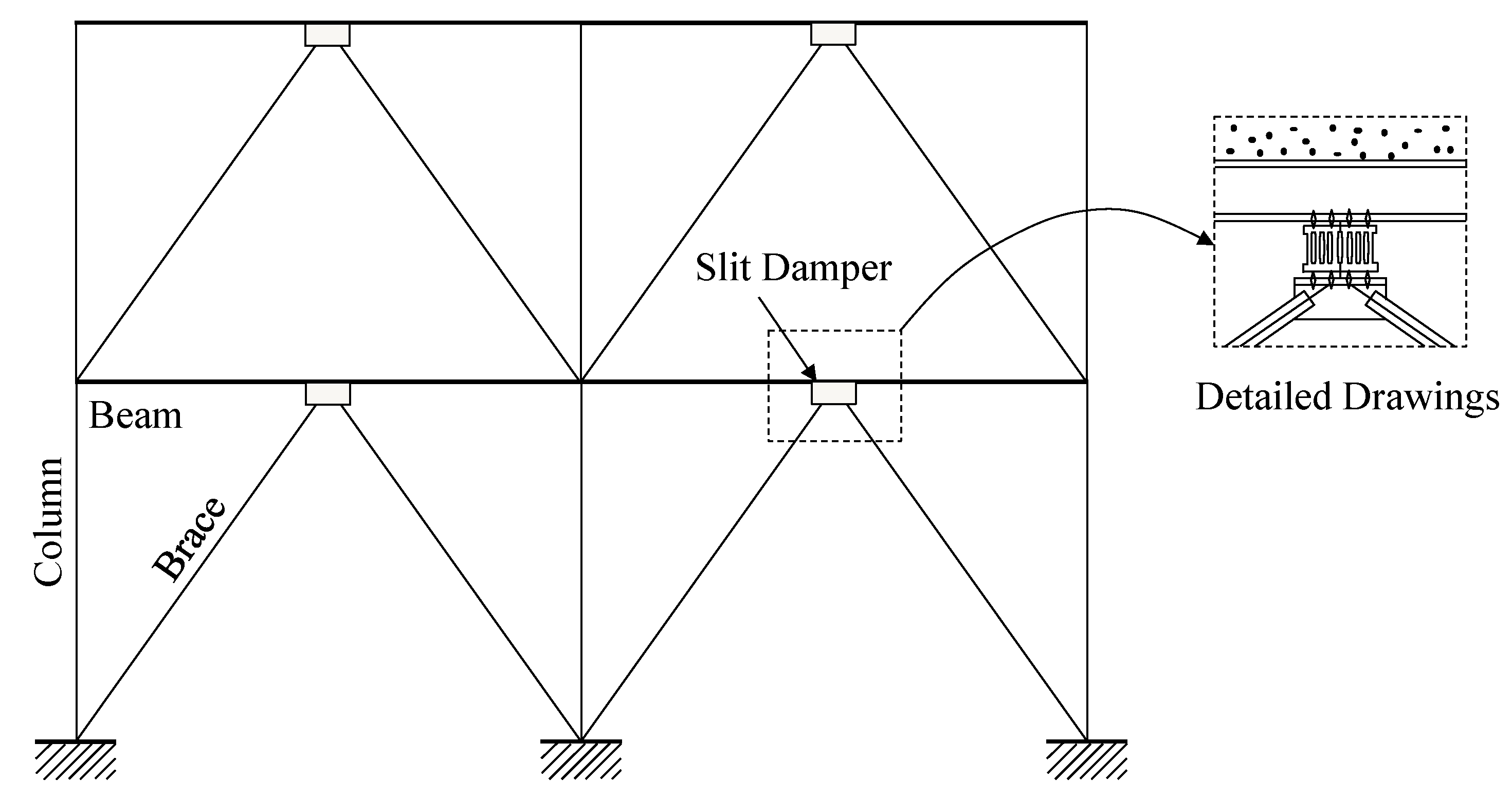
In general, passive energy-dissipating devices have been designed to be incorporated into the bracing system of structural frames. Accordingly, typical steel slit dampers can be installed on the top of chevron-shaped (inverted-V) braces at the concentrically braced frames (CBFs), and attached to the middle of the beam member as shown in
Figure 2. The installation of these devices leads to seismic design philosophy based upon increasing ductility and energy dissipation capacity of all types of frame structures. The geometric details for the slit damper (SL) models provided in the reference [
21] are illustrated in
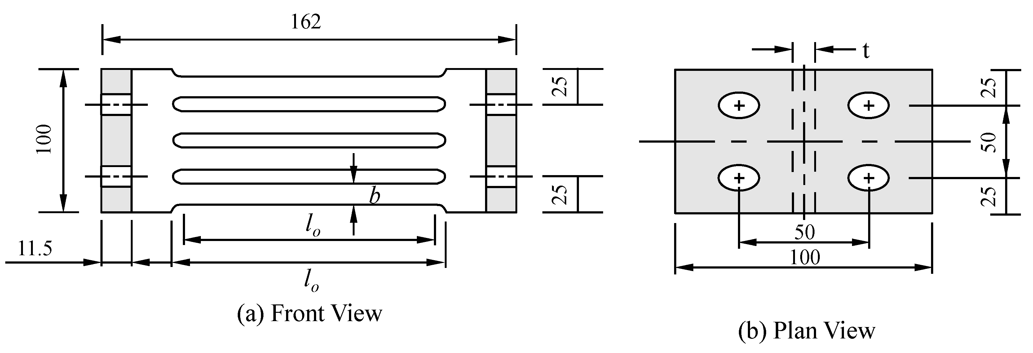
Figure 3. These slit damper models are manufactured from standard wide flange sections with a number of slits cut from the web, thereby leaving a number of strips between two flanges. The slits are rounded at their ends with the aim of avoiding stress concentration in the reentrant corner. The slit dampers are connected to the main frame member with four bolts, thus removing the possibility of sudden failure due to any imperfections associated with welding.
Information on the established specimens for the experimental test performed by Chan and Albermani [
21] is presented in
Table 1. The values of variable design parameters illustrated in
Figure 3 (
i.e.,
lo,
b, and
t) are also presented in this table. In this paper, six experimental specimens out of total nine specimens are selected for parametric study. In addition, the 3D FE models used to reproduce the behavior of the slit dampers are calibrated to their experimental test results so as to validate the propriety of the modeling methods. The standard wide flange section with the dimension of 161.8 mm depth by 152.2 mm flange width by 8mm for web thickness by 11.5 mm for flange thickness was used to construct all slit damper specimens. The standard base material coupons were obtained from the web section. After conducting coupon tests to determine material properties, yield stress, elastic modulus, and hardening ratio were determined to be 316.5 MPa, 206.1 GPa, and 1.5%, respectively. In general, Grade (Gr.) 50 carbon steel includes these material property values. The slit damper specimens labeled from SL1 to SL6 in the table can be classified as having
b/lo ratios ranging from 0.155 to 0.215. The slit dampers with superelastic SMA bending bars are labeled as an additional “-SMA” in the last acronym of the model identification (ID), for example, SL1-SMA (see also
Table 1).
Figure 2.
Installation of the slit damper device in the concentrically braced frame.
Figure 2.
Installation of the slit damper device in the concentrically braced frame.
Figure 3.
Geometric details for experimental slit damper (SL) models, (a): Front View, (b): Plan.
Figure 3.
Geometric details for experimental slit damper (SL) models, (a): Front View, (b): Plan.
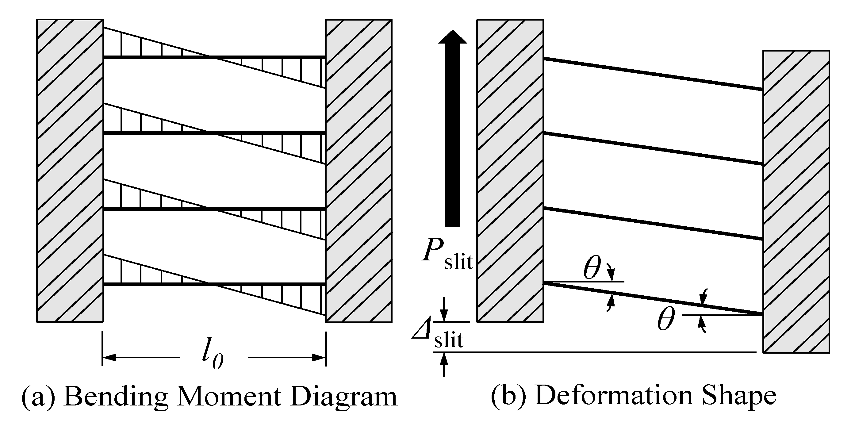
These steel slit dampers withstand shear forces (
Psilt) carried from the beam members, and undergo corresponding shear deformations (Δ
slit). A part of the web sections can be considered as deep beam sections, which deform due to shearing. Meanwhile, the relatively slender strips behave as a series of partially fixed-end beams with rotational angles (θ) at the end supports, and mostly deform in double curvature under bending. Because of rapid section changes at both ends of each strip, plastic hinges attributed to the mechanism of energy dissipation occur under sufficient bending deformation. On the contrary, inflection points characterized by the zero-moment position are generated approximately at the middle of each strip. Including the bending moment diagram drawn along the strip line, the deformation of the slit damper subjected to direct shear force is illustrated in
Figure 4. As can be also seen in
Figure 3, the bending mechanism of the strip can be determined in accordance with design parameters, such as strip depth (
lo), strip width (
b), and web thickness (
t).
Table 1.
Geometric design parameters for experimental slip damper models.
Table 1.
Geometric design parameters for experimental slip damper models.
| Model ID | Measured Dimensions | b/l0 |
|---|
| t | b | l0 |
|---|
| SL1 (SL1-SMA) | 8.0 | 14.9 | 97.0 | 0.155 |
| SL2 (SL2-SMA) | 8.0 | 15.0 | 87.1 | 0.172 |
| SL3 (SL3-SMA) | 8.0 | 15.1 | 77.0 | 0.195 |
| SL4 (SL4-SMA) | 8.0 | 16.9 | 99.2 | 0.172 |
| SL5 (SL5-SMA) | 8.0 | 16.8 | 88.3 | 0.191 |
| SL6 (SL6-SMA) | 8.0 | 16.5 | 79.0 | 0.215 |
Figure 4.
Response mechanism of slit damper models, (a): Bending Moment Diagram, (b): Deformation Shape.
Figure 4.
Response mechanism of slit damper models, (a): Bending Moment Diagram, (b): Deformation Shape.
4. Slit Damper Systems with Recentering SMA Bars
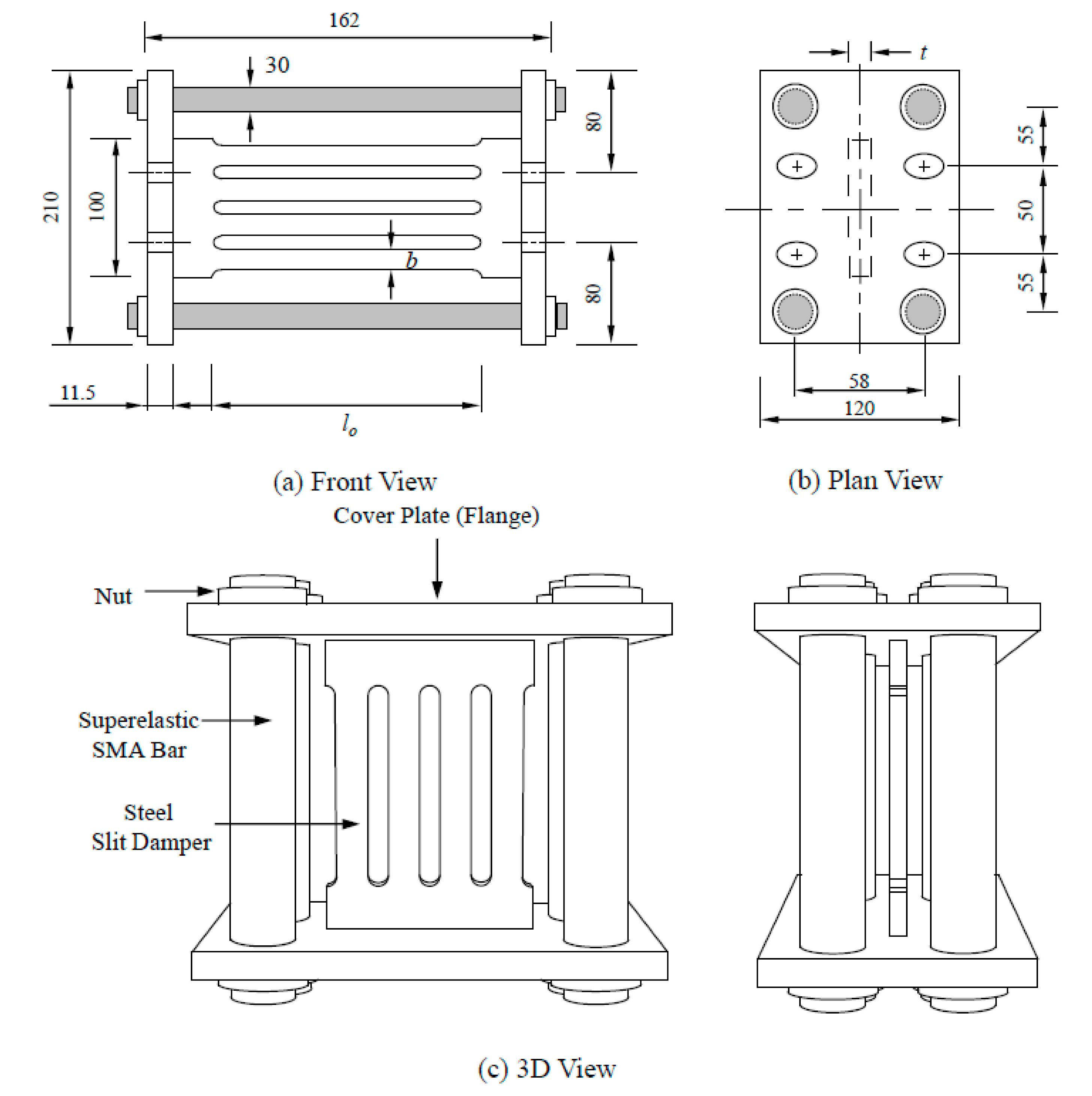
In order to overcome the disadvantage of existing steel damper models, slit damper systems with recentering SMA bars, which are intended to improve self-centering capability, are proposed in this study. The detail drawings for the proposed damper systems are shown in
Figure 5. Four superelastic SMA bars are equipped with the steel slit damper, and connected to both flanges by clamping themselves on the nuts. These superelastic SMA bars, round in shape, can achieve weld-free design for the purpose of avoiding any heat treatment effect. The welding heat applied to superelastic SMA material at room temperature tends to cause the change of the material property, and results in the loss of recentering capability. Furthermore, round section SMA bars offer both stiffness and strength for equally resisting external forces in any direction. The diameters of all SMA bars are a uniform 30 mm so that the same recentering forces are offered to various slit dampers with their different capacities. The steel slit dampers that are identical to experimental specimens presented in
Section 3 are used to construct the proposed damper system.
Figure 5.
Design of the slit damper system with recentering SMA bars (a): Front View; (b): Plan View and (c): 3D View.
Figure 5.
Design of the slit damper system with recentering SMA bars (a): Front View; (b): Plan View and (c): 3D View.
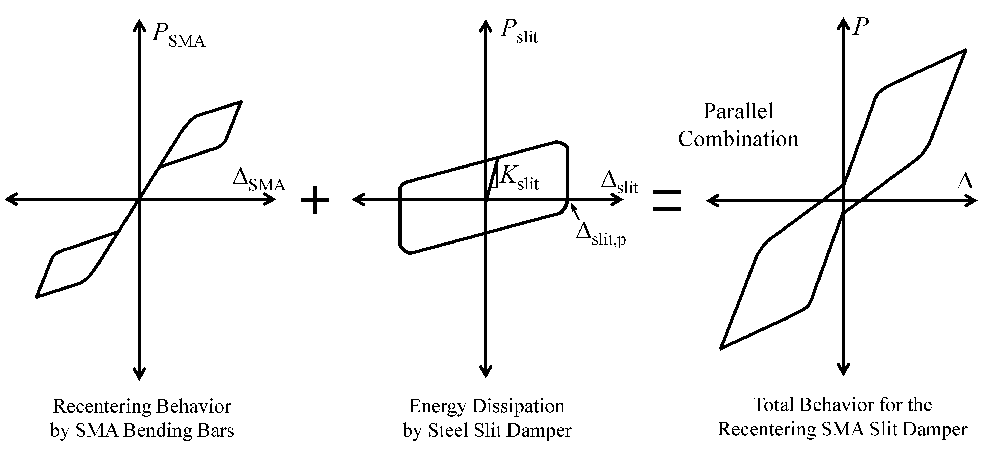
The response mechanism of the recentering slit damper system, which is achieved by the behavior of the steel slit damper and the superelastic SMA bending bars, is presented in
Figure 6. The reverse phase transformation changing from martensite to austenite upon unloading leads in a major way to self-centering behavior, which offers core competence to SMA materials without residual strain at the room temperature. Accordingly, the proposed damper system possesses excellent recentering capability resulting from this unique characteristic referred to as super-elasticity or pseudo-elasticity. The parallelogram hysteresis loop represents stable energy dissipation formed by the yielding of the slender strips. The displacement (or strain) hardening affected by the base material’s property is also involved in this loop. In spite of providing vibration damping to the structure, energy dissipation induced by metallic yielding has a tendency to produce considerable permanent deformation (Δ
slit,p) during cyclic loading. Finally, the total behavior of the recentering slit damper system proposed herein can be simulated by superposing superelastic SMA behavior and energy dissipation behavior. As can be seen in
Figure 6, these component behaviors are assembled in parallel depending on how they interact each other. Owing to such parallel assemblage, the total force of the recentering slit damper system (
P) can be determined by adding together component forces under the corresponding displacement (Δ) as follows:
The amount of permanent deformation in the recentering slit damper system is entirely dependent on recentering force simply regulated by the size of the superelastic SMA bending bars.
Figure 6.
Response mechanism of the recentering slit damper system.
Figure 6.
Response mechanism of the recentering slit damper system.
5. Finite Element (FE) Analysis Models
The ABAQUS nonlinear FE program [
27] was used to predict the behavior of the recentering slit damper devices cyclically tested. The FE models were composed of 3D solid four node elements (
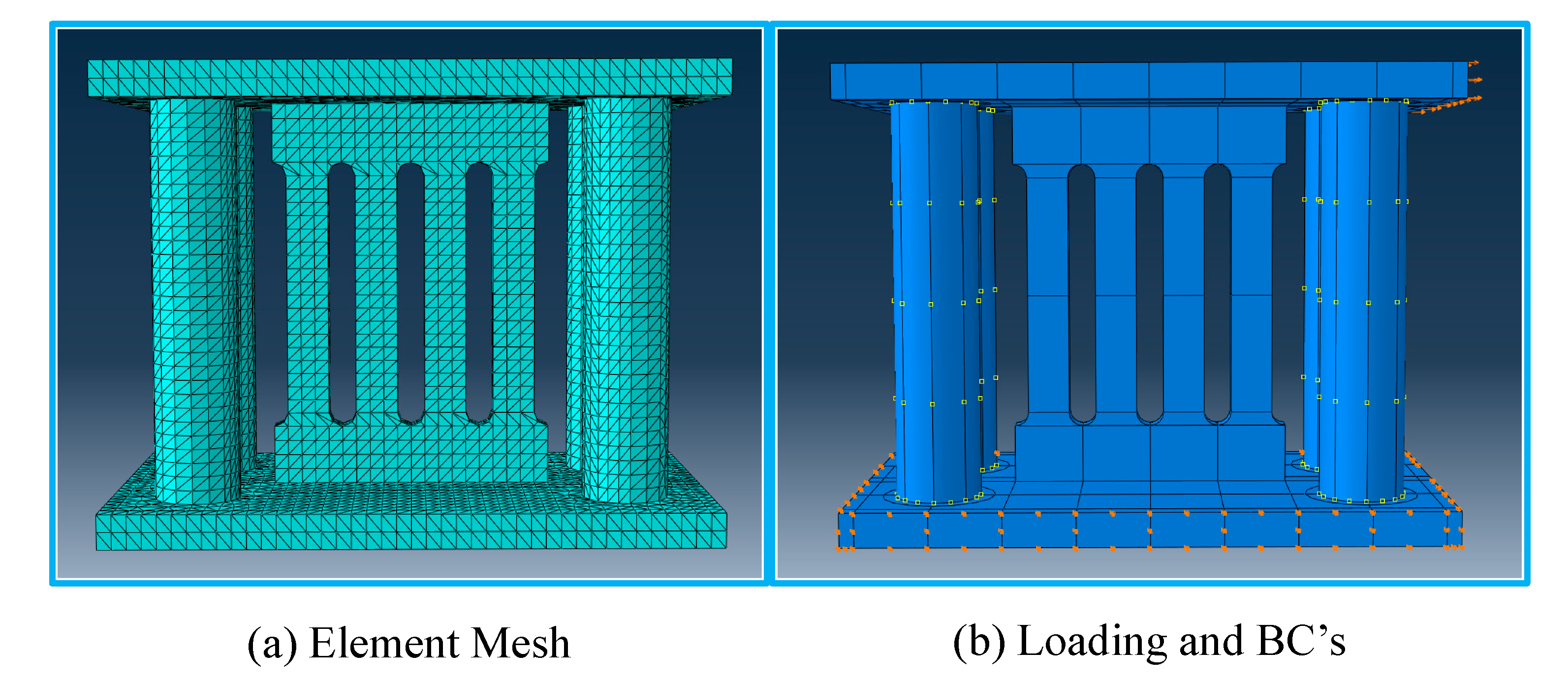
i.e., C3D4 in the ABAQUS program) associated with nonlinear material properties, geometric nonlinearity, and displacement-controlled load histories. The details of 3D FE models such as structural meshes, displacement loading, and boundary conditions (BC’s) are illustrated in
Figure 7. The structural meshes were generated by dividing individual parts so that uniform element sizes required for obtaining convergent results should be constructed in the FE model. The SMA bending bars were assumed to be rigidly connected to the flange of the slit damper without clearance between bolt shanks and bolt holes. Therefore, detail modeling for bolt heads, nuts, and contacted bolt threads could be neglected by merging bolt shank and contacted bolt holes in the flange. The displacement-controlled loads were directly imposed on the edge of the flange. The cyclic load histories for refined quasi-static FE analyses were reproduced by using amplitude functions incorporating the static step. The FE analyses were conducted with the same loading history as the experimental slit damper tests (
Figure 13a).
The nonlinear material properties were aligned to individual parts made up of the solid elements. The isotropic/kinematic hardening material model containing the Bauschinger effect, plastic shakedown, ratcheting and stress relaxation was assigned to FE model parts fabricated with Gr. 50 carbon steel (
i.e., slit damper and flange). Due to an absence of adequate default material models given to the ABAQUS program, the user-defined material (UMAT) model simulated based on Aurrichio’s subroutine code was employed so as to reproduce the behavior of superelastic SMA materials and the state of 3D stress-strain field contours [
27,
28,
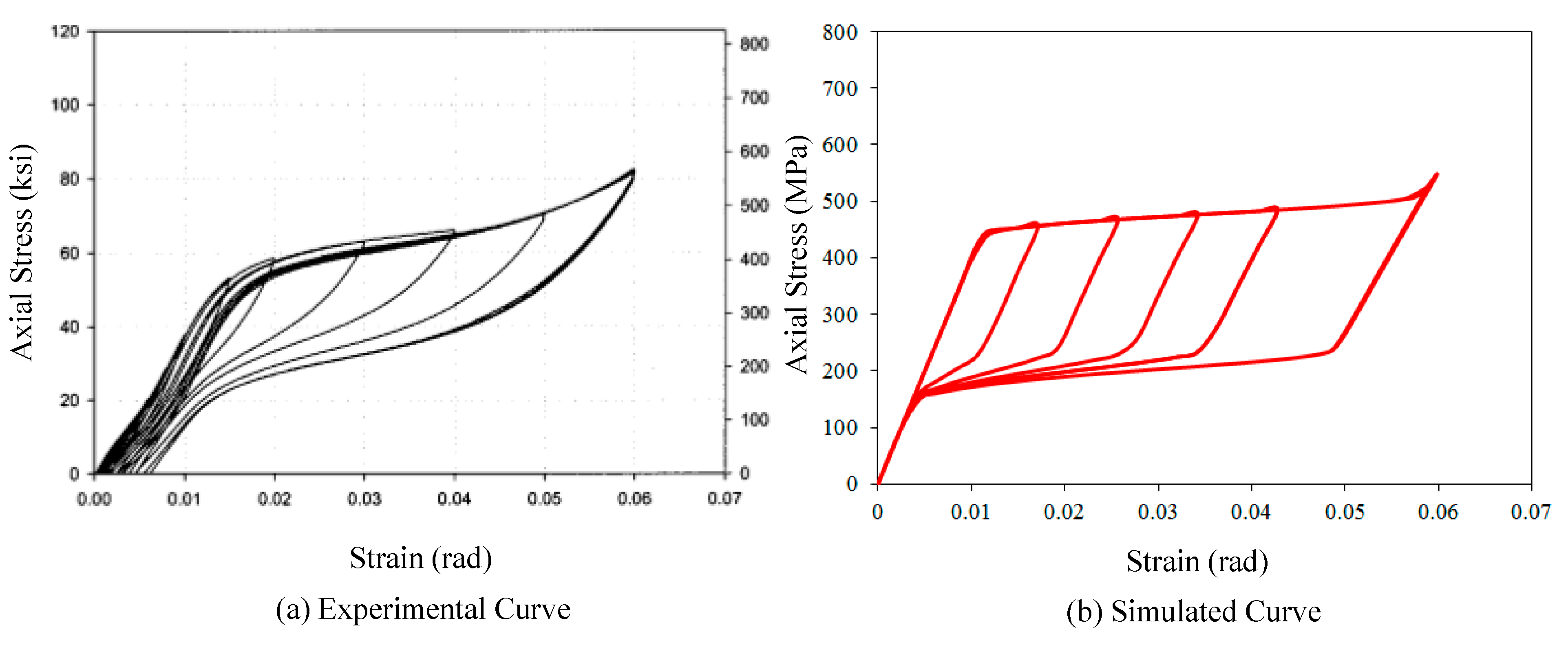
29]. This UMAT model completely reflects phase transformation superelasticity at a constant room temperature. The material properties required as input values to the UMAT subroutine model are acquired from the results of the uniaxial pull-out tests during loading, unloading, and reloading cycles under isothermal conditions. The UMAT subroutine can be implemented on the ABAQUS program associated with the FORTRAN computer language. The stress and strain curves for the superelastic SMA material are illustrated in
Figure 8. For this numerical simulation, the required material properties (
i.e., elastic modulus (40 GPa), Poisson’s ratio (0.33), martensite start stress (440 MPa), martensite finish stress (540 MPa), austenite start stress (250 MPa), austenite finish stress (140 MPa), and transformation strain (0.042), phase transformation temperature (22 °C)) were obtained from uniaxial pull-out tests performed by DesRoches
et al. [
23]. The simulated stress and strain curve was denoted by a series of straight lines whose paths coincide with each phase transformation. During the loading path, the simulated curve shows a good agreement with the experimental curve. The real superelastic SMA materials behave with different elastic properties between martensite and austenite. On the other hand, the UMAT model, produced based on Aurrichio’s subroutine code [
28], assumes that the unloading slope during elastic strain recovery is the same as the initial loading slope, in order to easily achieve linear interpolation between phase transformations. Algorithmically, phase transformation displayed at the subroutine proceeded with linearly variable martensite fractions (ranging from 0 to 1.0) in the time-discrete evolution equation. The UMAT model overestimates stiffness upon unloading (reverse phase transformation), and consequently the simulated curve is somewhat fatter when compared to the experimental curve.
Figure 7.
3D finite element (FE) analysis models for the recentering slit damper system, (a): Element Mesh; (b): Loading and BC’s.
Figure 7.
3D finite element (FE) analysis models for the recentering slit damper system, (a): Element Mesh; (b): Loading and BC’s.
The transition temperature range (TTR) for each superelastic (pseudoelastic) SMA depends on its composition, which causes considerable variability. The SMA specimens used for pull-out tests were composed of 56% nickel by weight and 44% titanium. This composition has 1% more nickel content as compared to nominal Nitinol (nickel-titanium) alloys (55% nickel by weight and 45% titanium), and thus these SMA specimens show low austenite start temperature (
As), which is −11 °C [
23]. The SMA specimens were heated at 450 °C (annealing temperature) for one hour before water quenching. In fact, the type of such superelastic SMA materials can be limitedly implemented in the warm area because austenite phase transformation without heating occurs at room temperature. For such reason, the behavior of the superelastic SMA was only taken into consideration for FE analyses regardless of austenite finishing temperature after completing austenite phase transformation.
Figure 8.
Simulated stress-strain curve for the super-elastic SMA material, (a): Experimental Curve; (b): Simulated Curve.
Figure 8.
Simulated stress-strain curve for the super-elastic SMA material, (a): Experimental Curve; (b): Simulated Curve.
6. Modeling Verifications
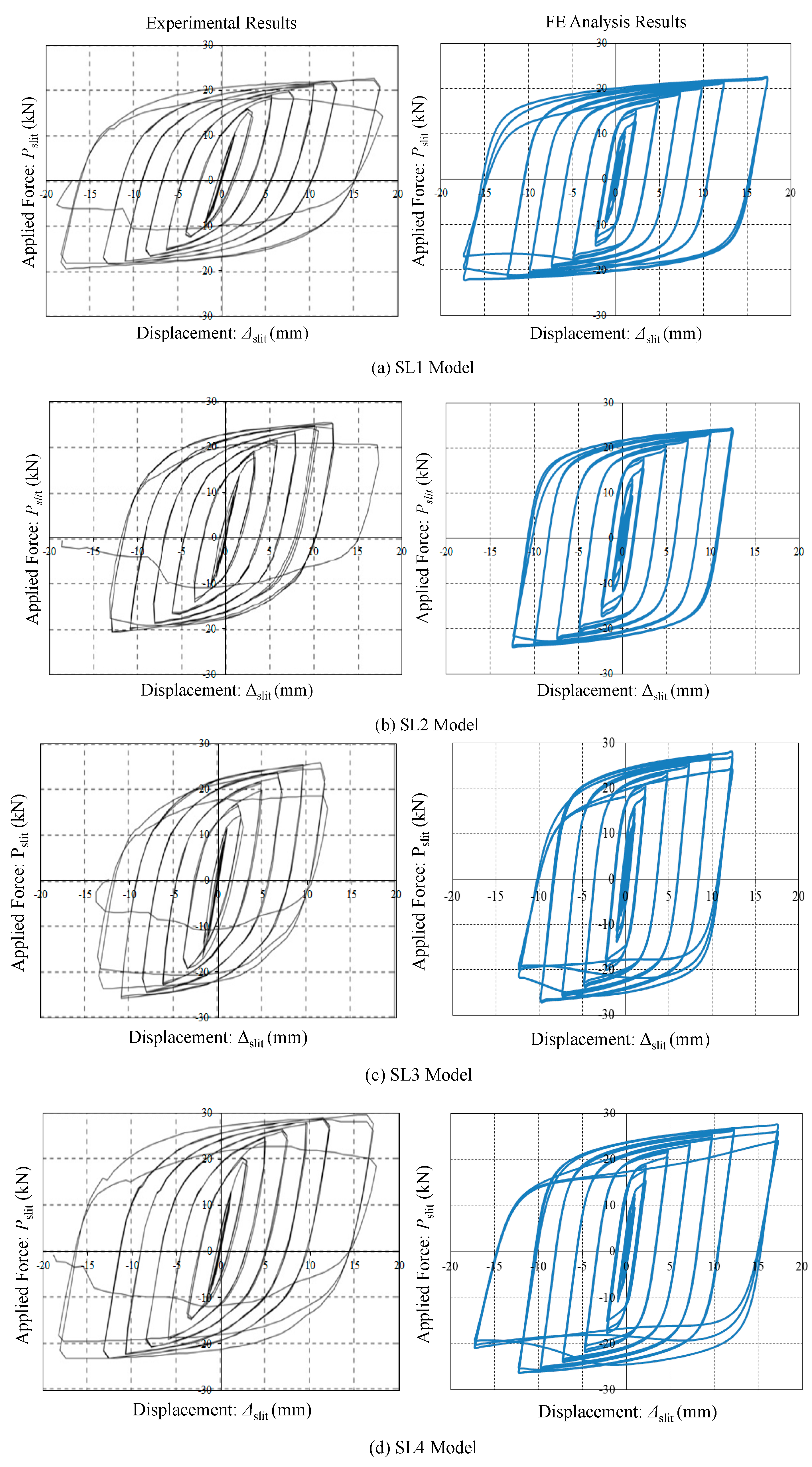
The FE analysis results are compared with the experimental test results for the purpose of verifying the adequacy of FE modeling. The results were obtained from the experimental tests performed on steel slit dampers without seismic restrainers, which were subjected to cyclic shear loads. The applied force
versus displacement curves for slit damper models (
Pslit vs. Δ
slit) is presented in
Figure 9. The instrumentation for applied force and displacement measurement is illustrated in
Figure 4. The experimental tests were conducted until slit damper specimens completely failed by fracture while the FE analyses were carried out with the same load history as the comparable experimental test.
All steel slit damper specimens are able to dissipate a considerable amount of yielding energy even under small displacement loading owing to the bending mechanism at the slender strips. Furthermore, the characteristics of the used base steel materials enable these damper systems to behave well with gradual strain hardening and Bauschinger behavior, as can be seen in
Figure 9. In spite of stable energy dissipation, the amount of permanent deformation augments as the number of loading cycles simultaneously increases. The ratio of strip depth to strip width (
b/
lo), which is a significant parameter used to classify the specimen, has an influence on ultimate strength at the resulting curve. The SL1 specimen, which has the smallest
b/
lo ratio, only reaches the ultimate strength of approximately 21.5 kN at the displacement of 17.5 mm, while the SL6 specimen designed with the largest
b/
lo ratio gets to as much as 32.5 kN strength at the displacement of 10 mm. Rapid strength degradation is observed at the behavior of the SL6 specimen due to the shortest strip depth after reaching ultimate strength. On the other hand, the SL1 specimen designed with relatively long strip depth (
lo = 97 mm) arrives at the ultimate displacement without strength degradation, meaning that this model possess excellent ductility. In general, both cyclic curves compared to each other show good agreements in terms of initial stiffness, yield force, post-yielding envelope, unloading stiffness, reloading stiffness, ultimate force, permanent deformation, and even pinching points. The FE models also exhibit symmetric-shape hysteresis loops with stable energy dissipation before strength degradation occurs. These good agreements between experimental results and analysis results indicate that FE models provided herein are appropriate for estimating the behavior of the slit dampers cyclically tested. The effect of the design parameter as well as that of the used base material can be examined through the FE analysis results, simultaneously.
Figure 9.
Applied forc0e vs. displacement curves for steel slit (SL) damper models, (a): SL1 Model; (b): SL2 Model; (c): SL3 Model; (d):SL4 Model; (e): SL5 Model and (f): SL6 Model.
Figure 9.
Applied forc0e vs. displacement curves for steel slit (SL) damper models, (a): SL1 Model; (b): SL2 Model; (c): SL3 Model; (d):SL4 Model; (e): SL5 Model and (f): SL6 Model.
For more detailed examination, comparisons of experimental results (Exp.) to FE analysis results (Anal.) are summarized in
Table 2. The resulting findings, such as initial stiffnesses (
Kslit), yield forces (
Pslit,y), ultimate forces (
Pslit,max), yield displacements (Δ
slit,y), and ultimate displacements (Δ
slit,max) for individual slit damper specimens are listed in this table. The initial stiffnesses are obtained from yield force divided by yield displacement as follows:
The initial stiffnesses can be theoretically defined with an assumption that individual strips are considered to be fully constrained beams at both end supports, and thus determined as follows:
where
n and
ES indicate the number of strips and the elastic modulus of Gr. 50 steel materials, respectively. A coefficient used as an index to judge the accuracy of measured stiffnesses (
Kslit) compared to theoretical computation can be defined as the following ratio:
The theoretically calculated yield forces for individual specimens can be determined based on the plastic bending mechanisms under perfectly elasto-plastic material behavior as follows:
where
MP stands for the full plastic moment when plastic hinges occur at both ends of each strip. Finally, the degree of ductility can be expressed as the ratio of yield displacement to ultimate displacement before failure.
Table 2.
Comparisons of experimental results to FE analysis results for steel slit damper models.
Table 2.
Comparisons of experimental results to FE analysis results for steel slit damper models.
| Model | Kslit (kN/mm) | c | Pslit,y (kN) | Pslit,max (kN) | Δslit,y (mm) | Δslit,max (mm) | μ |
|---|
| ID | Exp. | Anal. | Exp. | Anal. | Theo. | Exp. | Anal. | Exp. | Anal. | Exp. | Anal. | Exp. | Anal. | Exp. |
|---|
| SL1 | 23.49 | 23.77 | 0.98 | 0.99 | 11.59 | 11.51 | 11.41 | 22.61 | 22.30 | 0.49 | 0.48 | 17.32 | 17.50 | 35.42 |
| SL2 | 33.56 | 34.00 | 1.00 | 1.01 | 13.08 | 13.09 | 12.92 | 25.54 | 24.21 | 0.39 | 0.38 | 12.05 | 12.50 | 30.86 |
| SL3 | 50.07 | 52.48 | 1.01 | 1.06 | 15.00 | 15.02 | 15.22 | 25.81 | 27.92 | 0.30 | 0.29 | 11.66 | 12.50 | 38.49 |
| SL4 | 32.49 | 32.49 | 1.00 | 1.00 | 14.58 | 14.62 | 14.62 | 29.61 | 27.82 | 0.45 | 0.45 | 16.47 | 17.50 | 36.69 |
| SL5 | 44.75 | 44.08 | 0.99 | 0.97 | 16.19 | 16.11 | 16.31 | 31.26 | 28.82 | 0.36 | 0.37 | 11.92 | 12.50 | 32.83 |
| SL6 | 60.24 | 60.52 | 1.00 | 1.01 | 17.45 | 17.47 | 17.55 | 35.68 | 31.89 | 0.29 | 0.29 | 11.44 | 10.00 | 39.19 |
As can be seen in the table, initial stiffnesses obtained from experimental tests show good agreements with those from FE analyses. Furthermore, stiffness ratios calculated by Equation (3) are fairly close to the value of 1.0. In addition to the initial stiffness, the values of forces and displacement also show good matches between experimental results and FE analysis results.
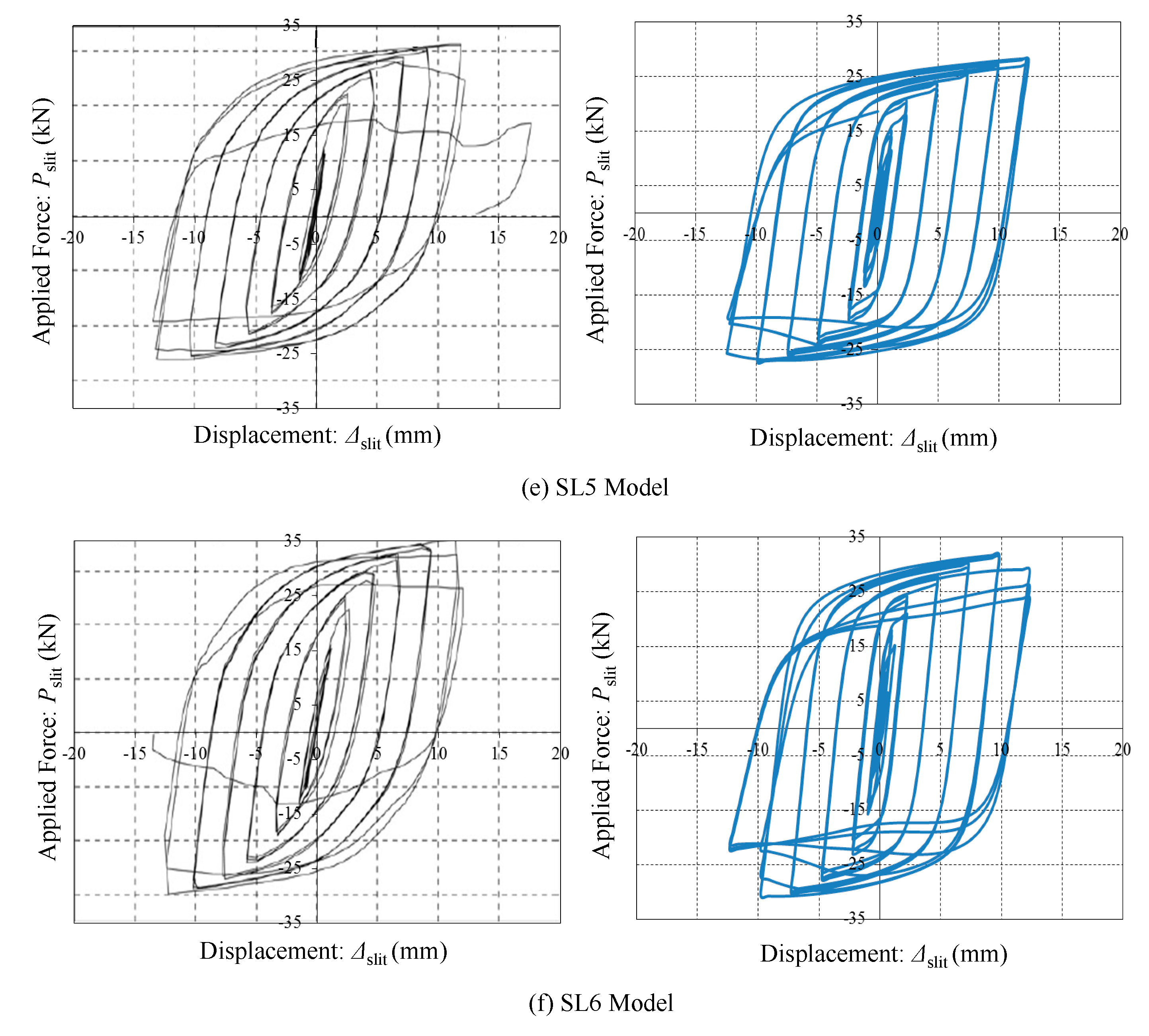
The cyclic curves simulated by the FE models for superelastic SMA bars subjected to bending moment are investigated so as to validate the adequacy of the proposed UMAT model.
Figure 10 shows applied force
versus displacement curves for a single fixed-end supported SMA bar under transverse end shear force. Including the steel slit dampers (see
Figure 9), equivalent damping ratios (ξ
eq) for superelastic SMA bars used herein, which were calculated based on the work of Jacobsen [
30], are also presented in this figure. The major limitations for the application of Jacobsen are the assumption of a steady state response (sinusoidal) and the arbitrary choice of the one cycle criterion where Jacobsen uses only one cycle of the hysteresis loop to assess the equivalent viscous damping. Jacobsen’s approach sometimes overestimates the value of the damping for some hysteresis loops. The damping capacity of the assembled system will be improved by adding more equivalent damping ratios provided by superelastic SMA bars. These cyclic curves perfectly follow SMA’s material behavior. In spite of undergoing considerable plastic deformation, superelastic SMA bars completely recover their original configurations upon unloading. They display symmetric behavior curves in tension and compression. The recentering forces that arise during reverse phase transformation serve to reduce permanent deformation mostly occurring at the steel slit damper. It is additionally confirmed that the elastic response before yielding can meet the fixed-end beam deflection theorem (e.g.,
P =
KΔ = 12EIΔ/L
3). After applying this theorem, the initial stiffness of the presented SMA bending bar (
KSMA) is taken as the value of 5.62 kN/mm. The yield force (
PSMA,y) can be thereafter estimated to be 28.26 kN at the yield state (∆
SMA,y = 5 mm). These calculated values coincide with schematic representations plotted as the dashed lines in
Figure 10. When synthesizing these observation results, the 3D FE models presented herein are adequate to simulate the behavior of recentering slit dampers during quasi-static (or cyclic) loading analyses.
Figure 10.
Applied force vs. displacement curves for fixed-end supported SMA bars under transverse end shear force, (a): ΔSMA,max = 17.5mm Case; (b): ΔSMA,max = 12.5mm Case.
Figure 10.
Applied force vs. displacement curves for fixed-end supported SMA bars under transverse end shear force, (a): ΔSMA,max = 17.5mm Case; (b): ΔSMA,max = 12.5mm Case.
7. Analysis Results and Observations
The 3D FE models for several recentering slit damper models (
Figure 7) were loaded according to quasi-static displacement load history (
Figure 13a) in order to simulate their inelastic behavior. After FE analyses, parametric studies are conducted to explore the size of steel slit dampers and the effect of superelastic SMA bars in the integrated system. The applied force
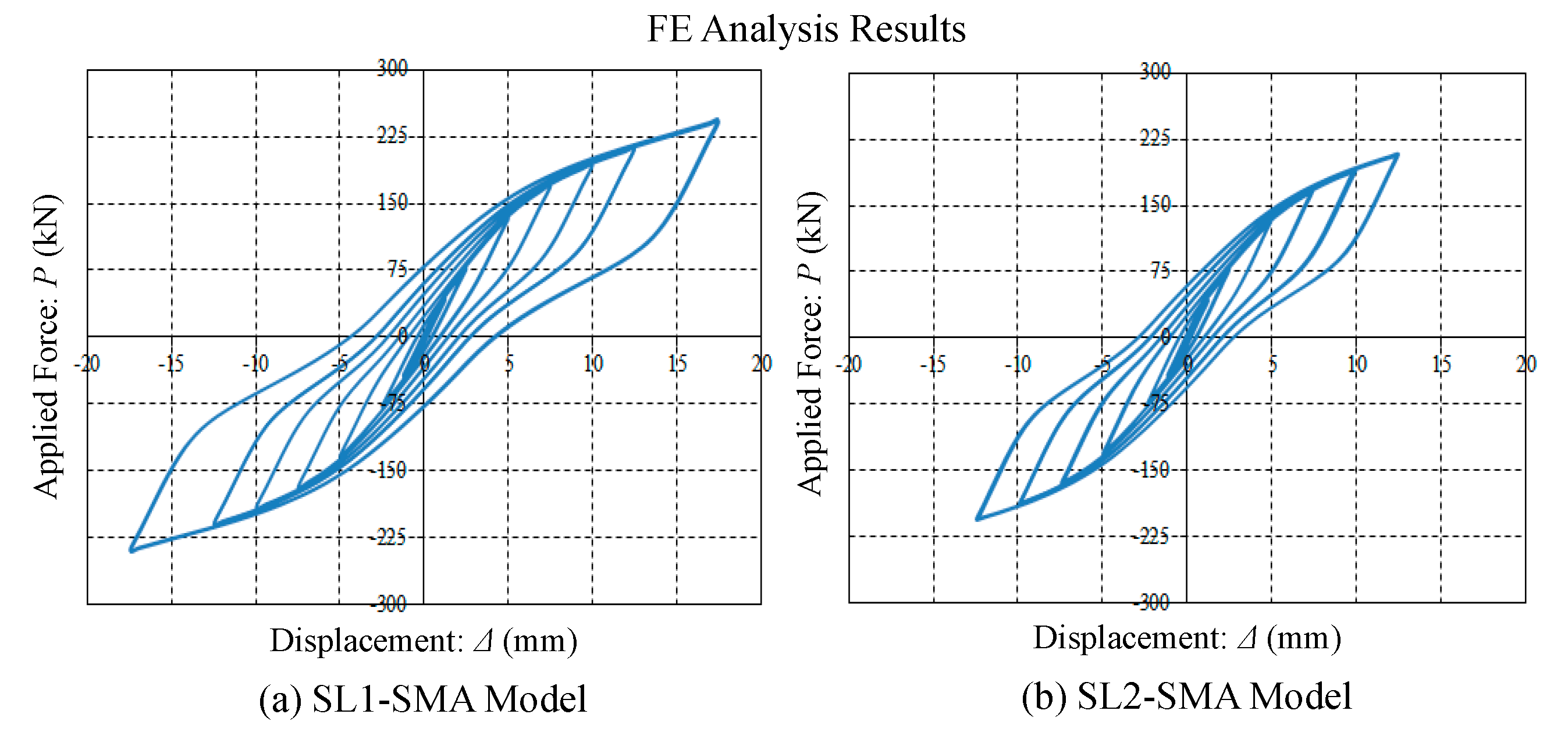
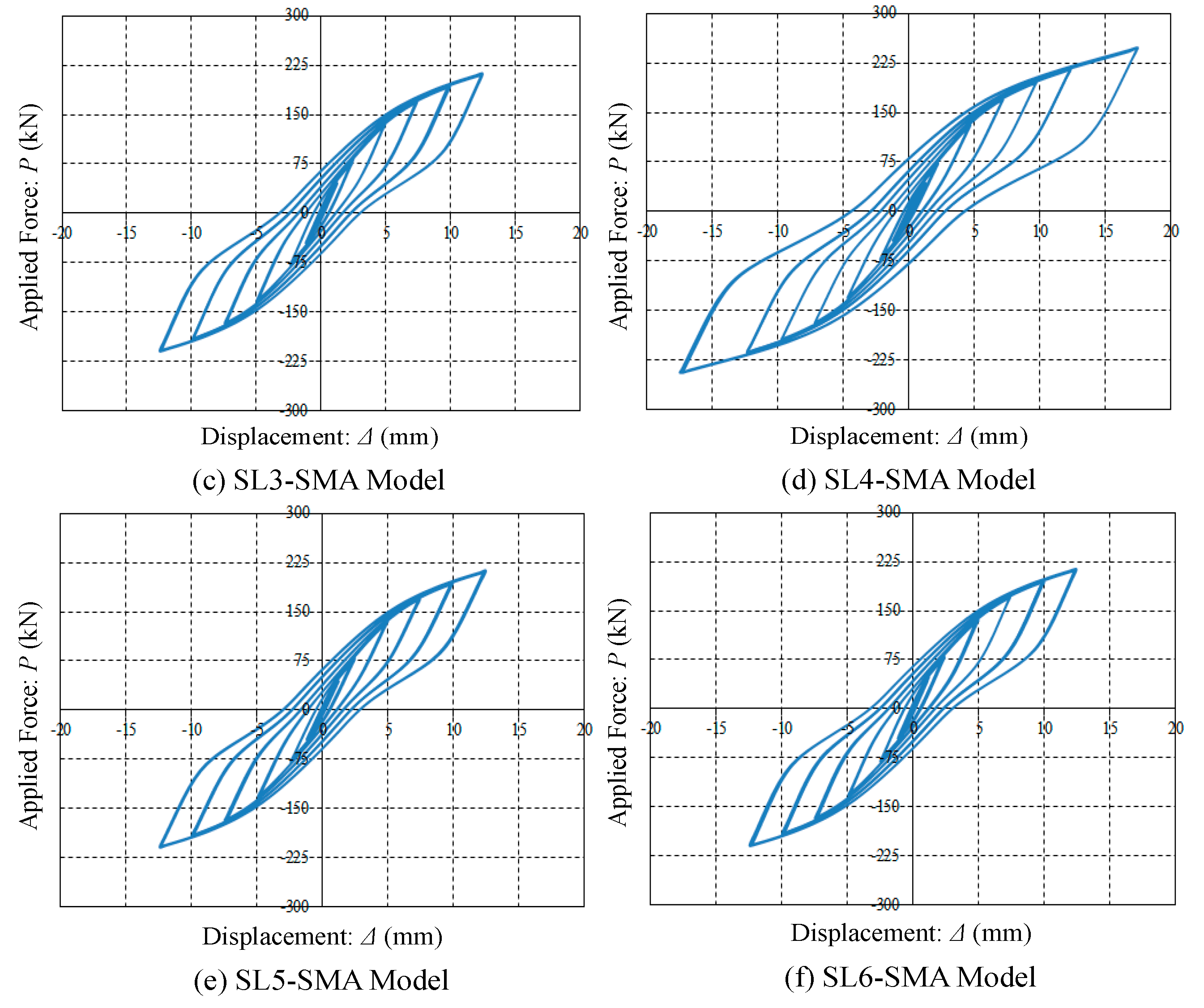
versus displacement hysteresis curves for six recentering slit damper models (SL1-SMA to SL6-SMA models) are presented in
Figure 11. It can be shown that the recentering slit dampers proposed possess comparative advantages regarding ultimate strength and recentering capacity over the conventional steel slit dampers. Strength capacities are remarkably improved up to more than ten times. In particular, the superelastic SMA bending bars functioning as reinforcing restrainers avoid triggering strength degradation at the hysteretic curves, within the range of displacement loading. Most of all, these bars supplementally acting as recentering devices help to decrease permanent deformation to on average a 27% level of the conventional slit damper system. For instance, the SL1 model has approximately 15 mm permanent deformation at the last loading cycle (
Figure 9) while the SL1-SMA model has only about 4 mm of permanent deformation.
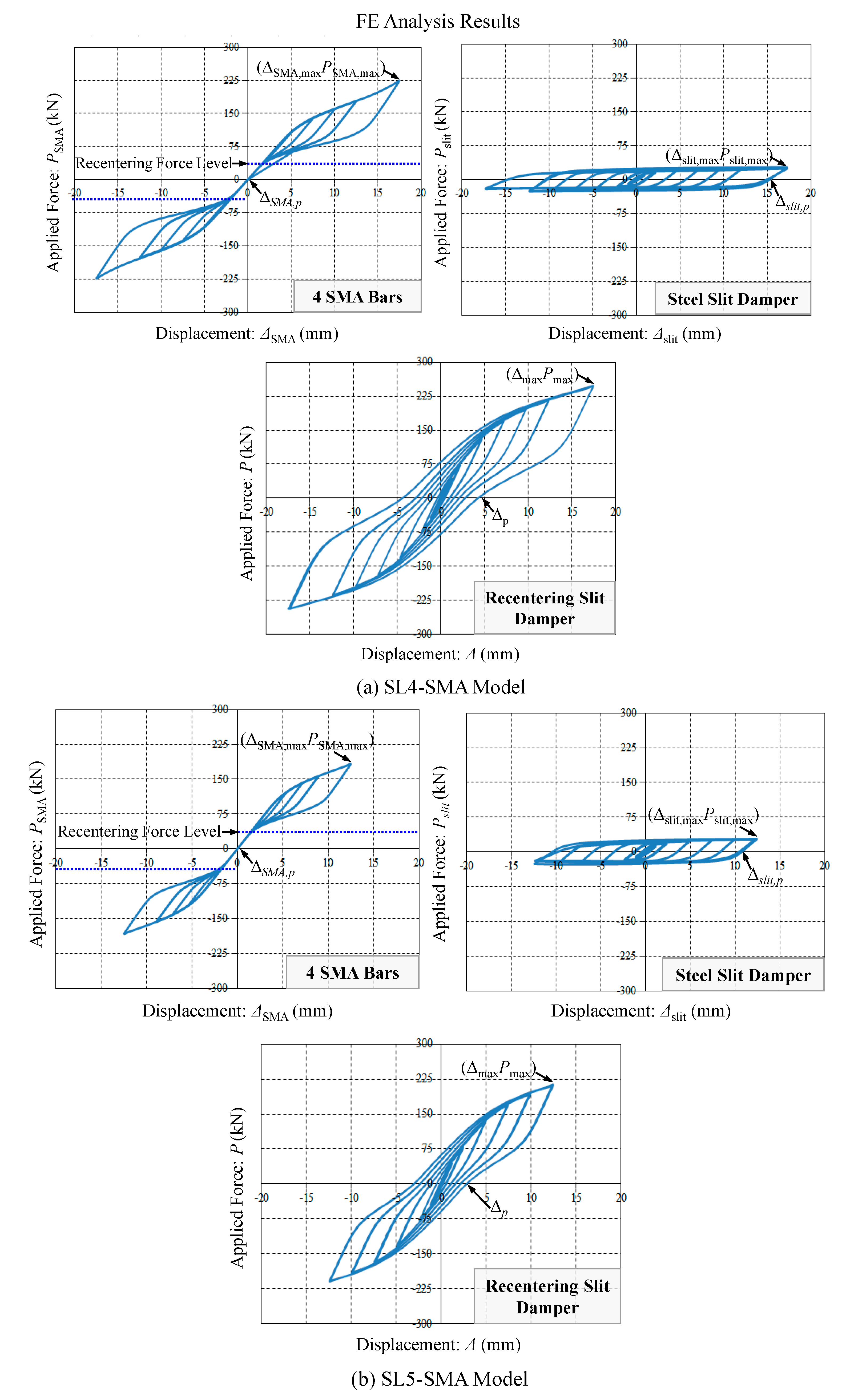
The response mechanism for the recentering slit damper can be constituted by deformable contributions obtained from four SMA bars and one steel slit damper (
Figure 4). The simulated curves for the behavior of each component are presented in
Figure 12, including the total behavior of the recentering slit damper. The lower limit for the level of recentering force is plotted as the dashed line in the figure. The quantities for specific points defined in this figure (
i.e.,
PSMA,max, Δ
SMA,max Δ
SMA,p, and six other points) are summarized in
Table 3. In order to verify that individual components (
i.e., four SMA bars and steel slit damper) shall be assembled in parallel to directly formulate the behavior of the recentering slit damper system, the ratio of force discrepancy between component assemblage and integrated system is presented in this table as follows:
The ratios of maximum forces and permanent displacements (
Pmax,ratio and
Δp,ratio) are also investigated to elucidate that the recentering slit dampers proposed herein are improved with respect to ultimate strength and permanent deformation in comparison with the conventional steel slit dampers.
The maximum recoverable displacements computed by subtracting permanent deformation from maximum displacement at the last loading cycle, such that
Δmax –
Δp, are necessary to assess recentering capability according to design parameters. The recentering ratios (RRs) that result in the index to evaluate the self-centering capacity of individual recentering slit dampers are determined from maximum recoverable displacements normalized by corresponding maximum displacements as follows:
Table 3.
Summary of FE analysis results.
Table 3.
Summary of FE analysis results.
| Model ID | 4 SMA Bars | Steel Slit Damper | Recentering Slit Damper System |
|---|
| PSMA,max | ΔSMA,max | ΔSMA,p | Pslit,max | Δslit,max | Δslit,p | Δmax | Δp | Pmax | PSMA,max + Pslit,max | Perror (%) | Pmax,ratio | Δp,ratio | RR (%) |
|---|
| SL1-SMA | 223.2 | 17.5 | 0 | 22.2 | 17.5 | 15.1 | 17.5 | 3.8 | 243.0 | 245.4 | 0.99 | 10.95 | 0.25 | 78.29 |
| SL2-SMA | 182.8 | 12.5 | 0 | 23.9 | 12.5 | 10.6 | 12.5 | 2.5 | 208.0 | 206.7 | 0.62 | 8.70 | 0.24 | 80.00 |
| SL3-SMA | 182.8 | 12.5 | 0 | 27.8 | 12.5 | 10.8 | 12.5 | 2.8 | 212.0 | 210.6 | 0.66 | 7.63 | 0.26 | 77.60 |
| SL4-SMA | 223.2 | 17.5 | 0 | 27.5 | 17.5 | 15.2 | 17.5 | 4.2 | 248.0 | 250.7 | 1.09 | 9.02 | 0.28 | 76.00 |
| SL5-SMA | 182.8 | 12.5 | 0 | 28.2 | 12.5 | 10.7 | 12.5 | 2.9 | 213.0 | 211.0 | 0.94 | 7.55 | 0.27 | 76.80 |
| SL6-SMA | 182.8 | 12.5 | 0 | 29.0 | 12.5 | 10.2 | 12.5 | 3.0 | 214.0 | 211.8 | 1.03 | 7.38 | 0.29 | 76.00 |
Figure 11.
Applied force vs. displacement curves for recentering slit damper models, (a): SL1 SMA Model; (b): SL2 SMA Model; (c): SL3 SMA Model; (d): SL4 SMA Model; (e): SL5 SMA Model and (f): SL6 SMA Model.
Figure 11.
Applied force vs. displacement curves for recentering slit damper models, (a): SL1 SMA Model; (b): SL2 SMA Model; (c): SL3 SMA Model; (d): SL4 SMA Model; (e): SL5 SMA Model and (f): SL6 SMA Model.
The superelastic SMA bending bars themselves completely recover from plastic deformation in that they have zero permanent deformation upon unloading (ΔSMA,p = 0 mm). The slit damper can only recover elastic deformation to the contrary, and thus exhibits a considerable amount of permanent deformation upon unloading as is presented in the table. Once the recentering force attributed to the contribution of superelastic SMA bending bars exceeds the maximum force of the slit damper, permanent displacement starts to decrease in the integrated system. The values of Perror are less than 1.0% at most, implying that the total behavior of the recentering slit damper can be equivalently formulated by combining the responses of two components in parallel. The recentering slit dampers have on average 8.5 times larger maximum forces than the conventional steel slit dampers within the range of displacement loading, but their permanent deformations decrease by about 74%, indicating on average Δp,ratio = 0.26. The recentering ratios (RRs) exceed 76% for all model cases. It can be thus concluded that the superelastic SMA bending bars lead the proposed damper systems in the betterment of structural performance in terms of strength and recentering capacity.
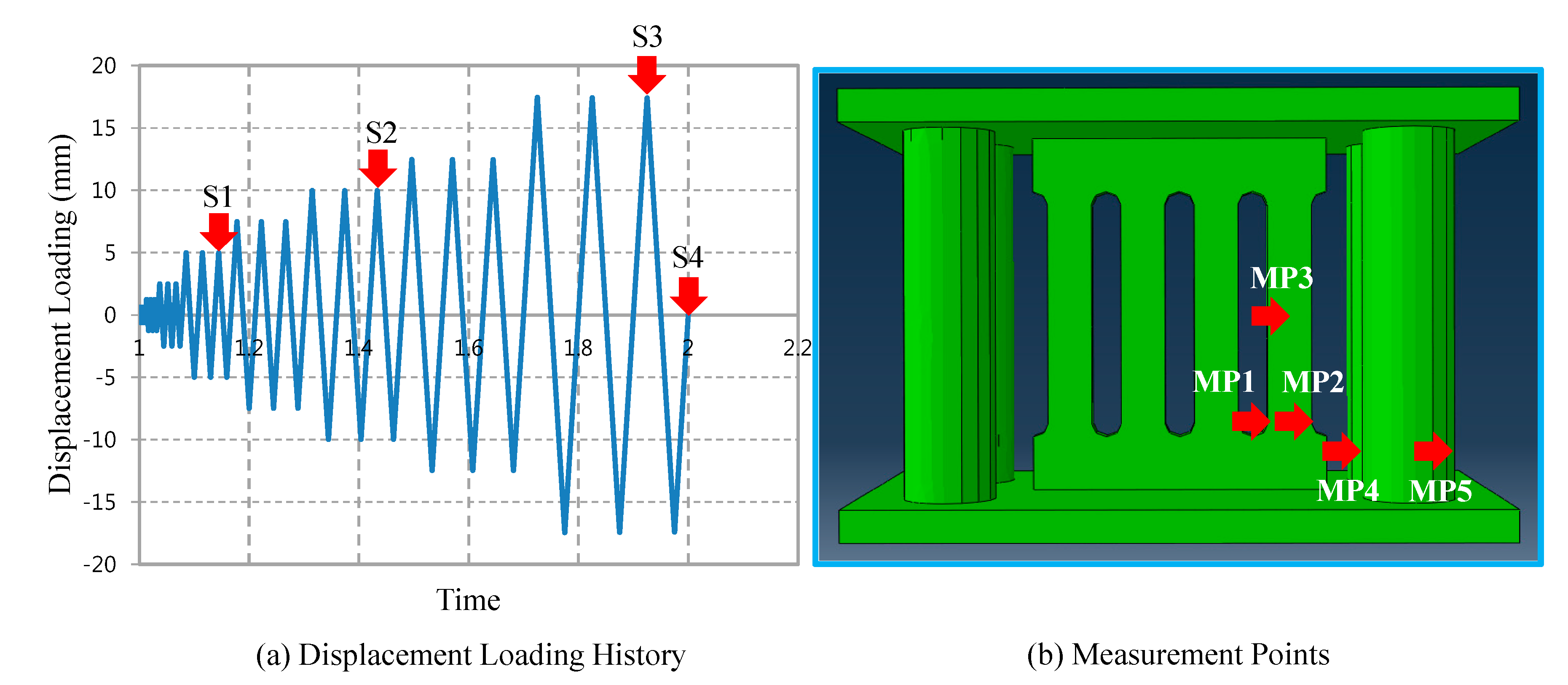
For more observation of FE analysis results, both filed contours and history outputs are detected at the specific loading steps. The target loading steps for observing field contours and the measurement points for monitoring stress-strain history output curves are illustrated in
Figure 13(a,b), respectively. Four target loading steps (
i.e., S1 = 5 mm, S2 = 10 mm, S3 = 17.5 mm, and S4 = 0 mm) are selected during FE analyses. Five monitoring set points used to independently measure uniaxial stress-strain history outputs (
i.e., MP1 to MP5) are assigned to the FE models, as plotted in
Figure 13b. Except for the MP3 point assigned to the middle of the strip, the other four points can detect plastic hinges caused by bending moment at the end of the support. The bending mechanism can be verified by the stress-stain curves measured from these set points.
Figure 12.
Simulated curves for the behavior of individual components (4 SMA bars and steel slit damper) and the total behavior of the recentering slit damper systems, (a): SL4-Model and (b): SL-5 Model.
Figure 12.
Simulated curves for the behavior of individual components (4 SMA bars and steel slit damper) and the total behavior of the recentering slit damper systems, (a): SL4-Model and (b): SL-5 Model.
Figure 13.
Target loading steps for field contour observation, (a): Displacement Loading History and (b): Measurement Points.
Figure 13.
Target loading steps for field contour observation, (a): Displacement Loading History and (b): Measurement Points.
According to individual displacement loading steps, the field contours for axial stress (S11) and axial strain (L11) components distributed over the recentering slit damper (SL4-SMA model) are presented in
Figure 14 and
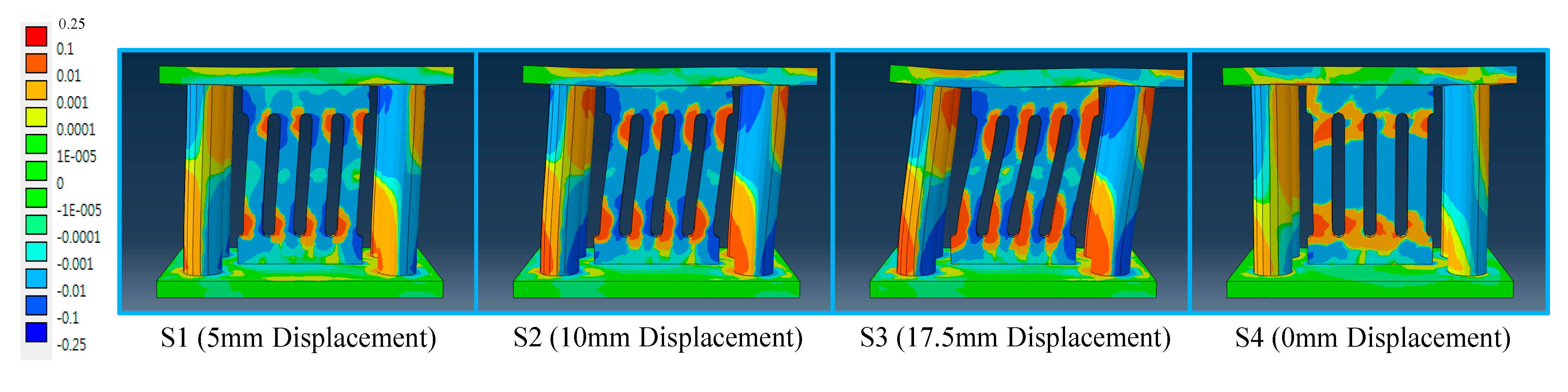
Figure 15, respectively. The magnitudes of the field contours are displayed with the legend of the colored bar graph. The orange-colored (under tension stress) and blue-colored (under compression stress) contours, which are intensively distributed at the end of strips and SMA bending bars, indicate the onset of plastic yielding. The symmetric distribution between tension and compression has an influence on the bending mechanism. As the displacement load applied to the recentering slit damper increases, plastic stress contours spread toward the middle of strips and SMA bending bars. The recentering slit dampers subjected to 17.5 mm displacement loads experience almost ultimate condition. Although the last loading step (S4) reinstates the SL4-SMA model from the previous ultimate load, residual stresses even exceeding the yield level are intensively distributed over both ends of the strips. In contrast, the SMA bending bars are not susceptible to yield stress, and recover their original shape with almost zero residual stress at the last loading step. These SMA bending bars preserve the recentering slit damper from out-of-plane deformation generally arising due to instability. It can be concluded that the superelastic SMA bending bars play a prominent role to stabilize the damper system as well as to decrease permanent deformation. The axial strain field contours exhibit the same plasticity pattern as the corresponding axial stress field contours under the identical loading step (
Figure 15).
Figure 14.
Axial stress components (S11) distributed over the slip plate damper (SL4-SMA model) according to individual loading steps (Unit: MPa).
Figure 14.
Axial stress components (S11) distributed over the slip plate damper (SL4-SMA model) according to individual loading steps (Unit: MPa).
Figure 15.
Axial strain components (LE11) distributed over the slip plate damper (SL4-SMA model) according to individual loading steps (Unit: rad).
Figure 15.
Axial strain components (LE11) distributed over the slip plate damper (SL4-SMA model) according to individual loading steps (Unit: rad).
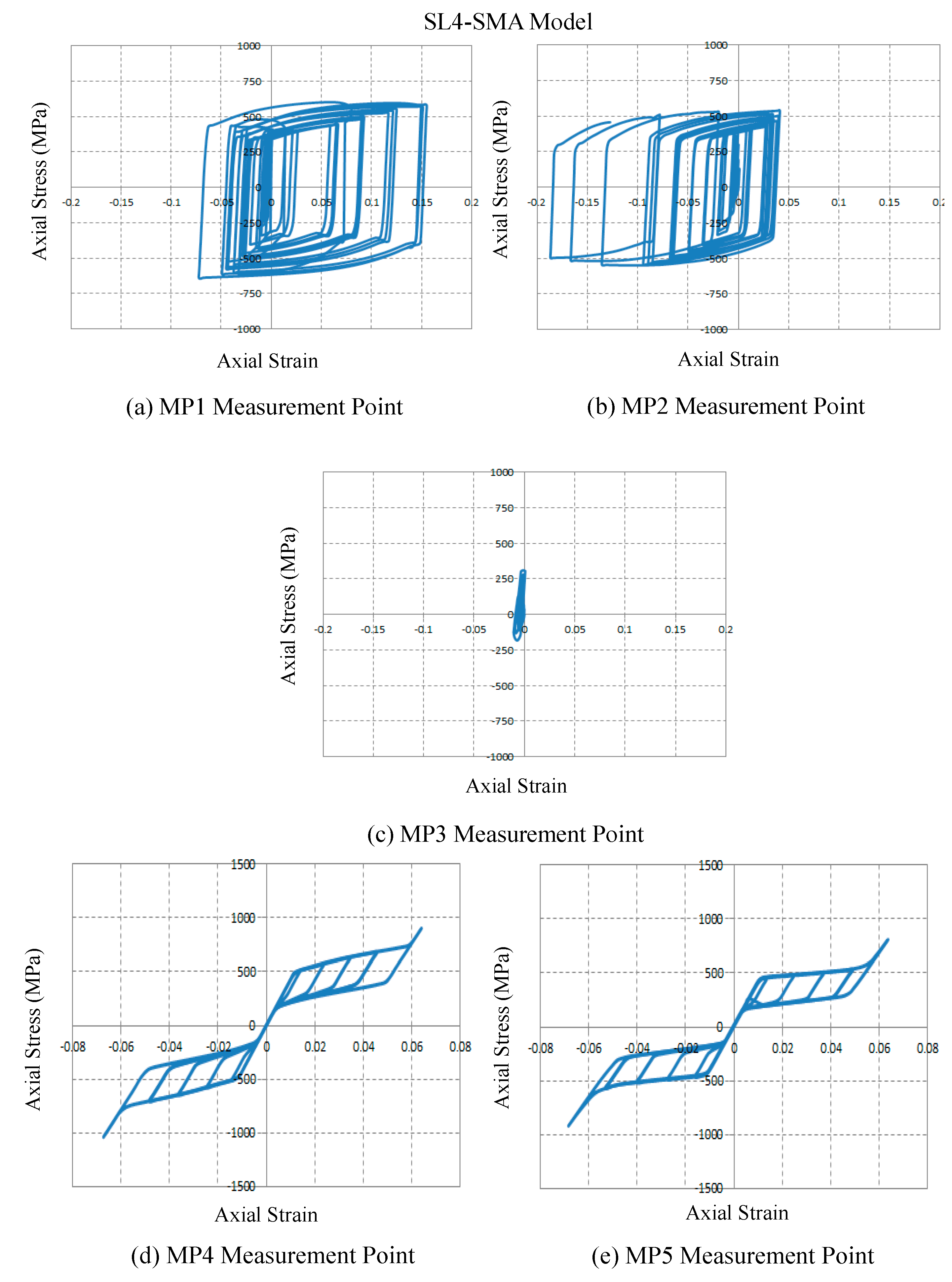
Figure 16.
True stress and strain curves at the measurement points, (a): MP1 Measurement Point; (b): MP2 Measurement Point; (c): MP3 Measurement Point; (d): MP4 Measurement Point and (e): MP5Measurement Point.
Figure 16.
True stress and strain curves at the measurement points, (a): MP1 Measurement Point; (b): MP2 Measurement Point; (c): MP3 Measurement Point; (d): MP4 Measurement Point and (e): MP5Measurement Point.
The stress and strain curves obtained from the measurement points are shown in
Figure 16. The resulting curves measured at the end of the strip (e.g., MP1 and MP2 points) exceed the limit of plastic yielding (316.5 MPa). Furthermore, nonlinear isotropic and kinematic hardening behavior affected by base material’s properties may be observed during cyclic loading. On the contrary, the middle of the strip where relatively less bending moment occurs (MP3 point) keeps the elastic condition during all cyclic loading. For the superelastic SMA bending bars, both stress and strain curves measured from MP4 and MP5 points are the flag-shaped hysteresis loops identical to their unique material behavior. It can be thus concluded that the implemented UMAT subroutine used for simulating the behavior of superelastic SMA material is able to accurately evaluate mechanical stress and structural behavior.


