1. Introduction
With the continuous advancement of automation and intelligent technologies, mobile robots have been widely deployed in intelligent manufacturing, warehousing and logistics, engineering inspection, and service robotics [
1,
2,
3]. In complex environments, mobile robots are required not only to safely reach the target from the start point, but also to maintain smooth trajectories, continuous control inputs, and rapid adaptability to environmental changes during motion. Therefore, generating a high-quality reference trajectory that satisfies environmental constraints while remaining stably executable by the lower-level controller has become a key issue in autonomous navigation systems for mobile robots [
4,
5,
6].
In modern autonomous navigation frameworks, path planning and trajectory tracking are generally treated as two closely related yet functionally independent modules. Path planning is mainly responsible for generating a collision-free path from the start point to the goal according to the environmental map, whereas trajectory tracking control drives the robot to move stably along the reference path. Existing path planning studies have mainly focused on geometric reachability, obstacle avoidance safety, and path length optimization. Typical graph-search methods, such as A* and its variants, can efficiently generate globally feasible paths in known environments with high search efficiency and strong determinism [
7,
8,
9]. Sampling-based methods, such as RRT and RRT*, show strong adaptability in complex spaces and high-dimensional planning problems [
10,
11,
12,
13,
14]. Meanwhile, local planning methods represented by the Dynamic Window Approach (DWA) and Timed Elastic Band (TEB) have also been widely applied to dynamic obstacle avoidance and local trajectory optimization [
10,
15,
16,
17,
18,
19,
20]. These methods have achieved substantial progress in improving path reachability and obstacle avoidance capability, thus providing an important foundation for autonomous navigation.
However, most existing studies emphasize the generation of a geometrically feasible path, while insufficient attention has been paid to whether such a path can be smoothly tracked and stably executed by the lower-level controller. First, the outputs of traditional path planning methods usually consist of discrete path points or polyline segments. In essence, they remain geometric path descriptions and generally lack systematic consideration of local curvature continuity, velocity allocation, and control input constraints [
13,
21,
22]. Second, for systems such as differential-drive mobile robots, which are subject to nonholonomic kinematic constraints and physical limits such as maximum linear velocity and maximum angular velocity, directly tracking an original polyline path often results in abrupt control input variations, actuator saturation, and amplified tracking errors in local corners or high-curvature regions [
4,
5,
8,
12]. Moreover, even when geometric continuity is improved through curve fitting or smoothing, the resulting path may still be difficult for the controller to execute stably if the matching relationship between local path curvature and robot motion capability is not explicitly considered [
12,
22,
23]. Therefore, generating a continuous path solely from a geometric perspective is insufficient for trajectory tracking control. Instead, a reference trajectory that simultaneously accounts for smoothness, trackability, and physical executability must be constructed.
To improve the compatibility of planned paths with lower-level controllers, increasing attention has been devoted to path smoothing, trajectory generation, and planning–control integration. Among these efforts, B-splines, Bézier curves, and clothoid curves have been widely employed for path continuity enhancement and curvature-constrained processing to alleviate the abrupt changes caused by original polyline paths [
13,
21,
22,
23,
24]. Some studies have further incorporated nonholonomic kinematic constraints, maximum curvature constraints, and velocity planning into the trajectory generation stage to enhance physical executability [
8,
12,
14]. In parallel, local replanning and trajectory stitching in dynamic environments have also attracted growing interest. Related studies based on the Timed Elastic Band framework represent local obstacle-avoidance trajectories as time-parameterized optimizable trajectories and seek a comprehensive trade-off among collision avoidance, trajectory smoothness, and motion feasibility. On this basis, subsequent improvements further incorporate the velocity information of dynamic obstacles into the local planning process, thereby enhancing obstacle avoidance efficiency and trajectory adaptability in dynamic environments [
9,
17,
18,
19,
20,
25].
From a comparative perspective, graph-search-based methods mainly emphasize global feasibility and path-length optimality, but their outputs are usually discrete and often require additional processing before they can be directly used for trajectory tracking. Smoothing- and curvature-aware trajectory generation methods improve geometric continuity and motion executability, but their computational burden and real-time applicability depend on the specific formulation. Local replanning and optimization-based methods are more adaptive in dynamic environments, yet they may still face a trade-off among smoothness, computational efficiency, and online implementation. Different from methods that mainly focus on geometric feasibility or local optimization alone, the present work places emphasis on generating a tracking-oriented reference trajectory with improved smoothness, kinematic executability, and local updating capability under a computationally practical framework.
In addition to path planning, trajectory smoothing, and local replanning, practical mobile robot systems also depend on reliable motion-related sensing and localization/state-estimation modules. For example, Cosenza et al. developed a virtual sensor for wheel angular speed estimation in a differential-drive wheeled robot, which improves motion-state perception and execution reliability [
26]. Pak and Ahn provided a recent survey of localization-oriented state-estimation algorithms, highlighting their fundamental role in autonomous navigation systems [
27]. Although these studies are not directly aimed at tracking-oriented reference trajectory generation, they provide important system-level support for the practical deployment and stable operation of mobile robots. Nevertheless, they do not explicitly address how to transform a geometrically feasible path into a smooth, kinematically executable, and dynamically updatable reference trajectory for lower-level tracking control.
Nevertheless, despite the above progress, existing methods still exhibit two major limitations. On the one hand, some methods emphasize geometric smoothing while insufficiently considering the compatibility between the generated trajectory and the tracking requirements of the lower-level controller. On the other hand, in dynamic environments, locally updated trajectories often lack a unified smooth stitching mechanism with the original global path, which may easily cause abrupt path switching and control input fluctuations. As a result, the practical gap between a geometrically feasible path and a controller-executable reference trajectory remains insufficiently addressed.
To address the above issues, this study proposes a reference trajectory generation method for mobile robots oriented toward trajectory tracking. The proposed method constructs a geometrically continuous path through initial path search, key-point sparsification, and cubic B-spline smoothing, and further adaptively corrects the reference velocity by considering the kinematic constraints of the differential-drive mobile robot and the local curvature characteristics of the path, thereby improving trajectory executability and motion smoothness. To handle local path invalidation in dynamic environments, a local replanning and trajectory stitching strategy is further introduced to enhance the adaptability of the reference trajectory to environmental changes. Compared with conventional methods, the proposed method integrates curvature continuity, kinematic constraints, velocity executability, and local dynamic updating into the planning layer, thereby improving the compatibility between the reference trajectory and the lower-level controller and reducing the tracking burden under complex operating conditions.
The main contributions of this study are summarized as follows:
A reference trajectory generation framework oriented toward trajectory tracking control is proposed for mobile robots, which unifies initial path search, key-point sparsification, smooth trajectory modeling, trackability analysis, and dynamic updating into a single pipeline, thereby enabling the transformation from a geometrically feasible path to a control-executable reference trajectory.
An adaptive reference velocity correction method is developed for differential-drive mobile robots in high-curvature path segments by incorporating a local trackability index and curvature constraints.
A local replanning and trajectory stitching mechanism is designed for dynamic environments to achieve smooth switching and stable execution of locally updated trajectories.
2. Kinematic Constraints of the Differential-Drive Mobile Robot
This study considers a two-wheeled differential-drive mobile robot as the research platform. For ease of analysis, the following assumptions are made: the robot body is treated as a rigid body, and the distance between the left and right driving wheels is assumed to remain constant; the wheels are subject to pure rolling constraints during motion, while lateral slip and skidding are neglected; in addition, the effects of air resistance, collisions, and other complex external disturbances are ignored. Based on these assumptions, the planar kinematic model of the differential-drive mobile robot can be established.
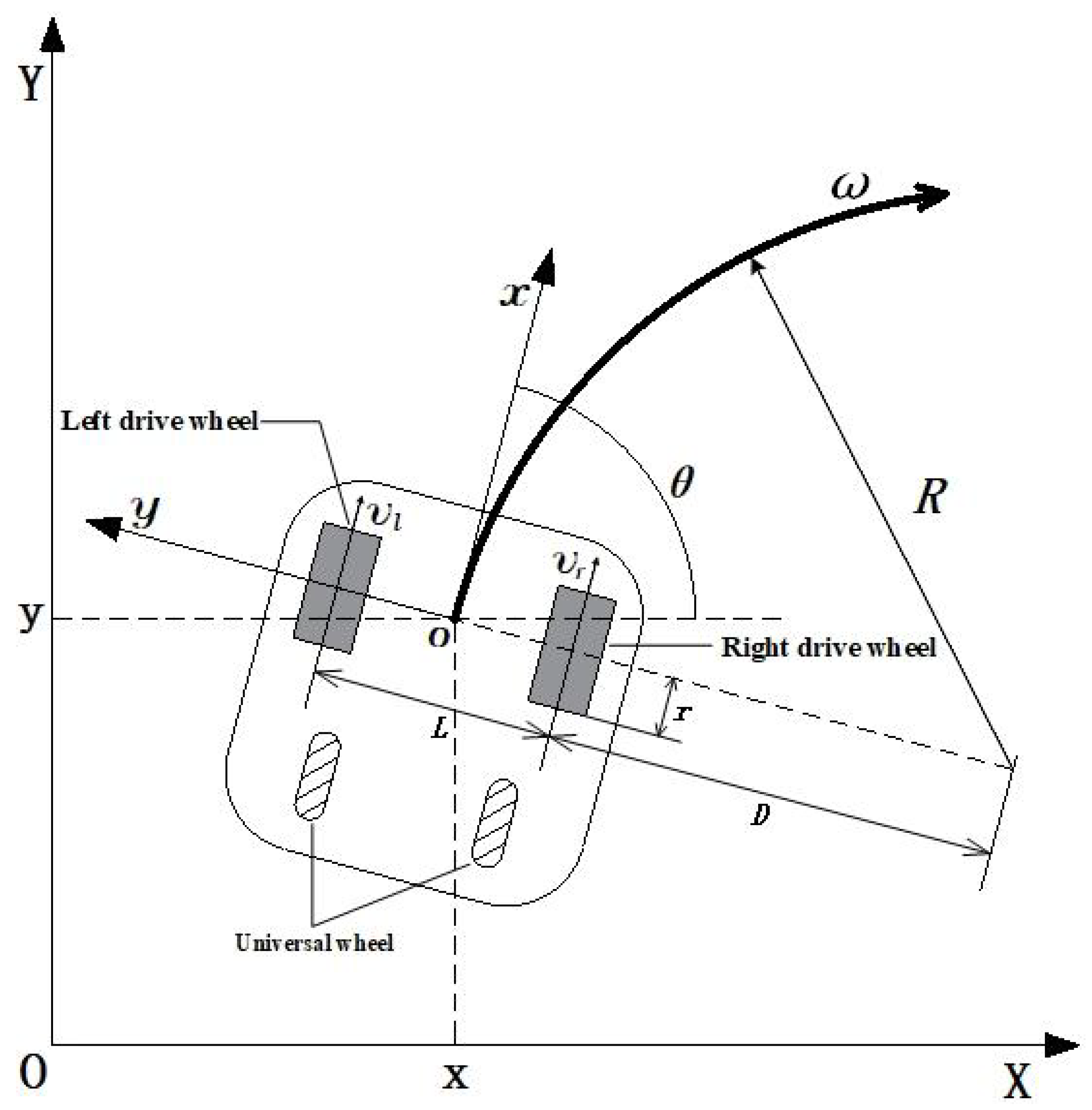
As shown in
Figure 1, a global coordinate frame
and a robot body-fixed coordinate frame
are established. Here,
denotes the position of the robot centroid in the global coordinate frame, and
denotes the robot heading angle.
v and
represent the linear velocity and angular velocity of the robot centroid, respectively. The angular velocities of the left and right driving wheels are denoted by
and
, respectively, while
r denotes the wheel radius and
L denotes the wheelbase. The pose of the mobile robot in the global coordinate frame can be expressed as
, and its motion state can be written as
. Under the above assumptions, the kinematic equations of the mobile robot in the global coordinate frame are given as follows:
Considering that the subsequent reference trajectory generation and controller implementation are both carried out in the discrete-time domain, the above continuous model is discretized using the Euler method. Let the control period be
. Then, the discrete-time kinematic model of the robot can be expressed as:
In practical applications, the motion capability of a differential-drive mobile robot is jointly constrained by the performance of the drive motors, the mechanical structure, and safe operation requirements. Therefore, its control inputs cannot increase without bound. Let the maximum allowable linear velocity and angular velocity of the system be
and
, respectively. Then, the control inputs should satisfy the following constraints:
These constraints indicate that the set of trajectories that can be stably executed by a differential-drive mobile robot is inherently limited. For path segments with large local curvature, an excessively high reference velocity may require an angular velocity beyond the actuator limits, leading to control saturation, enlarged tracking errors, or even tracking failure. Therefore, a geometrically continuous and smooth path is not necessarily a control-executable trajectory. To address this issue, this study jointly considers kinematic constraints and local curvature characteristics during reference trajectory generation, and improves trajectory executability as well as its compatibility with the lower-level controller through curvature-constrained analysis and adaptive reference velocity correction.
3. Control-Oriented Reference Trajectory Generation Method
3.1. Initial Path Processing and Construction of a Smoothed Reference Path
To generate a reference trajectory for trajectory tracking control, an initial collision-free path from the start point to the goal must first be obtained in a known environment map. Since the focus of this study is not on global path search itself, but on improving the continuity and executability of the planning result, the A* algorithm is adopted to perform the initial path search on a grid map, thereby providing a feasible input for subsequent reference trajectory construction. However, the A* path typically consists of a large number of discrete grid nodes, contains many redundant intermediate points, and exhibits obvious polyline characteristics in local turning regions. Although such a path guarantees collision-free motion, it cannot directly satisfy the smoothness and continuity requirements of trajectory tracking control. If it is directly used for curve fitting, it will not only increase the computational burden, but may also introduce unnecessary curvature fluctuations due to excessive local node density. To address this issue, key-point extraction is first performed on the initial path.To address this issue, key-point extraction is first performed on the initial path. Suppose that three consecutive path points in the original path are
,
, and
, respectively. Then, the two adjacent path segment vectors are defined as
The approximate collinearity of the three points is determined by calculating the normalized dot product of the two vectors, and the corresponding criterion is defined as
When
approaches 1, the directions of the two adjacent path segments are nearly identical. In this case, the intermediate node
contributes little to the overall path shape and can be regarded as a redundant node. Let the collinearity threshold be
. Then, the node retention rule can be expressed as
Through the above procedure, redundant nodes that do not alter the path direction geometrically can be removed while preserving the original path topology and obstacle-avoidance characteristics. As a result, only the key path points that characterize the overall path trend and local turning features are retained, thereby reducing path discretization redundancy and improving the stability of subsequent smooth trajectory modeling.
Based on the extracted key path point set
, cubic B-spline fitting is further applied to smooth the path and construct a geometrically continuous reference path. The resulting cubic B-spline curve can be expressed as
where
denotes the coordinate of the path point corresponding to parameter
u, and
denotes the cubic B-spline basis function. Compared with directly fitting the original discrete path, this method can reduce the interference of redundant nodes in the fitting process, produce smoother and more natural transitions in turning regions, and improve the overall smoothness of the curvature distribution.
To further characterize the local geometric features of the smoothed path, the derivatives of the curve are computed, and the path curvature is described by the following expression:
This curvature expression provides the basis for the subsequent trackability analysis and adaptive velocity correction. However, the result obtained at this stage is still only a geometrically continuous path. Although the sharp corners in the original polyline have been eliminated, the velocity execution constraints in regions with different curvature levels have not yet been considered. Therefore, B-spline fitting alone is insufficient to guarantee trajectory executability, and the reference velocity must be further corrected by incorporating the kinematic limits of the differential-drive mobile robot.
To enable the smoothed path to serve subsequent trajectory tracking control, the continuous path is further discretized into a sequence of reference path points at a specified sampling interval, i.e.,
where
denotes the sampling points selected either uniformly over the parameter interval or approximately uniformly with respect to arc length. For each reference path point, the corresponding position, heading angle, and curvature information can also be obtained simultaneously, thereby laying the foundation for constructing a complete reference trajectory in the subsequent stage. Through the above procedure, the original discrete polyline path is transformed into a smoothed reference path with geometric continuity, computable local derivatives, and explicit curvature characteristics, which provides a unified geometric basis for the subsequent trackability analysis and velocity planning.
3.2. Adaptive Reference Velocity Correction Based on Trackability Constraints
After key-point sparsification and cubic B-spline smoothing, the path becomes geometrically continuous, but it does not necessarily satisfy the stable tracking requirements of a differential-drive mobile robot. When the local curvature is large and the reference velocity is set too high, the required angular velocity may exceed the actuator limits, leading to input saturation and degraded tracking performance. Therefore, the local executability of the smoothed path must be further analyzed under kinematic constraints, and the reference velocity should be adaptively corrected accordingly.
For a differential-drive mobile robot, under a given path curvature condition, the reference linear velocity and reference angular velocity satisfy the following relationship:
where
denotes the reference linear velocity at path parameter
u,
denotes the corresponding reference angular velocity, and
denotes the path curvature at that location. Considering that the angular velocity of the robot is subject to a maximum allowable limit
, the reference trajectory must satisfy the following kinematic executability constraint:
It can be seen from the above equation that the larger the path curvature, the lower the allowable upper bound of the linear velocity in that region. Conversely, in low-curvature or approximately straight path segments, the robot can travel stably at a higher speed. Therefore, if a fixed cruising velocity is adopted throughout the entire path, a higher tracking risk is likely to arise in high-curvature regions.
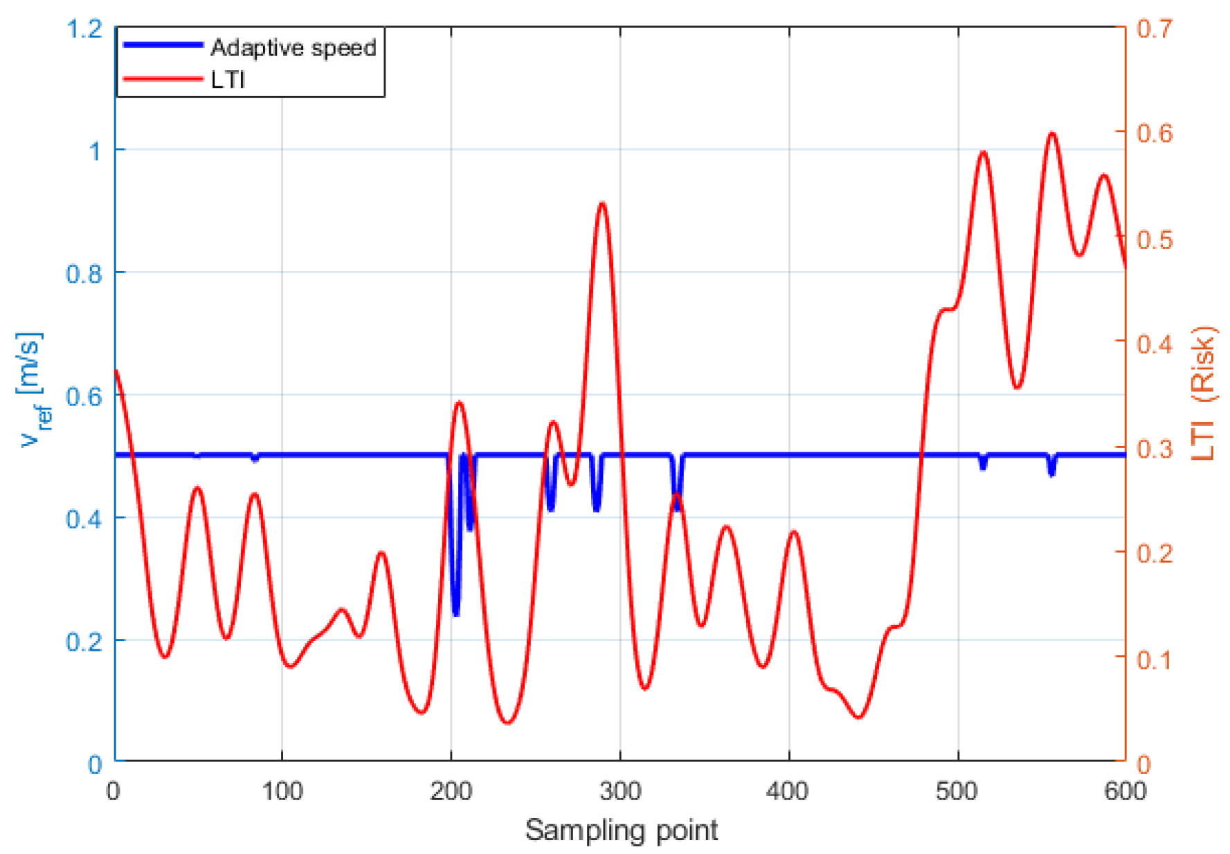
To quantitatively evaluate the local executability of the smoothed path under a given cruising velocity, a Local Trackability Index (LTI) is introduced to describe the execution difficulty of the current path segment under the target velocity condition. Let the preset cruising velocity of the system be
. Then, the LTI at path parameter
u is defined as
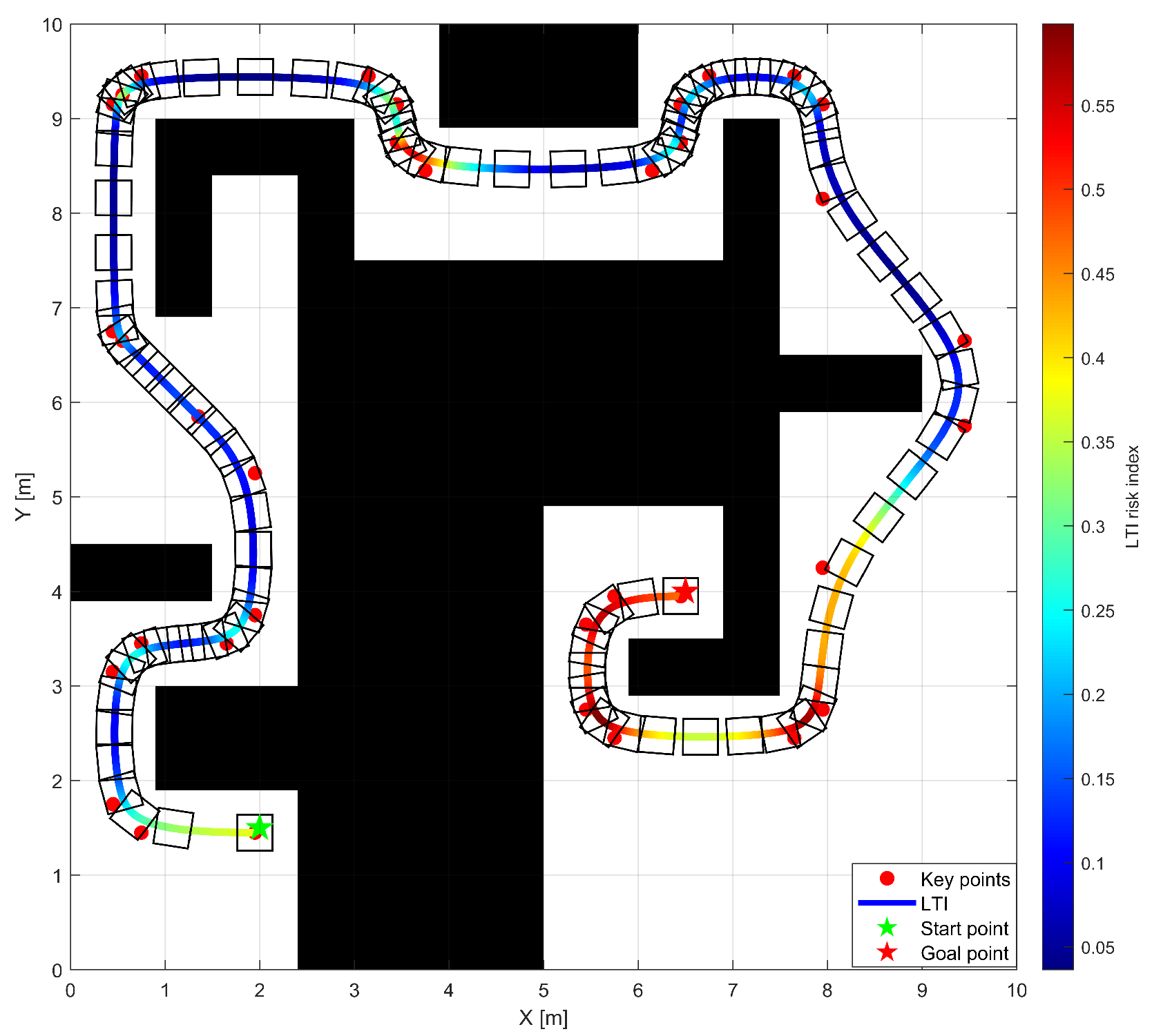
When , the angular velocity required by the corresponding path segment under the current cruising velocity does not exceed the allowable range of the system, indicating that the robot has good trackability in this region. When , however, it indicates that there exists a risk of input saturation in that region. If the current cruising velocity is still maintained, the controller may fail to achieve stable tracking. By computing the LTI distribution along the entire path, the local tracking difficulty of the path can be evaluated, thereby providing a basis for subsequent velocity correction.
It should be noted that the proposed LTI is not introduced as a new control-theoretic law or a fundamentally new kinematic constraint. Instead, it is derived from the classical kinematic relationship among path curvature, linear velocity, and angular-velocity demand of the differential-drive mobile robot. By normalizing the required angular velocity with respect to the allowable angular-velocity bound, the LTI serves as a normalized and interpretable indicator for evaluating the local trackability of the smoothed path under a prescribed cruising velocity. Therefore, its contribution in this study lies mainly in its functional role within the trajectory-generation framework, namely, to identify high-risk regions and to support the subsequent adaptive velocity correction.
On this basis, an adaptive reference velocity correction strategy based on curvature constraints is further constructed. The original upper bound of the velocity at parameter can be defined as
where
is a small positive constant introduced to prevent division by zero. When
approaches zero, the corresponding path segment becomes nearly straight, and the velocity bound
becomes sufficiently large due to the presence of
. In this case, the reference velocity is mainly limited by the prescribed cruising velocity rather than by the angular-velocity constraint.
Accordingly, the original reference velocity at path parameter
u can be defined as
This strategy implies that the robot maintains the cruising velocity in low-curvature path segments to preserve motion efficiency, while automatically reducing the reference velocity in high-curvature regions so that it does not exceed the theoretical upper bound imposed by the maximum angular velocity constraint, thereby avoiding infeasible velocity commands. Considering that local curvature fluctuations may cause frequent variations in the corrected reference velocity and thus deteriorate control input smoothness, a recursive smoothing procedure is further applied to the original reference velocity sequence to obtain the final reference velocity:
where
denotes the velocity smoothing coefficient. To balance the smoothness and responsiveness of velocity adjustment,
is adopted. It should be noted that this recursive smoothing strategy is introduced mainly to reduce abrupt fluctuations in the corrected reference velocity and improve practical smoothness. However, unlike optimization-based methods such as MPC, it does not explicitly impose acceleration or jerk constraints. Therefore, the present treatment should be regarded as a simple smoothing mechanism rather than a strict higher-order motion-constrained trajectory generation strategy.
Accordingly, the reference state at any point on the smoothed path can be further written as
where
denotes the reference heading angle corresponding to the tangential direction of the path. The corresponding reference control input can be written as
At this stage, the originally smoothed path is further transformed into a reference trajectory that contains position, heading, curvature, and velocity information. Unlike methods that focus only on path smoothing, the proposed approach incorporates trackability-constrained analysis and adaptive reference velocity correction, so that the generated trajectory is not only geometrically continuous, but also compatible with the kinematic execution capability of the differential-drive mobile robot. As a result, it provides a more stable and physically reasonable reference input for the lower-level trajectory tracking controller.
3.3. Local Replanning and Trajectory Stitching in Dynamic Environments
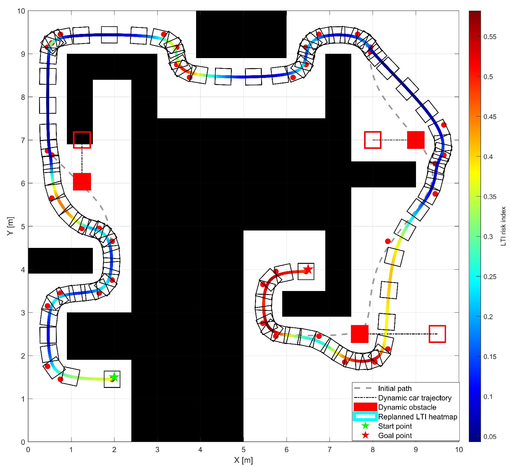
Although the previous two sections have generated a reference trajectory with both geometric continuity and kinematic executability, the whole process is mainly established under the assumption of a static environment. In practical operation, dynamic obstacles may intrude into the original path, causing the reference trajectory to lose local safety and executability. If the robot continues to track the original trajectory, collision risk, emergency braking, or large path deviations may occur. Therefore, a local replanning and trajectory stitching mechanism is further introduced to improve the adaptability of the trajectory to environmental changes. Compared with global replanning, local replanning updates only the affected local trajectory segment, which not only reduces the computational cost of reconstructing the entire path, but also preserves the overall structure of the original reference trajectory as much as possible, thereby alleviating the regulation burden of the lower-level controller. Based on this idea, a “collision-risk triggering–local window updating–smooth trajectory stitching” strategy is adopted to address local path invalidation in dynamic environments.
First, to avoid frequent replanning caused by small disturbances, a rolling prediction window is established ahead of the current reference trajectory, and the collision risk of the local trajectory is evaluated by combining the predicted future positions of dynamic obstacles. Let the set of dynamic obstacles detected at the current time be:
where
denotes the
dynamic obstacle. For obstacle
, let its current position and velocity be
and
, respectively. A constant-velocity model is adopted to approximately predict its position at a future time instant as follows:
where
denotes the prediction time. For any trajectory point
within the forward-looking window of the current reference trajectory, the minimum safety distance from that point to all predicted obstacle positions is defined as:
Let the obstacle safety radius threshold be . When is satisfied, the original reference trajectory is considered to have a potential collision risk in the local region, and local replanning should therefore be triggered. In addition to collision risk, when the deviation between the actual robot state and the reference trajectory exceeds the allowable range, it may also indicate that the current local path is no longer suitable for stable tracking. Accordingly, let the current tracking error be , and let the error threshold be . When is satisfied, local path updating is likewise triggered. Through the above dual mechanism, replanning is performed only when there exists an actual local risk or when the current reference trajectory has become difficult to track stably, thereby avoiding unnecessary frequent updates.
After replanning is triggered, a local window updating strategy is adopted. Specifically, the current robot position is taken as the starting point of local replanning, and a trajectory point located at a certain look-ahead distance along the original reference trajectory is selected as the local target point, thereby constructing a local planning interval that rolls forward in real time with the robot motion. Let the current robot state be , and let the local target point be . Then, the local planning task is implemented using an A*-based search within the rolling local window, where the current robot state is taken as the local start point and the look-ahead point on the original reference trajectory is used as the local target point. The search is performed only in the locally affected map region containing the predicted obstacle occupancy, rather than over the full global map. Since the local update is restricted to a limited trajectory segment, the global target and most of the original path structure remain unchanged.
To ensure that the locally updated path remains suitable for subsequent trajectory tracking control, the discrete path obtained by local replanning is processed in the same manner as described in
Section 3.1. Specifically, key-point sparsification is first performed, followed by cubic B-spline smoothing, so that a new locally geometrically continuous path can be constructed. Meanwhile, in order to prevent the controller from exhibiting significant oscillations due to abrupt changes in the reference input during local trajectory switching, continuity constraints are further imposed on the connection boundary between the original and updated trajectories. Let the triggering instant of local replanning be
, let the state corresponding to the switching point on the original trajectory be
, and let the initial state of the newly generated local trajectory be
. Then, the following boundary consistency conditions are required to be satisfied:
In addition to positional consistency, in order to avoid abrupt changes in orientation or curvature at the switching point, the local trajectory is further required to maintain tangent consistency and curvature continuity at the connection boundary as much as possible. If the original and updated paths are represented in parametric curve form, the corresponding boundary conditions can be written as
where
denotes the parameter value corresponding to the switching position on the original trajectory. The above conditions correspond to positional continuity, tangent continuity, and curvature continuity, respectively. It should be noted that these continuity conditions are not imposed as hard equality constraints directly in the graph-search stage. Instead, after the local discrete path is obtained, the same key-point sparsification and cubic B-spline smoothing procedure described in
Section 3.1 is applied to the locally updated segment. During this process, the boundary states at the entry and exit of the replaced segment are aligned with the original trajectory, so that positional continuity is satisfied explicitly, while tangent consistency and curvature continuity are promoted through boundary-consistent spline fitting. In this way, abrupt geometric transitions at the switching location can be effectively alleviated before the updated segment is stitched back into the original reference trajectory.
After obtaining the new locally smoothed path, the trackability-constrained analysis method described in
Section 3.2 is applied to evaluate its curvature distribution and regenerate the reference velocity profile, so as to ensure that the updated trajectory can avoid obstacles while still satisfying the kinematic execution constraints of the differential-drive mobile robot. Finally, the affected local segment in the original trajectory is replaced by the new local reference trajectory, yielding the updated complete reference trajectory sequence, i.e.,
where
denotes the newly generated local reference trajectory segment, and
and
represent the start and end indices of the replaced segment in the original trajectory, respectively. In this manner, the system can rapidly update and replace the local risk region without compromising the overall navigation objective. From the computational perspective, the proposed local replanning is triggered only when collision risk or excessive tracking error is detected, and the search is limited to a rolling local window rather than the entire map. Moreover, only the affected local segment is re-smoothed and re-parameterized. Therefore, compared with full global replanning, the proposed strategy is more computationally efficient and better suited for online implementation in practical mobile robot systems.
In summary, the local replanning and trajectory stitching mechanism constructed in this study enables the reference trajectory generation process to move beyond one-shot static planning and achieve locally adaptive updating in response to environmental changes. Compared with directly performing global replanning or simply replacing local path segments, the proposed mechanism places greater emphasis on geometric continuity and smooth control execution at the trajectory switching location, thereby allowing the generated reference trajectory to maintain favorable stability and executability in dynamic scenarios.
3.4. Algorithm Flowchart
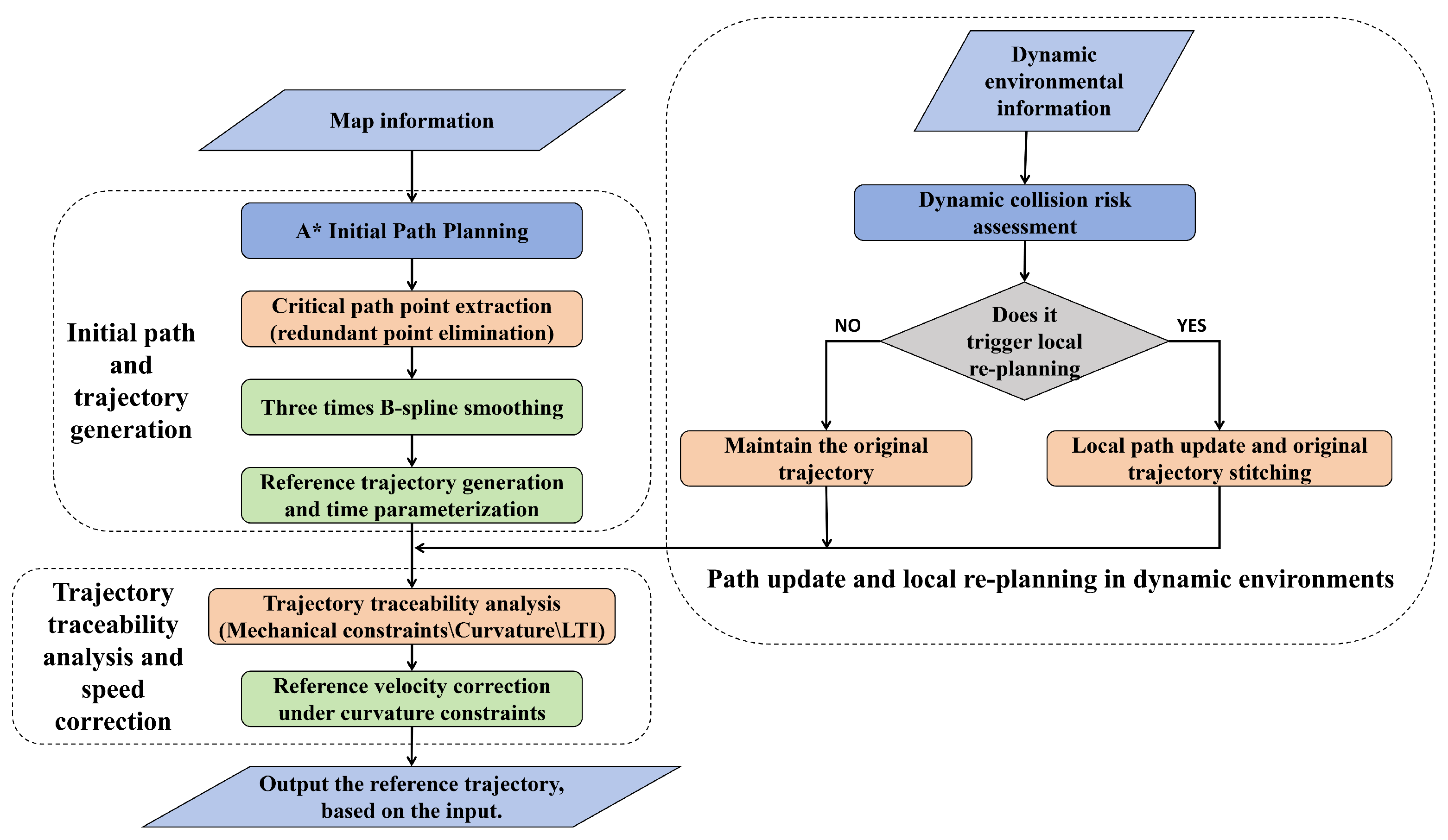
Figure 2 illustrates the overall workflow of the proposed tracking-oriented reference trajectory generation method. The left branch describes the generation process under normal planning conditions. First, map information is used as the input, and A* is employed to generate an initial collision-free path. Then, redundant intermediate nodes are removed through key-point extraction, and cubic B-spline smoothing is applied to construct a geometrically continuous path. Based on the smoothed path, the reference trajectory is generated and time-parameterized. Subsequently, trajectory trackability is evaluated by considering the mechanical constraints, path curvature, and the local trackability index. Finally, the reference velocity is corrected under the curvature constraint, and the executable reference trajectory is output.
The right branch describes the dynamic-environment updating process. When dynamic environmental information is available, the local collision risk is assessed. If the replanning condition is not triggered, the original trajectory is maintained. Otherwise, a local path update is performed, and the updated local segment is stitched with the original trajectory to maintain trajectory continuity. This workflow shows that the proposed method not only improves the quality of the initial reference trajectory, but also supports local trajectory updating when dynamic obstacles affect the original path.
5. Conclusions
To address the difficulty of directly using conventional path planning results for trajectory tracking control, this study proposes a reference trajectory generation method for mobile robots oriented toward trajectory tracking. Starting from an initial collision-free path, the proposed method constructs a geometrically continuous path through key-point sparsification and cubic B-spline smoothing, and further adaptively corrects the reference velocity by considering the kinematic constraints of the differential-drive mobile robot and the local curvature characteristics of the path, thereby generating a reference trajectory with both smoothness and executability. In addition, a local replanning and trajectory stitching mechanism is developed to handle local path invalidation in dynamic environments and improve the adaptability of the reference trajectory to environmental changes.
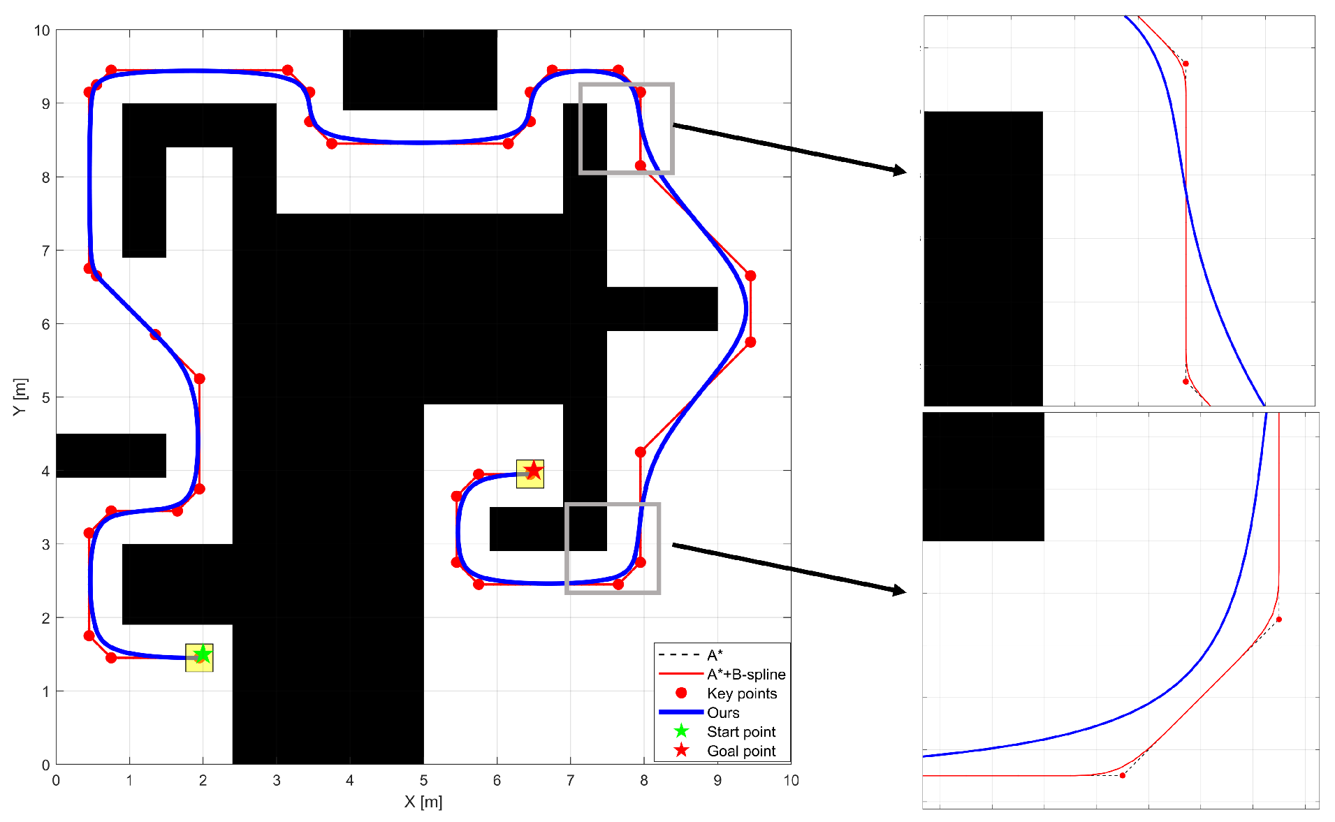
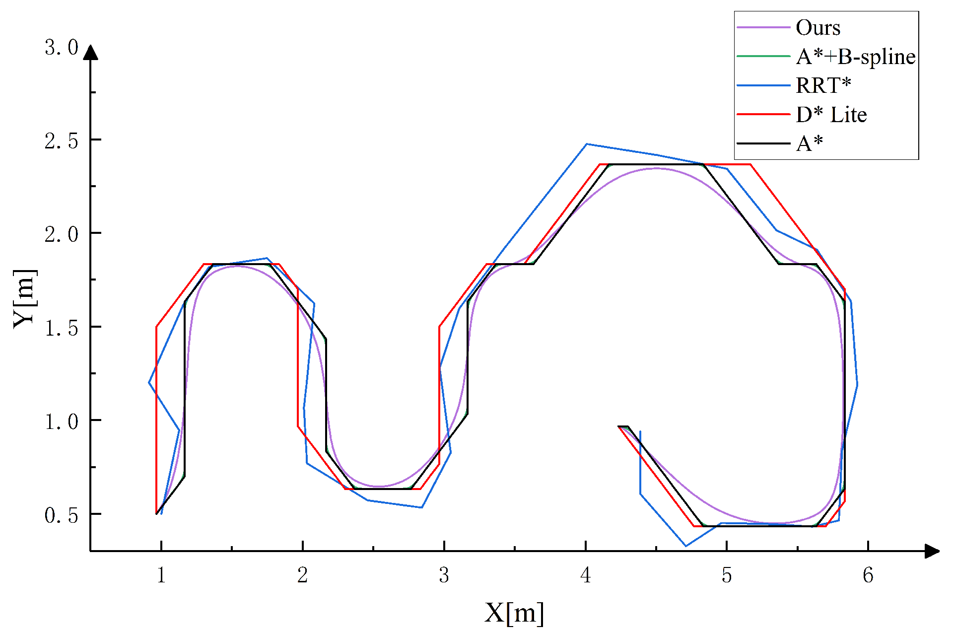
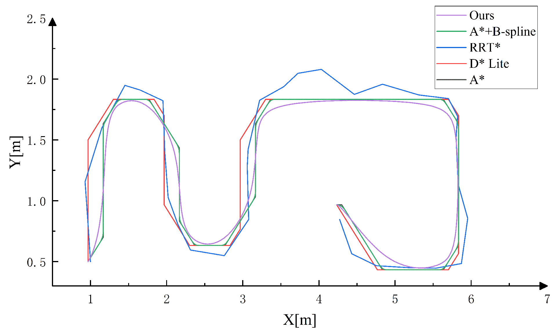
Simulation and real-world experimental results indicate that the proposed method can improve path continuity, reduce abrupt heading changes, and enhance the executability of the reference trajectory in high-curvature regions. In particular, the added node-count comparison shows that the proposed sparsification procedure reduces the original A*-generated path nodes from 130 to 19 in the static environment and from 145 to 23 in the dynamic environment, corresponding to redundancy reduction rates of 85.38% and 84.14%, respectively. Moreover, the proposed method achieves the lowest maximum heading angle change among the compared methods in both environments, indicating smoother directional transitions and better compatibility with the kinematic constraints of the differential-drive mobile robot.
Nevertheless, some limitations of the present study should also be noted. The proposed method is established on the kinematic modeling assumptions of a differential-drive mobile robot, where pure rolling is assumed and lateral slip, skidding, and some complex disturbances are neglected. As a result, the current framework is mainly applicable to reference trajectory generation under relatively moderate operating conditions. In future work, more realistic dynamic effects, uncertainty sources, and stronger environment variations will be considered, and the coupling between reference trajectory generation and lower-level tracking control will be further strengthened.