Article

Parametric Finite Element Analysis and Stress-Sharing Behavior of Friction Ring Springs

1
Doctoral School of Mechanical Engineering and Mechatronics, National University of Science and Technology POLITEHNICA Bucharest, 060042 Bucharest, Romania
2
Faculty of Industrial Engineering and Robotics, Department of Strength of Materials, National University of Science and Technology POLITEHNICA Bucharest, 060042 Bucharest, Romania
3
Faculty of Mechanical Engineering and Mechatronics, Department of Machine Elements and Tribology, National University of Science and Technology POLITEHNICA Bucharest, 060042 Bucharest, Romania
*
Author to whom correspondence should be addressed.
Appl. Sci. 2026, 16(9), 4350; https://doi.org/10.3390/app16094350
Submission received: 13 April 2026 / Revised: 24 April 2026 / Accepted: 27 April 2026 / Published: 29 April 2026
(This article belongs to the Section Mechanical Engineering)

Abstract

This paper presents a finite element study of friction ring springs, with emphasis on the internal stress distribution between inner and outer rings and their damping capacity. A detailed two-dimensional axisymmetric model was developed and compared against experimental measurements, showing close agreement in load–displacement response. In parallel, the classical analytical approach was validated in terms of stress and deformation values. To enable efficient parametric studies, a reduced one-element finite element model representing the periodic structure of the spring was also developed. This simplified model reproduces the response of the complete axisymmetric model while reducing the computational cost by over 80%. Beyond reproducing global mechanical behavior, the study provides detailed insight into the ring interactions as a function of the cone angle, friction coefficient, and the ratio of inner to outer cross-sectional areas. The results show that an optimal design should favor higher circumferential stresses in the inner rings, as their compressive stress state and radial confinement make them more resistant to buckling and crack initiation than the outer rings, which are subjected to tension. The findings provide useful guidelines for the modeling and design of friction ring springs and contribute to the broader understanding of friction-based energy-dissipation systems.

1. Introduction

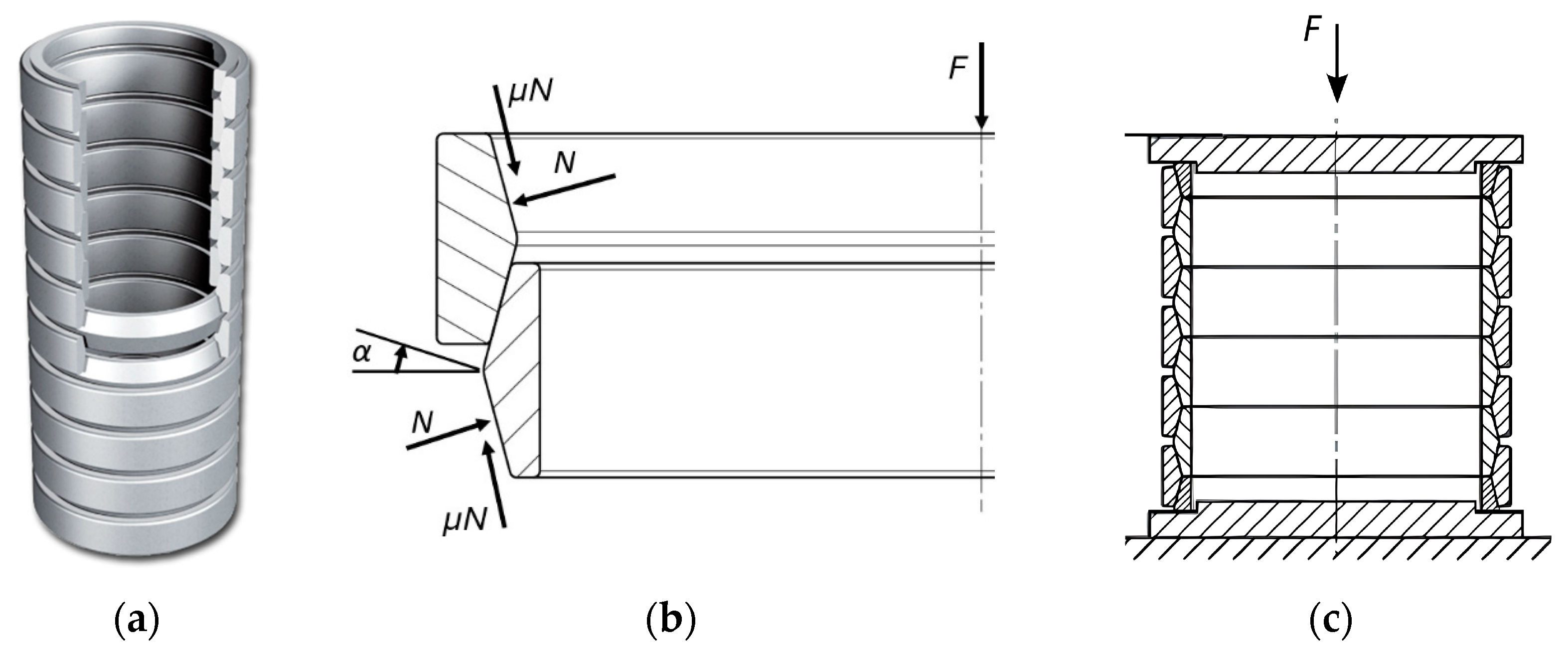
A ring spring (or friction spring) consists of a pack of alternating inner and outer metallic rings, with conically machined mating surfaces [1] (Figure 1). First introduced and patented in 1922 by Dr. Ernst Kreissig [2], they are used in engineering applications where high energy dissipation and relatively compact dimensions are required: railway car coupler buffers and frontal impact buffers, steel mill end stops, dampers for building seismic protection, recoil systems in military cannons and weapons, aeronautical airbrakes and emergency doors.
When the stack is subjected to a vertical force F, the rings start sliding against each other on the inclined surfaces, determining the appearance of two forces at the level of each common surface: a normal force N and a friction force µN, in which µ is the friction coefficient (Figure 1). The inner rings are deformed inwardly, in compression (hoop compressive stress), and the outer rings are deformed outwardly, in tension (hoop tensile stress). When reaching the compression limit, the inner rings will contact each other, resulting in the sudden increase in the stiffness of the spring; at this point, the ring stack will act like a single solid cylindrical body.
Early studies by Wikander [4,5] introduced analytical formulations and experimental hysteresis diagrams, while Endsley [6] reported their application as railway draft gear springs. In the late 1960s, experimental results [7,8] confirmed their favorable shock isolation characteristics for missile construction. Towards the end of the century, ring springs gained attention in civil engineering, especially for seismic and vibration isolation. The works of Erasmus [9] and Hill [10] confirmed their effectiveness in the seismic and vibration protection of buildings. Filiatrault et al. [11] proposed a prototype damper incorporating friction springs and performed a shaking table experimental study, with results showing a reduced the peak displacement response of the structure. Bishay and Carr [12] further investigated the use of ring spring dampers as a passive control system for seismic protection, demonstrating reduced roof displacements and inter-story drifts, without increasing structural accelerations. Issa et al. [13] proposed and tested a novel piston bracing system incorporating single and double ring spring. Experimental and numerical investigations showed that these devices provided stable, repeatable hysteretic behavior, with good self-centering ability, while also drastically improving the seismic energy dissipation. Wang et al. [14] investigated the influence of different surface conditions of the conical contact surfaces of the rings, including the presence or absence of lubrication and dry shot blasting. They reported that the latter one produced the highest coefficient of friction, which lead to increased yield load and energy dissipation.
In railway engineering, ring springs remain widely used, especially as impact buffers. Nesovic [15] compared analytical predictions based on thin-walled body theory with results from an early finite element model, reporting good agreement, and also emphasized the axisymmetric nature of both the ring spring construction and the applied load. Further numerical studies were carried out by Skup [16], who validated analytical models against both experimental results and numerical simulations for generic energy dissipators, and by Ling et al. [17], who developed a 3D finite element model to verify proposed stress calculation formulas for thick-walled ring springs.
Khoo et al. [18,19] introduced a self-centering sliding beam-to-column connection that incorporates a friction spring device at the bottom flange of the beam. Experimental testing demonstrated stable and repeatable hysteretic performance with negligible damage to the floor system. The use of super elastic shape memory alloys to enhance the energy dissipation capacity of structural connections has been proposed and investigated by Fang et al. [20], Wang et al. [21], and Spaggiari [22]. Although these materials were proven promising, their high manufacturing cost outweighed their potential benefits. Dragoni [23] introduced a step-by-step optimization algorithm for the design of ring springs, based on classical thin-walled body theory. This method provides a systematic alternative to the conventional trial-and-error design approach. Lastly, Kong et al. [24] experimented with a three-layer ring spring self-centering energy dissipation device and observed that the load-carrying capacity improved when the stiffness distribution between inner and outer rings shifted from a series-like to a parallel-like behavior.
Friction-based mechanical systems are widely used for energy dissipation due to their relatively simple construction and high damping capacity, with the response governed primarily by dry friction at the contact interfaces. However, the presence of friction introduces a degree of nonlinearity in the mechanical behavior of the system, particularly under cyclic loading conditions, making analytical modeling difficult. For this reason, numerical approaches such as finite element analysis are frequently used to capture the complex phenomenon at the contact level, as highlighted in recent studies on friction-based damping devices with a helical cut shell for drilling equipment [25,26].
The aim of this paper is to narrow the gap between analytical formulations, numerical modeling and experimental procedures in the study of friction ring springs. This is achieved by directly comparing results obtained from these three approaches, using a methodology inspired by the cited literature. While the analytical formulas provide very good results, the numerical model offers a more accurate representation of the real behavior of the spring. In addition, the paper investigates the internal stress distribution between the inner and outer rings and proposes efficient finite element modeling strategies for parametric analysis.

2. Axisymmetric Finite Element Model

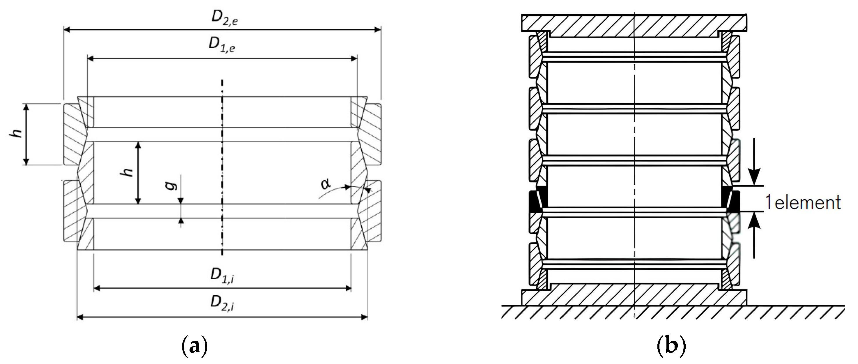
The general geometrical characterization of the ring elements are depicted in Figure 2 and consists of: the inner and outer diameters of the inner (D1,i and D2,i) and outer rings (D1,e and D2,e), the ring height (h), the contact cone angle (α) and the gap between two neighboring rings in initial state (g); n represents the total number of elements. These values together with the elastic material properties, Young’s modulus (E) and Poisson’s ratio (ν) are shown in Table 1. In the literature, a representative concept for the study of friction springs is the pair of adjacent conical friction surfaces termed ‘1-element’ (Figure 2) that represents a structure with linear periodicity and axial symmetry. It can be more easily explained as the common surface between two (half) neighboring rings. The total number of elements is represented through the parameter n.
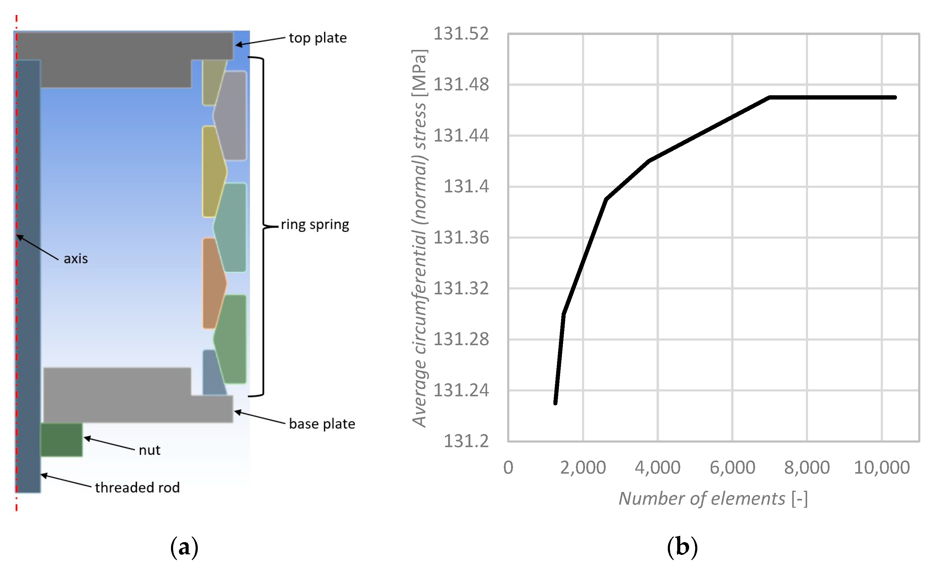
The aim of this numerical model is to replicate the experimental conditions and results while being as simple and as fast as possible. An axisymmetric model using the software Ansys Workbench 2025 R2—Student Edition was developed, employing PLANE183 quad elements (Figure 3), with eight nodes, each node having two degrees of freedom (radial and axial translations). The contacts between the inner and outer rings and between the two end rings and the top and base plates are modeled as line-to-line contact pairs with Coulomb friction (equal friction coefficient), allowing realistic normal pressure distribution and sliding behavior to be captured.
A mesh convergence study was conducted by varying the element size in the rings from 0.4 mm (10,353 elements) to 4 mm (1257 elements) while monitoring the average circumferential (normal) stress in the middle outer ring when a constant vertical force is applied on the top plate. As shown in Figure 3, the monitored stress varies by less than 0.24 MPa (≈0.18%) across the tested meshes. Meshes coarser than 4 mm failed to produce a converged solution due to insufficient discretization of the contact surfaces and poor geometry resolution for the frictional contact algorithm. Based on these results, a mesh with element size 0.5 mm (6992 elements) was selected for work as it provides mesh-independent results with acceptable computational cost.

3. Experimental Setup and Results

Experimentally, three quasi static vertical loading and unloading tests were performed using a pack of 7 Ringfeder® type 16600 rings (4 interior ones and 3 exterior ones).
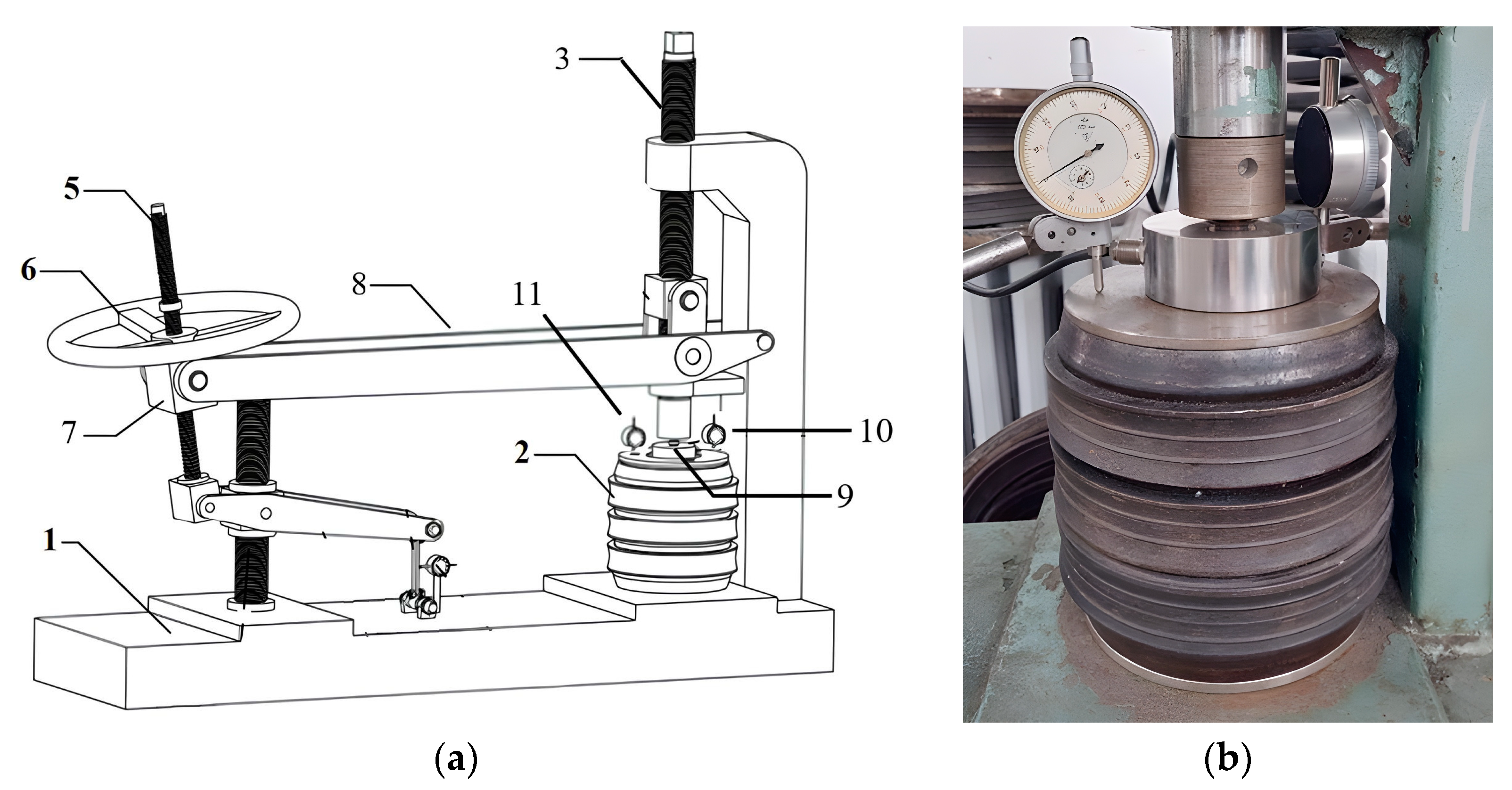
The experimental setup and the spring are presented in Figure 4. The rigid base plate (1) supports the ring pack (2). Force is generated with the help of the wheel (6), the threaded rod (5) and the ball powered screw and articulated nut (7), and it is transmitted to the ring spring via the amplification lever (8) and the vertical rod (3). The generated force is measured with a compression load cell CBL10000 (9) with 0.03% accuracy and the deformation of the ring spring with the dial comparators (10) and (11), with an accuracy of 0.01 mm. As expected, the end surfaces of the ring pack are not perfectly parallel; therefore, the two dial indicators are positioned along the direction of maximum slope of the top plate.
The state of the contact surfaces between the rings has a direct influence on the ring spring. Due to the conditions in the testing environment (namely the ring surface quality, the grease lubrification of the pack and the preload of 1000 N), the coefficient of friction between the contacting faces cannot be determined with high accuracy. This is further complicated by the fact that frictional contact exhibits nonlinear behavior and depends on multiple factors such as load, surface condition and relative displacement [27]. To account for this uncertainty, the experimental results are compared with numerical predictions obtained for a range of friction coefficients. This approach highlights the sensitivity of the system to friction and emphasizes its importance as a design parameter. Values of the kinetic friction coefficient for steel/ steel are between 0.1 and 0.3 [1,20], but most often the value adopted in the cited bibliography is 0.1.
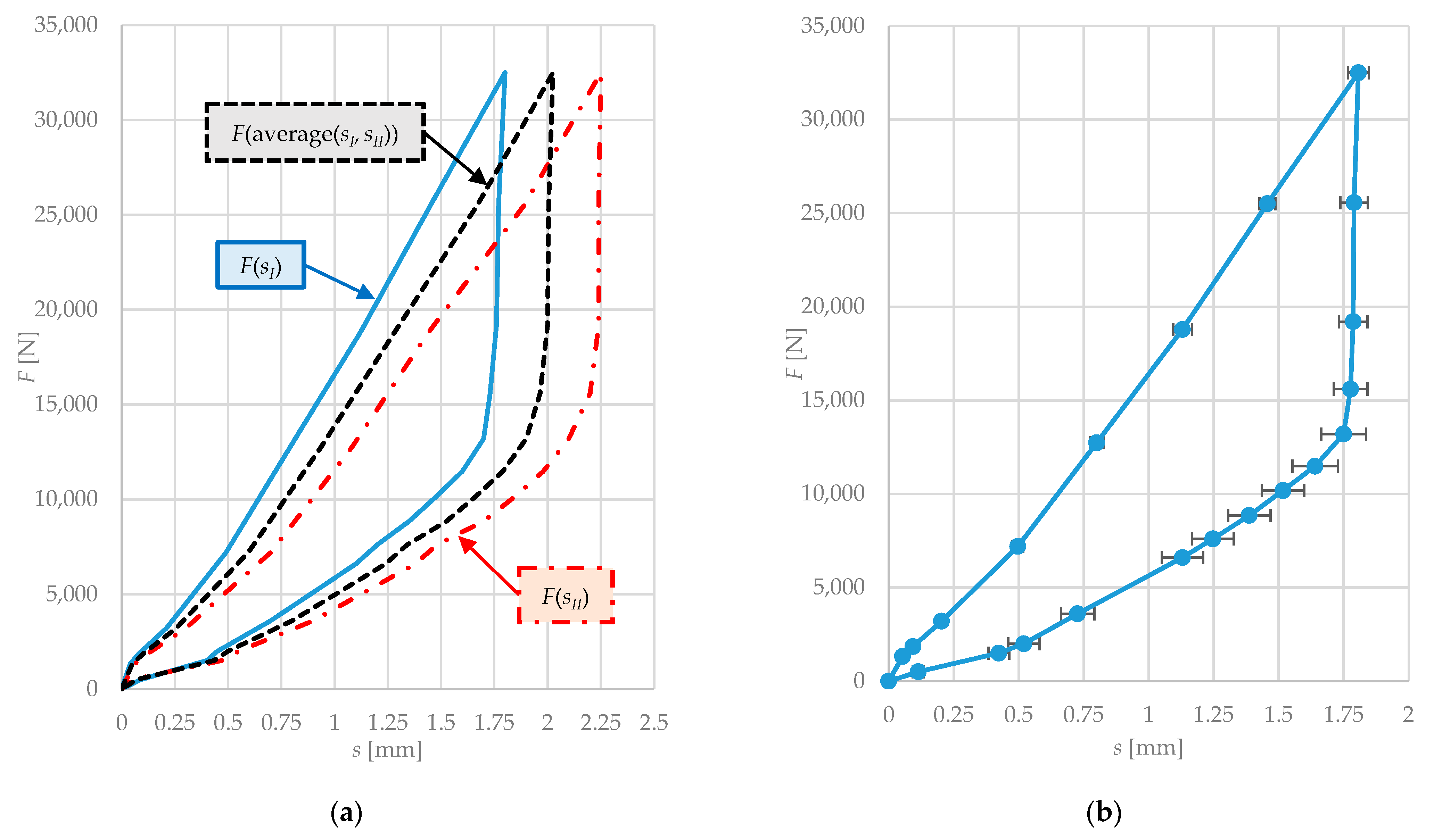
Figure 5a shows the readings of the two dial comparators for a representative loading case. The observed difference between the measurements indicates that the top loading plate, and consequently the ring pack, experienced a slight angular misalignment during the compression tests. To account for this effect, an additional characteristic curve was defined, expressing the vertical force F as a function of the average displacement: (sI + sII)/2.
In Figure 5b, the error bars represent the standard deviation of the three experimental measurements, highlighting the repeatability of the test results. The relatively small deviations indicate good consistency of the experimental setup and confirm the reliability of the measured response.

4. Results Comparison and Model Validation

4.1. Numerical Versus Analytical Results

The finite element model described previously was adapted to match the geometry of the rings used in the experimental setup. A maximum vertical load of 32,500 N was applied, with the coefficient of friction varying within the range µ = 0.10–0.14.
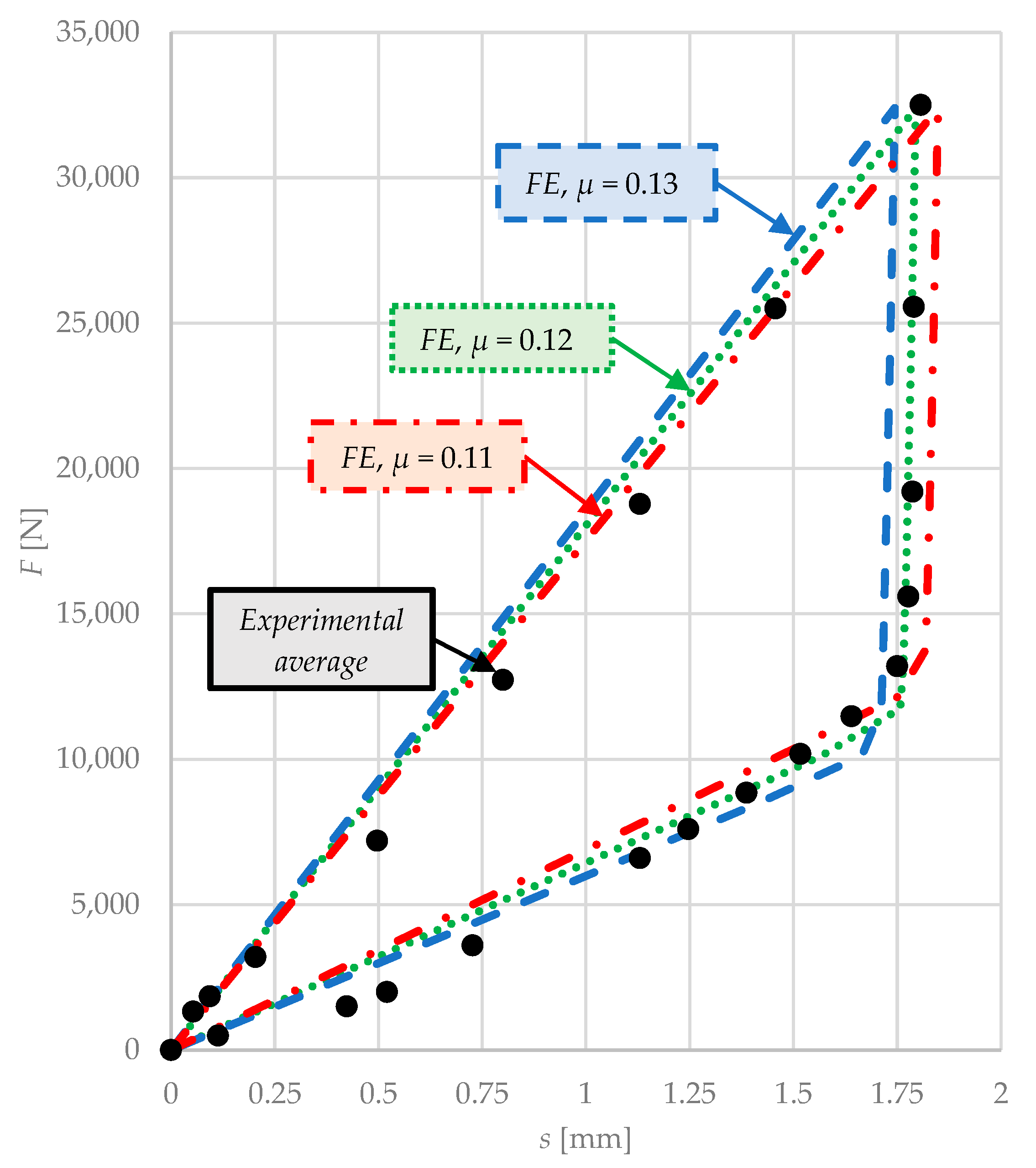
Figure 6 compares the finite element (FE) characteristic curves with the average experimental one. The experimental curve falls within the range defined by the numerical predictions for µ = 0.11–0.13, indicating a good agreement between the model and the measured response. An approximation of µ = 0.12 is therefore obtained. This approach allows the uncertainty associated with contact conditions to be accounted for, providing a more realistic validation approach compared to using a single friction value.
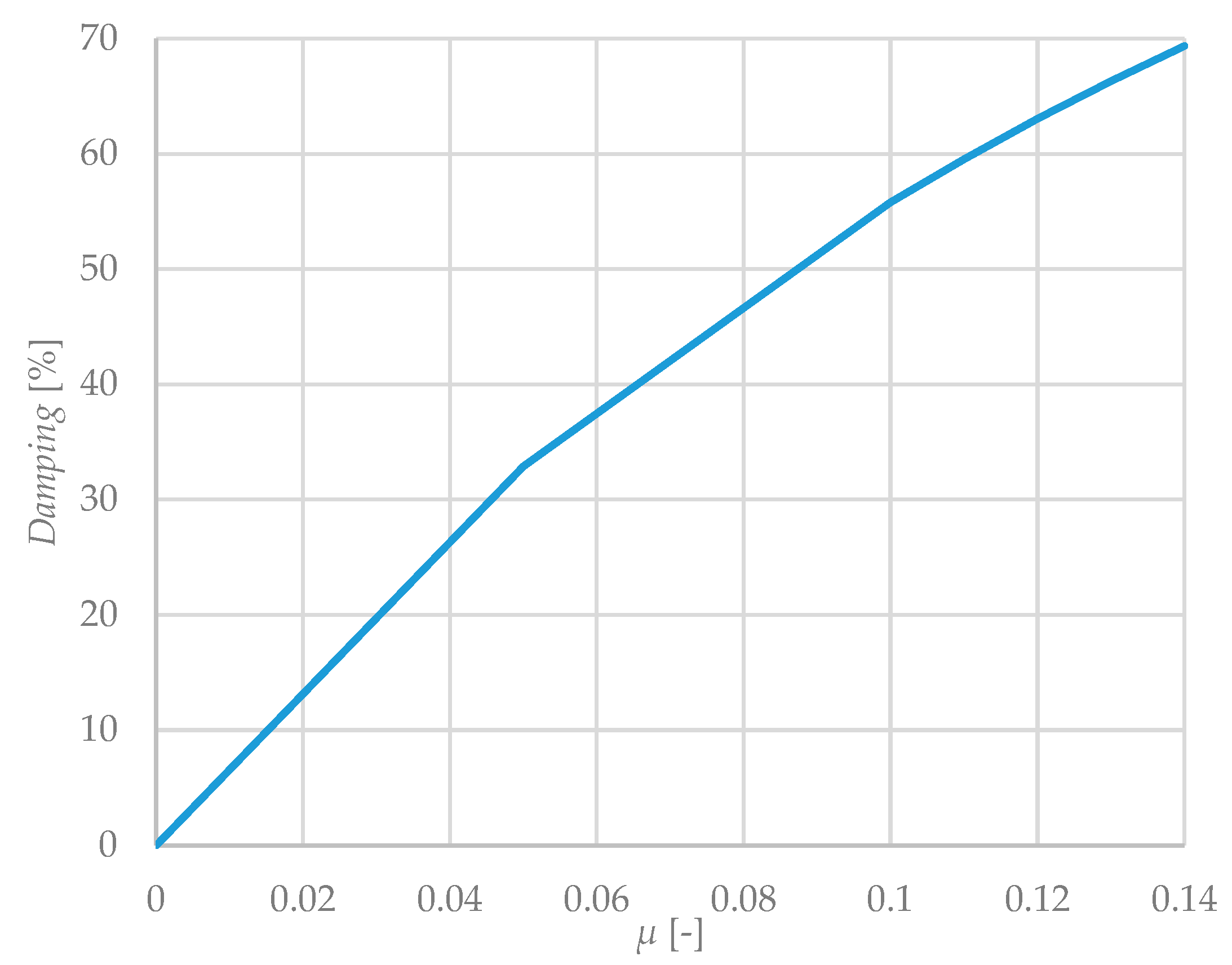
The damping capacity is defined as the energy dissipated during one loading–unloading cycle, represented by the area enclosed by the load–displacement hysteresis loop. By evaluating the damping capacity of the ring spring corresponding to each value of µ (Figure 7), it is observed that the relationship between damping and the friction coefficient is not strictly linear, as the slope of the curve decreases with increasing µ. Although the damping capacity increases with friction, the rate of increase becomes progressively smaller as the friction coefficient grows. According to [3], the maximum energy dissipation capacity of friction springs can reach values as high as 66%, which corresponds to approximately µ = 0.12—the value closest to reality when the theory is superimposed with the experiments.
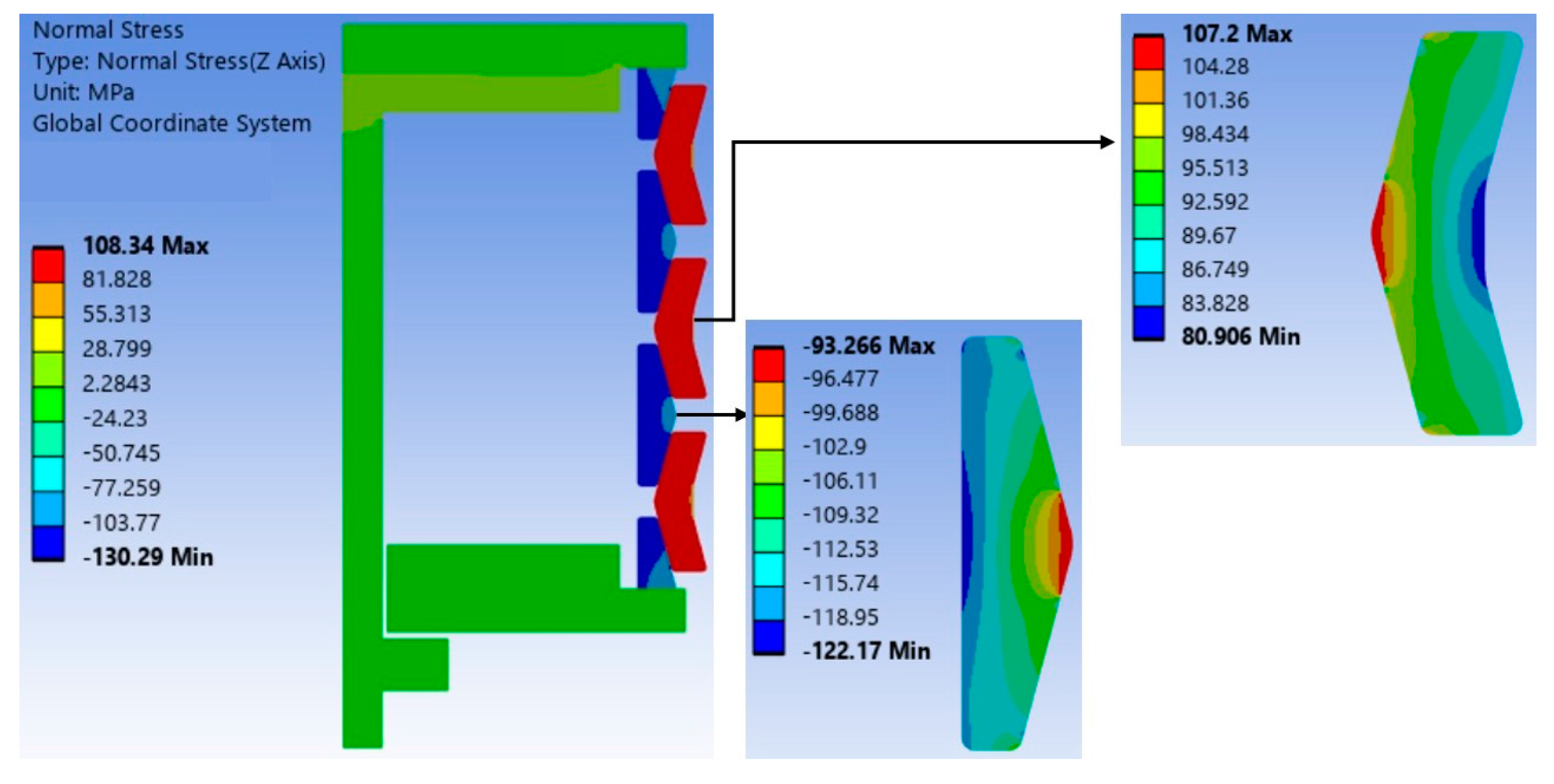
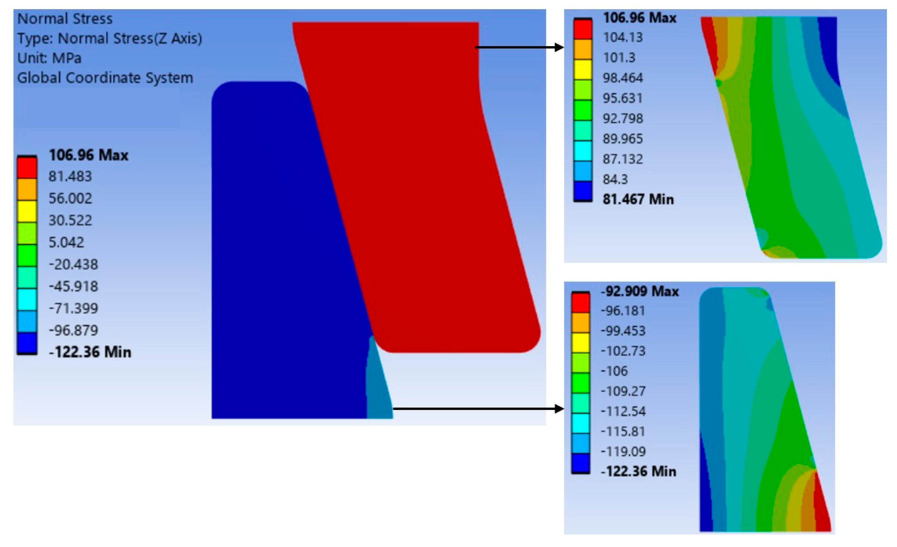
The circumferential stress distributions obtained from the finite element model are presented in Figure 8. Three main observations can be made:
  • Circumferential stress is not constant through the wall thickness of the rings, but varies significantly (a difference of around 25 MPa between the outer and inner limits).
  • Excepting the two end rings, the stress level is the same across the pack (for each type of ring), further emphasizing the periodic character of the structure.
Figure 8. Circumferential stress distribution in the complete numerical model for µ = 0.14.
Applsci 16 04350 g008

4.2. Analytical Model Validation

The results obtained from the finite element simulations were used in the evaluation of the analytical model available in the literature [1,15]. For clarity, this model is briefly presented in the following section.
The stress and displacement expressions follow the thin-walled body theory, which forms the basis of most references in the literature. This approach is attractive because of its simplicity, but it relies on several simplifying assumptions: the wall thickness is much smaller than the radius (r/t ≥ 10), stresses are uniform through the thickness (plane-stress), the applied loads are uniformly distributed, deformations remain small (linear elasticity), and buckling effects are neglected. Thus, the expression for the maximum stress of the inner rings is
σ i = F π   A i     1 μ   t a n ( α ) tan α + μ
in which Ai represents the axial cross-section area of the inner ring.
Similarly, for the outer rings, the maximum hoop tensile stress is
σ e = F π   A e     1 μ   t a n ( α ) tan α + μ
in which Ae represents the axial cross-section area of the outer ring.
The total displacement of the ring spring can be evaluated with the following expression:
s = n   σ i   D m , i + σ e   D m , e 2   E   t a n α
in which Dm,i and Dm,e are the mean diameters of the inner and outer rings.
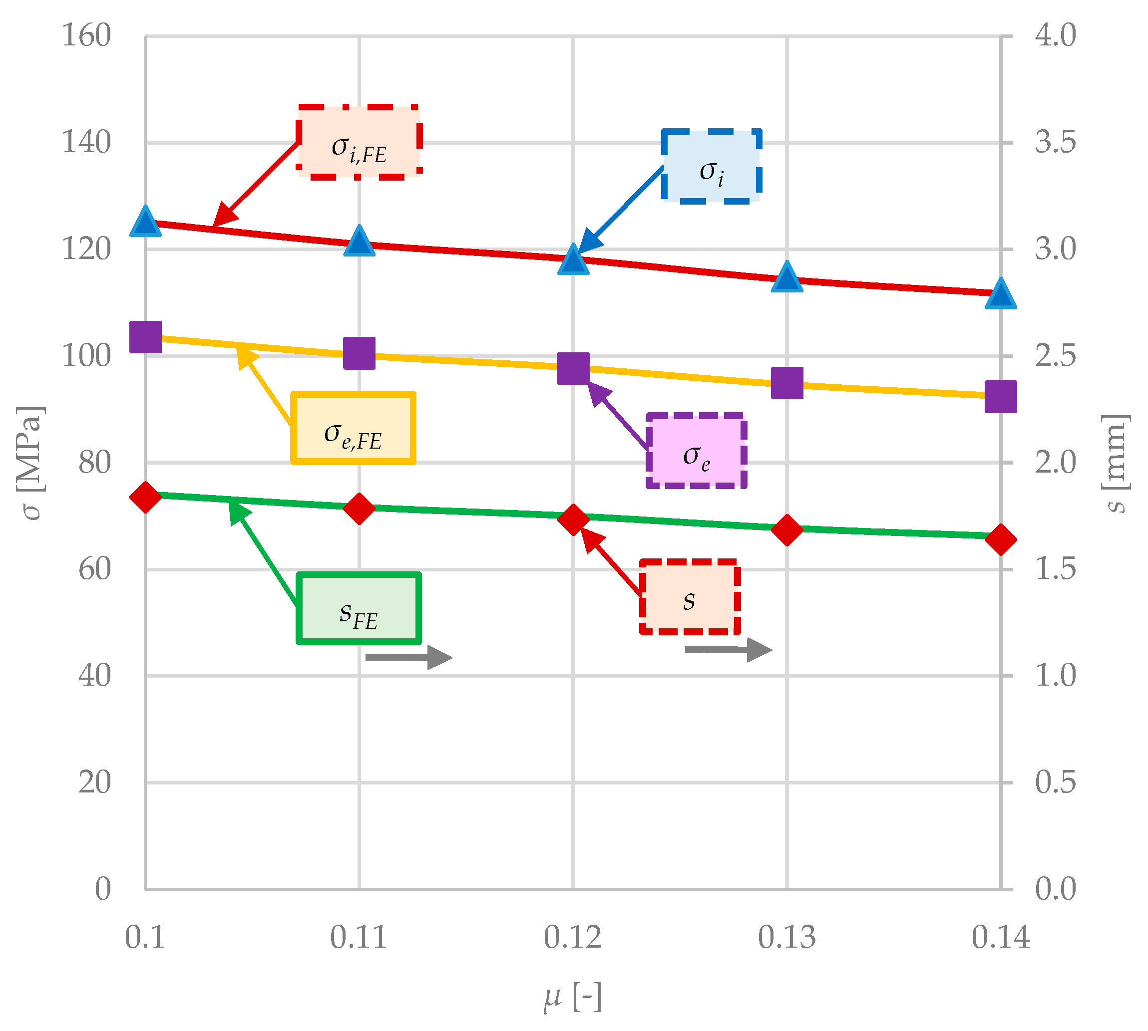
Using the formulas above, the analytical stress in the inner and outer rings is calculated, considering the same friction coefficient interval µ = 0.10–0.14.
In Figure 9, the analytical predictions for stress and displacement are compared with the average finite element results. The two sets of results overlap almost entirely, indicating excellent agreement between the analytical model and the numerical simulation. The analytical formulas capture only the average ring stress across the section, whereas the maximum local stresses predicted by the numerical model are higher, although still well below the material yield limit.
The formulas used in this section offer satisfying results for the provided ring geometry, but the numerical model offers more realistic local stress information than the analytical approach.

5. Parametric Studies

In order to further simplify the model, the complete model from the previous section has been reduced to the representative one-element periodic concept (a pair of contacting half-rings, Figure 2), in the same manner as [15]. The boundary conditions were updated, and the stress distribution results are presented in Figure 10.
As shown in Figure 10, the one-element model reproduces the stress distributions and values of the full model with high accuracy (relative differences of 1.3%), while reducing the number of elements and computational time by approximately 80%. This demonstrates that the approach is both efficient and reliable for the analysis of ring spring assemblies with an arbitrary number of rings.
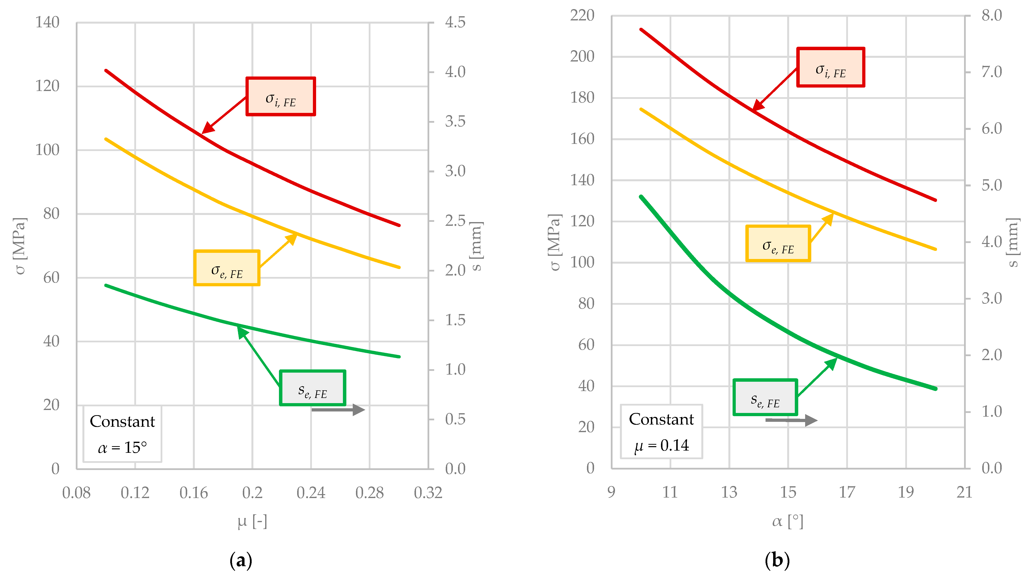
Several sensitivity analyses are completed next, in order to observe the influence of the key parameters (such as the coefficient of friction, the contact cone angle, and the cross-section area) on the displacement and stress in the inner and outer rings, while maintaining the vertical load constant. As before, the values for stress represent the average value for the corresponding ring.
Figure 11a shows that both the stresses in the spring components (σi and σe) and the displacement (s) decrease as the friction coefficient (µ) increases. As the displacement decreases, so does the area of the hysteresis loop of the spring, which, in turn, translates to a decrease in the energy dissipating ability (a conclusion confirmed also by the work of Skup [16]).
Figure 11b illustrates the influence of the contact cone angle α on stress and displacement: as the angle increases, both quantities decrease in a similar manner. For this analysis the section areas of the parts were kept constant while changing the values of the angle α. The friction µ and the cone angle α are closely related: α should always have a greater value than the friction angle φ (defined by tan(φ) = µ); otherwise, the spring can no longer return to its original position during the unloading phase. In turn, a lower value of the cone angle coupled with a bigger friction coefficient could cause prominent residual deformations due to the insufficient restoring force to overcome the friction effect.
This behavior is consistent with the observations in Figure 7, where higher values of the friction coefficient increase the damping capacity but also reduce the ability of the system to recover. Consequently, excessive friction or insufficient cone angle may lead to the partial locking of the ring spring and the development of residual deformations, due to the inability of the restoring force to overcome frictional resistance.
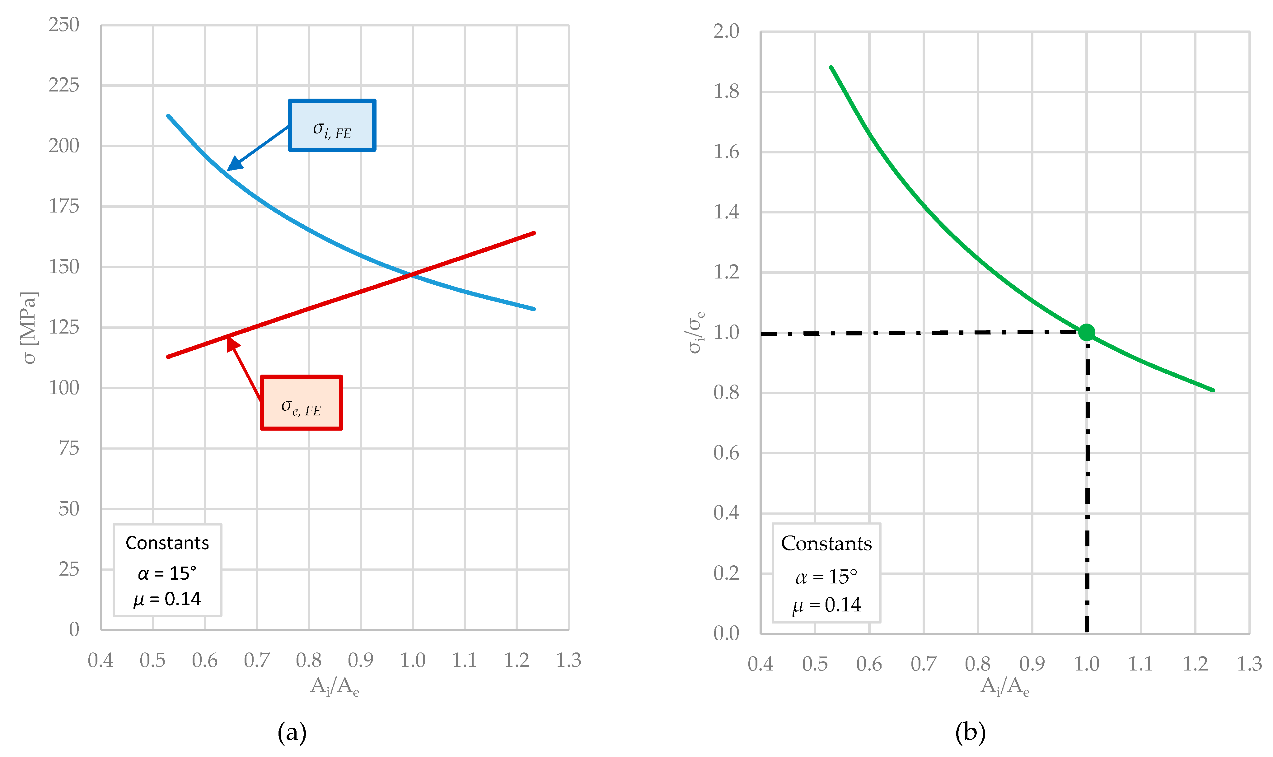
Figure 12a presents the maximum circumferential stresses in the two rings as a function of the ratio of their cross-section areas (Ai/Ae). In this parametric study, the cross-section of the inner ring was gradually increased while the outer ring cross-section was kept constant. The results indicate a progressive transfer of load:
  • When the inner ring has a smaller cross-section than the outer ring (Ai/Ae < 1), it carries a greater proportion of the circumferential stress.
  • As Ai/Ae approaches unity, the stresses in the two rings tend to equalize.
  • For Ai/Ae > 1, the outer ring gradually assumes the larger share of the load.
Therefore, increasing the cross-sectional area of either ring reduces its corresponding material stress, since the same load is distributed over a larger section. This trend is consistent with both mechanics of materials and previous findings in the literature [17].
Figure 12. Influence of the cross-sectional area ratio Ai/Ae on stresses and stress ratio: (a) circumferential stresses in inner and outer rings; (b) stress ratio σi/σe highlighting the equilibrium point.
Applsci 16 04350 g012
Figure 12b illustrates the same trend in a more compact form, by plotting the ratio of the maximum circumferential stresses in the inner and outer rings, σi/σe, as a function of Ai/Ae. This representation highlights the intersection point, where the stress ratio (and cross-sectional area ratio) equals unity, i.e., both rings carry similar stress levels.
For the rings used in this study, the cross-section ratio Ai/Ae of approximately 0.83 reflects a deliberate design choice of the manufacturer for the inner ring to carry the greater share of material stress. This conclusion originates from Figure 12 and can be interpreted from a mechanical strength and durability standpoint, with several arguments supporting this configuration.
Firstly, for steel alloys, the yield strength in tension and in compression might differ. Depending on the material, they can be of the same magnitude, or the compressive strength greatly surpasses the tensile one, but compressive states are less prone to crack initiation and surface damage [28]. Secondly, the inner rings from a ring pack are laterally supported by the mating outer rings and by the stack geometry.
According to [29], this radial confinement increases the higher critical load-carrying capacity, surpassing a free-standing compressed ring or an outer ring carrying tensile hoop strength. Furthermore, this radial support increases radial stiffness and raises the buckling resistance of circumferentially compressed parts by providing lateral restraint, a mechanism also observed by Sun et al. [30] in their study of composite pipes under radial compression.
By analyzing Figure 12, it is evident that, beyond obvious parameters such as friction coefficient and contact cone angle, the part thickness or material distribution of each ring plays an important role in ensuring a reliable and mechanically robust ring spring design.

6. Conclusions

The work presented here advances the numerical modeling of ring springs by combining analytical formulations, experimental testing and finite element simulations. Beyond reproducing global hysteretic behavior, the study highlights the internal stress distribution between inner and outer rings and demonstrates the usefulness of the reduced one-element model for design studies. The principal conclusions are outlined below:
  • An axisymmetric finite element model with contact and friction formulation was developed and compared against both analytical and experimental results. The analytical formulas provide very good results (relative differences of 1.3%); however, the numerical model offers a more accurate representation of the real ring state and behavior.
  • The reduced single-element finite element model enables efficient parametric studies of the complete ring spring, which can be regarded as a one-dimensional periodic structure with reflective symmetry. It is also readily customizable through simple geometric parameterization, making it suitable for sensitivity analyses and design optimization across multiple ring spring types.
  • The relationship between the damping capacity and the friction coefficient is quasi-linear, as the damping capacity increases clearly with the friction coefficient, although the rate of increase progressively diminishes.
  • The contact cone angle α and the friction coefficient µ have a strong and coupled influence on the mechanical response of the ring spring. While increasing either parameter reduces peak stresses and enhances energy dissipation, the condition α > φ = atan(µ) must be satisfied to ensure proper re-centering. Otherwise, excessive friction may lead to partial locking of the spring and the development of residual deformations.
  • The material distribution between the inner and outer rings (expressed here by the cross-section area ratio of the rings) determines which part carries the greater share of the total stresses.
  • The results demonstrate that the inner ring should ideally carry the greater portion of the circumferential stress, as its compressive state, radial confinement, and increased buckling resistance make it mechanically more favorable and less prone to crack initiation.

Author Contributions

Conceptualization, T.C.; software, M.C.; validation, Ș.S.; formal analysis, M.C. and T.C.; writing—original draft preparation, M.C.; writing—review and editing, M.C. and T.C.; visualization, Ș.S.; supervision, Ș.S. All authors have read and agreed to the published version of the manuscript.

Funding

This research received no external funding.

Institutional Review Board Statement

Not applicable.

Informed Consent Statement

Not applicable.

Data Availability Statement

The raw data supporting the conclusions of this article will be made available by the authors on request.

Acknowledgments

The authors would like to thank Ionuț-Răzvan Nechita, Petrică Turtoi and Mihai Rozorea for their assistance in setting up the experiments. The publication of this work was supported by the National University of Science and Technology POLITEHNICA Bucharest through the PubArt program.

Conflicts of Interest

The authors declare no conflicts of interest.

Nomenclature

Aaxial cross-section area [mm2]
Ddiameter [mm]
EYoung’s modulus [MPa]
Fvertical force [N]
ggap between two rings [mm]
hring height [mm]
Nnormal force [N]
rradius [mm]
sdisplacement [mm]
tthickness [mm]
αcone angle [°]
µfriction coefficient [-]
νPoisson’s ratio [-]
σstress [MPa]
φfriction angle [°]

Subscripts

1inner diameter
2outer diameter
eouter ring
FEfinite element
iinner ring
maverage

References

  1. Brown, A.A.D.; Spring Research and Manufacturers’ Association (UK). Mechanical Springs/A.A.D. Brown on Behalf of the Spring Research and Manufacturers’ Association, 1st ed.; Oxford University Press: Oxford, UK, 1981; pp. 34–39. [Google Scholar]
  2. Meissner, M.; Fischer, F.; Wanke, W.; Plitzko, M. Die Geschichte der Metallfedern und der Federntechnik in Deutschland; Universitätsverlag: Ilmenau, Germany, 2009; pp. 147–148. ISBN 978-3-939473-64-0. [Google Scholar]
  3. Product Paper RINGFEDER® Damping Technology. Available online: https://www.ringfeder.com/downloads/ (accessed on 31 March 2026).
  4. Wikander, O.R. Characteristics of the ring spring. Am. Mach. 1924, 60, 253–254. [Google Scholar]
  5. Wikander, O.R. The ring spring. Mech. Eng. 1926, 48, 139–143. [Google Scholar]
  6. Endsley, L.E. Draft gear springs—Past and present. Railw. Mech. Eng. 1933, 107, 253–255. [Google Scholar]
  7. Eshleman, R.L.; Rao, P.N. The response of mechanical shock isolation elements to high rate input loading. Shock Vib. Bull. 1969, 40, 217–234. [Google Scholar]
  8. Eshleman, R.L. Dynamic response of a ring spring. Shock Vib. Bull. 1972, 42, 7–14. [Google Scholar]
  9. Erasmus, L. Ring springs on holding-down bolts for seismic energy dissipation. IPENZ Trans. 1988, 15, 41–47. Available online: https://search.informit.org/doi/abs/10.3316/informit.375952756500588 (accessed on 31 March 2026).
  10. Hill, K.E. The Utility of Ring Springs in Seismic Isolation Systems. Ph.D. Thesis, University of Canterbury, Christchurch, New Zealand, 1995. [Google Scholar]
  11. Filiatrault, A.; Tremblay, R.; Kar, R. Performance evaluation of friction spring seismic damper. J. Struct. Eng. 2000, 126, 491–499. [Google Scholar] [CrossRef] [Scilit]
  12. Bishay-Girges, N.W.; Carr, A.J. Ring spring dampers: Passive control system for seismic protection of structures. Bull. N. Z. Soc. Earthq. Eng. 2014, 47, 173–180. [Google Scholar] [CrossRef] [Scilit]
  13. Issa, A.S.; Alam, M.S. Seismic performance of a novel single and double spring-based piston bracing. J. Struct. Eng. 2019, 145, 04018261. [Google Scholar] [CrossRef] [Scilit]
  14. Wang, W.; Fang, C.; Zhao, Y.; Sause, R.; Hu, S.; Ricles, J. Self-centering friction spring dampers for seismic resilience. Earthq. Eng. Struct. Dyn. 2019, 48, 1045–1065. [Google Scholar] [CrossRef] [Scilit]
  15. Nešović, J. Design and calculation of ring springs as spring elements of the wagon buffer. Facta Univ. Ser. Mech. Eng. 2002, 1, 1127–1133. [Google Scholar]
  16. Skup, Z. Theoretical and experimental studies of energy dissipation in a model of a ring spring. J. Theor. Appl. Mech. 2007, 45, 363–377. [Google Scholar]
  17. Ling, Y.; Wu, S.; Gu, J.; Lai, H. A novel ring spring vibration isolator for metro superstructure. Appl. Sci. 2021, 11, 8422. [Google Scholar] [CrossRef] [Scilit]
  18. Khoo, H.H.; Clifton, C.; Butterworth, J.; MacRae, G.; Gledhill, S.; Sidwell, G. Development of the self-centering sliding hinge joint with friction ring springs. J. Constr. Steel Res. 2012, 78, 201–211. [Google Scholar] [CrossRef] [Scilit]
  19. Khoo, H.H.; Clifton, C.; Butterworth, J.; MacRae, G. Experimental study of full-scale self-centering sliding hinge joint connections with friction ring springs. J. Earthq. Eng. 2013, 17, 972–997. [Google Scholar] [CrossRef] [Scilit]
  20. Fang, C.; Yam, M.C.H.; Lam, A.C.C.; Zhang, Y. Feasibility study of shape memory alloy ring spring systems for self-centering seismic resisting devices. Smart Mater. Struct. 2015, 24, 075024. [Google Scholar] [CrossRef] [Scilit]
  21. Wang, W.; Fang, C.; Yang, X.; Chen, Y.; Ricles, J.; Sause, R. Innovative use of a shape memory alloy ring spring system for self-centering connections. Eng. Struct. 2017, 153, 503–515. [Google Scholar] [CrossRef] [Scilit]
  22. Spaggiari, A.; Scirè Mammano, G.; Dragoni, E. Analytical design of superelastic ring springs for high energy dissipation. Mater. Sci. Forum 2018, 941, 1457–1462. [Google Scholar] [CrossRef] [Scilit]
  23. Dragoni, E. Optimal design of ring springs for shock absorbers. Mech. Adv. Mater. Struct. 2025, 33, 1–9. [Google Scholar] [CrossRef] [Scilit]
  24. Kong, S.; Zhao, G.; Ma, Y.; Dong, Y.; Yang, Z.; Chen, H.; Yang, H. A novel three-layer ring spring for self-centering energy dissipation devices: Theory, experiment and numerical simulation. Eng. Struct. 2025, 335, 120365. [Google Scholar] [CrossRef] [Scilit]
  25. Velychkovych, A.; Mykhailiuk, V.; Andrusyak, A. Numerical Model for Studying the Properties of a New Friction Damper Developed Based on the Shell with a Helical Cut. Appl. Mech. 2025, 6, 1. [Google Scholar] [CrossRef] [Scilit]
  26. Velychkovych, A.; Mykhailiuk, V.; Andrusyak, A. Evaluation of the Adaptive Behavior of a Shell-Type Elastic Element of a Drilling Shock Absorber with Increasing External Load Amplitude. Vibration 2025, 8, 60. [Google Scholar] [CrossRef] [Scilit]
  27. Piscan, I. Experimental investigation of the frictional contact in pre-sliding regime. UPB Sci. Bull. Ser. D 2012, 74, 165–176. [Google Scholar]
  28. Juvinall, R.C.; Marshek, K.M. Fundamentals of Machine Component Design, 6th ed.; Wiley: Singapore, 2017; pp. 358–362. [Google Scholar]
  29. Jones, R.M. Buckling of circular cylindrical shells with different moduli in tension and compression. AIAA J. 1971, 9, 53–61. [Google Scholar] [CrossRef] [Scilit]
  30. Sun, Z.; Huang, W.; Lu, H.; Yan, J.; Yin, Y.; Bu, Y. Study on the mechanical characteristics of a fiber reinforced flexible pipe under radial compression loads. Front. Mater. 2023, 10, 1118046. [Google Scholar] [CrossRef] [Scilit]
Figure 1. Ring spring assembly (a) [3], the acting forces (b) and the compression mechanism (c) [3].
Applsci 16 04350 g001
Figure 2. Ring dimensions in free state (a) and the ‘1-element’ periodic structure of the ring spring (b) [3].
Applsci 16 04350 g002
Figure 3. (a) The axisymmetric finite element model and (b) the convergence of circumferential stress with decreasing mesh element size.
Applsci 16 04350 g003
Figure 4. Experimental setup: (a) complete test rig and (b) detail of the ring stack and dial indicator positioning.
Applsci 16 04350 g004
Figure 5. Result from the first test (a) and the average load–displacement curve (b).
Applsci 16 04350 g005
Figure 6. Comparison between the average experimental characteristic curve and finite element predictions for different friction coefficients.
Applsci 16 04350 g006
Figure 7. Damping capacity as a function of the friction coefficient.
Applsci 16 04350 g007
Figure 9. Comparison between analytical and numerical results of stress and displacement.
Applsci 16 04350 g009
Figure 10. Circumferential stress distributions in the reduced one-element model for µ = 0.14.
Applsci 16 04350 g010
Figure 11. The influence on stresses and displacement (a) of the friction coefficient µ and (b) of the contact cone angle α.
Applsci 16 04350 g011
Table 1. Material and geometrical characteristics of the ring spring.
E [MPa]ν [-]α [°]n [-]D1,i [mm]D2,i [mm]D1,e [mm]D2,e [mm]h [mm]g [mm]
206,0000.3156134151.8141166324
Disclaimer/Publisher’s Note: The statements, opinions and data contained in all publications are solely those of the individual author(s) and contributor(s) and not of MDPI and/or the editor(s). MDPI and/or the editor(s) disclaim responsibility for any injury to people or property resulting from any ideas, methods, instructions or products referred to in the content.