Article

Design of a Modular Cyber-Physical Architecture for Multiplex Histological Staining

1
Engineering Faculty, Transport and Telecommunication Institute, Lauvas 2, LV-1019 Riga, Latvia
2
Department of Immunology, Genetics, and Pathology, Uppsala University, 753 10 Uppsala, Sweden
3
Argento Lab SIA, LV-1006 Riga, Latvia
4
Vall d’Hebron Institute of Oncology, 08035 Barcelona, Spain
*
Author to whom correspondence should be addressed.
Appl. Sci. 2026, 16(9), 4247; https://doi.org/10.3390/app16094247
Submission received: 4 April 2026 / Revised: 20 April 2026 / Accepted: 23 April 2026 / Published: 27 April 2026

Abstract

Automated multiplex immunohistochemistry (IHC) and in situ hybridization (ISH) require staining platforms that combine stable reagent exchange, low-volume operation, process observability, and protocol flexibility. Existing autostainers are often rigid and costly, whereas microfluidic and sensing solutions remain largely component-specific rather than system-oriented. This study proposes and partially validates a layered cyber-physical architecture for multiplex histological staining. The architecture integrates five functional layers—biochemical workflow, fluidic processing, capacitive sensing, protocol-driven control, and software-based process representation—within a unified formal framework and is supported at the subsystem level by experimental characterization of its fluidic and sensing layers. Fluidic experiments on a slot-type microfluidic chamber identified a practical operating window in which upper-feed operation, moderate calibrated flow conditions, and low chamber angles between 10° and 40° provide stable filling and acceptable drainage. The differential slot-line capacitive sensing subsystem detected liquid volumes as low as 0.5 µL, with stable threshold-based interpretation at a practical detection threshold of approximately 5 fF after digital filtering. The control and software layers are specified at the architectural and formal model level; their hardware implementation and closed-loop validation remain subjects of future work. Together, the reported results demonstrate that controlled reagent transport and sensing-based process observability are jointly feasible within the proposed modular framework, establishing a conceptual and experimental foundation for scalable, flexible, and resource-efficient multiplex IHC/ISH systems.

1. Introduction

1.1. Background and Motivation

Immunohistochemistry (IHC) and in situ hybridization (ISH) are essential techniques in modern pathology, enabling spatially resolved analysis of proteins and nucleic acids in biological tissues and serving diagnostic, prognostic, predictive, and therapeutic roles across a wide range of diseases [1]. The increasing demand for multiplex staining, higher throughput, and reproducibility has exposed fundamental limitations in traditional staining workflows [2].
Manual staining processes are labor-intensive, time-consuming, and prone to variability. Automated staining systems (autostainers) address some of these issues but introduce new challenges, including high capital and operational costs, limited flexibility, and dependence on proprietary reagents and protocols. Moreover, existing systems are typically designed as closed, monolithic solutions, restricting their adaptability to emerging experimental paradigms [3].
Recent advances in microfluidics, sensing technologies, and software-driven laboratory automation suggest the possibility of a new class of systems that integrate these components into a unified framework. However, current research remains fragmented, focusing on isolated components such as microfluidic chambers or sensing devices, rather than system-level integration.
This paper introduces a cyber-physical staining system (CPSS) architecture that unifies hardware, fluidic, sensing, and control subsystems into a modular and extensible platform. The proposed architecture enables flexible protocol execution, efficient reagent utilization, and scalable system deployment.

1.2. Related Works

Automated histological staining has evolved from manual or semi-manual workflows toward increasingly integrated pathology platforms. Reviews and comparative studies have shown that automation improves reproducibility, reduces operator-dependent variability, and can lower per-slide processing costs, especially in high-throughput laboratories. At the same time, these studies also highlight persistent limitations of many established platforms, including dependence on proprietary reagents, constrained protocol flexibility, and limited adaptability to exploratory or rapidly changing multiplex workflows [4,5,6].
A major line of related work has focused on microfluidic acceleration of tissue staining. Early studies demonstrated that microfluidic processors can markedly accelerate HER2 immunohistochemistry while improving reagent-exchange uniformity and reducing equivocal readouts [7]. Subsequent work extended this concept to quantitative microfluidic immunofluorescence and rapid localized micro-immunohistochemistry [8,9]. More recently, acoustofluidic mixing has been shown to enhance large-area microfluidic immunostaining, while additional transport-acceleration strategies such as alternating-current-field-assisted IHC, electrophoretic infiltration, and microwave-assisted protocols have further reduced diffusion-limited staining times [10,11,12,13]. Taken together, these studies establish that fluidic architecture and active transport enhancement are central to next-generation staining performance.
A second important strand of work concerns multiplex and in situ tissue analyses. Microfluidics-assisted FISH (fluorescence in situ hybridization) and micro-FISH methods have reduced assay time and reagent consumption for HER2 (human epidermal growth factor receptor 2) assessment and related tissue-section workflows [14,15]. Multiplex chromogenic IHC protocols and microfluidics-assisted multiplexed biomarker mapping have further shown that repeated or parallel marker interrogation can be performed on valuable tissue sections without requiring conventional large-volume staining cycles [16].
A third body of literature addresses microfluidic sensing and flow-state detection, which is directly relevant to reliable reagent delivery. General reviews of microfluidics emphasize the growing importance of integrated sensing and functional materials for lab-on-chip systems [17]. Capacitive microfluidic sensors have been used for droplet detection, capacitance variation measurement in two-phase flow, and real-time bubble monitoring, showing that dielectric sensing can resolve micro-scale liquid events with high sensitivity [18,19]. Optical and ultrasonic bubble-detection methods also remain relevant benchmarks, especially in medical fluid-handling applications [20]. However, these sensing studies generally treat detection as an isolated instrumentation problem rather than as an observation layer embedded in a protocol-driven staining architecture.
Highly multiplexed single-cell analysis of FFPE (formalin-fixed, paraffin-embedded) tissue and automated microfluidic immunohistochemistry with quantum-dot labeling have demonstrated the broader potential of multiplex tissue phenotyping, although these approaches are often optimized for specific assay formats rather than modular cyber-physical execution platforms [21,22,23,24].

1.3. Research Gap, Contributions and Paper Structure

Despite substantial progress in automated histological staining, microfluidic tissue processing, and micro-scale sensing, existing studies remain largely fragmented. Commercial autostainers provide workflow automation and reproducibility, but they are often closed, costly, and insufficiently flexible for evolving multiplex IHC/ISH protocols. Microfluidic studies improve reagent exchange and assay speed yet typically focus on chamber-level or assay-specific optimization rather than on system-level integration. Sensing studies demonstrate the feasibility of liquid detection in microfluidic environments but usually treat sensing as a stand-alone function rather than as an embedded observation layer within a protocol-driven staining platform. Consequently, a clear research gap remains in the development of a unified architecture that integrates fluidic execution, process observability, protocol control, and software representation within a modular automated staining system.
This paper addresses that gap by proposing a modular cyber-physical platform for multiplex histological staining. The main contribution of this study is the introduction of a cyber-physical staining system architecture that unifies biochemical workflow requirements, fluidic processing, sensing, control, and software layers within a single framework. In addition, the paper provides a mathematical formalization of the platform, defines the principal design requirements and constraints, and presents subsystem-level experimental validation of the fluidic and sensing layers. The results demonstrate that the proposed platform admits a practically stable operating window for reagent exchange and supports micro-scale process observability through differential capacitive sensing, thereby establishing an architectural basis for future monitored and adaptive execution.
The remainder of the paper is organized as follows. Section 2 presents the materials and methods, including the system requirements, mathematical framework, layered architecture, fluidic subsystem, sensing subsystem, and protocol control layer. Section 3 reports the experimental results related to fluidic stability, chamber operation, and sensing feasibility. Section 4 discusses the architectural significance of the findings, their relation to existing automated staining approaches, and the limitations and future directions of this study. Section 5 concludes the paper.

2. Materials and Methods

2.1. System Requirements and Design Constraints

The design of the proposed platform is governed by five primary requirements arising from the biochemical complexity of multiplex IHC and ISH workflows, the constraints of low-volume microfluidic processing, and the need for adaptable protocol execution [2,4,5,6]. These requirements are not independent; they interact and collectively define the architectural scope of the system, motivating the layered cyber-physical design described in the following subsections.
Multiplex reagent exchange demands repeated sequential application of antibodies, probes, and wash buffers to the same tissue section without cross-contamination between cycles [2,16]. This propagates into constraints on chamber dead volume, fluidic routing, and the structural flexibility of the control logic.
Process reproducibility requires that repeated protocol execution yield consistent results across runs and specimens [5,6]. Since variability may arise from unstable flow, incomplete filling, bubble entrapment, or thermal drift [4,7], reproducibility is treated as an emergent property of the coordinated fluidic, sensing, and control subsystems rather than of any single component.
Temperature management is essential for antigen retrieval, hybridization, and enzyme-linked amplification stages, where even small thermal deviations alter reaction kinetics and reduce assay sensitivity [2,4]. The platform must provide spatially uniform thermal conditioning and support temperature-dependent stages as integral protocol elements.
Reagent economy is a practical necessity because many multiplex reagents are expensive, scarce, or stability-limited [2,6]. The system must minimize dead volume and maximize productive reagent–specimen interaction, making low-volume chamber design and efficient evacuation core architectural requirements rather than secondary optimizations.
Protocol flexibility is required because research workflows evolve continuously and differ substantially across applications, specimen types, and experimental objectives [3,5,6]. Execution logic must therefore be modular, explicitly parameterized, and decoupled from fixed hardware sequences to permit user-defined protocol construction without instrument redesign.
The principal design constraints derived from these requirements are summarized in Table 1. Together, they establish the rationale for the formal system model and layered architecture introduced in Section 2.2 and Section 2.3.

2.2. Formal System Representation

To translate the engineering requirements introduced in the previous subsection into a coherent system model, the proposed architecture is described using a formal representation that captures the principal interactions between its functional layers. This representation is introduced here as a conceptual reference framework: it defines the system structure, identifies the key operational variables, and establishes formal criteria for stability, reagent efficiency, and reproducibility that can guide future quantitative analysis. The experimental results reported in Section 3 are interpreted in relation to this framework in Section 4.1; full quantitative instantiation of the formal model—including empirical determination of the weighting coefficients and numerical evaluation of the instability functional—remains a direction for future work.

2.2.1. System Representation

The automated staining platform is represented as a composite system
S = H , F , S , C , D
where H denotes the hardware layer, F the fluidic layer, S the sensing layer, C the control layer and D the data and protocol layer.
In this representation, the hardware layer includes the physical modules responsible for reagent storage, delivery, chamber positioning, thermal actuation, and peripheral interfacing. The fluidic layer describes the transport and exchange of reagents within the tubing and chamber network. The sensing layer captures the observation of process-relevant variables, such as the presence of liquid in microtubes or the occurrence of fluidic disturbances. The control layer coordinates all state transitions and execution logic, whereas the data and protocol layer stores protocol definitions, process parameters, and execution histories.
To account for system evolution during operation, the platform state at time t is expressed as
x t = { x H t , x F t , x S t , x C t , x D t }
where each component describes the instantaneous state of the corresponding subsystem. This decomposition makes it possible to treat the staining platform as a dynamic hybrid system in which discrete protocol events interact with continuous physical processes.

2.2.2. Protocol Model

A staining workflow is represented as a directed protocol graph
P = ( N , E )
where N is the set of protocol nodes and E N × N is the set of admissible transitions between them. Each node corresponds to an elementary process step, such as reagent injection, incubation, washing, thermal conditioning, or drainage. Each edge defines a valid execution transition subject to temporal, logical, or sensing constraints.
For greater specificity, each protocol node n i N may be associated with a parameter tuple
n i = a i , τ i , θ i , ρ i ,
where a i is the operation type, τ i is the execution time or duration, θ i is the set of control parameters, and ρ i represents local resource requirements, including reagent identity, chamber state, and thermal conditions. In this way, a protocol is not treated as a simple linear script, but as a structured executable object that can support both standard and adaptive workflows.
This formalization is particularly important for multiplex staining, where the overall process consists of repeated or sequentially coupled cycles. The protocol graph enables formal verification of admissible step orderings, exclusion of invalid transitions, and modular insertion of additional steps without redesigning the entire execution logic.

2.2.3. Operational State Transitions

The execution of the staining process is modeled as a state transition mechanism
x ( t k + 1 ) = Φ { x t k , u t k , y t k }
where x ( t k ) is the current system state, u ( t k ) is the control action applied at the current step, and y ( t k ) is the set of observations provided by the sensing layer. The operator Φ defines the transition from one state to the next under combined physical and logical constraints.
This formulation reflects the cyber-physical character of the platform. On the one hand, state evolution depends on physical processes such as fluid transport, chamber filling, heating, and drainage. On the other hand, it depends on protocol logic, including timing rules, completion criteria, and branching conditions. Thus, protocol execution is interpreted as coordinated state evolution rather than mere sequential command issuance.

2.2.4. Operational Stability Domain

A key requirement for automated staining is stable reagent exchange under varying operating conditions. To formalize this, the admissible operating domain is defined as
W = { ( Q , α , D f , V , T ) Ω : Ψ ( Q , α , D f , V , T ) ε }
where Q denotes flow rate, α chamber tilt angle, D f feed direction, V vibration regime, T temperature condition, and Ω the set of physically admissible operating configurations. The function Ψ is an instability functional characterizing the aggregate deviation from desired operating behavior, while ε is the maximum acceptable instability threshold.
The instability functional may be interpreted as a weighted combination of experimentally observable undesirable effects, such as bubble formation, leakage, incomplete filling, and residual liquid after suction. In conceptual form,
Ψ = w 1 B + w 2 L + w 3 R + w 4 Δ t
where B denotes bubble-related disturbance, L leakage intensity, R residual fluid fraction, Δ t temporal deviation from the desired filling or exchange regime, and w i are nonnegative weighting coefficients reflecting the relative importance of each component.
This definition provides a formal bridge between engineering design and experimental validation. Instead of describing favorable operating conditions only qualitatively, the system can be interpreted as operating inside or outside a mathematically defined stability window.

2.2.5. Reagent Efficiency and Reproducibility Criteria

Since multiplex staining is resource-intensive, the system must also be evaluated in terms of reagent efficiency. A basic reagent utilization index is defined as
η = V e f f V t o t
where V e f f is the volume effectively participating in the staining interaction and V t o t is the total delivered reagent volume. The objective of the system design is to maximize η by reducing dead volume, uncontrolled retention, and inefficient exchange.
Reproducibility is expressed through the variability of process outcome across repeated executions under nominally identical conditions. Let z 1 , z 2 , , z m be the outcome descriptors obtained from repeated runs of the same protocol, where z i may represent staining intensity, completion quality, or another task-specific performance indicator. Then, a reproducibility index may be defined as
R p = 1 σ z μ z
where μ z and σ z are the mean and standard deviation of the measured outcome descriptor, respectively. Higher values of R p correspond to greater process consistency. Although the exact observable used for z may vary with the application, the formulation captures the system-level objective of minimizing process variability across repeated runs.

2.2.6. Interpretation of the Framework

The proposed mathematical framework serves three functions. First, it provides a formal system description linking the physical, sensing, control, and protocol subsystems. Second, it introduces an operational view of the staining platform as a dynamic hybrid system governed by both physical transport processes and discrete execution logic. Third, it defines a set of formal criteria for stability, reagent efficiency, and reproducibility, which can be used to interpret experimental results and guide future optimization.
In this sense, the framework does not replace the biochemical specificity of staining protocols; rather, it provides a higher-level systems representation within which such protocols can be executed, analyzed, and extended. The following subsection builds on this formalization by translating the abstract system model into the concrete architecture and functional layers of the proposed platform.

2.3. System Architecture and Functional Layers

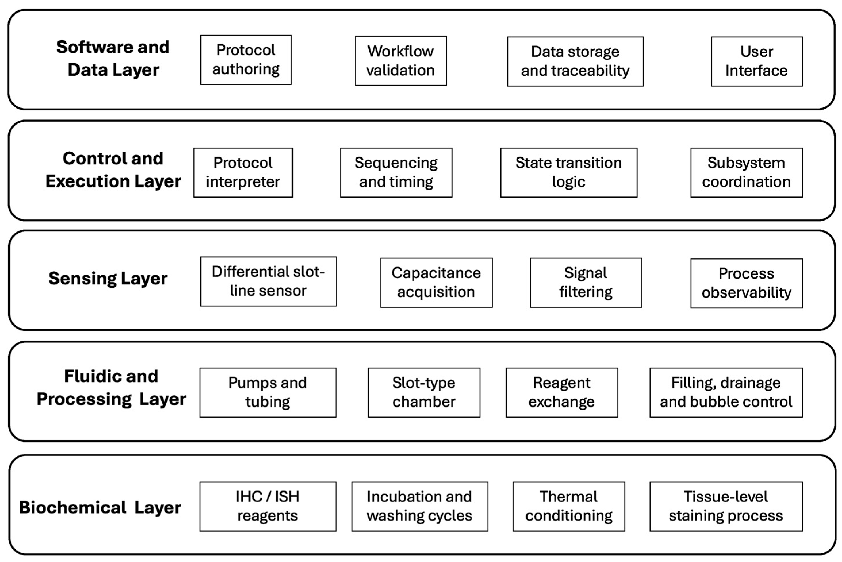
Based on the formal model introduced in the previous subsection, the proposed platform is implemented as a layered cyber-physical architecture comprising five functional layers:
S = H , F , S , C , D
where H denotes the hardware layer, F the fluidic processing layer, S the sensing layer, C the control and execution layer, and D the software and data layer.
In this work, the term cyber-physical architecture denotes a layered system in which physical reagent-handling processes are directly coupled with digital protocol execution through sensing, control, and software-based state representation. The architecture is cyber-physical because physical events are not only executed by hardware, but are also observed, interpreted, and used within the digital control logic to govern subsequent process steps.
Unlike conventional autostainers, in which reagent handling, process logic, and user interaction are tightly embedded into a proprietary implementation, this architecture separates physical execution, process observation, and decision logic while preserving their coupling through defined interfaces. The resulting organization is visualized in Figure 1, which represents the platform not as a hierarchical decomposition of components but as an operational cyber-physical loop: commands and actuation propagate downward from protocol definition to physical execution, while observation and process-state information propagate upward from the physical domain to the digital domain.

2.3.1. Biochemical Layer

The biochemical layer defines the domain-specific processing logic of tissue staining, encompassing the ordered sequence of reagent interactions with the specimen: sample wetting, blocking, primary and secondary reagent application, washing, amplification, chromogenic or fluorescent development, and optional ISH stages. Architecturally, this layer is the source of process requirements—reagent cycle count and ordering, incubation durations, temperature sensitivity, and clean-exchange constraints—that propagate downward into the physical and control structure of the platform. Critically, biochemical logic is not hard-coded into the instrument hardware; instead, it is represented through executable protocol definitions, allowing the same physical platform to support different classes of staining procedures without mechanical redesign.

2.3.2. Fluidic Processing Layer

The fluidic processing layer is responsible for the controlled transport, distribution, exchange, and evacuation of reagents. It comprises reservoirs, tubing, pumps, flow channels, and the slot-type microfluidic chamber, which enables low-volume reagent delivery directly over the specimen surface under geometrically constrained conditions. This layer translates protocol-level commands into physical reagent motion and is therefore central to process stability and reagent efficiency. Its behavior is governed by flow rate, feed direction, chamber orientation, and auxiliary actuation conditions such as vibration—the variables that define the operational stability domain W introduced in Section 2.2. The layer is not treated as a passive transport medium but as an actively controlled subsystem whose dynamic behavior must remain compatible with protocol timing and sensing feedback.

2.3.3. Sensing Layer

The sensing layer provides process observability by converting otherwise hidden physical events into measurable signals suitable for verification, monitoring, and control. In the proposed platform, this function is realized through a differential capacitive slot-line structure that detects the presence of liquid in the microtube network. Capacitive sensing was selected because it is insensitive to optical transparency and ambient illumination—practical limitations of optical and acoustic methods in compact microfluidic environments. In the formal framework of Section 2.2, the sensing layer contributes the observation vector y ( t ) , which the control layer uses to evaluate step completion, detect transport deviations, and, in future extensions, trigger corrective actions. Sensing is therefore not an auxiliary measurement accessory but a constitutive element of the cyber-physical execution loop.

2.3.4. Control and Execution Layer

The control and execution layer coordinates all active platform operations by mapping protocol definitions onto synchronized physical action sequences—pumping, timing, heating, cooling, signal acquisition, and state switching. In terms of the formal model, this layer implements the transition operator
x ( t k + 1 ) = Φ { x t k , u t k , y t k }
generating control actions u ( t k ) , interpreting sensing signals y ( t k ) , and enforcing transition conditions between successive execution states. A defining architectural feature of this layer is that it supports protocol-driven rather than hardware-driven execution: process logic can be modified at the protocol level without restructuring the physical subsystem, provided the required hardware capabilities are present. This separation is essential for multiplex IHC and ISH workflows, where procedural diversity and iterative reconfiguration are inherent to experimental practice.

2.3.5. Software and Data Layer

The software and data layer provides the user-facing and information-centric infrastructure of the system, including protocol authoring and editing, process parameter management, execution scheduling, data logging, event history storage, and operator interaction. It represents protocols in structured, machine-interpretable form, validates their internal consistency before execution, and transmits directives to the control layer at runtime. The stored operational history of each run enables quality assessment, repeatability analysis, and future linkage with analytical modules. The layer is designed for extensibility: the platform is conceived as an open ecosystem rather than a single-purpose instrument, and the software infrastructure is intended to accommodate future integration of computer vision modules, remote process supervision, and cloud-based data services.

2.3.6. Inter-Layer Interaction

Although functionally distinct, the five layers operate as a closed cyber-physical loop. Biochemical objectives defined in the uppermost layer are realized through the fluidic layer, observed through the sensing layer, coordinated through the control layer, and managed through the software layer. This dual-flow structure included downward actuation and upward observation, ensures that protocol execution remains continuously grounded in measurable physical behavior and that deviations can, in principle, be incorporated into adaptive control strategies.
The layered organization yields three system-level advantages relevant to multiplex staining applications:
  • Modularity ensures that functional concerns are isolated without being operationally disconnected, allowing individual layers to be upgraded independently.
  • Scalability allows additional chambers, sensors, or analytical modules to be incorporated without redefining the full system logic.
  • Flexibility enables staining workflows to be modified at the protocol and software level while the physical hardware remains unchanged.
Together, these properties distinguish the proposed platform from monolithic autostainer designs and establish an architectural basis for future extensions toward sensing-informed adaptive execution and broader digital integration. The following subsections describe the physical implementation and experimental configuration of the fluidic and sensing layers in detail.

2.4. Fluidic Subsystem Design and Experimental Setup

The fluidic subsystem was designed as the physical layer responsible for reagent transport, chamber filling, exchange, and evacuation during automated staining cycles. Its configuration was developed to support low-volume operation, repeated reagent replacement, and controlled chamber filling under different geometric and flow conditions.

2.4.1. Chamber Architecture

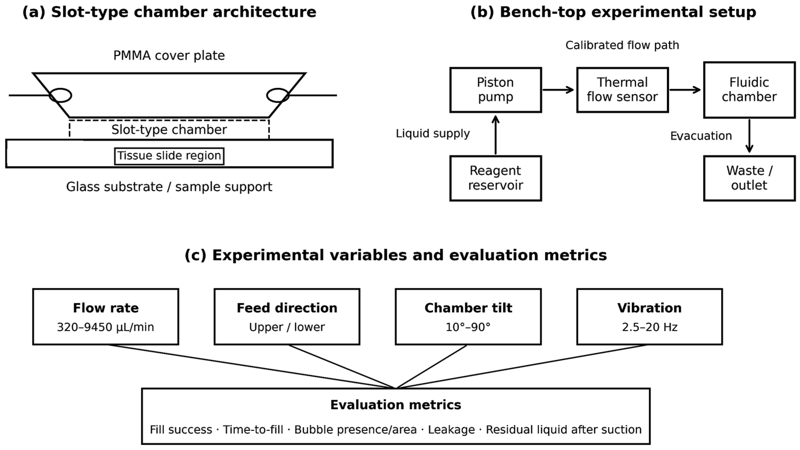
A slot-type microfluidic chamber was used as the central reaction unit. The chamber was formed by a PMMA cover plate bonded to a glass substrate and connected to inlet and outlet tubing. The design allowed operation in both upper-feed and lower-feed configurations, as well as controlled variation in chamber tilt angle.

2.4.2. Flow Generation and Calibration Setup

Fluid transport was driven by a piston pump. To relate pump setpoints to actual volumetric flow, calibration measurements were performed using a Sensirion SLF3S-0600F thermal mass-flow sensor (Sensirion AG, Laubisruetistrasse 50, 8712 Stäfa, Switzerland). The calibrated system was then used in chamber-filling experiments over a range of discrete flow conditions.

2.4.3. Fluids and Operating Conditions

Water was used for hydraulic calibration. Functional experiments were carried out using PBS (pH 7.4) with 0.05% Tween-20. The nominal chamber-filling volume was approximately 250–300 µL. Experiments were conducted under controlled laboratory conditions.
No biological tissue samples were used in the experimental validation reported in the present study. The fluidic and sensing experiments were performed at the subsystem level using test liquids and chamber-level configurations intended to reproduce the physical conditions of reagent transport relevant to future multiplex IHC/ISH operation. The tissue slide region shown in the chamber schematic represents the intended application geometry of the platform rather than a biological specimen source used in the present experiments.

2.4.4. Experimental Variables

The experimental design included variation in four principal parameters: flow rate, feed direction, chamber tilt angle, and vibration frequency. Feed-direction experiments were performed at a fixed angle of 45°, angle-screening tests were carried out between 10° and 90°, and vibration tests were conducted at frequencies between 2.5 and 20 Hz.

2.4.5. Evaluation Metrics

The performance of the fluidic subsystem was assessed using the following metrics: fill success, time-to-fill, bubble presence and relative area, leakage, and residual liquid after suction. These measures were used to characterize chamber-filling stability and reagent-exchange quality under different operating conditions.
The overall configuration of the fluidic subsystem, including the slot-type chamber geometry, the calibrated bench-top flow arrangement, and the principal experimental variables used for chamber-level evaluation, is summarized in Figure 2. This figure provides the methodological context for the fluidic experiments reported in Section 3 by linking the physical chamber design, the flow-control setup, and the selected performance metrics within a single schematic representation.
Figure 2 should be interpreted as the methodological realization of the fluidic processing layer introduced in the architectural model. Figure 2a defines the physical reaction domain in which reagent exchange takes place, including the slot-type chamber geometry and the inlet/outlet arrangement governing liquid access to the specimen region. Figure 2b represents the bench-top implementation used to generate, calibrate, and route liquid flow through the chamber, thereby translating protocol-level liquid-handling commands into experimentally controllable physical processes. Figure 2c summarizes the principal operating variables and evaluation metrics used to characterize chamber behavior, linking the experimental design to the stability-related criteria introduced in the mathematical framework. Taken together, these three views show that the fluidic subsystem is not treated merely as a transport path, but as an experimentally structured execution layer whose geometry, actuation conditions, and performance indicators define the practical domain of reagent exchange in the proposed platform.

2.5. Capacitive Sensing Subsystem

The capacitive sensing subsystem was designed for non-invasive detection of small liquid volumes inside plastic microtubes with inner diameters below 1 mm, providing process-relevant information for monitored protocol execution. Capacitive sensing was selected over optical and ultrasonic alternatives because it relies on changes in the dielectric properties of the medium in the sensing region and therefore does not require optical transparency or line-of-sight access, both practically limiting constraints in compact fluidic networks integrated into the staining platform hardware.

2.5.1. Slot-Line Sensing Structure and Differential Configuration

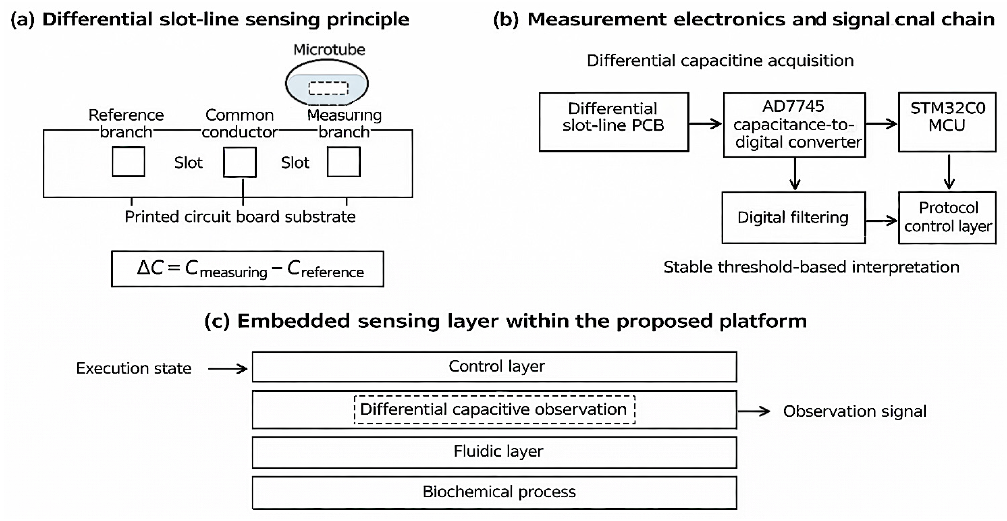
The sensing element was implemented as a slot-line structure fabricated on a printed circuit board, with the microtube positioned over the sensing region so that changes in the dielectric state of the tube environment affect the effective capacitance of the structure. To suppress parasitic effects and environmental disturbances, the subsystem was arranged in differential form: the board contained two slot lines sharing a common central conductor, with one branch serving as the reference element and the other as the measuring element. Shield conductors connected to common ground were incorporated into the layout to reduce stray electrostatic coupling. This configuration converts liquid-induced capacitance changes into a relative measurement between the two branches rather than an absolute single-channel value.

2.5.2. Measurement Electronics and Signal Preprocessing

The differential capacitive signal was digitized using an AD7745 capacitance-to-digital converter configured in differential mode (STMicroelectronics International N.V.39, Chemin du Champ-des-Filles 1228 Plan-les-Ouates Geneva, Switzerland), selected for its high resolution appropriate to the femtofarad-scale changes expected from micro-scale liquid detection. An STM32C0 microcontroller was used to configure the converter, preprocess digital data, and communicate with the higher-level control environment. Signal preprocessing was implemented as a first-order low-pass IIR filter in the form of an exponential moving average, smoothing the raw converter output before threshold-based liquid-presence interpretation.

2.5.3. Prototype Implementation

A prototype sensing board was fabricated using the differential slot-line configuration described above. A dedicated mounting fixture ensured reproducible microtube positioning over the measuring branch. The printed circuit board surface outside the active conductors was protected by a solder mask to limit uneven moisture absorption by the FR4 substrate, reducing environmental influence on the dielectric properties of the sensing region.
The overall concept of the capacitive sensing subsystem includes the differential slot-line sensing principle, the embedded measurement chain and its placement within the proposed architecture as the observation interface between the fluidic and control layers (Figure 3).
It should be noted that the proposed capacitive sensing subsystem does not directly measure the liquid state inside the staining chamber itself. Instead, it detects liquid presence in selected microtube segments that belong to the reagent-transport path leading to and from the chamber. Accordingly, the sensing layer provides an indirect observation of chamber-relevant process events, such as reagent arrival, line occupancy, or drainage progression, rather than a direct measurement of chamber-filling uniformity, local bubble distribution, or residual liquid inside the reaction zone. In the present architecture, the reliability of this indirect monitoring depends on the spatial placement of sensing points relative to the chamber, the reproducibility of transport timing, and the control logic used to interpret signal sequences. In this sense, reliable chamber-state inference is expected not from any single sensor reading alone, but from coordinated interpretation of sensor location, protocol step timing, and flow-direction logic within the overall execution framework.

2.6. Protocol Control and Software Representation

The protocol control and software layer provides the digital execution environment of the proposed architecture. Its role is to translate biochemical workflows into structured machine-executable procedures and to coordinate the interaction between the fluidic, sensing, and hardware subsystems during automated operation. In contrast to fixed-function autostainer logic, the proposed approach is conceived as a protocol-driven framework capable of supporting both standardized and custom staining procedures, including multiplex IHC and ISH workflows.

2.6.1. Protocol Representation

A staining workflow is represented as a structured protocol composed of discrete operational steps, each corresponding to an elementary action such as reagent injection, incubation, washing, thermal conditioning, or drainage. At the conceptual level, the protocol is modeled as a directed execution structure in which valid transitions are explicitly defined between successive states, enabling the system to distinguish between the semantic layer of the staining workflow and the physical layer of its realization. Each step is associated with a parameter tuple specifying operation type, target reagent identity, execution duration, flow-related settings, optional temperature conditions and completion criteria—making the protocol a parameterized executable object rather than a simple ordered list of instructions. This representation supports both linear and iterative execution logic, which is essential for multiplex procedures involving repeated reagent cycles, and allows different staining procedures to be executed on the same hardware through software-level reconfiguration.

2.6.2. Execution and Validation

Once defined, a protocol is interpreted by the control layer as an executable process specification. The execution engine dispatches coordinated control actions to the pump, chamber-handling components, thermal elements, and sensing subsystem in accordance with the currently active step and its parameters. Although the present study does not yet implement a fully adaptive closed-loop staining strategy, the software architecture was formulated to support monitored execution in which signals from the sensing layer may be incorporated into state verification and future conditional branching, corresponding, in terms of the formal framework of Section 2.2, to the use of observation signals y ( t ) within the transition operator Φ . A core requirement of this execution model is pre-execution validation of protocol structure, including verification of admissible step ordering, parameter completeness, and compatibility between requested operations and available subsystem capabilities. This reduces operator-dependent configuration errors in research-oriented settings where nonstandard workflows are common.

2.6.3. Data Handling and Extensibility

The software layer supports persistent storage of protocol definitions, process parameters, and execution records, enabling traceability of runs, comparison of repeated executions, and future linkage between process history and staining outcome assessment. This infrastructure also provides the foundation for integration of future modules, including computer vision, remote process supervision, and distributed data services, consistent with the ecosystem-oriented design intent of the proposed architecture.

3. Results

3.1. Flow Calibration and Setpoint-to-Flow Mapping

The first stage of the experimental evaluation was aimed at establishing the relationship between pump control setpoint and average volumetric flow in the reagent transport line. Since the fluidic subsystem was driven by a piston pump controlled through internal setpoints rather than direct flow-rate input, this calibration was necessary to provide an interpretable operational basis for subsequent chamber-filling experiments. Flow measurements were performed using a Sensirion SLF3S-0600F thermal mass-flow sensor, and the available pump range was divided into 20 setpoints for characterization.
The measured results showed that average flow increased monotonically with increasing pump setpoint. In the lower part of the tested range, the rise was close to linear, while at higher settings the slope became steeper. In particular, the average flow reached approximately 3150 µL/min at setpoint 10 and approximately 6300 µL/min at setpoint 20. Because the nominal range of the flow sensor is approximately 3600 µL/min, the highest measurements should be interpreted with caution; however, the overall trend remained sufficiently clear for practical calibration purposes. The resulting mapping therefore provided a usable setpoint-to-flow relationship for the chamber-level tests reported in the following subsections.
From an operational perspective, this calibration also allowed estimation of the practical filling capacity of the proposed platform. Considering a chamber and inflow volume of approximately 250 µL, a mid-range operating point around setpoint 8, corresponding to approximately 2600 µL/min, would support filling of about five parallel chambers within roughly 30 s. This result is significant because it indicates that the fluidic subsystem can provide reagent delivery speeds compatible with multi-chamber automated staining workflows without requiring operation at the highest and potentially less stable flow settings.
Overall, the calibration results confirm that the pump-controlled fluidic subsystem provides predictable and practically usable flow regulation across the tested range. This calibration serves as the reference basis for interpreting the chamber-filling dynamics, bubble formation behavior, and preferred operating windows described in the following results.

3.2. Effect of Feed Direction on Chamber-Filling Dynamics

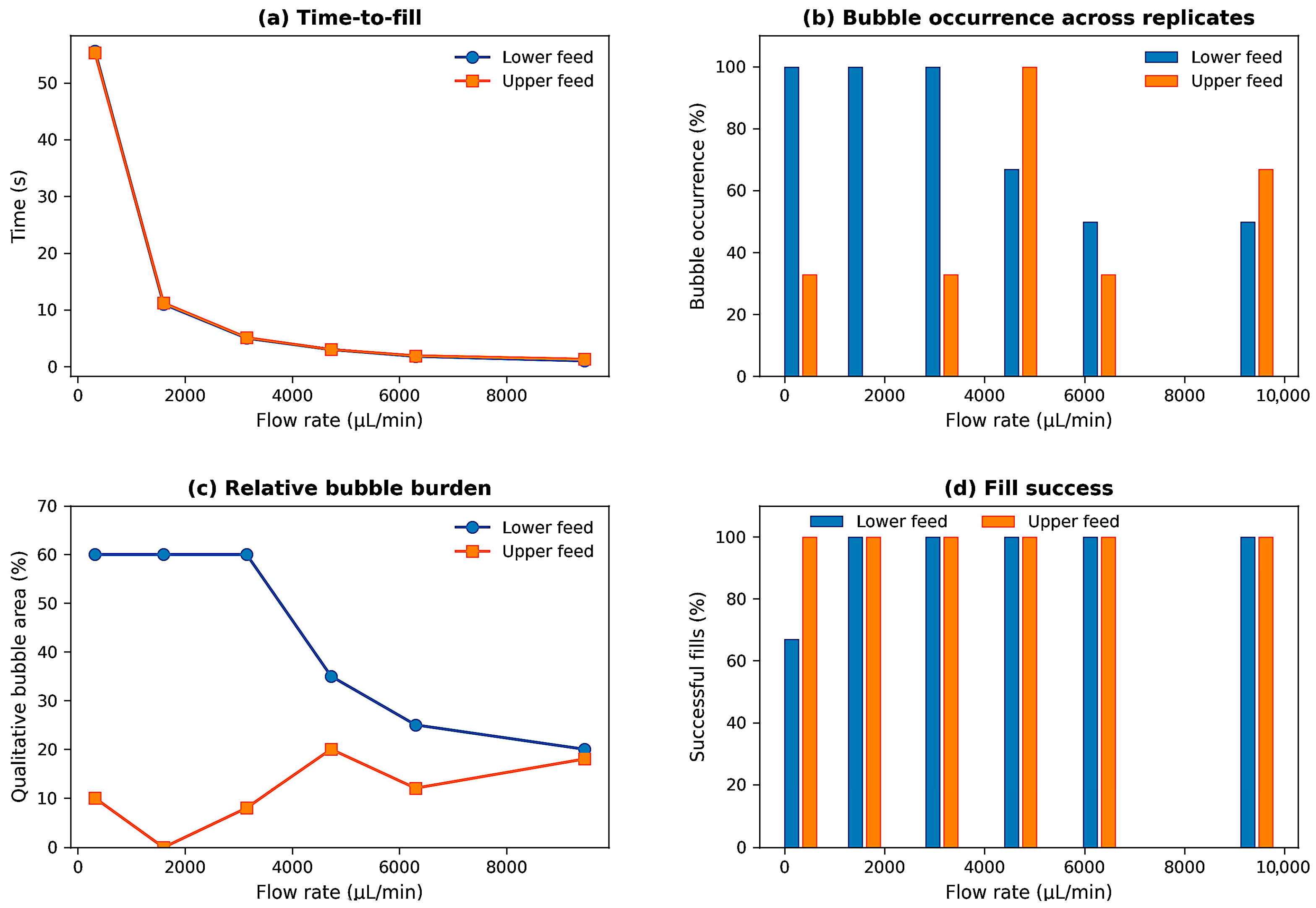
To evaluate the influence of reagent supply direction on chamber-filling behavior, comparative experiments were performed using lower-feed and upper-feed configurations at a fixed chamber tilt angle of 45°. For each configuration, the chamber was tested across six flow conditions between 320 and 9450 µL/min, and the outcomes were assessed in terms of fill success, time-to-fill, bubble occurrence, and leakage. This comparison was introduced to determine which feed mode provides the most suitable balance between rapid filling and fluidic stability in the slot-type chamber architecture.
The comparative outcomes of lower-feed and upper-feed operation across the tested flow range are summarized in Figure 4. The figure integrates the principal chamber-level performance indicators, including filling time, bubble occurrence, qualitative bubble burden, and fill success, thereby providing the experimental basis for identifying the preferred feed configuration for the proposed platform.
In the lower-feed configuration, chamber filling was successful in 17 of 18 trials, and no leakage was observed. However, bubble formation was frequent and occurred in 14 of 18 cases, corresponding to approximately 77% of all attempts. At the lower end of the tested flow range, bubbles were typically larger, with some cases showing bubble occupation of a substantial fraction of the chamber area. As the flow rate increased, time-to-fill decreased predictably, but the bubble pattern changed from fewer large bubbles to more fragmented foam-like structures. Thus, although lower-feed operation provided generally successful filling, it was associated with a substantially higher frequency of bubble occurrence and a greater bubble burden than upper-feed operation under the tested conditions.
In the upper-feed configuration, all tested runs were completed without leakage and with similarly short filling times at comparable flow conditions. Bubble formation was observed less frequently than in the lower-feed case, occurring in 8 of 18 runs, or about 44% of all trials. The most favorable behavior was observed at moderate flow conditions, particularly around 1600 µL/min, where no bubble formation was reported in the tested replicates. At higher flow rates, bubbles reappeared more often, indicating that excessive inflow velocity may still destabilize the advancing liquid interface even in the upper-feed configuration. Nevertheless, the overall bubble burden remained lower than in the lower-feed case.
The filling times in both configurations decreased strongly with increasing flow rate, from approximately 55 s at the lowest tested condition to around 1–1.3 s at the highest. This indicates that feed direction did not fundamentally alter the general flow-rate dependence of filling speed. Instead, its primary influence was observed in the quality of filling, particularly in relation to bubble suppression. In this respect, upper feed provided a more favorable compromise between fast chamber filling and reduced bubble occurrence.
From the standpoint of system operation, these results indicate that feed direction is a significant design variable for chamber-level stability. While both modes can complete chamber filling, upper-feed operation is preferable for the proposed staining platform because it reduces bubble-related disturbances without sacrificing throughput. In combination with the calibrated mid-range flow regime established in Section 3.1, the upper-feed configuration defines the more promising basis for stable reagent exchange in the subsequent analysis.

3.3. Effect of Chamber Tilt Angle on Fluidic Stability and Drainage

To identify a practically suitable chamber geometry for automated staining cycles, the influence of chamber tilt angle on filling quality, bubble formation, leakage, and post-suction drainage was evaluated under fixed upper-feed operation. In these experiments, the reagent flow rate was maintained at 1600 µL/min, while the chamber angle was varied from 10° to 90° in 10° increments. The purpose of this analysis was to determine the angular range in which the chamber could be filled reproducibly with minimal fluidic disturbance and acceptable evacuation performance.
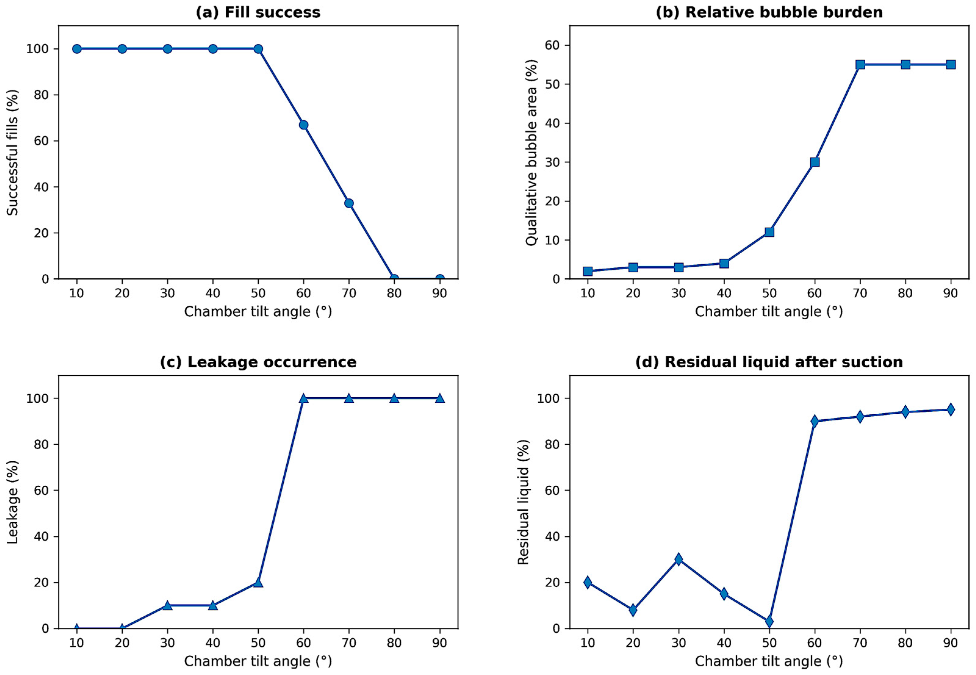
The angle-dependent behavior of the chamber is summarized in Figure 5. The figure integrates the principal fluidic stability indicators, including fill success, qualitative bubble burden, leakage occurrence, and residual liquid after suction, and thereby provides the experimental basis for identifying the practically admissible chamber-orientation range for the proposed platform.
At low chamber angles, from 10° to 40°, all fills were successful and generally exhibited high filling quality. Bubble formation remained minimal, typically not exceeding a small fraction of the chamber area, and leakage under the cover glass was observed only occasionally. Drainage after suction was more variable: some trials showed nearly complete evacuation, whereas others retained a moderate residual fraction of liquid. Nevertheless, the overall fluidic behavior in this angular range remained stable and compatible with routine chamber operation.
At 50°, the chamber still remained operational, but the quality of filling began to decline relative to the low-angle regime. In particular, bubble formation became more pronounced, indicating that the interface dynamics were becoming less stable. At the same time, this angle produced the most favorable drainage behavior, with the lowest residual liquid after suction, approximately 3% in the reported experiments. This suggests that the 50° configuration represents a transitional regime in which the chamber benefits from improved gravitational drainage, although at the cost of reduced filling stability.
A marked deterioration was observed at higher angles, from 60° to 90°. In this regime, filling became unreliable, the bubble area increased substantially, leakage became consistent, and suction was no longer effective in removing the chamber contents. Residual liquid after evacuation reached approximately 90–95%, indicating that the chamber could no longer support clean reagent exchange under these conditions. Such behavior is incompatible with multiplex staining workflows, where repeated filling and drainage steps must be executed without large carryover between cycles.
Taken together, these results indicate that chamber angle is a critical determinant of fluidic stability in the proposed slot-type architecture. The range between 10° and 40° provides the most stable filling conditions, combining successful fills with low bubble incidence and infrequent leakage. The angle of 50° improves drainage performance but already shows signs of degraded fill quality. Angles of 60° and above fall outside the practical operating range because they lead to unstable interfacial behavior, persistent leakage, and ineffective chamber evacuation. Accordingly, the experimentally supported working geometry for the proposed platform is defined primarily by low-angle operation, with 10–40° representing the most robust region for routine reagent exchange.

3.4. Vibration-Assisted Bubble Mobilization: Preliminary Observations

As a supplementary investigation, the effect of controlled mechanical excitation on bubble mobilization was assessed at a chamber tilt angle of 45° across five vibration frequencies (2.5, 5, 10, 15, and 20 Hz), with a preformed bubble occupying approximately 20% of the chamber area introduced into the lower chamber region prior to each trial (n = 3 per frequency). The small number of replicates per condition means these results should be interpreted as preliminary observations rather than statistically conclusive findings; a dedicated study with larger sample sizes is required to characterize the effect quantitatively.
At frequencies of 2.5 and 5 Hz, no consistent change in bubble position or morphology was detected across replicates. At 10 Hz, bubble coalescence and lateral exit were observed in one of three trials, but the response was not reproduced in the remaining replicates. The most consistent responses were obtained at 15 and 20 Hz, where upper-region bubble release was observed in two of three trials at each frequency; the large lower bubble remained pinned in place under all tested conditions. The spatially selective character of the response—upper bubbles mobilized, lower bubble unaffected—suggests that vibration-induced clearing is governed by local retention forces that differ substantially between chamber regions.
Taken together, these observations indicate that mechanical excitation at higher frequencies may offer a supplementary means of reducing upper-surface bubble accumulation, but does not constitute a reliable primary degassing strategy, particularly for bubbles trapped in the lower chamber. On this basis, vibration is not incorporated as a principal operating variable in the integrated platform window defined in Section 3.7.

3.5. Capacitance Characteristics of the Slot-Line Sensing Element

To evaluate the feasibility of using a slot-line structure as the sensing element of the capacitive subsystem, its capacitance characteristics were investigated both analytically and experimentally. This study considered several slot-width configurations and examined how the effective capacitance of the structure changed when a microtube filled with different media was positioned above the sensing region. The purpose of this analysis was to determine whether the slot-line geometry provides capacitance levels and liquid-induced variations suitable for practical microfluidic detection in the proposed platform.
The slot line was modeled as a printed-circuit-board structure whose capacitance can be represented as the sum of two partial capacitances associated with the air region and the dielectric substrate. Using the partial-capacitance method and conformal transformation-based expressions, the capacitance per unit length and the total capacitance were calculated for slot widths of 0.5, 1.0, and 1.5 mm. For a slot-line length of 30 mm, the calculated total capacitance values were approximately 1.097 pF, 0.867 pF, and 0.745 pF, respectively. Experimental measurements performed on fabricated structures yielded corresponding values of approximately 1.093 pF, 0.961 pF, and 0.843 pF. The results showed close agreement between calculation and experiment for the 0.5 mm configuration, whereas the wider slots exhibited larger deviations. This indicates that the narrowest tested slot geometry provides the most consistent basis for practical sensor implementation.
Based on these results, the slot line with a width s = 0.5 mm and length L = 30 mm was selected for further investigation. The measured capacitance of this structure exceeded 1 pF even before the introduction of the microtube, which is advantageous from the standpoint of differential measurement because it places the sensing element in a range that is readily accessible to the chosen capacitance-to-digital conversion electronics. At the same time, the presence of a microtube above the line produced additional capacitance changes that were sufficiently large to be detected experimentally.
To characterize sensitivity to tube filling conditions, the capacitance of the selected slot-line structure was measured with a microtube positioned over it and filled with air, xylene, or water. The measured capacitance values were approximately 1.214 pF for air, 1.246 pF for xylene, and 1.324 pF for water. Relative to the baseline slot-line capacitance, these correspond to capacitance increases of about 0.121 pF, 0.153 pF, and 0.231 pF, respectively. These results show that the sensing element responds not only to the presence of the microtube itself, but also to the dielectric properties of the medium inside it. In particular, water produced the largest capacitance increase, whereas air and xylene produced smaller but still measurable changes.
From a sensing perspective, these results demonstrate two important properties of the slot-line element. First, the structure exhibits stable capacitance values in the picofarad range, which supports integration into a practical differential measurement circuit. Second, the microtube environment induces capacitance variations in the range of tens to hundreds of femtofarads, which is sufficient to justify the use of a high-resolution capacitive readout architecture. Thus, the slot-line element provides an experimentally supported basis for the capacitive sensing subsystem proposed in Section 2.

3.6. Differential Sensor Response and Minimum Detectable Liquid Volume

Following characterization of the slot-line sensing element, the differential sensing configuration was evaluated in order to determine its practical response to liquid introduction into the microtube and to estimate the minimum detectable liquid volume. The experiments were performed using the prototype sensor board described in Section 2.5, with the microtube positioned over the measuring branch of the differential slot-line structure. Liquid was introduced into the tube in controlled increments, and the corresponding differential capacitance response was obtained from the digitized and filtered sensor output.
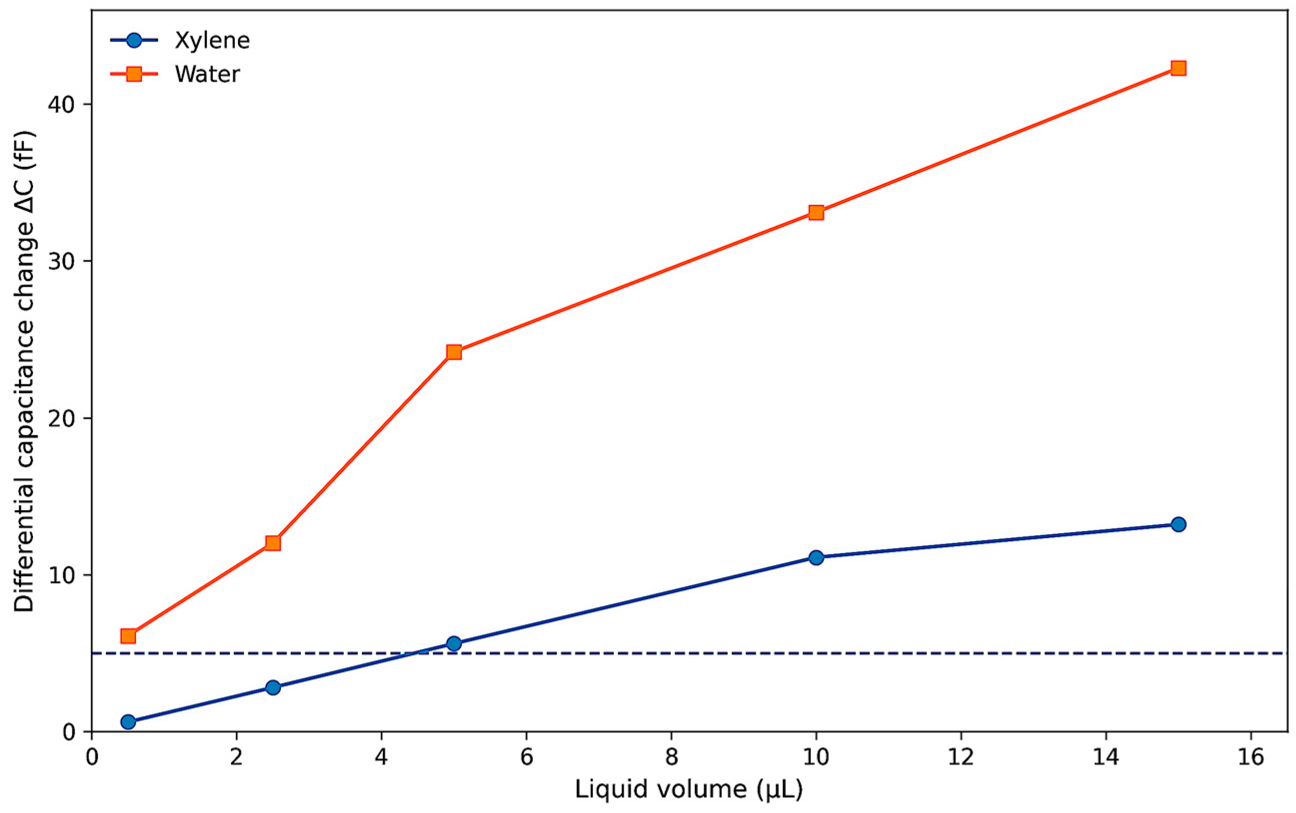
The volume-dependent differential response of the prototype sensor is summarized in Figure 6. The figure visualizes the measured capacitance change for two representative liquids with different dielectric properties and highlights the practical detection threshold used for interpreting micro-scale filling events within the proposed sensing architecture.
Differential capacitance change Δ C measured for xylene and water as a function of injected liquid volume in the microtube positioned over the measuring branch of the slot-line sensor. The dashed horizontal line indicates the practical detection threshold of approximately 5 fF after digital filtering.
The results showed that the sensor produced a measurable response even for very small injected volumes. For xylene, the differential capacitance change was approximately 0.6 fF at 0.5 µL, 2.8 fF at 2.5 µL, 5.6 fF at 5 µL, 11.1 fF at 10 µL, and 13.2 fF at 15 µL. For water, the corresponding values were substantially higher: approximately 6.1 fF at 0.5 µL, 12.0 fF at 2.5 µL, 24.2 fF at 5 µL, 33.1 fF at 10 µL, and 42.3 fF at 15 µL. These data confirm that the differential sensor response increases with liquid volume and that the response magnitude depends strongly on the dielectric properties of the transported medium.
A notable result is that the prototype was able to detect liquid volumes well below 10 µL, which was the target scale specified for the sensing subsystem. In particular, the experiments demonstrated detectable signal changes already at 0.5 µL, corresponding to less than 5% of the total volume of the microtube segment positioned above the sensing region. This finding indicates that the proposed sensing subsystem is compatible with micro-scale reagent transport monitoring in the fluidic network of the automated staining platform.
The results also show a clear distinction between low-permittivity and high-permittivity liquids. Water generated significantly higher differential capacitance changes than xylene for all tested volumes, which is consistent with the dielectric sensing principle underlying the slot-line configuration. However, even for xylene, the differential response remained measurable in the femtofarad range, demonstrating that the sensing subsystem is not limited to only highly polar liquids. This is important for the intended application, since pathological workflows may involve reagents with substantially different physical properties.
Signal conditioning also played an important role in practical detection. The use of exponential moving averaging allowed the liquid-detection threshold to be reduced to approximately 5 fF while maintaining sufficient stability of the interpreted sensor output. This threshold level is particularly relevant for the lower-volume measurements and supports the feasibility of threshold-based event detection in the presence of noise and small measurement fluctuations. In practical terms, the filtered differential architecture enables the sensing subsystem to support reliable monitoring of reagent presence in microtubes even when the transported volumes are very small.
Taken together, these results demonstrate that the differential slot-line sensor provides a physically meaningful and operationally useful response to microtube filling. The subsystem can detect sub-10 µL liquid volumes, distinguish between media with different dielectric properties, and provide stable measurement output when combined with digital filtering. Therefore, the sensing layer is not only theoretically compatible with the proposed staining platform but experimentally capable of supporting micro-scale transport observation within the broader cyber-physical architecture.

3.7. Integrated Operational Window of the Proposed Platform

The preceding results make it possible to define an integrated operational window for the proposed platform by combining the experimentally observed constraints of the fluidic subsystem with the demonstrated feasibility of the sensing subsystem. Rather than treating chamber filling, bubble behavior, drainage, and liquid detection as isolated phenomena, this subsection interprets them jointly as system-level conditions that determine whether the proposed cyber-physical staining platform can operate in a stable and practically useful manner.
From the fluidic perspective, three factors were found to be especially important: flow regime, feed direction, and chamber orientation. The pump calibration established a usable mapping between internal setpoint and volumetric flow, which provided the reference basis for controlled chamber-filling experiments. Within this calibrated range, moderate operating conditions were shown to support practically relevant filling times without requiring operation at the most extreme flow settings. Feed-direction experiments further demonstrated that upper-feed operation produced a more favorable balance between filling speed and filling quality than lower-feed operation, primarily because it reduced the frequency and severity of bubble-related disturbances while preserving rapid chamber filling. Angle-screening experiments showed that low-angle operation, particularly within the range of 10–40°, provided the most stable filling behavior, whereas higher angles progressively increased bubble formation, leakage, and drainage failure. Together, these results define the fluidically preferred regime of the platform as a combination of calibrated moderate flow, upper-feed delivery, and low-angle chamber positioning.
The vibration experiments complement this picture by showing that controlled mechanical excitation may improve fluidic behavior under selected conditions, but only as an auxiliary mechanism. Frequencies of 15–20 Hz facilitated the release of bubbles located in the upper chamber region, whereas lower-frequency vibration produced little or no effect, and bottom-trapped bubbles remained largely unaffected under the tested conditions. This indicates that vibration may be incorporated as an optional stabilization aid, particularly for clearing residual upper-surface bubbles, but it does not redefine the primary operating window established by geometry and feed direction. The stable operating regime of the platform therefore remains governed mainly by chamber orientation and flow configuration, with vibration serving as a secondary enhancement rather than a primary design variable.
From the sensing perspective, the results confirmed that the slot-line capacitive subsystem is compatible with this fluidic operating regime. The selected slot-line geometry produced stable capacitance values in the picofarad range and measurable capacitance shifts when a microtube filled with different media was positioned above the sensing element. In differential mode, the prototype sensor responded detectably to liquid volumes well below 10 µL and maintained interpretable output through digital filtering, with a practical threshold on the order of 5 fF. This means that the platform does not merely admit stable reagent transport in the preferred fluidic regime; it also admits observation of transport-related events at the micro-scale, which is essential for the transition from purely open-loop execution to monitored execution.
Taken together, these findings support the conclusion that the proposed platform possesses an experimentally grounded operational window in which reagent exchange and process observation are jointly feasible. In practical terms, this window is characterized by: (i) calibrated moderate flow conditions, (ii) upper-feed chamber filling, (iii) low-angle chamber operation, typically within the 10–40° range, and (iv) optional high-frequency vibration only as a supplementary measure for selective bubble release. Within this regime, the fluidic subsystem provides sufficiently stable filling and evacuation behavior, while the sensing subsystem remains capable of detecting micro-scale liquid presence in the transport network.
This integrated interpretation is important because it elevates the experimental findings from component-level observations to a system-level result. The platform is not defined only by the existence of a workable chamber or a sensitive slot-line sensor in isolation. Instead, its practical value lies in the coexistence of a fluidically stable operating regime and a sensing mechanism capable of observing transport events within that regime. In this sense, the operational window identified here constitutes the first experimental validation of the proposed cyber-physical architecture as a coordinated staining platform rather than as a collection of independent modules.

4. Discussion

4.1. Architectural Significance of the Reported Results

The reported results are significant not only because they demonstrate the feasibility of individual technical components, but because they provide experimental support for the layered cyber-physical architecture proposed in this study. In many existing staining platforms, fluid handling, monitoring, and execution logic are implemented as tightly coupled instrument-specific functions. By contrast, the present work treats the staining platform as an integrated system composed of interacting fluidic, sensing, control, and protocol layers. The experiments reported in Section 3 show that this system-level representation is not merely conceptual: the fluidic layer admits a practically stable operating regime, and the sensing layer remains capable of observing micro-scale liquid transport within that regime. This coexistence of controllable execution and measurable process observability is the principal architectural result of this study.
From an architectural standpoint, the most important outcome is the confirmation of subsystem compatibility. The slot-type chamber does not function in isolation; its practical value depends on whether it can support repeatable filling, exchange, and evacuation under conditions that are suitable for automated protocol execution. Likewise, the differential capacitive sensor is not introduced as an independent measurement device, but as an observation mechanism that can be incorporated into the platform’s execution logic. The experimental results support this architectural coupling: the fluidic subsystem defines a feasible process domain, and the sensing subsystem provides the basis for monitoring physical events within that domain. This is precisely the condition required for a cyber-physical staining system to move beyond open-loop automation and toward monitored, and ultimately adaptive, execution.
A second architectural implication concerns modularity. The results suggest that the platform can be understood as a composable system in which experimentally validated layers may be extended without redefining the entire device logic. The fluidic layer can be optimized further in terms of chamber geometry, parallelization, or reagent routing, while the sensing layer can be expanded toward richer process-state detection. Because the control logic is represented at the protocol level rather than embedded into a rigid hardware sequence, these improvements can in principle be introduced within the same architectural framework. This distinguishes the proposed approach from monolithic autostainer designs, where extension often requires substantial redesign of the full instrument.
The reported findings also justify the decision to frame the platform as a cyber-physical system rather than as a collection of laboratory modules. In the mathematical formulation introduced in Section 2, the platform state evolves through interaction between physical transport processes, sensing-derived observations, and protocol-driven control actions. The experiments support this interpretation by showing that the relevant physical variables—such as chamber-filling quality, bubble presence, leakage, and liquid detection—are not independent engineering details, but state-defining features of the platform’s operational behavior. Accordingly, the architecture is validated not at the level of abstract decomposition alone, but at the level of experimentally observable subsystem interaction.
In this sense, the principal contribution of this study is architectural rather than component-specific. The slot-line sensor and the fluidic chamber are important, but their importance lies in the fact that together they establish the first experimentally grounded operating domain of the proposed platform. This transforms the architecture from a design hypothesis into a system concept with demonstrated physical feasibility, thereby providing a credible foundation for future expansion toward multi-chamber execution, sensing-informed protocol control, and integration with higher-level digital modules such as computer vision and remote supervision.
The formal framework introduced in Section 2.2 provides a useful interpretive lens for the reported results, even at the current stage of qualitative application. The experimentally identified operating window combining upper-feed delivery, calibrated moderate flow and low chamber angles, corresponds directly to the admissible domain W defined by the instability functional Ψ : the tested configurations that produced stable filling, low bubble incidence, and effective drainage can be understood as operating points satisfying Ψ ε , while the high-angle and lower-feed regimes that exhibited leakage, bubble accumulation, and drainage failure correspond to configurations outside this domain. Similarly, the sensing results establish the observational basis for the state transition operator Φ , which requires the observation vector y ( t ) to be defined before protocol-driven state transitions can be conditioned on physical process events. In this sense, the present study validates the two physical preconditions of the formal model (a bounded fluidic operating domain and a measurable observation layer) without yet quantifying the model parameters. Numerical determination of the weighting coefficients w i and empirical evaluation of Ψ across systematically varied operating conditions are identified as priorities for future experimental work.

4.2. Fluidic Stability as a System-Level Constraint

The results clearly show that fluidic stability is not a secondary implementation detail, but a system-level constraint that defines the feasible execution domain of the entire staining platform. In automated multiplex workflows, successful operation depends not only on the nominal sequence of reagent steps but on the ability of the chamber to realize these steps physically under repeatable and disturbance-limited conditions. Bubble formation, incomplete filling, leakage, and poor drainage are therefore not isolated imperfections; they are manifestations of instability that directly limit the reliability of protocol execution.
Among the tested variables, feed direction emerged as a particularly important determinant of filling quality. Although both lower-feed and upper-feed configurations could complete chamber filling across much of the tested range, upper-feed operation produced substantially fewer bubble-related disturbances while maintaining comparable filling times. This difference should be interpreted primarily as an experimentally observed effect of feed topology on filling quality rather than as direct proof of a single underlying mechanism. In the present study, the lower-feed configuration exhibited a higher frequency of bubble occurrence and a greater bubble burden than the upper-feed configuration under otherwise comparable conditions. More broadly, the microfluidics literature recognizes bubble formation, retention, and incomplete removal as common sources of flow instability, nonuniform wetting, and performance degradation in confined flow systems. Accordingly, our results support the practical conclusion that reagent-entry configuration is an important determinant of chamber-level fluidic stability, even though the precise local mechanisms of bubble trapping and release in the present slot-type geometry require further dedicated investigation. This result is important because it indicates that the topology of reagent entry into the chamber affects not only transport speed but also interfacial stability. For multiplex staining, where repeated exchange cycles are required, this distinction is critical: a configuration that fills rapidly but frequently traps air is less valuable than one that combines speed with stable chamber wetting. The observed advantage of upper feed therefore has direct architectural implications for chamber-level process design.
Chamber angle produced an equally important constraint. The experiments showed that low-angle operation, particularly within the 10–40° range, provided the most stable overall behavior, whereas higher angles progressively degraded filling quality and drainage reliability. The deterioration observed at angles of 60° and above is especially significant because it demonstrates that the chamber does not admit uniformly stable operation across all geometrically admissible configurations. In other words, the fluidic layer possesses an experimentally bounded operational region rather than unrestricted flexibility. This aligns closely with the mathematical concept of an operational stability domain introduced in Section 2.2: the chamber is practically usable only within a restricted subset of the parameter space defined by flow rate, orientation, and feed configuration.
The vibration experiments reinforce this interpretation. Mechanical excitation at higher frequencies could assist in the removal of certain upper-surface bubbles, but it did not eliminate all trapped gas and had little effect on bottom-pinned bubbles. This shows that auxiliary physical interventions may improve local behavior without redefining the primary stability constraints of the system. Put differently, vibration can extend or refine the operational regime, but it cannot compensate for an intrinsically unstable chamber geometry or an unfavorable feeding configuration. From a systems perspective, this is an important result because it prevents over-reliance on secondary correction mechanisms and places the primary design emphasis where it belongs: on chamber geometry, reagent-entry topology, and the base flow regime.
Another important implication is that fluidic stability conditions are inseparable from reproducibility. In conventional discussions of automated staining, reproducibility is often framed in terms of timing precision or reagent consistency. The present results show that reproducibility must also be interpreted physically: a protocol cannot be considered reproducible if one run produces clean chamber wetting and another produces trapped bubbles or substantial residual liquid after suction. The fluidic layer therefore defines a precondition for meaningful protocol repeatability. Stable biochemical execution is possible only if the reagent exchange itself is stable. This is particularly relevant for multiplex IHC and ISH workflows, where each subsequent cycle depends on the quality of the previous exchange and where residual liquid or trapped air may propagate error across the full protocol sequence.
For these reasons, fluidic stability should be regarded as one of the central system-level constraints of the proposed platform. It determines the admissible operating window, limits the reliability of protocol execution, and conditions the usefulness of higher-level architectural features such as sensing and software control. The practical value of the platform therefore depends not merely on having a chamber capable of filling but on having a chamber capable of filling reproducibly within a bounded and experimentally characterized regime. The identification of such a regime is one of the key contributions of the present study and forms the operational basis for any future transition toward adaptive closed-loop staining workflows.

4.3. Role of the Capacitive Sensing Layer in Process Observability

A key limitation of many automated staining platforms is that reagent transport is largely assumed rather than directly observed. In such systems, successful execution of a programmed workflow depends on the expectation that the commanded fluidic action has occurred as intended, even though the actual presence or absence of liquid in specific parts of the transport network is not explicitly verified. The capacitive sensing layer proposed in this study addresses this limitation by introducing process observability at the microfluidic level. Instead of treating reagent delivery as a hidden internal event, the platform gains the ability to convert local physical changes associated with microtube filling into measurable digital signals.
To place the proposed sensing layer in a more explicit state-of-the-art context, it is useful to compare it with optical and ultrasonic liquid-detection approaches along three practically relevant dimensions: sensitivity at the micro-scale, robustness to operating disturbances, and integration compatibility with compact staining hardware. In the present platform, the capacitive subsystem was designed for microtubes with inner diameters below 1 mm and for target detectable liquid volumes not exceeding 10 µL; experimentally, the differential slot-line sensor produced detectable responses already from 0.5 µL, while stable threshold-based interpretation was achieved at a practical threshold of approximately 5 fF after digital filtering. By comparison, optical sensing can be highly responsive in transparent and well-controlled conditions, but its effective use in compact reagent networks is constrained by tube transparency, liquid coloration, contamination or staining of the tube wall, and sensitivity to ambient light. Ultrasonic sensing is attractive because it does not require optical access, yet in small-diameter tubing, its implementation becomes more demanding due to miniaturization constraints, excitation-frequency requirements, and sensitivity to vibration and bubble-induced signal disturbance. In this sense, the main advantage of the present capacitive approach is not only its micro-scale sensitivity, but its favorable integration profile: the slot-line sensing element is embedded directly in the printed circuit board, does not require line-of-sight access, remains compatible with opaque or stained liquids, and can be incorporated into a differential measurement architecture suitable for monitored execution in a compact cyber-physical staining platform.
The practical position of the proposed sensing subsystem relative to optical and ultrasonic alternatives is summarized in Table 2. The comparison focuses on criteria that are especially relevant for compact multiplex IHC/ISH platforms.
From a systems perspective, this contribution is important because observability is a prerequisite for any transition from open-loop automation to monitored or adaptive execution. In the architectural framework introduced earlier, the sensing layer provides the observation vector through which the physical state of the fluidic subsystem can be represented in the control domain. The experimental results confirm that the slot-line sensing element exhibits stable capacitance in the picofarad range and measurable medium-dependent changes in the femtofarad range, while the differential measurement scheme and digital filtering provide a practical basis for threshold-based liquid detection. This means that transport events in the fluidic layer are not only physically occurring but also digitally interpretable.
The choice of capacitive sensing is also significant in relation to the physical constraints of compact staining devices. Optical sensing methods are often limited by tube transparency, liquid coloration, and ambient illumination, while ultrasonic approaches may be affected by geometric miniaturization, vibration, and bubble presence. The slot-line capacitive method avoids dependence on line-of-sight access and remains compatible with the tightly integrated microtube geometry of the proposed platform. In this respect, the sensing layer is not merely an added measurement feature, but a physically appropriate observation mechanism for a compact reagent-transport architecture. Its role becomes even more important when the platform is considered as a research-oriented system, where custom workflows, nonstandard reagents, and repeated protocol reconfiguration increase the value of direct transport-state verification.
At the same time, the present sensing concept has an important architectural limitation: it observes the transport state in the microtube network rather than the chamber interior directly. This means that the sensing layer can reliably indicate events such as reagent passage, liquid arrival, or incomplete line emptying, but it does not by itself guarantee direct knowledge of local chamber phenomena such as nonuniform filling, bubble trapping within the reaction area, or residual liquid distribution over the specimen surface. For this reason, the sensing layer should be interpreted as an indirect process-observation mechanism whose reliability depends on appropriate sensor placement and signal logic. In practical terms, this suggests two complementary strategies for future development: first, positioning sensing points at functionally critical locations, such as immediately upstream and downstream of the chamber, and second, using sequential signal interpretation within the protocol logic rather than isolated threshold crossings. Such an approach would allow chamber-state inference to be strengthened through event consistency, transport timing, and directional liquid-path validation, even when the chamber itself is not instrumented internally.
Another important aspect is that the sensing layer contributes not only to fault detection but also to architectural extensibility. Once transport events can be observed reliably, it becomes possible to define higher-level execution logic that responds to actual process state rather than relying exclusively on predefined timing. Although the present work does not yet implement a fully adaptive closed-loop staining strategy, the reported sensing results establish the technical precondition for such an extension. In practical terms, this means that future versions of the platform could use sensing output to validate reagent arrival, detect incomplete transport events, or trigger corrective actions within the protocol execution sequence. Thus, the capacitive sensing layer should be understood as the enabling interface between physical reagent motion and future intelligent control.

4.4. Comparison with Existing Automated Staining Approaches

The proposed platform differs from existing automated staining approaches in both structural philosophy and operational focus. Conventional commercial autostainers are generally designed as closed and highly integrated instruments optimized for robustness in predefined workflows. Their main strengths are mature hardware integration and procedural stability in standardized laboratory settings. However, these systems are frequently associated with high capital and operating costs, limited flexibility in protocol modification, and dependence on proprietary reagent ecosystems. In contrast, the platform proposed here is designed as a modular cyber-physical system in which protocol logic, fluidic execution, sensing, and future analytical extensions are treated as separable but coordinated layers. This gives priority not only to automation itself, but to adaptability and architectural extensibility.
Compared with existing microfluidic staining approaches, the present system also adopts a broader architectural perspective. Many microfluidic solutions reported in the literature focus on improving reagent efficiency, shortening diffusion paths, or accelerating exchange in a local chamber environment. While such studies are highly valuable, they are often centered on the chamber or fluidic device as an isolated engineering object. The results presented here retain the advantages of slide-scale microfluidic processing but place them within a system architecture that explicitly includes sensing and protocol-driven execution. The significance of this difference is that fluidic performance is not interpreted as an end in itself, but as one layer of a platform intended for monitored automated operation. The identified operating window therefore has architectural meaning beyond chamber hydrodynamics alone.
A similar distinction applies to sensing. Stand-alone capacitive sensing solutions have been reported for various microfluidic tasks, but they are often developed as independent detection devices rather than as embedded observation layers within a larger biomedical execution platform. In the present work, the slot-line differential sensor is valuable not simply because it can detect small liquid volumes, but because it is structurally integrated into the architecture of the staining system and interpreted as part of the control-observation loop. This moves the role of sensing from component-level measurement to system-level process observability. In this sense, the novelty of the proposed approach lies less in any single subsystem than in the experimentally supported compatibility of fluidic execution and sensing-based observation within one modular platform.
Therefore, when compared with existing automated staining approaches, the proposed platform occupies an intermediate but promising position. It does not yet claim the full clinical maturity of established commercial autostainers, nor does it reduce itself to a single microfluidic or sensing innovation. Instead, it offers a research-oriented, architecture-driven alternative in which low-volume chamber operation, transport observability, and protocol-level flexibility are combined in a unified framework. This combination is particularly relevant for environments where staining procedures evolve rapidly and where openness, extensibility, and reagent efficiency are at least as important as instrument standardization.

4.5. Practical Implications for Multiplex IHC/ISH Platforms

The practical importance of the reported results is most evident in the context of multiplex IHC and ISH workflows, where repeated reagent exchange, strict sequence control, and efficient use of expensive consumables are essential. Unlike simpler staining procedures, multiplex workflows require many consecutive cycles of filling, incubation, washing, and evacuation. Under such conditions, even small fluidic instabilities may accumulate and compromise the later stages of the protocol. The identification of an experimentally supported operating window is therefore not merely a fluidic optimization result; it has direct practical relevance for any platform intended to execute repeated low-volume reagent cycles in a controlled manner.
A first practical implication concerns reagent economy. The chamber design and operating regime investigated in this work are compatible with low-volume exchange conditions, which is particularly valuable for multiplex staining, where the cumulative cost of antibodies, probes, and related reagents can be substantial. Stable filling and effective drainage reduce the risk that excess fluid must be used to compensate for uncontrolled losses or incomplete exchange. In addition, the possibility of monitored transport using the capacitive sensing layer creates a path toward more reliable low-volume execution, since the system may, in the future, verify actual reagent movement rather than relying on conservative oversupply. Together, these features support a more resource-efficient approach than many conventional high-volume staining workflows.
A second implication concerns research flexibility. Multiplex IHC and ISH platforms are often used in exploratory settings where protocols change over time, new biomarkers are introduced, and hybrid workflows are assembled for specific studies. In such environments, rigid instrument logic can become a serious limitation. The architecture proposed here, especially its protocol-driven software layer, is better aligned with this reality because it separates biochemical workflow specification from fixed hardware sequencing. The practical result is a platform concept that can support evolving workflows without requiring a full redesign of the physical instrument. This makes it particularly suitable for translational laboratories, academic research settings, and early-stage assay development environments.
A third implication concerns scalability toward multi-chamber processing. The flow calibration results suggest that the platform can support filling of multiple chambers within practically relevant timescales, and the identified stable regime provides a basis for scaling chamber-level operation without immediately moving into unstable flow conditions. While true multi-chamber implementation remains future work, the present results are already meaningful because they define the physical and observational conditions under which such scaling may be attempted. For multiplex workflows, where throughput and protocol complexity often rise together, this is an important practical consideration. It means that the current work does not only demonstrate local subsystem feasibility but also supports a plausible path toward broader platform deployment.
Finally, the platform has practical relevance for reducing operator dependence in complex staining workflows. Manual or weakly monitored reagent handling remains vulnerable to hidden transport errors, chamber-specific variability, and imperfect cycle transitions. By combining a stable fluidic regime with a sensing mechanism capable of micro-scale liquid detection, the proposed architecture creates the conditions for more reproducible and less operator-dependent execution. Even before full adaptive control is implemented, this is already a meaningful step toward more reliable multiplex IHC/ISH automation. In practical laboratory terms, this may translate into improved repeatability, more efficient use of reagents, and reduced need for manual troubleshooting during complex staining runs.

4.6. Limitations of This Study and Directions for Further Research

The present study has several limitations that should be acknowledged when interpreting the reported results. First, the experimental validation was performed at the subsystem level rather than at the level of a fully integrated staining instrument executing complete multiplex IHC or ISH protocols. The fluidic experiments established a practically useful operating window for chamber filling, exchange, and drainage, while the sensing experiments demonstrated the feasibility of capacitive liquid detection in the microtube network. However, these results do not yet constitute validation of the full end-to-end biochemical performance of the proposed platform under real staining conditions.
Second, the fluidic experiments were carried out using simplified test liquids, primarily water and PBS with Tween-20, rather than the full diversity of reagents encountered in multiplex IHC/ISH workflows. Although this choice was methodologically appropriate for isolating chamber-filling and exchange behavior, it means that the reported operational window should be interpreted as a foundational fluidic regime rather than as a finalized protocol envelope for all staining chemistries. Reagents used in practical pathology workflows may differ in viscosity, surface tension, thermal sensitivity, and interaction with the chamber surfaces, and these factors may shift the boundaries of stable operation.
Third, the sensing subsystem was validated with respect to liquid presence and volume-dependent differential response, but not yet as part of a fully implemented adaptive closed-loop control architecture. The slot-line capacitive approach demonstrated measurable response in the relevant micro-scale regime, and digital filtering enabled stable threshold-based interpretation. Nevertheless, in the current work, the sensing layer serves primarily as a proof of process observability rather than as a mature real-time decision mechanism governing protocol branching, error recovery, or autonomous correction of transport faults.
A further limitation concerns the absence of direct correlation between the experimentally characterized fluidic and sensing behavior and final staining quality metrics. The present study intentionally focused on the architectural and subsystem feasibility of the proposed platform. As a result, key outcome variables such as staining intensity, background uniformity, marker-specific signal quality, and inter-run biochemical reproducibility were not yet evaluated in a full protocol context. This means that the current results validate the physical and observational basis of the architecture, but not yet its complete analytical performance as a staining instrument.
A further limitation concerns the vibration-assisted bubble-mobilization experiment. These tests were performed with only three repetitions per frequency condition and were intended as exploratory observations rather than as a statistically powered comparison. Accordingly, no standard deviation, confidence interval, or hypothesis-testing framework was established for this part of the study. The corresponding results should therefore be interpreted only as indicative of possible frequency-dependent behavior, not as statistically confirmed evidence for a reproducible vibration-based bubble-removal effect. A dedicated follow-up study with larger sample sizes, quantitative image-based bubble metrics, and formal statistical analysis will be required before vibration can be treated as a validated design variable of the platform.
Microbubble-related disturbances should be interpreted not only in relation to feed direction, chamber orientation, and flow regime, but also in relation to temperature-dependent effects. Temperature can influence liquid viscosity, interfacial behavior, and bubble persistence, and may therefore affect both the stability of reagent exchange and the reliability of sensing-based process observability. In the present study, the influence of flow conditions was addressed experimentally and used to identify a practical operating window for stable chamber operation. By contrast, temperature was considered as an important platform-level factor for multiplex IHC/ISH execution, but it was not varied systematically in the current experimental series. Therefore, the quantitative role of temperature in bubble suppression, drainage behavior, and signal stability remains an important subject for future investigation.
Finally, the current platform should be regarded as an experimentally grounded research prototype rather than a clinically mature system. This study demonstrates that the proposed layered architecture is physically viable and that its key subsystems can operate within a jointly feasible regime. However, scaling toward a robust multi-chamber instrument, protocol-intensive routine use, and eventual certified biomedical deployment will require further engineering refinement, broader biochemical validation, and tighter integration of sensing, fluidics, and control logic.
These limitations also define the most important directions for further research. A first priority is validation of the platform using full multiplex IHC and ISH chemistries, including realistic reagent sets, repeated cycle execution, and temperature-dependent stages. Such experiments are necessary to determine how the fluidic operating window identified here translates into actual staining quality and protocol reproducibility. A second priority is tighter integration of the sensing layer into the execution logic, so that liquid-detection signals are used not only for observation, but also for monitored state transitions and eventually adaptive control.
A third research direction concerns scaling and architectural enrichment. The calibration results suggest that the platform has potential for multi-chamber operation, but this must be studied explicitly under parallel-flow conditions. At the same time, the software and ecosystem concept described in the project materials points toward future incorporation of additional modules, including computer vision, telemedicine-oriented functionality, and broader digital data integration. These directions are especially important because the long-term value of the proposed architecture lies not only in low-volume reagent handling but in its capacity to evolve into an intelligent and extensible biomedical automation platform.
A fourth direction concerns the quantitative instantiation of the formal system model introduced in Section 2.2. This includes empirical determination of the weighting coefficients of the instability functional Ψ , numerical evaluation of the operational stability domain W across systematically varied fluidic conditions, and experimental grounding of the reproducibility index R p through repeated protocol execution. Such quantification would transform the current conceptual framework into a predictive design tool for future platform optimization.
Thus, the present study should be understood as establishing the architectural and experimental basis of the platform rather than as completing its development. Its main outcome is the demonstration that controlled reagent exchange and sensing-based process observability can coexist within a single modular cyber-physical framework. The next stage of research should convert this feasibility into full protocol-level validation, adaptive execution capability, and scalable system integration.


5. Conclusions

This study proposed a layered cyber-physical architecture for automated multiplex IHC and ISH staining and provided its first subsystem-level experimental validation. The architecture integrates five functional layers within a unified formal framework: biochemical workflow, fluidic processing, capacitive sensing, protocol-driven control, and software-based process representation. The control and software layers are specified at the architectural and formal model level; their hardware implementation and closed-loop validation remain subjects of future work.
Fluidic experiments on a slot-type microfluidic chamber identified a stable operating window defined by upper-feed delivery, calibrated moderate flow, and low chamber angles between 10° and 40°, providing the most favorable combination of filling speed, bubble suppression, and drainage behavior. Sensing experiments demonstrated that the differential slot-line capacitive subsystem detects liquid volumes as low as 0.5 µL, with stable threshold-based interpretation at a practical detection threshold of approximately 5 fF after digital filtering.
Taken together, these results establish the main contribution of this study: controlled reagent transport and sensing-based process observability are jointly feasible within the proposed modular framework, and the architecture is experimentally grounded at the level of its fluidic and sensing layers. This moves the concept of automated multiplex staining from isolated component solutions toward an extensible, observable, and protocol-driven system architecture.
Further work is required to validate the architecture under full IHC/ISH chemistries, integrate sensing signals into closed-loop execution logic, extend the framework toward multi-chamber operation, and quantitatively instantiate the formal stability model. The present results provide a sufficient conceptual and experimental basis for this development.

Author Contributions

Conceptualization, I.K., A.K., D.P., I.G. and V.P.; methodology, I.K., A.K., D.P., P.M. and C.S.; software, D.P., Ē.M., A.M. and A.Č.; validation, I.K., A.K., I.G. and A.M. (Artur Mezheyeuski); formal analysis, A.K.; investigation, I.K., A.K., D.P., I.G. and A.M.; resources, A.M. (Artur Mezheyeuski), C.S. and I.G.; data curation, I.G., V.G., Ē.M., A.M. (Artur Mezheyeuski) and A.Č.; writing—original draft preparation, I.K., A.K., D.P., I.G., Ē.M., A.M. (Artur Mezheyeuski), A.Č. and V.P.; writing—review and editing, I.K., A.K., D.P., V.G., P.M., C.S., V.T., X.T. and A.M.; visualization, V.G.; supervision, I.G., V.T., X.T. and A.M. (Artur Mezheyeuski); project administration, V.T., X.T. and A.M. (Artur Mezheyeuski); funding acquisition, V.T., X.T. and A.M. (Artur Mezheyeuski) All authors have read and agreed to the published version of the manuscript.

Funding

This work was funded by the Pharmaceutical, Biomedical and Medical Technology Competence Center (Latvia) within the framework of the project “TONES, an innovative system for multiplex IHC histological staining” (Project No. 2.2.1.3.i.0/1/24/A/CFLA/005, F-DIGIT-2). Partial co-financing was provided by the industrial partner Argento Lab SIA (Riga, Latvia).

Institutional Review Board Statement

Not applicable.

Informed Consent Statement

Not applicable.

Data Availability Statement

The original contributions presented in this study are included in the article material. Further inquiries can be directed to the corresponding author.

Conflicts of Interest

The authors declare no conflicts of interest.

References

  1. Mebratie, D.Y.; Dagnaw, G.G. Review of Immunohistochemistry Techniques: Applications, Current Status, and Future Perspectives. Semin. Diagn. Pathol. 2024, 41, 154–160. [Google Scholar] [CrossRef] [PubMed]
  2. Stack, E.C.; Wang, C.; Roman, K.A.; Hoyt, C.C. Multiplexed immunohistochemistry, imaging, and quantitation: A review, with an assessment of Tyramide signal amplification, multispectral imaging and multiplex analysis. Methods 2014, 70, 46–58. [Google Scholar] [CrossRef] [PubMed]
  3. Öhlschlegel, C.; Kradolfer, D.; Hell, M.; Jochum, W. Comparison of Automated and Manual FISH for Evaluation of HER2 Gene Status on Breast Carcinoma core Biopsies. BMC Clin. Pathol. 2013, 13, 13. [Google Scholar] [CrossRef]
  4. Kim, S.-W.; Roh, J.; Park, C.-S. Immunohistochemistry for Pathologists: Protocols, Pitfalls, and Tips. J. Pathol. Transl. Med. 2016, 50, 411–418. [Google Scholar] [CrossRef]
  5. Đorđević, M.; Životić, M.; Škodrić, S.R.; Ostojić, J.N.; Lipkovski, J.M.; Filipović, J.; Ćirović, S.; Kovačević, S.; Dunđerović, D. Effects of Automation on Sustainability of Immunohistochemistry Laboratory. Healthcare 2021, 9, 866. [Google Scholar] [CrossRef]
  6. Munari, E.; Scarpa, A.; Cima, L.; Pozzi, M.; Pagni, F.; Vasuri, F.; Marletta, S.; Tos, A.P.D.; Eccher, A. Cutting-Edge Technology and Automation in the Pathology Laboratory. Virchows Arch. 2024, 484, 555–566. [Google Scholar] [CrossRef]
  7. Ciftlik, A.T.; Lehr, H.-A.; Gijs, M.A.M. Microfluidic Processor Allows Rapid HER2 Immunohistochemistry of Breast Carcinomas and Significantly Reduces Ambiguous (2+) Read-Outs. Proc. Natl. Acad. Sci. USA 2013, 110, 5363–5368. [Google Scholar] [CrossRef]
  8. Dupouy, D.G.; Ciftlik, A.T.; Fiche, M.; Heintze, D.; Bisig, B.; de Leval, L.; Gijs, M.A.M. Continuous Quantification of HER2 Expression by Microfluidic Precision Immunofluorescence Estimates HER2 Gene Amplification in Breast Cancer. Sci. Rep. 2016, 6, 20277. [Google Scholar] [CrossRef] [PubMed][Green Version]
  9. Lovchik, R.D.; Taylor, D.; Kaigala, G. Rapid Micro-Immunohistochemistry. Microsystems Nanoeng. 2020, 6, 94. [Google Scholar] [CrossRef] [PubMed]
  10. Draz, M.S.; Dupouy, D.; Gijs, M.A.M. Acoustofluidic Large-Scale Mixing for Enhanced Microfluidic Immunostaining for Tissue Diagnostics. Lab A Chip 2023, 23, 3258–3271. [Google Scholar] [CrossRef] [PubMed]
  11. R-IHC Study Group; Tanino, M.; Sasajima, T.; Nanjo, H.; Akesaka, S.; Kagaya, M.; Kimura, T.; Ishida, Y.; Oda, M.; Takahashi, M.; et al. Rapid Immunohistochemistry Based on Alternating Current Electric Field for Intraoperative Diagnosis of Brain Tumors. Brain Tumor Pathol. 2015, 32, 12–19. [Google Scholar] [CrossRef]
  12. Li, J.; Czajkowsky, D.M.; Li, X.; Shao, Z. Fast immuno-Labeling by Electrophoretically Driven Infiltration for Intact Tissue Imaging. Sci. Rep. 2015, 5, srep10640. [Google Scholar] [CrossRef]
  13. Cha, B.; Lee, S.H.; Iqrar, S.A.; Yi, H.-G.; Kim, J.; Park, J. Rapid Acoustofluidic Mixing by Ultrasonic Surface Acoustic Wave-Induced Acoustic Streaming Flow. Ultrason. Sonochem. 2023, 99, 106575. [Google Scholar] [CrossRef]
  14. Nguyen, H.T.; Trouillon, R.; Matsuoka, S.; Fiche, M.; de Leval, L.; Bisig, B.; Gijs, M.A. Microfluidics-Assisted Fluorescence In Situ Hybridization for Advantageous Human Epidermal Growth Factor Receptor 2 Assessment in Breast Cancer. Lab. Investig. 2017, 97, 93–103. [Google Scholar] [CrossRef]
  15. Huber, D.; Kaigala, G.V. Rapid Micro Fluorescence In Situ Hybridization in Tissue Sections. Biomicrofluidics 2018, 12, 042212. [Google Scholar] [CrossRef] [PubMed]
  16. Maiques, O.; Sanz-Moreno, V. Multiplex Chromogenic Immunohistochemistry to Stain and Analyze Paraffin Tissue Sections from the Mouse or Human. STAR Protoc. 2022, 3, 101879. [Google Scholar] [CrossRef] [PubMed]
  17. Nielsen, J.B.; Hanson, R.L.; Almughamsi, H.M.; Pang, C.; Fish, T.R.; Woolley, A.T. Microfluidics: Innovations in Materials and Their Fabrication and Functionalization. Anal. Chem. 2020, 92, 150–168. [Google Scholar] [CrossRef] [PubMed]
  18. Elbuken, C.; Glawdel, T.; Chan, D.; Ren, C.L. Detection of Microdroplet Size and Speed Using Capacitive Sensors. Sensors Actuators A Phys. 2011, 171, 55–62. [Google Scholar] [CrossRef]
  19. Kok, C.L.; Dai, Y.; Lee, T.K.; Koh, Y.Y.; Teo, T.H.; Chai, J.P. A Novel Low-Cost Capacitance Sensor Solution for Real-Time Bubble Monitoring in Medical Infusion Devices. Electronics 2024, 13, 1111. [Google Scholar] [CrossRef]
  20. Bello, V.; Bodo, E.; Merlo, S. Optical Multi-Parameter Measuring System for Fluid and Air Bubble Recognition. Sensors 2023, 23, 6684. [Google Scholar] [CrossRef]
  21. Migliozzi, D.; Pelz, B.; Dupouy, D.G.; Leblond, A.-L.; Soltermann, A.; Gijs, M.A.M. Microfluidics-Assisted Multiplexed Biomarker Detection for In Situ Mapping of Immune Cells in Tumor Sections. Microsystems Nanoeng. 2019, 5, 59. [Google Scholar] [CrossRef] [PubMed]
  22. Zakrzewski, F.; de Back, W.; Weigert, M.; Wenke, T.; Zeugner, S.; Mantey, R.; Sperling, C.; Friedrich, K.; Roeder, I.; Aust, D.; et al. Automated Detection of the HER2 Gene Amplification Status in Fluorescence In Situ Hybridization Images for the Diagnostics of Cancer Tissues. Sci. Rep. 2019, 9, 8231. [Google Scholar] [CrossRef] [PubMed]
  23. Nguyen, H.T.; Bernier, L.S.; Jean, A.M.; Trouillon, R.; Gijs, M.A. Microfluidic-Assisted Chromogenic In Situ Hybridization (MA-CISH) for Fast and Accurate Breast Cancer Diagnosis. Microelectron. Eng. 2017, 183–184, 52–57. [Google Scholar] [CrossRef]
  24. Dong, T.; Barbosa, C. Capacitance Variation Induced by Microfluidic Two-Phase Flow across Insulated Interdigital Electrodes in Lab-On-Chip Devices. Sensors 2015, 15, 2694–2708. [Google Scholar] [CrossRef]
Figure 1. Overall layered architecture of the proposed modular cyber-physical staining platform.
Applsci 16 04247 g001
Figure 2. Fluidic chamber and experimental setup. (a) Schematic representation of the slot-type chamber architecture, including the PMMA cover plate, glass substrate, tissue slide region, and inlet/outlet tubing arrangement. (b) Bench-top experimental setup used for flow generation and calibration, comprising the piston pump, reagent reservoir, thermal mass-flow sensor, fluidic chamber, and waste outlet. (c) Principal experimental variables and evaluation metrics used for fluidic characterization, including flow rate, feed direction, chamber tilt angle, vibration frequency, fill success, time-to-fill, bubble presence, leakage, and residual liquid after suction.
Applsci 16 04247 g002
Figure 3. Differential slot-line capacitive sensing subsystem. (a) Conceptual representation of the differential slot-line sensing principle, where liquid presence in the microtube modifies the effective capacitance of the measuring branch relative to the reference branch. (b) Measurement electronics and signal-processing chain, including the differential slot-line PCB, AD7745 capacitance-to-digital converter, STM32C0 microcontroller, and digital filtering stage for stable threshold-based interpretation. (c) Architectural embedding of the sensing layer within the proposed platform, illustrating its role as the observation interface between fluidic execution and control logic.
Applsci 16 04247 g003
Figure 4. Effect of feed direction on chamber-filling dynamics. (a) Time-to-fill as a function of flow rate for lower-feed and upper-feed configurations. (b) Bubble occurrence across replicate experiments under both feed modes. (c) Relative bubble burden represented as a qualitative estimate of bubble area within the chamber. (d) Fill success for the tested flow conditions. The results show that upper-feed operation preserves rapid filling while generally reducing bubble-related disturbances relative to lower-feed operation, thereby defining the more favorable feed configuration for stable reagent exchange in the proposed slot-type chamber.
Applsci 16 04247 g004
Figure 5. Effect of chamber tilt angle on filling stability and drainage. (a) Fill success as a function of chamber tilt angle under fixed upper-feed operation. (b) Relative bubble burden represented as a qualitative estimate of bubble area within the chamber. (c) Leakage occurrence across the tested angular range. (d) Residual liquid after suction as an indicator of drainage efficiency. The results show that low-angle operation (10–40°) provides the most stable overall filling behavior, whereas high-angle operation (≥60°) is associated with increasing bubble formation, persistent leakage, and poor drainage, thus falling outside the preferred operating window of the proposed platform.
Applsci 16 04247 g005
Figure 6. Differential sensor response as a function of liquid volume.
Applsci 16 04247 g006
Table 1. Principal design requirements and associated constraints for the proposed modular cyber-physical staining platform.
RequirementPrimary SourceKey Design ConstraintsAffected Platform Layers
Multiplex reagent exchange[2,16]Low carryover between cycles; clean sequential exchange; structural workflow diversityFluidic, Control, Software
Process reproducibility[4,5,6,7]Stable flow regime; complete chamber filling; sensing-based deviation detectionFluidic, Sensing, Control
Temperature management[2,4]Spatially uniform heating/cooling; protocol-integrated thermal stagingHardware, Control
Reagent economy[2,6]Minimized dead volume; efficient evacuation; low-volume chamber geometryFluidic, Hardware
Protocol flexibility[3,5,6]Modular parameterized execution logic; user-defined workflows; extensible architectureControl, Software
Table 2. Practical comparison of liquid-detection approaches for compact microtube-based staining platforms.
CriterionOptical SensingUltrasonic SensingProposed Differential Capacitive Slot-Line Sensing
Detection principleChange in light transmission/refractionChange in acoustic propagation/echo delayChange in effective capacitance due to dielectric variation
Microtube compatibilityBest for transparent tubesPossible, but challenging in very small tubesCompatible with plastic microtubes below 1 mm inner diameter
Sensitivity in present application contextCan be high, but condition-dependentApplication-dependent; affected by geometry and couplingDetectable response from 0.5 µL; target scale below 10 µL
Practical detection thresholdStrongly setup-dependentStrongly setup-dependent~5 fF after digital filtering
Sensitivity to tube staining/colorationHighLowLow
Sensitivity to ambient lightHighNoneNone
Sensitivity to vibration/shockLow to moderateHighLower than ultrasonic; differential design reduces disturbance
Sensitivity to bubbles/dropletsCan cause false readingsCan distort signalMore tolerant, but still requires stable interpretation
Integration into compact PCB-based platformRequires emitter/receiver alignmentRequires transducer placement and acoustic couplingDirect PCB integration with differential readout
Suitability for monitored cyber-physical executionModerateModerateHigh
Disclaimer/Publisher’s Note: The statements, opinions and data contained in all publications are solely those of the individual author(s) and contributor(s) and not of MDPI and/or the editor(s). MDPI and/or the editor(s) disclaim responsibility for any injury to people or property resulting from any ideas, methods, instructions or products referred to in the content.