Article

Evaluation of Low-Carbon Grouting Material on Pipe Roof Support in Shallow Unsymmetrical Loading Tunnels Based on the Pasternak Foundation Theory

1
Guangzhou North 2nd Ring Road Transportation Technology Co., Ltd., Guangzhou 510000, China
2
School of Civil Engineering, Sun Yat-sen University, Zhuhai 519000, China
3
National Key Laboratory of Disaster Prevention and Control and Intelligent Construction and Maintenance of Tunnel Engineering, Guangzhou 510275, China
*
Author to whom correspondence should be addressed.
Appl. Sci. 2026, 16(8), 3863; https://doi.org/10.3390/app16083863
Submission received: 25 March 2026 / Revised: 14 April 2026 / Accepted: 15 April 2026 / Published: 16 April 2026
(This article belongs to the Special Issue Soil Improvement and Foundation Engineering)

Abstract

Traditional pipe roof support design methods generally assume horizontal ground conditions and treat the pipe roof as a monolithic beam, thereby neglecting the differential stress distribution among individual steel pipes under unsymmetrical loading. To address this gap, this paper presents two main contributions: a low-carbon cement-based grouting material suitable for pipe roof reinforcement, and a new mechanical model that simultaneously accounts for biased pressure conditions and the inter-pipe micro-arch effect. First, the working performance of limestone calcined clay cement (LC3) grout was systematically tested at a water–cement ratio of 1:1, and the optimal mix ratio was determined. Grout–soil reinforcement tests on weathered granite show that, for grout-to-soil volume ratios between 0.2 and 0.8, the compressive strength of the reinforced material exceeds 10 MPa and the elastic modulus exceeds 600 MPa. Second, a mechanical model for the pipe roof was established based on the Pasternak two-parameter foundation theory, incorporating both biased pressure conditions and the inter-pipe micro-arch effect. The model predictions were compared with existing field monitoring data in the literature, showing consistent trends and good agreement in peak deflection values. Parametric analysis reveals that under horizontal ground conditions, the pipe roof response is symmetric, with the vault as the most critical area. As the bias angle increases, the maximum response shifts toward the higher side of the terrain, and the stress difference between pipes on both sides increases significantly. Theoretical analysis of the low-carbon grouting material shows that pipe roof deflection is moderately reduced compared to traditional grouting materials, but at the cost of increasing bending moment and shear force within the steel pipes. The proposed low-carbon grouting material and the validated mechanical model provide theoretical support for the design optimization of pipe roof support in shallow unsymmetrical loading tunnels.

1. Introduction

As a key pre-support method in shallow tunnel engineering, pipe roof support can effectively control surrounding rock deformation and surface settlement by reinforcing the overlying rock and soil mass, significantly enhancing construction safety [1]. In recent years, theoretical research on pipe roof support has made positive progress, with many scholars conducting systematic work based on elastic foundation beam models. Song et al. [2] analyzed the longitudinal mechanical response of pipe roofs based on the Winkler foundation model; Wu et al. [3] adopted the Pasternak two-parameter foundation model, further considering the influence of foundation shear; Yang et al. [4] established a pipe roof mechanical model considering terrain-induced unsymmetrical loading effects, targeting unsymmetrical loading terrain characteristics. However, existing research is mostly based on horizontal terrain assumptions, with relatively insufficient discussion on the mechanical behavior of pipe roofs under unsymmetrical loading terrain conditions. Notably, under unsymmetrical loading terrain, the stress state of the tunnel structure exhibits significant asymmetry. Wang et al. [5] found through field monitoring that the stress states at different positions of the unsymmetrical loading tunnel lining are significantly different; further research by Chen et al. [6] indicates that this asymmetry can lead to changes in the failure mode of the support structure. It is evident that under unsymmetrical loading terrain conditions, simplifying the pipe roof as a monolithic beam model and using only the stress on the vault pipe as a representative has significant limitations, failing to reflect the spatial differences in stress and deformation among individual steel pipes within the pipe roof, potentially posing safety risks to construction.
Regarding grouting materials, traditional cement–sodium silicate grout is widely used in pipe roof support due to its good injectability and high stone body strength, but its environmental pollution issues cannot be ignored [7]. Although sodium silicate-based chemical grouts are widely available and cost-effective, their long-term strength and durability are insufficient, and they can cause alkaline pollution to groundwater [8]. Polymer chemical grouts offer advantages such as low viscosity and controllable setting time, but generally possess certain toxicity, posing potential environmental risks [9]. To address these challenges, scholars have begun to focus on developing green and environmentally friendly grouting materials. Jiang et al. [10] proposed the idea of using industrial solid waste to prepare tunnel grouting materials; Zhou et al. [11] developed green grouting material grout, which demonstrates good environmental performance and early strength; Niu et al. [12] developed a fly ash-based grouting material that achieved good results in mine drilling and sealing. In recent years, limestone calcined clay cement (LC3) has gained significant attention as a new low-carbon cementitious material. Research shows that the LC3-50 system can achieve 50% clinker replacement while maintaining mechanical properties comparable to ordinary Portland cement [13]. Dhandapani et al. [14] systematically verified the excellent durability of LC3 materials; Barbhuiya et al. [15] further highlighted its significant advantages in carbon reduction potential. Dong et al. [13] showed that optimizing the ratio of calcined kaolin to limestone can further enhance the comprehensive performance of LC3 materials. However, the application of LC3 materials in tunnel pipe roof grouting is rarely reported, especially its working performance under the water–cement ratio (approximately 1.0) commonly used in pipe roof grouting remains unclear.
Based on the research status above, this paper focuses on the following aspects regarding the shallow tunnel pipe roof support system: First, systematically study the working performance of LC3 low-carbon cement-based grouting materials under pipe roof grouting conditions, determine the optimal mix ratio, and verify its reinforcement effect through grout–soil mixture tests; second, based on the Pasternak two-parameter foundation theory, establish a pipe roof mechanical model considering unsymmetrical loading terrain and inter-pipe effects to reveal the stress and deformation patterns of steel pipes at different positions; further, explore the enhancement effect of low-carbon cement-based grouting materials on pipe roof reinforcement. The research results aim to provide a theoretical basis and technical support for the design and construction of pipe roof support in shallow unsymmetrical loading tunnels.

2. Materials and Methods

2.1. New Low-Carbon Cement-Based Grouting Slurry and Its Mixture with a Granitic Soil

2.1.1. A New Low-Carbon Cement-Based Grouting Slurry

This section conducts experiments on the working performance of grouting slurries with different proportions of key components in low-carbon cement mortar. Since the mechanical properties of LC3 low-carbon cement mortar are related to the mass ratio between calcined kaolin and limestone, and LC3 mortar can achieve up to 50% clinker replacement while maintaining excellent mechanical properties and durability [13,15], this section is based on LC3-50. Using compressive strength, fluidity, viscosity, and working performance as indicators, the optimal ratio of calcined kaolin to limestone is studied. To meet field grouting requirements, the water–cement ratio is controlled at 1:1. Four groups of low-carbon cement slurries with different mass ratios of calcined kaolin to limestone are set up, with specific component proportions shown in Table 1, along with one control group (referred to as the OPC group) using PO42.5 cement slurry with a water–cement ratio of 1:1. Because no universal standard minimum values exist for LC3 grout properties at a water–cement ratio of 1:1, the performance of the LC3 grout is compared with that of ordinary Portland cement (OPC) grout tested under identical conditions.
The tests were carried out in accordance with relevant standards. Among them, the compressive strength of low-carbon cement-based materials was tested with reference to the methods specified in the Standard for Test Methods of Physical and Mechanical Properties of Concrete (GB/T 50081-2019) [16] and Method of Testing Cements-Determination of Strength (ISO method) (GB/T 17671-2021) [17]. The setting time was tested in accordance with Test Methods for Water Requirement of Normal Consistency, Setting Time and Soundness of Portland Cement (GB/T 1346-2024) [18]. The fluidity was tested according to Test Methods for Uniformity of Concrete Admixtures (GB/T 8077-2012) [19]. The viscosity was tested following the relevant provisions of Test Code for Wall-Stabilizing Slurry in Hydropower and Water Resources Engineering (DL/T 5815-2020) [20]. According to Specifications for Construction of Highway Tunnels (JTG/T 3660-2020) [21], tunnel excavation can be performed only after the strength of the grouted reinforced body reaches 70% of the design strength for advanced tunnel grouting. Previous studies [22] have shown that the 28-day strength of neat LC3 cement-based material slurry can reach more than 70% of the design strength. Therefore, the 28-day compressive strength was adopted as the comparison standard.

2.1.2. Mechanical Testing on the Mixture of a Granitic Soil and New Low-Carbon Grouting Slurry

To investigate the mechanical properties of the low-carbon slurry–highly weathered soil mixture reinforcement body, experimental studies on the mechanical strength of the slurry–rock–soil mixture reinforcement body were conducted. Since the surface soil layers of urban shallow tunnels are mostly highly weathered to strongly weathered soil layers, the experiment uses strongly weathered granite commonly found in South China. Its physical and mechanical properties are shown in Table 2.
The optimal mix ratio slurry obtained above was mixed with strongly weathered granitic soil to obtain slurry–soil mixture reinforcement bodies under four different grout-to-soil volume ratios of 0.2, 0.4, 0.6, and 0.8. Uniaxial compression tests were conducted to obtain the compressive strength and elastic modulus of the reinforcement bodies. The elastic modulus was taken as the initial tangent modulus of the stress–strain curve of the grout–soil reinforcement.

2.2. A New Model for Pipe Roof Under Unsymmetrical Loading Terrain

This study develops a new pipe roof mechanical model that accounts for both unsymmetrical loading conditions and the inter-pipe micro-arch effect.

2.2.1. Calculation of Surrounding Rock Pressure Under Unsymmetrical Loading Terrain

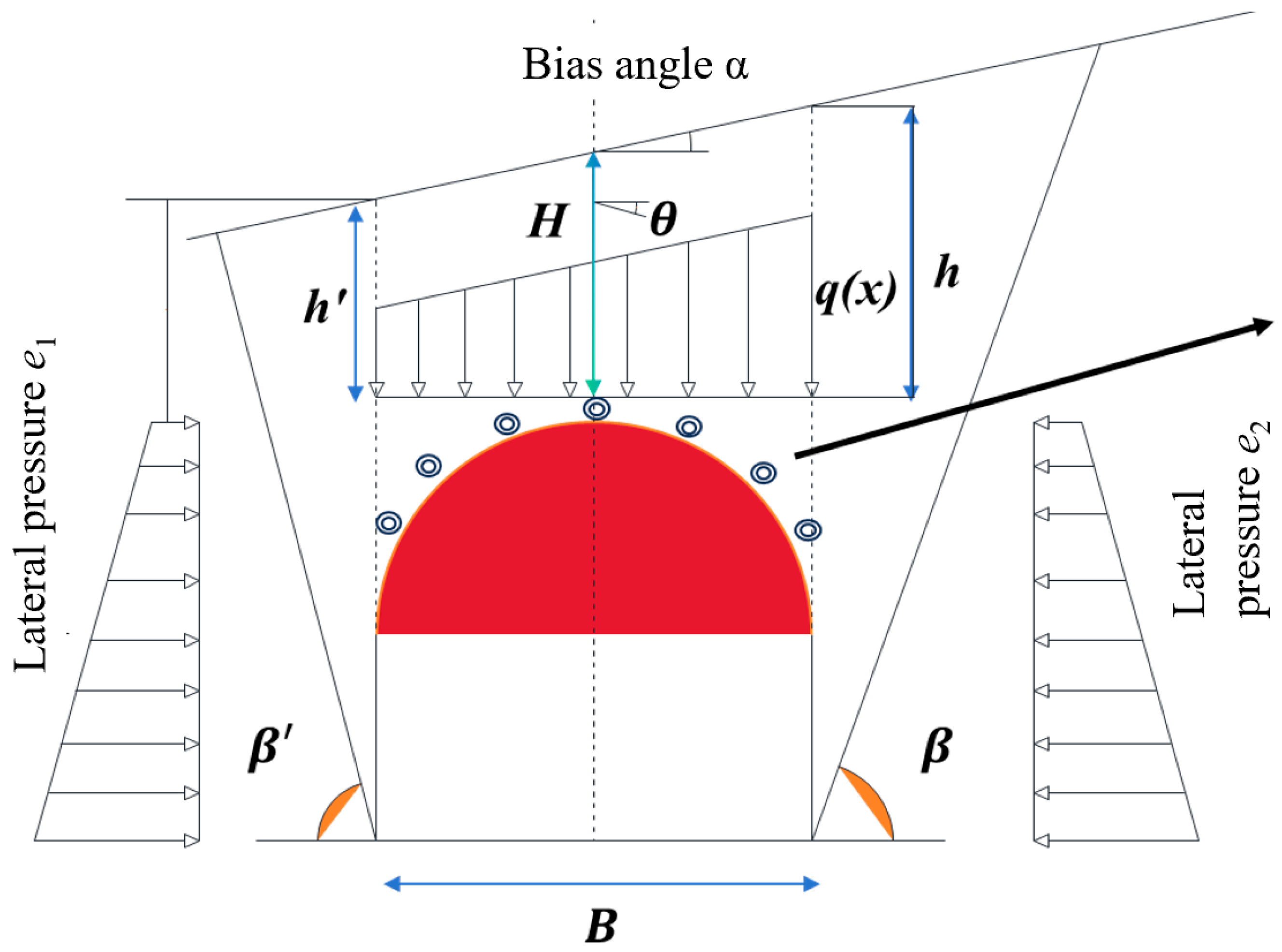
The calculation method for surrounding rock pressure under unsymmetrical loading conditions is based on the “Code for Design of Railway Tunnels” [23], which considers the influence of the unsymmetrical loading angle/ground slope angle, as shown in Figure 1. In the Figure, B is the tunnel span, α is the ground slope angle, H is the vertical distance from the tunnel vault center point to the ground, and h and h′ represent the vertical distances from the intersection points of the contour line on the higher and lower sides of the unsymmetrical loading tunnel portal with the horizontal line passing through the vault center point to the ground, respectively. φ c is the friction angle of the surrounding rock, and θ is the friction angle on both sides of the roof rock–soil column. The overlying vertical pressure for an unsymmetrical loading tunnel is shown in Equation (1):
q ( x ) = γ 2 ( h + h ) γ λ h 2 + λ h 2 tan θ 2 B = γ H γ λ h 2 + λ h 2 tan θ 2 B
where λ and λ′ is coefficient of lateral pressure on the inner and outer side, respectively, calculated according to:
λ = 1 tan β tan α × tan β tan φ c 1 + tan β ( tan φ c tan θ ) + tan φ c tan θ
λ = 1 tan β + tan α × tan β tan φ c 1 + tan β ( tan φ c tan θ ) + tan φ c tan θ
where β and β′ are the rupture angles when the maximum horizontal thrust occurs on the inner and outer sides, respectively, determined by Formulas (4) and (5):
tan β = tan φ c + ( tan 2 φ c + 1 ) ( tan φ c tan α ) tan φ c tan θ
tan β = tan φ c + ( tan 2 φ c + 1 ) ( tan φ c + tan α ) tan φ c tan θ
Here, θ can be determined according to the surrounding rock class: for Classes I, II, and III, θ = 0.9 φ c ; for Class IV, θ = (0.7–0.9) φ c ; for Class V, θ = (0.5–0.7) φ c ; and for Class VI, θ = (0.3–0.5) φ c .

2.2.2. Analysis of Inter-Pipe Micro-Arch Effect

Building upon an existing model that considers the micro-arch effect [24], the model was developed under horizontal terrain models. Here, we further consider the influence of unsymmetrical loading terrain and propose a new mechanical model considering the circumferential micro-arch effect of the pipe roof.
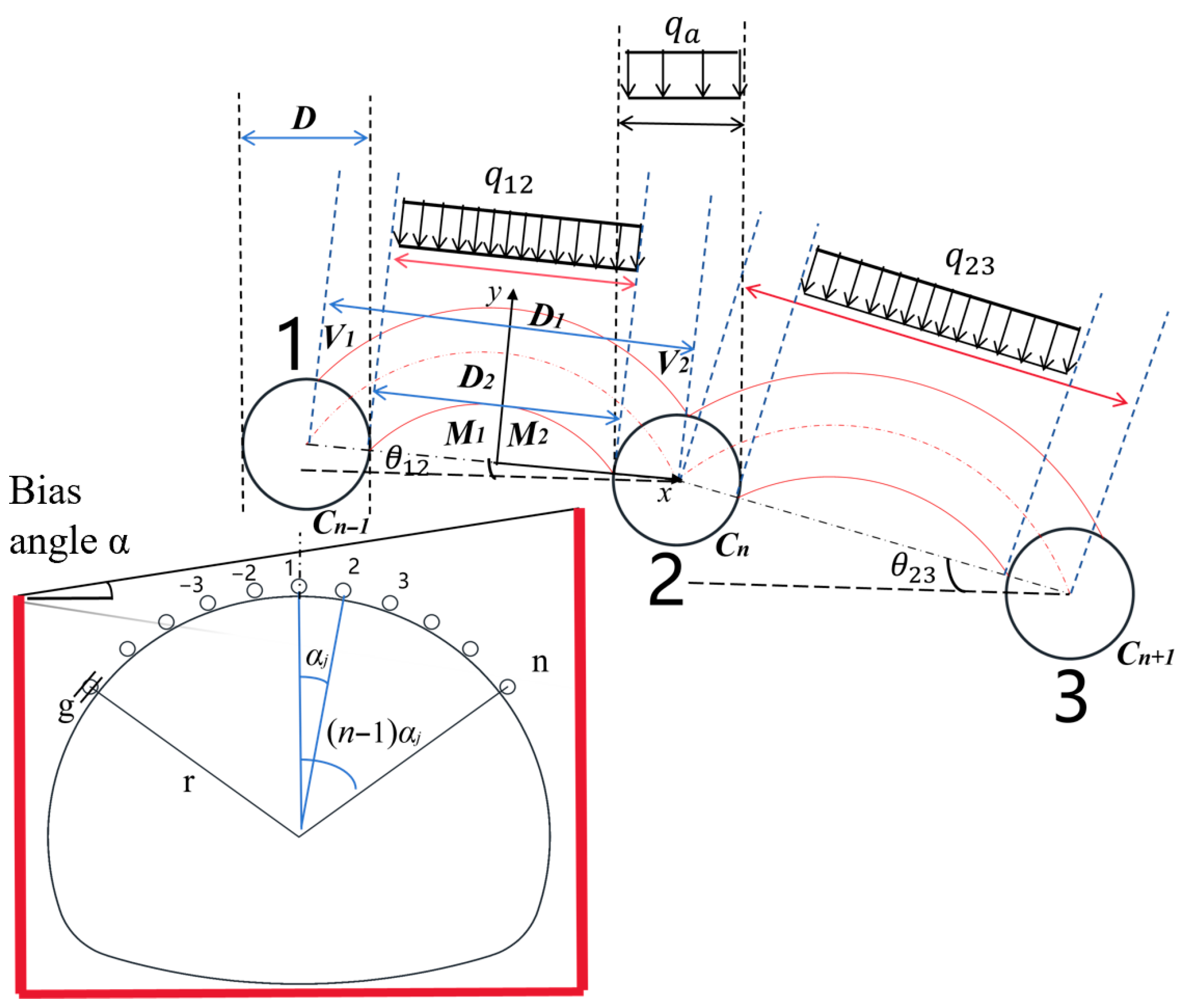
The model configuration is as shown in Figure 2, in which the pipe roof is arranged uniformly along the tunnel crown circumferentially. The steel pipe diameter is D, the center-to-center distance between adjacent steel pipes is D1, and the clear spacing is D2. The angle between adjacent steel pipes is αj, corresponding to a circumferential radius of r + g, where r is the radius of the tunnel excavation contour line, and g is the distance from the steel pipe center to the tunnel excavation contour line. Starting from the tunnel centerline, the pipe roof steel pipes are numbered sequentially. The load height above the nth steel pipe is denoted as Hn. Selecting any steel pipe Cn above the tunnel, its adjacent steel pipes are Cn−1 and Cn+1, and the horizontal angles between them and Cn are θn−1 and θn+1, respectively. Further, a Cartesian coordinate system is established with the line connecting the centers of adjacent steel pipes as the x-axis and its perpendicular bisector as the y-axis. The micro-arch axis intersects the pipe roof at points V1 and V2. The model assumptions include: ① It is assumed that Cn−1V1, CnV2, which are tangent to the arch axis, make an angle of 45° + φ/2 with the x-axis, while V1M1, V2M2, which are perpendicular to the arch axis, make an angle of 45 − φ/2 with the x-axis [25]; and ② it is assumed that the micro-arch axis is an ideal parabola that does not consider soil tensile strength, represented by the equation y = mx2 + n [26]. Based on the Cartesian coordinate system established under the above assumptions, the parameters in the parabolic equation can be expressed as follows:
m = tan π 4 + φ 2 2 R cos π 4 + φ 2 D 1
n = R sin π 4 + φ 2 + 1 4 tan π 4 + φ 2 D 1 2 R cos π 4 + φ 2
The difference between this paper and the existing model [24] is that the calculation of load on the pipe roof. Taking any pipe roof steel, e.g., pipe 2, at the tunnel crown as an example, consider the load generated by the micro-arches on both sides of the pipe roof steel pipe as the load on the pipe roof steel pipe. In this study, the load on the pipe roof steel pipe comes from two parts: one is the load qa(x) generated by the overlying soil column within the horizontal projection range of pipe roof steel pipe 2, and the other is the load qx(x) generated by the micro-arch effect formed between the three adjacent steel pipes 1, 3 and 2. The resultant vertical surrounding rock load per unit length is calculated as:
q ( x ) = D q a ( x ) + D 2 q b ( x ) D 1
The calculation of qa(x) can be referenced in Figure 2. Taking the higher side of the unsymmetrical loading as an example, for any pipe roof steel pipe (n > 1), qa(x) on the steel pipe can be calculated according to the following equation:
q a ( x ) = γ H n = γ H 1 d λ h 2 + λ h 2 tan θ 2 B + r + g ( r + g ) cos [ ( n 1 ) α j ] ( n 1 ) b tan α
where H1 is the corrected unsymmetrical loading height of the buried depth H1d of the vault steel pipe 1:
H 1 = h + h 2 λ h 2 + λ h 2 tan θ 2 B = H 1 d λ h 2 + λ h 2 tan θ 2 B
Furthermore, for the higher side of the unsymmetrical loading terrain, the calculated height of the overlying surrounding rock pressure on any small pipe n can be obtained as:
H n = H 1 + r + g ( r + g ) cos [ ( n 1 ) α j ] + ( n 1 ) b tan α
For the lower side of the unsymmetrical loading terrain, the calculated height of the overlying surrounding rock pressure on any small pipe n − 1, n, n + 1 can be expressed as:
H n 1 = H 1 + r + g ( r + g ) cos [ ( n 2 ) α j ] ( n 2 ) b tan α H n = H 1 + r + g ( r + g ) cos [ ( n 1 ) α j ] ( n 1 ) b tan α H n + 1 = H 1 + r + g ( r + g ) cos ( n α j ) n b tan α
In Equation (8), the calculation of qb(x) acting on steel pipe n is as follows:
q b ( x ) = q n 1 · n cos θ n 1 n + q n n + 1 cos θ n n + 1 2 = γ D 1 D 1 2 R cos π 4 + φ 2 H n 1 + H n 2 n + R cos θ n 1 n + H n + H n + 1 2 n + R cos θ n n + 1
where qn−1·n is the uniformly distributed micro-arch load formed between any pipe roof steel pipe n − 1 and pipe roof steel pipe n:
q n 1 n = γ H n 1 + H n 2 n + R D 1 D 1 2 R cos π 4 + φ 2
and qn·n+1 is the uniformly distributed micro-arch load formed between steel pipe n and steel pipe n + 1:
q n n + 1 = γ H n + H n + 1 2 n + R D 1 D 1 2 R cos π 4 + φ 2
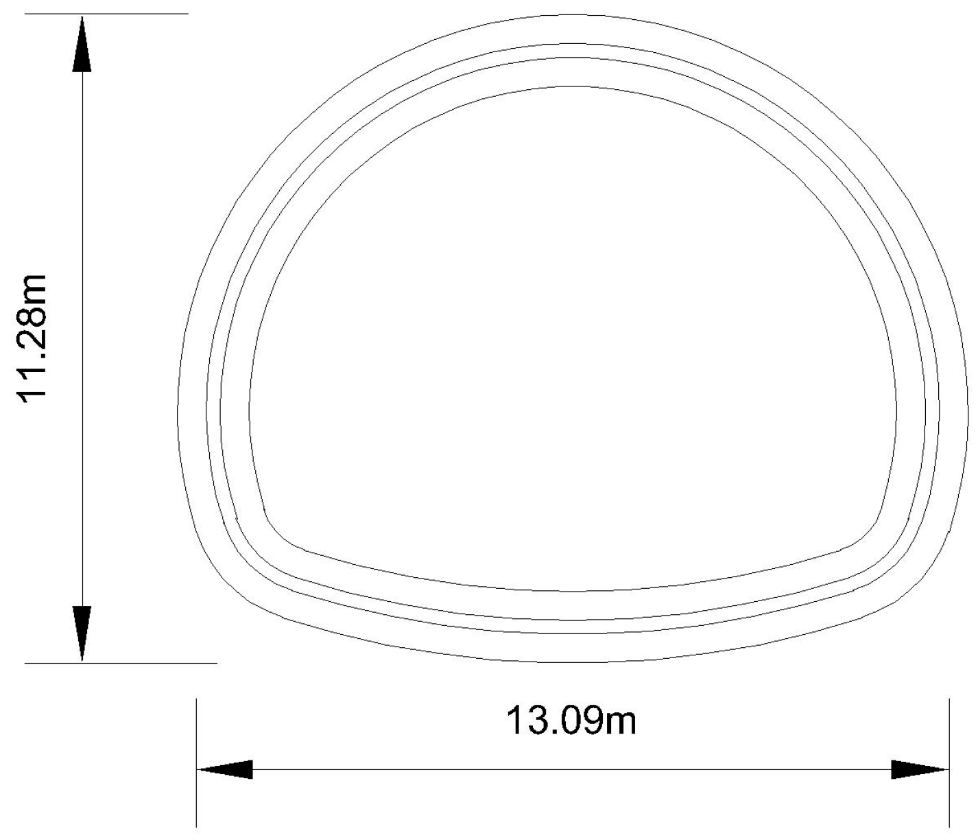
In Equation (13), it is necessary to use θ n 1 · n (or θ n + 1 · n ), which is the angle between the line connecting the centers of pipe roof steel pipe n − 1 (or n + 1) and pipe roof steel pipe n and the horizontal line. This angle is related to the tunnel dimensions. Taking the cross-sectional drawing of an actual shallow unsymmetrical loading tunnel project as an example (Figure 3), by extracting the angle data between steel pipes at different positions above the horseshoe-shaped tunnel and performing fitting, θ n 1 · n and θ n + 1 · n can be obtained as shown in Equations (16) and (17):
θ n 1 n = 5.4 n 7.8 2 π 180
θ n n + 1 = 5.4 n 2.4 2 π 180

2.2.3. Establishment of Longitudinal Mechanical Model

The inter-pipe micro-arch effect analyzed in the previous sections is then incorporated in a model developed for unsymmetrical loading [4], to establish the mechanical and deformation relationships along longitudinal directions. In the model, the pipe roof is simplified longitudinally as an Euler–Bernoulli beam and described based on the Pasternak elastic foundation theory. The Pasternak model considers the shear interaction between spring elements, characterized jointly by the soil foundation coefficient K (kN/m3) and the foundation shear modulus Gp (kN/m). According to the study by Yang et al. [4], the differential equation for the deflection control of the pipe roof can be obtained, as shown in Equation (21):
E I d 4 ω ( x ) d 4 x G P b d ω 2 ( x ) d x 2 + k b ω ( x ) = b q ( x )
where E is the equivalent elastic modulus of the pipe roof (kN/m2), I is the moment of inertia of the pipe roof cross-section (m4), ω ( x ) is the deflection of the beam at point x (m), and b is the equivalent width of the foundation shear layer (m).
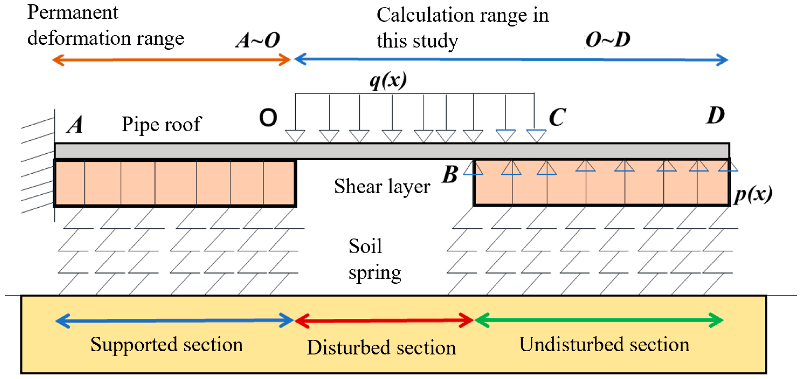
As shown in Figure 4, based on the construction characteristics of tunnel advance pipe roof support, the pipe roof is divided into four sections along the tunnel excavation direction: the supported section (AO), the excavated unsupported section (OB), the disturbed zone of the unexcavated section (BC), and the undisturbed zone of the unexcavated section (CD), as illustrated in Figure 4.
For the OB section, the pipe roof in this section is only subjected to the overlying surrounding rock load, so p(x) in Equation (18) is 0; for the BC section, the pipe roof in this section is subjected to both the overlying surrounding rock load and the foundation reaction force; for the CD section, this section is only subjected to the foundation reaction force, so q(x) in Equation (18) is 0. By solving the deflection differential equations for the OB, BC, and CD sections of the pipe roof, the deflection expressions for the different sections are obtained as shown in Formulas (19)–(21):
ω OB ( x ) = 1 24 E I b q ( x ) x 4 + π 1 x 3 + π 2 x 2 + π 3 x + π 4
ω BC ( x ) = e α 1 x ( ζ 1 cos α 2 x + ζ 2 sin α 2 x ) + e α 1 x ζ 3 cos α 2 x + ζ 4 sin α 2 x + q ( x ) k
ω CD ( x ) = e α 1 x ( ζ 1 cos α 2 x + ζ 2 sin α 2 x ) + e α 1 x ζ 3 cos α 2 x + ζ 4 sin α 2 x
where α1 and α2 are material parameters that can be calculated by Equations (22) and (23):
α 1 = 1 + G p b 1 2 2 K E I 1 2
α 2 = 1 G p b 1 2 2 K E I 1 2
and the terms π1, π2, π3, π4 and ζ1, ζ2, ζ3, ζ4 are integration constants to be determined, which can be solved by establishing eight boundary equations based on the boundary conditions. First, the starting point of the pipe roof, i.e., point A at the tunnel entrance, is considered an elastic fixed end, satisfying the conditions at x = 0, with an initial deflection ω0 and an initial rotation angle θ0, satisfying the relationship:
ω A x = 0 = ω 0 ,   θ A x = 0 = ω A x = 0 = θ 0
Meanwhile, the pipe roof satisfies displacement continuity and load continuity conditions. Therefore, the displacement and rotation angle on both sides of point B are equal. Assuming the length of the excavated section AB of the tunnel is L, the critical point between section AB and section BC, i.e., the tunnel face position B, satisfies the relationship as shown in Equation (28):
ω A B x = L = ω B C x = L ,   ω A B x = L = ω B C x = L ,   ω A B x = L = ω B C x = L ,   ω A B x = L = ω B C x = L
Finally, the pipe roof is considered as a semi-infinite elastic foundation beam, so the displacement and rotation angle at the very end of the pipe roof are neglected. Thus, the endpoint D of the pipe roof in the undisturbed zone CD can be assumed to be at x approaching infinity, where the end deflection is 0 and the end rotation angle is 0, satisfying the relationship as shown in Equation (26):
ω D x = 0 ,   θ D x = ω D x = 0
The boundary conditions are transformed into the matrix equation form as follows:
0 0 0 1 0 0 0 0 1 0 0 0 a 3 a 2 a 1 e a α 1 cos ( a α 2 ) e a α 1 sin ( a α 2 ) 3 a 2 2 a 1 0 c 45 c 46 6 a 2 0 0 c 55 c 56 6 0 0 0 c 65 c 66 π 1 π 2 π 3 π 4 ζ 3 ζ 4 = ω 0 θ 0 ρ 3 ρ 4 ρ 5 ρ 6
From Equation (23), it can be obtained that ζ1 and ζ2 are both 0, so they are not included in the matrix. The parameters on the left side of the matrix equation are:
c 45 = e a α 1 ( α 2 sin ( a α 2 ) + α 1 cos ( a α 2 ) ) ,   c 46 = e a α 1 α 1 sin ( a α 2 ) α 2 cos ( a α 2 ) c 55 = e a α 1 2 α 1 α 2 sin ( a α 2 ) ( α 1 2 α 2 2 ) cos ( a α 2 )   c 56 = e a α 1 2 α 1 α 2 cos ( a α 2 ) ( α 1 2 α 2 2 ) sin ( a α 2 ) c 65 = e a α 1 ( α 2 3 3 α 1 2 α 2 ) sin ( a α 2 ) + ( α 1 3 3 α 1 α 2 2 ) cos ( a α 2 ) c 66 = e a α 1 ( α 2 3 3 α 1 2 α 2 ) cos ( a α 2 ) + ( α 1 3 3 α 1 α 2 2 ) sin ( a α 2 )
The parameters ρ3 to ρ6 on the right side of the matrix equation are parametric expressions, whose specific forms depend on the adopted soil arching effect and unsymmetrical loading correction method:
ρ 3 = q x 1 k b a 4 24 E I ,   ρ 4 = q x b a 3 6 E I ,   ρ 5 = q x b a 2 2 E I ,   ρ 6 = q x b a E I
Based on the deflection equations for different tunnel sections, the rotation angle, bending moment, and shear force equations for different sections can be derived. Their specific forms can be expressed in matrix form as shown in Equations (30)–(32). For the 0xcavated unsupported OB section, we have the following:
ω OB ( x ) θ OB ( x ) M OB ( x ) V OB ( x ) = q x b x 1 24 E I x 3 1 6 E I x 2 1 2 x 1 + x 3 x 2 x 1 3 x 2 2 x 1 0 6 E I x 2 E I 0 0 6 E I 0 0 0 π 1 π 2 π 3 π 4
For the disturbed zone BC section of the unexcavated area in front of the tunnel face, we have the following:
ω BC ( x ) θ BC ( x ) M BC ( x ) V BC ( x ) = q x k 0 0 0 + e α 1 x cos ( α 2 x ) e α 1 x sin ( α 2 x ) e α 1 x α 2 sin ( α 2 x ) + α 1 cos ( α 2 x ) e α 1 x α 2 cos ( α 2 x ) α 1 sin ( α 2 x ) 2 E I e α 1 x α 1 α 2 sin ( α 2 x ) + ( α 2 2 α 1 2 ) cos ( α 2 x ) E I e α 1 x ( α 2 2 α 1 2 ) sin ( α 2 x ) + 2 α 1 α 2 cos ( α 2 x ) E I ( α 2 3 3 α 1 2 α 2 ) sin ( α 2 x ) E I ( 3 α 1 α 2 2 α 1 3 ) cos ( α 2 x ) E I ( 3 α 1 α 2 2 α 1 3 ) sin ( α 2 x ) E I ( 3 α 1 2 α 2 α 2 3 ) cos ( α 2 x ) ζ 3 ζ 4
For the stable zone CD section of the unexcavated area in front of the tunnel face, we have the following:
ω C D ( x ) θ C D ( x ) M C D ( x ) V C D ( x ) = e α 1 x cos ( α 2 x ) e α 1 x sin ( α 2 x ) e α 1 x α 2 sin ( α 2 x ) + α 1 cos ( α 2 x ) e α 1 x α 2 cos ( α 2 x ) α 1 sin ( α 2 x ) 2 E I e α 1 x α 1 α 2 sin ( α 2 x ) + ( α 2 2 α 1 2 ) cos ( α 2 x ) E I e α 1 x ( α 2 2 α 1 2 ) sin ( α 2 x ) + 2 α 1 α 2 cos ( α 2 x ) E I ( α 2 3 3 α 1 2 α 2 ) sin ( α 2 x ) E I ( 3 α 1 α 2 2 α 1 3 ) cos ( α 2 x ) E I ( 3 α 1 α 2 2 α 1 3 ) sin ( α 2 x ) E I ( 3 α 1 2 α 2 α 2 3 ) cos ( α 2 x ) ζ 3 ζ 4
Using Equations (30)–(32), combined with the relevant formulas for the unsymmetrical loading soil arching effect (Equation (8)), the internal forces and deformation of the pipe roof during different sections of excavation can be calculated.
Several limitations of the methodological framework employed in this study should be acknowledged. First, the optimization of the low-carbon grouting material was conducted only at a fixed water–cement ratio of 1:1, which is typical for pipe roof grouting but may not represent the full range of field conditions where water–cement ratios vary with formation permeability and grouting pressure. Second, the grout–soil reinforcement tests were performed on a single soil type (strongly weathered granite from South China); the mechanical improvements reported may differ for other lithologies (e.g., clay-rich soils, sandy strata) due to varying grout penetration and bonding mechanisms. Third, the laboratory uniaxial compression tests used standard cylindrical specimens, which cannot fully replicate the confined, three-dimensional stress state and grout distribution patterns in actual pipe roof–soil systems. Fourth, the theoretical model assumes a homogeneous, isotropic elastic foundation (Pasternak) and neglects potential time-dependent effects such as creep of the grouted soil or hardening of the grout during the construction period. Finally, the model validation was limited to comparison with the existing literature data under horizontal terrain (0° bias) due to the scarcity of field measurements under unsymmetrical loading conditions. Future work should address these limitations through parametric laboratory studies across a wider range of soil types and water–cement ratios, as well as full-scale field validation under controlled bias angles.

3. Results

3.1. Performance of New Low-Carbon Cement-Based Grouting Slurry and Its Effect on Reinforced Soil

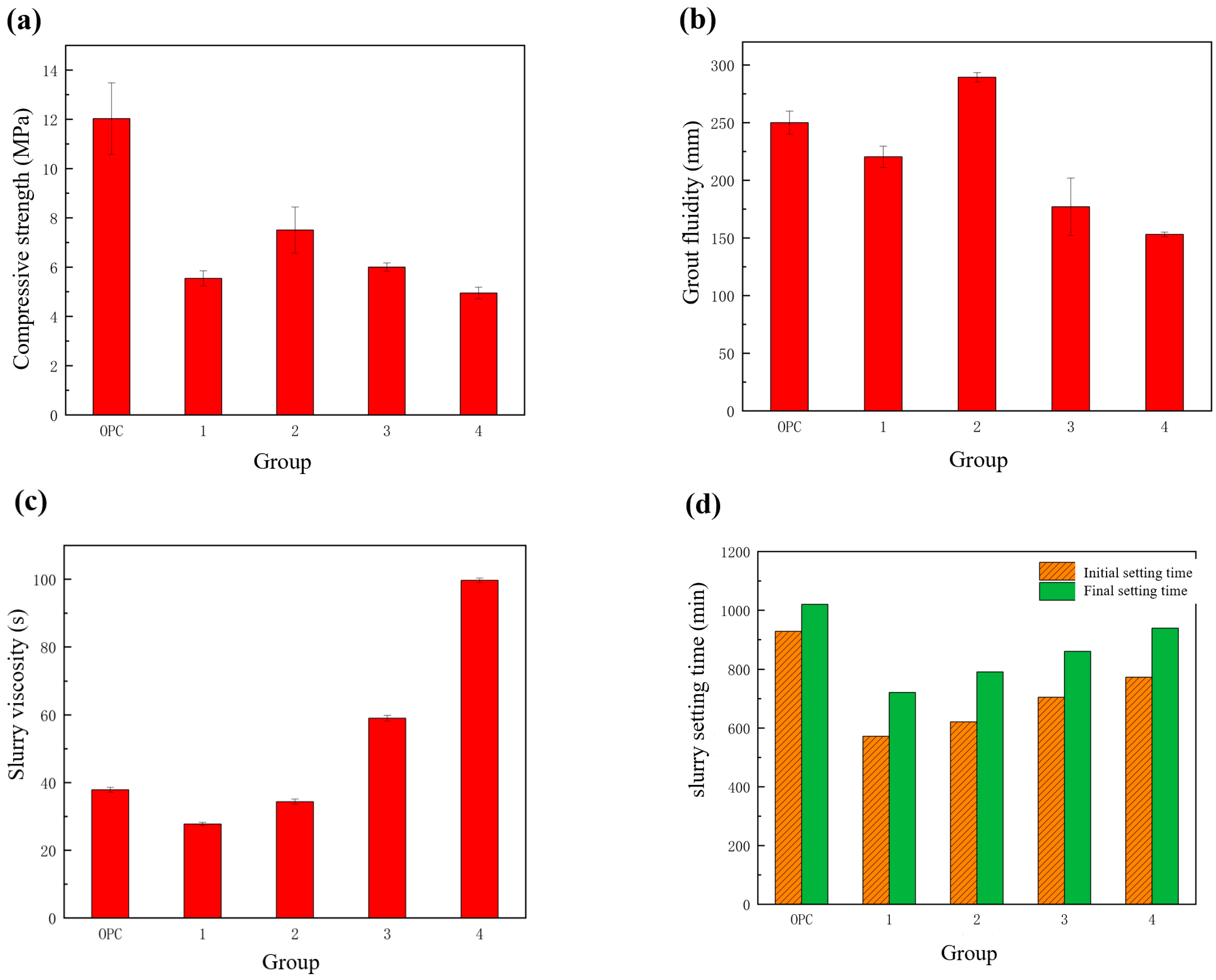
The performance test results of the new low-carbon cement-based grouting slurry are shown in Figure 5. The 28-day compressive strength of the slurry initially increases and then decreases with the change in the mass ratio of limestone to calcined kaolin (Figure 5a). Under Mix Ratio 2 (25% limestone, 20% kaolin), the compressive strength is the highest, exceeding 7 MPa; while under Mix Ratio 4 (35% limestone, 10% kaolin), the strength is the lowest, at only about 5 MPa. The strengths under all mix ratios did not reach 75% of the OPC42.5 cement slurry. Fluidity tests (Figure 5b) show that the slurry under Mix Ratio 2 exhibits optimal fluidity, close to 300 mm, significantly better than traditional cement slurry, which is beneficial for field grouting construction. Viscosity tests (Figure 5c) further indicate that the viscosity of the Mix Ratio 2 slurry is about 30 s, slightly lower than that of OPC42.5 cement slurry (about 40 s), demonstrating good diffusion capacity; and the Mix Ratio 4 slurry has excessively high viscosity (close to 100 s), which is unfavorable for grouting operations. Regarding setting time (Figure 5c), all low-carbon slurry mix ratios exhibit early setting characteristics, with initial and final setting times ranging from 500 to 1000 min, shorter than PO42.5 cement slurry (900–1100 min). As the limestone proportion increases, the setting time is prolonged, which is attributed to the retarding effect due to the lower activity of limestone, while the active alumina in calcined kaolin helps promote setting. Based on a comprehensive evaluation of various performance indicators, Mix Ratio 2 (50% cement clinker, 5% gypsum, 25% limestone, and 20% calcined kaolin) is determined as the optimal mix ratio. This mix ratio demonstrates good comprehensive performance in terms of strength, fluidity, viscosity, and setting time.
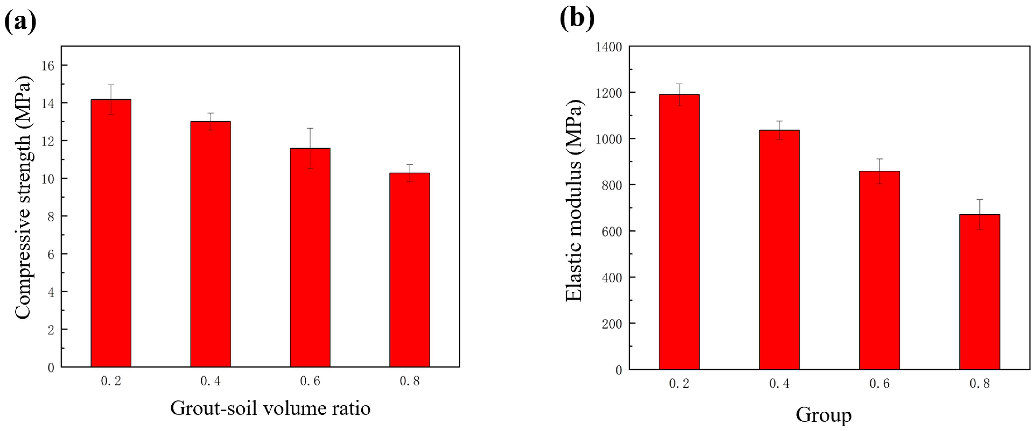
The mechanical performance test results of the new low-carbon grouting liquid-reinforced completely weathered granite are shown in Figure 6. Uniaxial compression tests indicate that the slurry–highly weathered granite residual soil mixture reinforcement bodies exhibit good mechanical properties under all different grout-to-soil volume ratios (0.2, 0.4, 0.6, and 0.8). Compressive strength tests (Figure 6a) show that the compressive strength of the reinforcement bodies under all mix ratios exceeds 10 MPa, which is higher than the average strength of the pure slurry stone body. As the grout-to-soil volume ratio increases from 0.2 to 0.8, the compressive strength shows a decreasing trend, mainly because the increase in slurry proportion leads to an increase in the overall water–cement ratio, weakening the reinforcement effect. Elastic modulus test results (Figure 6b) show that the elastic modulus of the reinforcement bodies exceeds 600 MPa. When the grout-to-soil volume ratio is 0.2, the elastic modulus approaches 1200 MPa; even under the condition of a grout-to-soil volume ratio of 0.8, the elastic modulus remains above 600 MPa. As the grout-to-soil volume ratio increases, the elastic modulus also shows a decreasing trend.

3.2. Model Validation and Theoretical Analysis of Low-Carbon Cement Reinforcement Effect

Due to the scarcity of reported field measurement data for shallow unsymmetrical loading conditions in the literature, this paper validates the calculation model using engineering measurement parameters from a shallow non-unsymmetrical loading condition [4]. Furthermore, a parametric analysis under shallow unsymmetrical loading conditions is conducted to investigate the influence of the unsymmetrical loading angle on the mechanical behavior of pipe roof steel pipes at different positions.

3.2.1. Model Validation

The Birgl tunnel in Austria used for validation has a horseshoe-shaped cross-section, similar in dimensions to the cross-section in Figure 5, so Equations (16) and (17) are considered applicable to this tunnel. The tunnel has a lateral width of approximately 15 m, and with a burial depth of 30 m, it meets the shallow condition. The pipe roof consists of 29 steel pipes with an installation angle of 2.5°. Relevant physical parameters for the pipe roof construction area are detailed in Table 3.
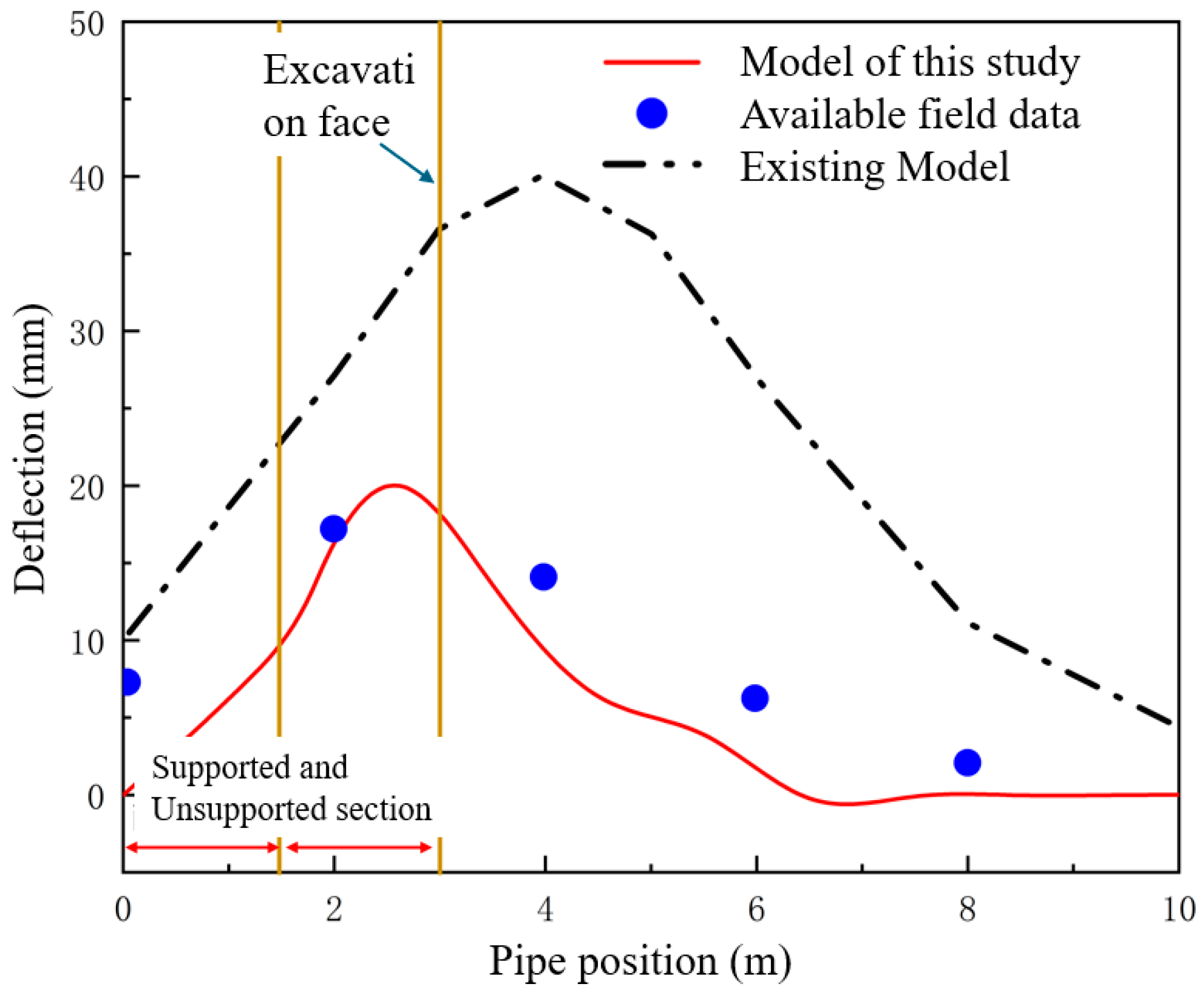
Since the field measurement data were obtained from deflection inclinometers installed on the vault steel pipe (as cited in the referenced literature [27]), the validation of the theoretical model in this paper focuses on the vault steel pipe. Figure 7 shows the steel pipe deflection calculated by the pipe roof mechanical model proposed in this paper, calculated for the condition where the tunnel is excavated to a point 3 m from the tunnel portal. The model is validated by comparing the calculation results of this paper with field test data [27] and the calculation results of existing related theoretical models [28].
As shown in Figure 7, when the unsymmetrical loading angle is 0 and the tunnel is excavated to a point 3 m from the tunnel portal, the deflection predicted by the calculation model in this paper is consistent with the predictions of existing models and field test data, with the trend showing that the absolute deflection initially increases and then decreases, reaching its maximum near the excavation face. In the unsupported area ahead of the excavation face, the pipe roof undergoes maximum deformation due to the lack of support from the foundation reaction force under the overlying rock mass load. The maximum deflection obtained in this paper is closer to the field monitoring data compared to existing related models (see [29]). Moreover, the location of the maximum pipe roof deflection predicted in this paper is closer to the location of the maximum pipe roof deflection obtained from field measurement data, further validating the rationality and advancement of the proposed model.

3.2.2. Parametric Analysis of Reinforced Pipe Roof Effect Using Low-Carbon Cement Grout

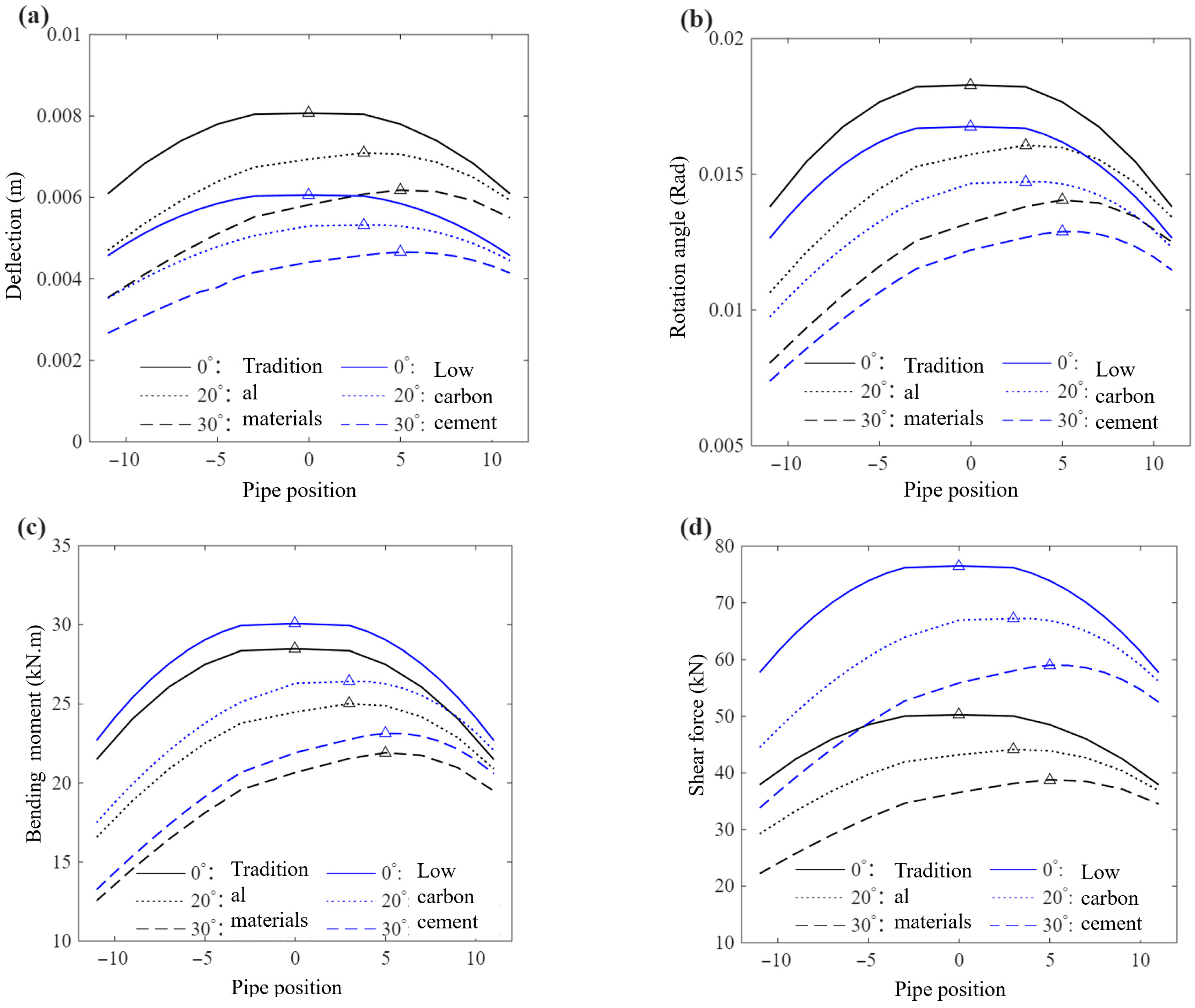
To analyze the characteristics of internal forces and deformation of the pipe roof system on the transverse plane under different unsymmetrical loading angles, we take the parameters of the Austrian Birgl tunnel as an example. In the calculation, it is assumed that the initial displacement and rotation angle at the starting end of the pipe roof are zero, the tunnel face is located 1.5 m from the portal, and the steel pipe at the vault position of the pipe roof is taken as the coordinate origin (as shown in Figure 8). All steel pipes on the right side (the higher side of the unsymmetrical loading terrain) of the vault steel pipe are sequentially named Steel Pipe 2, 3, 4 … n, and all steel pipes on the left side (the lower side of the unsymmetrical loading terrain) of the vault steel pipe are sequentially named Steel Pipe −2, −3, −4 … −n. The peak responses of bending moment, shear force, deflection, and rotation angle of each steel pipe under unsymmetrical loading are investigated.
Figure 8 illustrates the distribution of forces and deformation of the pipe roof on the transverse plane under different unsymmetrical loading angles. Under horizontal terrain (unsymmetrical loading angle of 0°), the maximum deflection, rotation angle, bending moment, and shear force all occur at the vault pipe (pipe No. 1). The response distribution is symmetric about the tunnel centerline, with values gradually decreasing as the pipe number (i.e., the horizontal distance from the vault) increases. Consequently, under symmetric loading conditions, the vault represents the most critical location.
When the terrain exhibits unsymmetrical loading, the response distribution changes significantly (Figure 8). At a bias angle of 20°, the location of maximum deflection shifts from the vault to pipe No. 3; at 30°, it further shifts to pipe No. 5. This progressive migration indicates that as the unsymmetrical loading angle increases, the most critical position of the pipe roof system moves from the crown toward the higher side of the terrain. Moreover, the deformation and internal force peaks on the higher-side pipes become substantially larger than those on the lower side, and the previously symmetric distribution becomes increasingly asymmetric. The asymmetry intensifies with the bias angle, manifesting as enhanced response on the higher side and relatively weakened response on the lower side.
Figure 8 also compares the theoretical responses obtained using the proposed low-carbon cement grouting material versus traditional grouting materials (e.g., OPC). In the calculation, the low-carbon material uses the Young’s modulus corresponding to a grout-to-soil volume ratio of 0.2, with all other parameters kept identical. Following the method of Lu et al. [30], the foundation coefficient K in the Pasternak foundation theory increases from 86,000 kN/m3 to approximately 888,565 kN/m3, and the shear modulus G increases from 12,500 kN/m to approximately 129,375 kN/m—both by a factor of about 10. The theoretical analysis shows that the trends of deformation and internal forces with position remain essentially the same as for traditional materials, and the locations of extreme values on the steel pipes are unchanged. However, the use of low-carbon material significantly reduces pipe roof deflection while causing a corresponding increase in bending moment and shear force within the pipes. This trade-off arises because the increased stiffness of the surrounding soil restricts pipe deformation, which in turn induces higher internal forces.

4. Discussion

The experimental results for the LC3 grout in this study were obtained specifically at a water–cement ratio of 1:1, which is considered suitable for grouting applications in tunnel pre-support. In contrast, most of the existing literature on LC3-based materials focuses on concrete or paste with low water–cement ratios (0.4–0.5) for structural applications. For example, Ruan et al. [22] reported that LC3 cement paste at a water–cement ratio of 0.5 achieves a 28-day compressive strength exceeding 40 MPa, and at a ratio of 0.4, it reaches above 50 MPa. These values are substantially higher than the 8.6 MPa obtained in this study at a water–cement ratio of 1:1, which is expected because a higher water content increases porosity and consequently reduces strength. When compared under identical conditions (water–cement ratio = 1:1), the LC3 grout achieved approximately 85% of the compressive strength of ordinary Portland cement (OPC) grout (8.6 MPa vs. 10.7 MPa). This level of strength is considered acceptable for pipe roof pre-support, where deformability and injectability often take precedence over ultimate strength.
To quantify the environmental impact and material cost per unit of compressive strength of the proposed low-carbon grouting material compared to traditional cement grout (PO42.5), we adopted the method described in reference [31] to calculate the carbon emission index (CI28) and material cost index (COST28) of the grout after 28 days of curing. The calculation uses three parameters: CE1k9 (gCO2/kg of grout material), MC1k9 (HKD/kg of grout material), and CS28 (MPa, the 28-day standard compressive strength of the neat grout). Based on the carbon emission and cost data for LC3-50 cement and ordinary Portland cement provided in [31], together with our experimental results, the low-carbon grout exhibits a CE1k9 of 580 gCO2/kg, an MC1k9 of 0.60 HKD/kg, and a CS28 of 8.60 MPa. In comparison, the traditional cement grout shows a CE1k9 of 900 gCO2/kg, an MC1k9 of 0.71 HKD/kg, and a CS28 of 10.67 MPa. Using these values, the calculated CI28 and COST28 indicate that the COST28 of the low-carbon grout is very close to that of the traditional grout, whereas its CI28 is substantially lower. This means that, for achieving the same target strength in practical reinforcement applications, the production cost per unit weight of the low-carbon grout is comparable to that of the traditional grout, but its carbon emissions during production are significantly lower. Therefore, the low-carbon grout offers a clear environmental advantage, particularly in urban settings where environmental protection is a priority. For shallow tunnels where deformation control (and thus surface settlement) is the primary design criterion, the low-carbon material offers a clear advantage. For deep tunnels or those with high overburden, the increased internal forces should be checked against the pipe’s structural capacity.
Under horizontal terrain (0° bias angle), the maximum deflection and internal forces occur at the vault pipe, which is consistent with previous findings under symmetric loading conditions [1,2,24] and the limited investigations considering unsymmetric loading conditions [4,32]. However, the limited studies that considered unsymmetric loading conditions did not present results on the transverse plane under different unsymmetrical loading angles. For unsymmetric loading conditions, we find that the asymmetry intensifies with the bias angle, manifesting as enhanced response on the higher side and relatively weakened response on the lower side. Under symmetric loading conditions, our results show that the vault represents the most critical location, and a simplified model focusing on the vault pipe is sufficient for analysis and design, results consistent with current studies considering symmetrical loading conditions [1,2,24]. Furthermore, compared to traditional models, the calculation model in this paper, when calculating the overlying load on the pipe roof, simultaneously considers the influence of the soil’s mechanical properties (including internal friction angle) and the inter-pipe micro-arch effect, which is more consistent with the actual contact behavior between the pipe roof and soil under shallow conditions. Therefore, the presented results shed light on how the location of maximum deflection and internal forces shifts with the bias angle. These findings lead to the following recommendations for practice: (a) prioritize field monitoring on the higher-side pipes; (b) increase grouting volume locally on the higher side (e.g., by 30–50% compared to the lower side); and (c) consider an asymmetric pipe roof layout in highly biased terrains (bias angle > 20°).
A limitation of the current parametric analysis is its assumption of uniform grouting quality; future studies should investigate the effect of spatially variable grout distribution. Furthermore, the overlying soil was considered either dry or saturated, which may differ from practical conditions. Incorporating the soil–water characteristic curve and its influence on mechanical behavior would be beneficial.

5. Conclusions

(1). A low-carbon cement-based grouting material (LC3-50 with an optimal mix ratio of 50% cement clinker, 5% gypsum, 25% limestone, and 20% calcined kaolin) was developed for pipe roof reinforcement in shallow tunnels. Compared to traditional PO42.5 cement slurry at the same water–cement ratio of 1:1, the new material exhibits 28-day compressive strength exceeding 7 MPa (approximately 85% of OPC), fluidity close to 300 mm (30% higher than OPC), and reduced viscosity, together with a 15–20% shorter setting time. These properties significantly improve grout injectability and early strength gain. Grout–soil mixture tests on completely weathered granite (a typical shallow-tunnel soil) show that even at a grout-to-soil volume ratio of 0.8, the reinforced material achieves compressive strength > 10 MPa and elastic modulus > 600 MPa—values that meet or exceed typical design requirements for tunnel pre-support. Calculated carbon emission index and material cost index of the grout after 28 days of curing show that for achieving the same target strength in practical reinforcement applications, the production cost per unit weight of the low-carbon grout is comparable to that of the traditional grout, but its carbon emissions during production are significantly lower.
(2). A new mechanical model was established based on the Pasternak two-parameter foundation theory, which simultaneously accounts for (a) unsymmetrical loading terrain (via code-recommended surrounding rock pressure formulas) and (b) the inter-pipe micro-arch effect (derived from parabolic arching between adjacent steel pipes). Under horizontal terrain (0° bias), the model’s deflection predictions align well with existing theoretical trends, and the peak deflection (at the excavation face) shows closer agreement with field monitoring data from the Birgl tunnel than previous models—deviations are within 12% less than earlier models. This improvement confirms the model’s enhanced reliability for shallow tunnel conditions.
(3). The parametric study reveals a fundamental shift in pipe roof behavior as the bias angle increases from 0° to 30°: (a) Under horizontal terrain, forces and deformations are symmetrically distributed around the vault, with the vault being the most critical location; (b) under unsymmetrical loading, the overall response magnitude decreases slightly, but the higher side of the terrain experiences significantly larger deformations and internal forces (up to 1.8 times those on the lower side at 30° bias). (c) The location of maximum deflection and internal forces shifts progressively from the vault (0°) to pipe No. 3 (20°) and further to pipe No. 5 (30°).
(4). Using the established model with material properties derived from the grout–soil mixture tests (grout-to-soil volume ratio of 0.2), the low-carbon grouting material increases the Pasternak foundation coefficient K by approximately 10-fold and the shear modulus G by a similar factor, following the method of Lu et al. [30]. Theoretical analysis shows that this stiffness enhancement reduces pipe roof deflection by around 20% compared to traditional grouting materials, but at the cost of increasing bending moment slightly and shear force significantly within the steel pipes. This trade-off is acceptable for shallow tunnels where deformation control (and thus surface settlement) is the primary design criterion. The results highlight that the low-carbon material is most advantageous in stiffness-sensitive applications; for deep tunnels or those with high overburden, the increased internal forces should be checked against pipe capacity.
This study provides both a low-carbon material solution and an improved theoretical tool for the design of pipe roof support in shallow unsymmetrical loading tunnels. The main beneficiaries are tunnel design engineers (who can use the model for more accurate deflection predictions and material selection) and construction managers (who can optimize grouting volumes on the higher side). Future research should focus on: (a) full-scale field validation of the model under controlled bias conditions; (b) experimental calibration of the micro-arch effect parameters for different soil types; and (c) extension of the model to consider sequential grouting and time-dependent material hardening.

Author Contributions

Conceptualization, J.C. and H.Y.; methodology, Z.X.; validation, Z.X., J.C. and H.Y.; formal analysis, M.H. and Z.X.; investigation, Z.X.; data curation, Z.X.; writing—original draft preparation, J.C. and H.Y.; writing—review and editing, M.H.; supervision, H.Y.; project administration, J.C., M.H. and X.L. All authors have read and agreed to the published version of the manuscript.

Funding

This research received no external funding.

Data Availability Statement

Dataset available on request from the authors.

Conflicts of Interest

Author Jingsong Chen, Mu He and Xiaodong Li were employed by the company Guangzhou North 2nd Ring Road Transportation Technology Co., Ltd. The remaining authors declare that the research was conducted in the absence of any commercial or financial relationships that could be construed as a potential conflict of interest.

References

  1. Xu, X.J.; Song, Z.P.; Li, H.; Tian, X.X.; Zhou, G.N. Mechanical Model and Parameter Analysis of Tunnel Pipe Shed Considering Arch Effect. Chin. J. Undergr. Space Eng. 2023, 19, 95–106, 132. [Google Scholar]
  2. Song, Z.P.; Tian, X.X.; Zhou, G.N.; Yang, Y.; Lu, M. Theoretical Analysis of Mechanical Behavior of Advanced Pipe Roof Support in Tunnel. Chin. J. Highw. Transp. 2020, 33, 89–98. [Google Scholar]
  3. Wu, Y.H.; Xiao, C.J.; Chen, F.Q.; Liu, Z.Q. Study on Mechanical Characteristics of Pipe Umbrella Support in Shallow Buried Tunnels. Tunn. Undergr. Space Technol. 2024, 145, 105578. [Google Scholar] [CrossRef]
  4. Yang, H.W.; Xu, Z.H.; Huang, L.C.; Zhang, Y.J. A Pasternak foundation-based theoretical model for pipe roof support in shallow buried biased pressure tunnel. J. Railw. Sci. Eng. 2025, 22, 3148–3159. [Google Scholar]
  5. Wang, D.Y.; Yuan, J.X.; Li, J.; Wang, L. Prediction of Deformation of Pipe Roof in Shallow Weak Tunnel Entrance Section Considering Construction Characteristics and Engineering Application. Chin. J. Rock Mech. Eng. 2017, 36, 716–724. [Google Scholar]
  6. Chen, H.J.; Liu, X.R.; Du, L.B.; Wang, Q. Sliding Failure Mechanism and Its Criterion of Unsymmetrical Loading Shallow Buried Tunnel in Layered Rock Mass. Chin. J. Undergr. Space Eng. 2021, 17, 1733–1741. [Google Scholar]
  7. Yao, Z.H.; Yang, Q.; Li, H.; Chen, G. Study and Application of Dual-component Synchronous Grouting Technology in Shield Tunnelling. Mod. Tunn. Technol. 2025, 62, 265–273. [Google Scholar]
  8. Li, X.; Xu, J.Z.; Liu, R.T.; Zhang, L. Study and Application of a New Acid Water Glass Grouting Material. Tunn. Constr. 2017, 37, 1296–1302. [Google Scholar]
  9. Zhang, C.; Fu, J.; Yang, J.; Wang, Y. Formulation and Performance of Grouting Materials for Underwater Shield Tunnel Construction in Karst Ground. Constr. Build. Mater. 2018, 187, 327–338. [Google Scholar] [CrossRef]
  10. Jiang, B.; Wu, M.; Wu, S.; Li, J. A Review on Development of Industrial Solid Waste in Tunnel Grouting Materials: Feasibility, Performance, and Prospects. Materials 2023, 16, 6848. [Google Scholar] [CrossRef] [PubMed]
  11. Zhou, Z.; Deng, Z.X.; Yan, H.T.; Liu, X. Experimental Study on New Green Grouting Material of Karst Area Tunnel. J. Railw. Eng. 2023, 40, 63–68. [Google Scholar]
  12. Niu, X.X. Development and application of new green environmental materials for drilling protection and grouting reinforcement. Coal Chem. Ind. 2022, 45, 112–113. [Google Scholar]
  13. Dong, Y.M.; Qian, X.; Hu, C.L.; Wang, Z. New Cementitious Material: Advances in Limestone Calcined Clay Cement. J. Chin. Ceram. Soc. 2023, 51, 2446–2464. [Google Scholar]
  14. Dhandapani, Y.; Sakthivel, T.; Santhanam, M.; Marthong, C. Mechanical Properties and Durability Performance of Concretes with Limestone Calcined Clay Cement (LC3). Cem. Concr. Res. 2018, 107, 136–151. [Google Scholar] [CrossRef]
  15. Barbhuiya, S.; Nepal, J.; Das, B.B. Properties, Compatibility, Environmental Benefits and Future Directions of Limestone Calcined Clay Cement (LC3) Concrete: A Review. J. Build. Eng. 2023, 79, 106987. [Google Scholar] [CrossRef]
  16. GB/T 50081-2019; Standard for Test Methods of Physical and Mechanical Properties of Concrete. China Architecture & Building Press: Beijing, China, 2019.
  17. GB/T 17671-2021; Method of Testing Cements—Determination of Strength (ISO Method). Standards Press of China: Beijing, China, 2021.
  18. GB/T 1346-2024; Test Methods for Water Requirement of Normal Consistency, Setting Time and Soundness of Cement. Standards Press of China: Beijing, China, 2024.
  19. GB/T 8077-2012; Test Methods for Uniformity of Concrete Admixtures. Standards Press of China: Beijing, China, 2012.
  20. DL/T 5815-2020; Test Code for Wall-Protecting Mud of Hydropower and Water Resources Project. China Electric Power Press: Beijing, China, 2020.
  21. JTG/T 3660-2020; Technical Specifications for Construction of Highway Tunnels. China Communications Press: Beijing, China, 2020.
  22. Ruan, Y.; Jamil, T.; Hu, C.; Wang, A. Microstructure and mechanical properties of sustainable cementitious materials with ultra-high substitution level of calcined clay and limestone powder. Constr. Build. Mater. 2022, 314, 125416. [Google Scholar] [CrossRef]
  23. TB 10003-2016; Code for Design of Railway Tunnels. China Railway Publishing House: Beijing, China, 2016.
  24. Li, R.; Wang, S.T.; Wang, J.F.; Chen, Y. Mechanical behaviors and supporting effect evaluation of pipe roof in tunneling engineering considering micro-arch effects. Chin. J. Geotech. Eng. 2023, 45, 561–570. [Google Scholar]
  25. Chen, Z.; He, P.; Yan, D.M.; Zhou, J. A method to calculate rational spacing between pipes in pipe roofs considering soil arching effects. Rock Soil Mech. 2019, 40, 1993–2000. [Google Scholar]
  26. Li, P.F.; Wang, F. Calculation Method of Loosening Pressure for Deep-buried and Non-symmetry Closely-spaced Tunnels. J. Beijing Univ. Technol. 2017, 43, 612–620. [Google Scholar]
  27. Van der Meer, M.G. Pipe Roof Support Interaction Measured by Chain Inclinometers at the Birgltunnel. Rock Mech. Rock Eng. 2003, 7, 105–109. [Google Scholar]
  28. Oke, J.; Vlachopoulos, N.; Diederichs, M.S. Semi-analytical model for umbrella arch systems employed in squeezing ground conditions. Tunn. Undergr. Space Technol. 2016, 56, 136–156. [Google Scholar] [CrossRef]
  29. Zhang, Z.; Li, H.; Liu, H.; Wang, W. Load transferring mechanism of pipe umbrella support in shallow-buried tunnels. Tunn. Undergr. Space Technol. 2014, 43, 213–221. [Google Scholar] [CrossRef]
  30. Lu, X.J. Mechanical mechanism of piperoofs based on the pasternak model with variable coefficient of subgrade reaction. Fujian Archit. Constr. 2016, 6, 58–62. [Google Scholar]
  31. Yu, J.; Wu, H.L.; Mishra, D.K.; Zhang, J. Compressive strength and environmental impact of sustainable blended cement with high-dosage limestone and calcined clay (LC2). J. Clean. Prod. 2021, 278, 123616. [Google Scholar] [CrossRef]
  32. He, M.; Wang, Y.; Li, M.; Chen, X. A Theoretical Model for Pipe Roof Support Considering the Micro-arch Effect between Pipes in Shallow Buried Tunnels under Biased Pressure Conditions. Mod. Tunn. Technol. 2025, 62, 31–39. [Google Scholar]
Figure 1. Stress mode of shallow-buried bias tunnel.
Applsci 16 03863 g001
Figure 2. Pipe shed circumferential load model.
Applsci 16 03863 g002
Figure 3. A typical cross-section of a shallow-buried tunnel.
Applsci 16 03863 g003
Figure 4. Simplified longitudinal stress model of pipe shed.
Applsci 16 03863 g004
Figure 5. Performance of the new low-carbon cement-based grouting material. Results of (a) 28-day compressive strength of hardened grout, (b) grout fluidity, (c) slurry viscosity, and (d) slurry setting time.
Applsci 16 03863 g005
Figure 6. The mechanical effect of the new low-carbon grouting liquid in reinforcing weathered granitic soils. (a) Uniaxial compressive strength and (b) elastic modulus.
Applsci 16 03863 g006
Figure 7. Comparison of the model in this paper with the monitoring data [27] and related models [28].
Applsci 16 03863 g007
Figure 8. The distribution of (a) deflection, (b) rotation angle, (c) bending moment, and (d) shear force of steel pipes in the pipe shed on the transverse plane under different bias pressure angles. Peak value of each curve is denoted by the triangle mark.
Applsci 16 03863 g008
Table 1. The proportion of the mass of each component of the low-carbon cement slurry.
ComponentLimestoneKaolinGypsumCement Clinker
Group 120%25%5%50%
Group 225%20%5%50%
Group 330%15%5%50%
Group 435%10%5%50%
Table 2. Physical and mechanical properties of granitic soil.
ParameterMoisture Content/%Wet Density/g/cm3Dry Density/g/cm3Specific GravityVoid Ratio
Granitic Soil21.81.911.562.720.75
Saturation/%Liquid Limit/%Plastic Limit/%Cohesion/KPaInternal Friction Angle/°
80.8835.2922.1131.6521.46
Table 3. Physical and mechanical parameters.
Tunnel Depth/mElastic Modulus/MPaSteel Pipe Diameter/mmSteel Pipe Wall Thickness/mmSteel Pipe Spacing/cmInternal Friction Angle/°Soil Unit Weight/kN/m3
301001146.3403018.5
Disclaimer/Publisher’s Note: The statements, opinions and data contained in all publications are solely those of the individual author(s) and contributor(s) and not of MDPI and/or the editor(s). MDPI and/or the editor(s) disclaim responsibility for any injury to people or property resulting from any ideas, methods, instructions or products referred to in the content.