3.3.1. Numerical Model
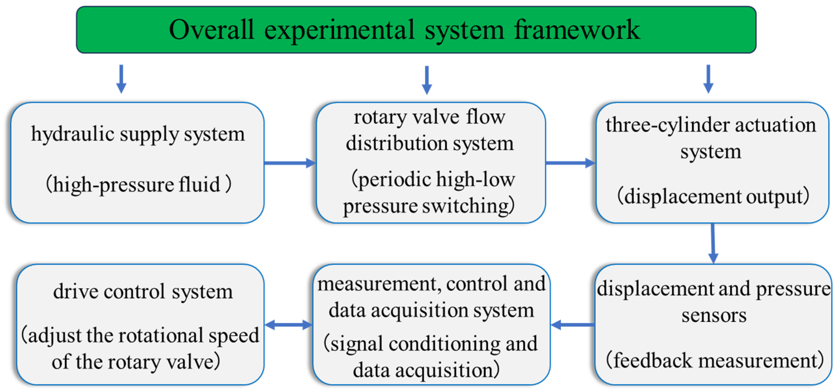
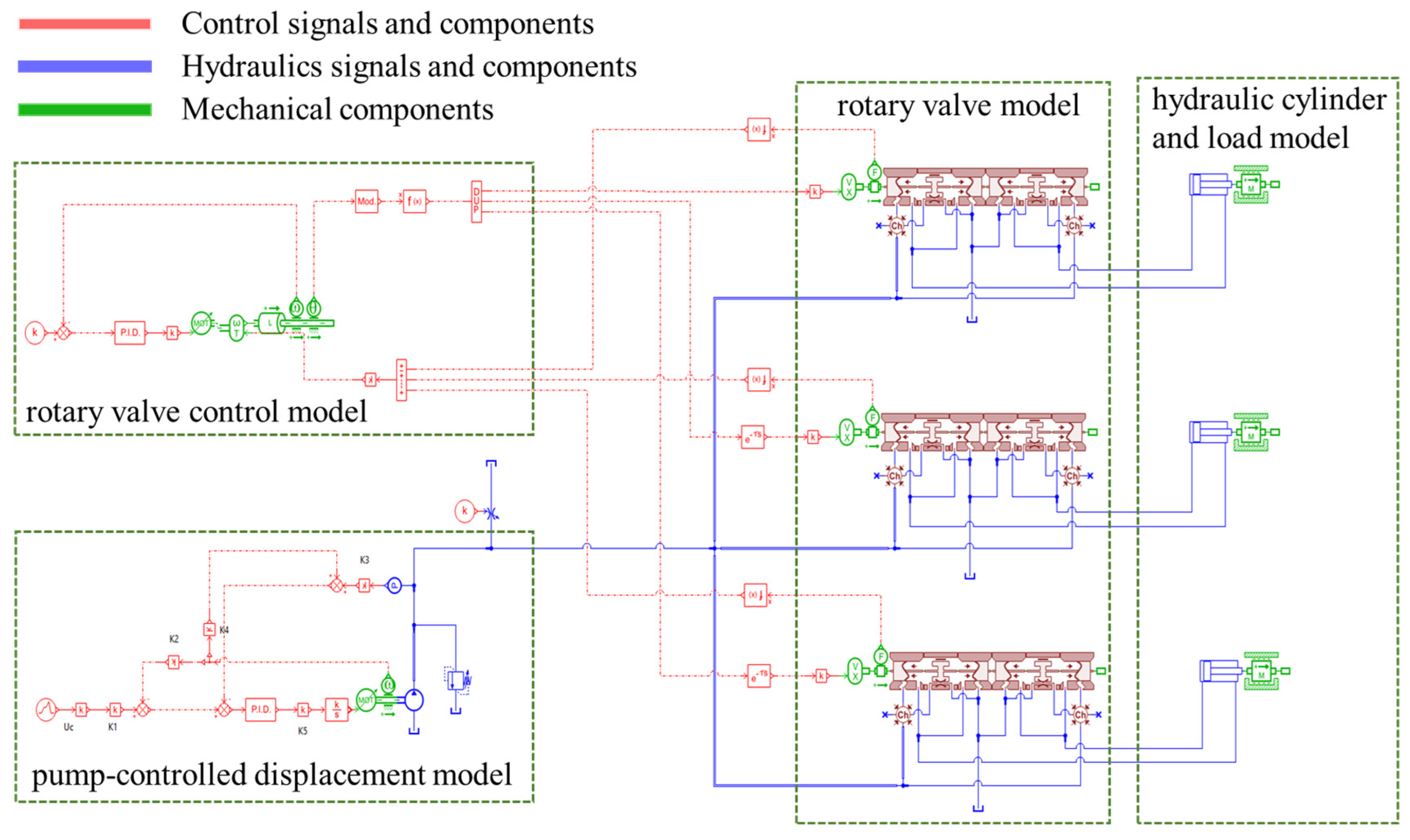
To systematically investigate the factors influencing the piston displacement of the three hydraulic cylinder through numerical simulation, based on the aforementioned tests, an integrated simulation model of the offset steering system for the rotary steerable tool was established on the AMESim simulation platform [
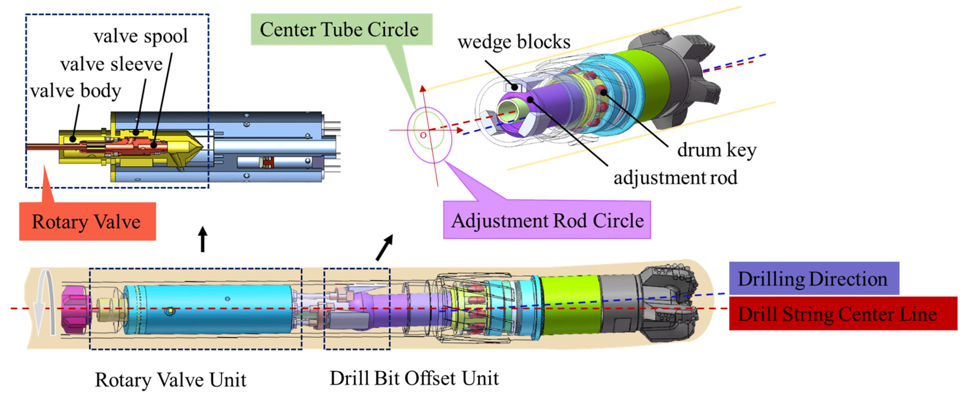
26] to further analyze the control characteristics and key influencing factors of the offset steering mechanism. The overall physical modeling architecture of the simulation model is shown in
Figure 7. The system comprises four core subsystems: a rotary valve model, a rotary valve control model, a pump-controlled displacement model, and a hydraulic cylinder and load model. The functions of each module are described as follows:
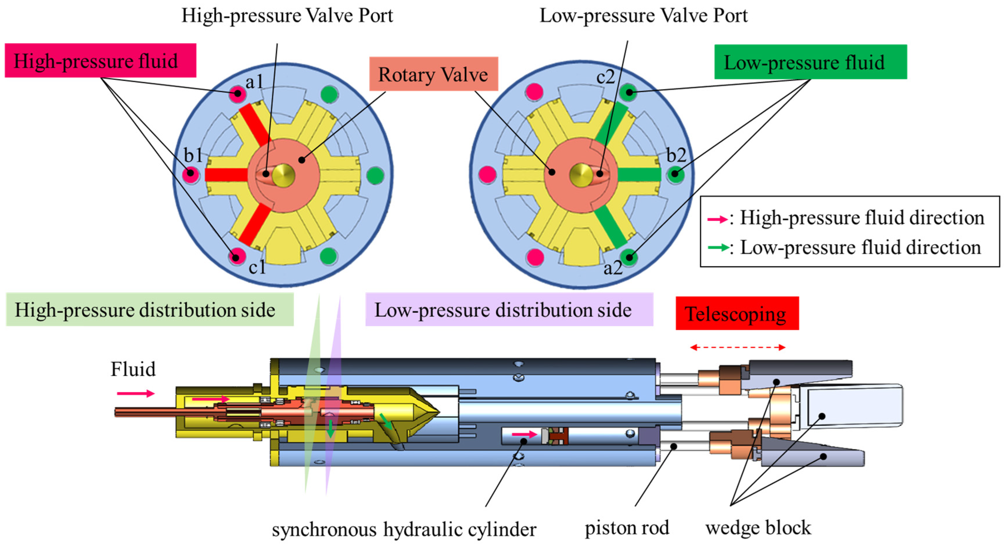
The rotary valve model simulates the hydraulic connection relationships and flow distribution characteristics of its internal flow distribution structure, and it is a key component for achieving pressure switching and flow regulation among multiple chambers. This model describes the on/off state between the fluid inlet port, fluid return port, and each working port via an equivalent valve port structure, and it dynamically adjusts the effective flow area in real time according to the rotational angle of the valve core to achieve flow distribution among the different working chambers. Its core function is to realize the distribution and switching of hydraulic energy among the actuation chambers, which is the basis for establishing system pressure and regulating flow.
The rotary valve control model simulates the control logic and actuation process for driving the rotary valve. Based on the input control signal (e.g., an electrical signal or a target angle command), this module outputs a driving signal through computation by the control algorithm to drive the rotary valve to reach the target position. The model is used to reflect the rotary valve’s response and control accuracy during actual control, which exerts a significant influence on the dynamic performance of the system.
The pump-controlled displacement model describes the flow regulation mechanism of a variable displacement pump and its coupling with system pressure. This module adjusts the pump’s output flow rate in real time in response to the control signal, thereby controlling the system flow and pressure to achieve an on-demand fluid supply. The dynamic characteristics of flow rate regulation are incorporated into the model, enabling the simulation results to reflect the energy-saving performance and pressure response of the pump-controlled system.
The hydraulic cylinder and load model is used to simulate the kinematic and dynamic characteristics of the actuation unit. The hydraulic cylinder model generates a driving force according to the pressure difference between the two chambers and calculates the piston motion state, taking into account the piston area, frictional resistance, and internal leakage; the load model describes the mass, damping, and stiffness characteristics of the external mechanical load. The coupling of these two models accurately reflects the changes in the actuation unit’s displacement, speed, and output force under different working conditions, providing an important basis for evaluating the system’s control accuracy and dynamic response performance.
The above four subsystems are coupled logically according to the power transmission path and signal control flow, and mechanical coupling relationships in actual operation, ensuring consistency between the simulation model and the physical test system. Among these, the rotary valve distribution model and the pump-controlled flow rate model are core modules for simulation analysis. Their modeling processes are carefully designed, incorporating the actual structural parameters and working principles of the prototype. The specific construction methods of their physical models will be elaborated below.
By clarifying the function of each module and the parameter matching characteristics, this simulation model is designed to meet the actual engineering requirements. Via simulation, the pressure response characteristics under different combinations of rotary valve speed and pump flow rate are analyzed to verify the rationality of the system’s flow distribution and pressure matching relationship. After unified calibration and parameter adjustment of each module, a numerical simulation analysis covering the entire working cycle can be conducted, providing a theoretical basis and data support for the physical prototype testing, system structural improvement, and control strategy optimization, thereby reducing test costs and improving the reliability of engineering applications.
- (1)
Simulation Model of the Flow Distribution System
Since no dedicated rotary valve model is available in the AMESim [
27] component library, a functionally equivalent spool valve module is adopted as a simulation substitute based on the actual working principle and circumferential flow distribution characteristics of the rotary valve [
28,
29]. As shown in
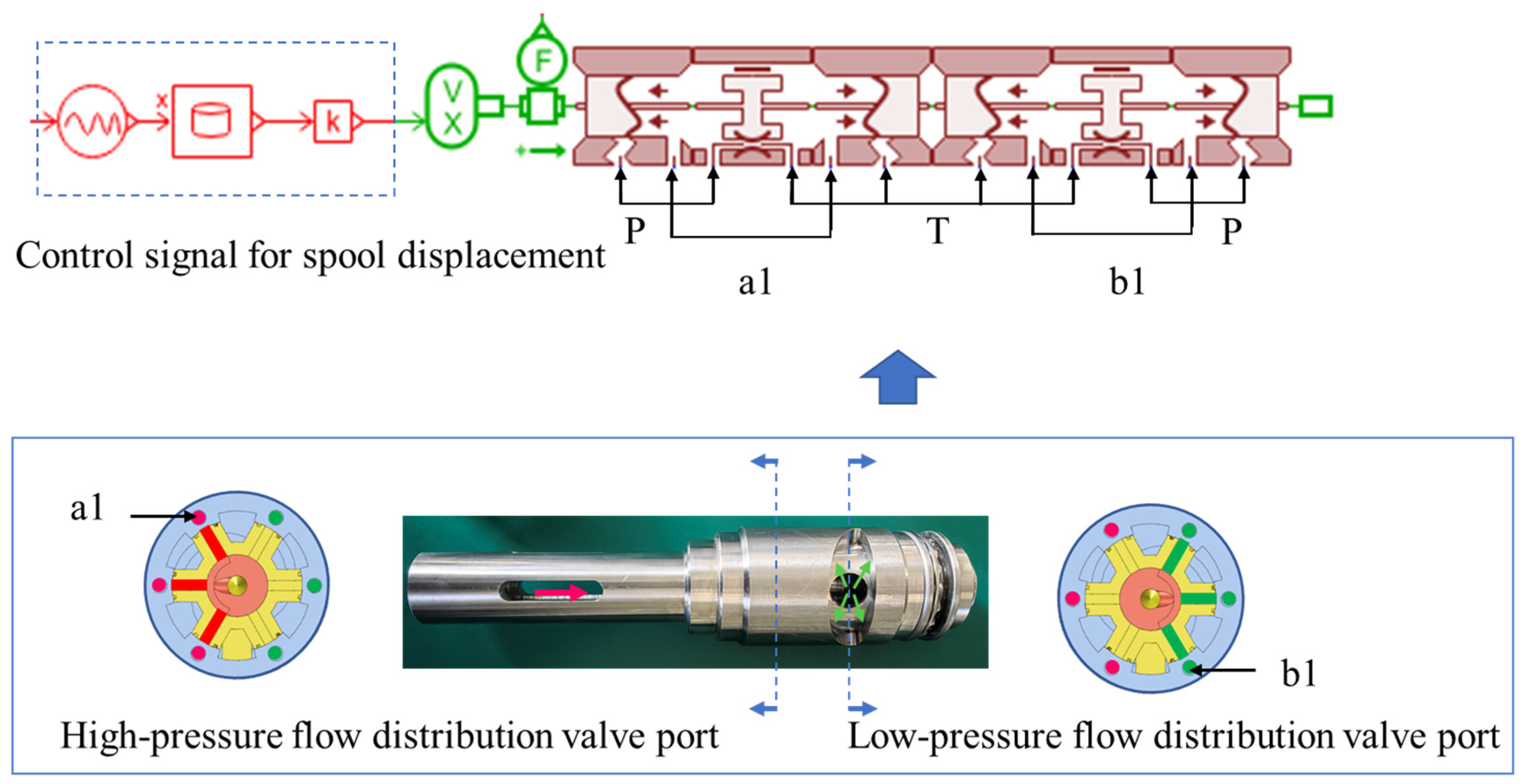
Figure 8, it is the equivalent modeling structure of a single group of flow distribution valves. During the modeling process, a single flow distribution unit is constructed by combining four custom valve port modules, which simulate the on/off switching logic relationships of the fluid inlet (port P), two working fluid ports (port a1, port b1), and the fluid return port (port T), respectively. The periodic angular displacement signal generated by motor rotation is converted into the reciprocating linear displacement input of the valve core, and through the coordinated adjustment of the valve core displacement control variable and the motor speed, the three sets of spool valves act in sequence following the 120° phase difference rule, thus realizing the functional equivalent simulation of the circumferential flow distribution process of the rotary valve.
To accurately replicate the flow distribution law of the rotary valve, the correlation data between valve core displacement and the effective flow area of the valve port is incorporated into the model, and the processes of valve port opening/closing and throttling area variation are described using a data-driven approach, thus achieving a refined characterization of the flow distribution characteristics. In the equivalent model, the P ports at both ends are fluid supply ports, and the entire flow distribution process follows the logic of alternating high-and low- pressure switching: when the high-pressure flow distribution valve port (a1) is connected to the fluid supply, the low-pressure flow distribution valve port (b1) is closed, and the fluid return path is opened at the same time; when the low-pressure flow distribution valve port (b1) is connected to the fluid supply, the high-pressure flow distribution valve port (a1) is synchronously closed and connected to the fluid return path. The above high- and low-pressure switching process constitutes a complete flow distribution cycle that corresponds exactly to one rotation of the motor, and its operating frequency is accurately controlled by the motor speed.
One reciprocating linear displacement cycle of the spool valve corresponds to driving the hydraulic cylinder piston to complete one reciprocating motion. Therefore, the motor speed directly determines the spool valve switching frequency, thereby determining the frequency and dynamic response characteristics of the hydraulic cylinder movement. Using this equivalent modeling method, the dynamic coupling between the rotary valve flow distribution process and the motion of the three hydraulic cylinder is simulated.
- (2)
Simulation Model of the Pump-Controlled System
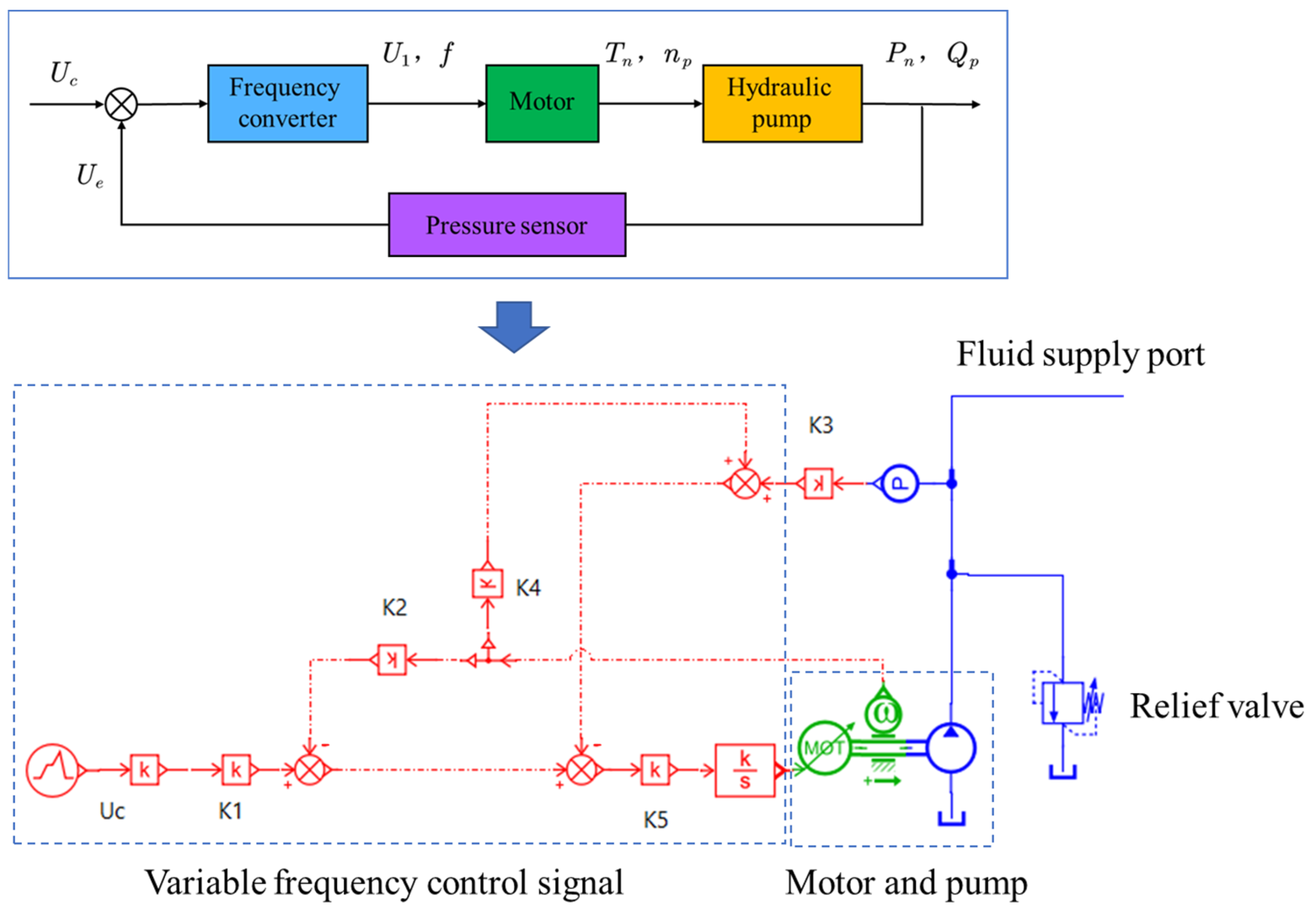
As the core control unit of the motor drive system, a simulation model of the frequency converter is established based on the voltage frequency (V/F) control principle, and an electromagnetic mechanical coupling model is established by combining the motor electromagnetic torque equation and the mechanical motion equation. During the modeling process, a linear mapping relationship between the 0–10 V standard analog input and the output frequency of 0~50 Hz is first established to convert the control voltage signal into a target frequency command; then, the functional relationship between the power supply frequency and the motor speed is established according to the asynchronous speed formula of the asynchronous motor: n ≈ 60f/p. Meanwhile, the electromagnetic torque slip characteristic equation and the mechanical dynamics equation (including moment of inertia, damping, and load torque) are incorporated to form a closed-loop coupling model. The main challenges in this modeling process lie in the frequency variation process, which is accompanied by the synchronous adjustment of the voltage amplitude. It is necessary to ensure that the magnetic flux remains approximately constant to avoid model distortion and that there is dynamic coupling between the motor speed and the main pump load torque; abrupt load changes will lead to motor speed fluctuations. Therefore, the model must reasonably introduce moment of inertia and damping parameters to ensure simulation stability and engineering consistency.
Therefore, a control structure is established based on the idea of vector minor closed-loop control, as shown in
Figure 9. A speed command is set at the input end, and a frequency control signal is generated after proportional–integral (PI) regulation; the frequency module outputs the corresponding alternating current (AC) frequency value, and the voltage amplitude is synchronously generated via the V/F proportional function. The motor module calculates the instantaneous rotational speed based on the output frequency and load torque. Then, a closed-loop adjustment is formed via speed feedback to achieve dynamic speed stabilization control. The motor output shaft is rigidly coupled with the main pump’s moment of inertia via a coupling model, so that the motor speed is directly mapped to the main pump speed, thereby completing the simulation of stepless speed regulation for the main pump. By setting different input voltage signals (0–10 V), the main pump speed can be continuously adjusted in the range of 0–1450 r/min, and load disturbances can be superimposed to analyze the system’s dynamic response characteristics under acceleration, deceleration, and impact load conditions.
3.3.2. Control Equations
- (1)
Control Equation of the Flow Distribution Valve
To ensure that the valve core opening shape meets the requirements for continuously variable dynamic output characteristics, this study optimizes the valve port shape parameters by combining the pressure–flow rate relationship with the feasibility of mechanical processing [
30]. The valve port shape of the flow distribution valve core must ensure that the effective flow area
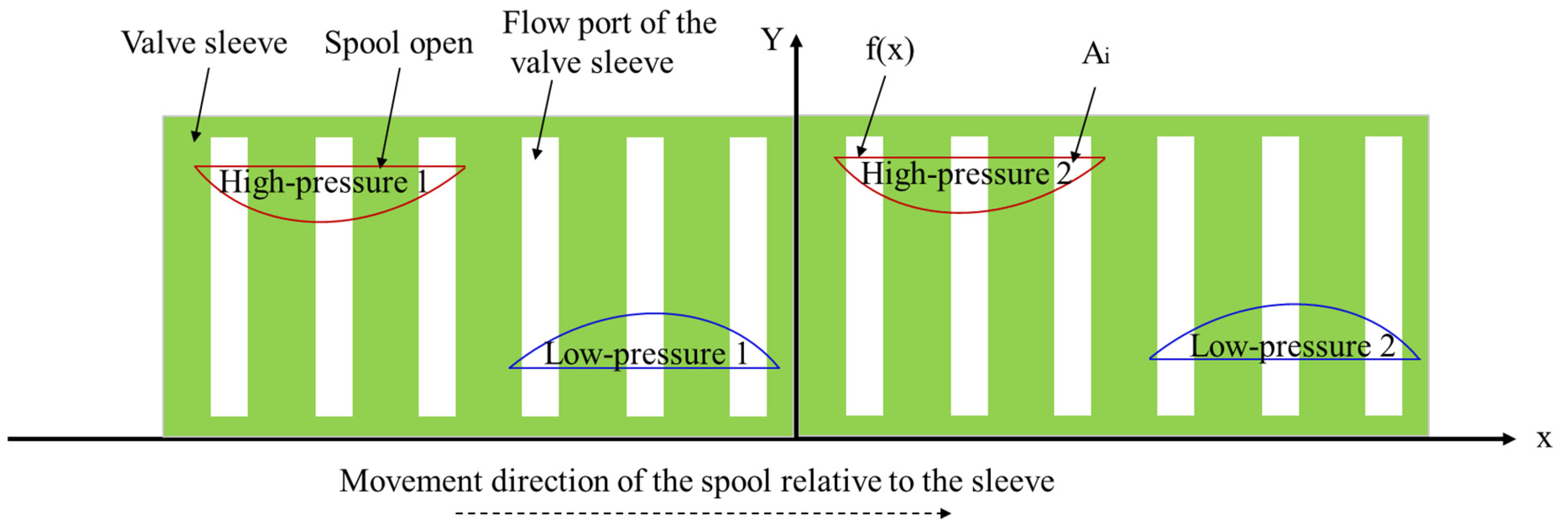
of the three hydraulic cylinder varies periodically, and its variation law must ensure that the piston displacement of the cylinder conforms to the simple harmonic motion law to ensure the stability and accuracy of the coordinated pushing of the wedge blocks. The geometric relationship of the circumferential rotation fit between the valve core and the valve sleeve is mapped to a plane, as shown in
Figure 10. The flow channel port of the valve sleeve is designed as a rectangular opening with a fixed width, and the valve core opening adopts a boundary function
envelope structure, which effectively adapts to the dynamic flow distribution requirements.
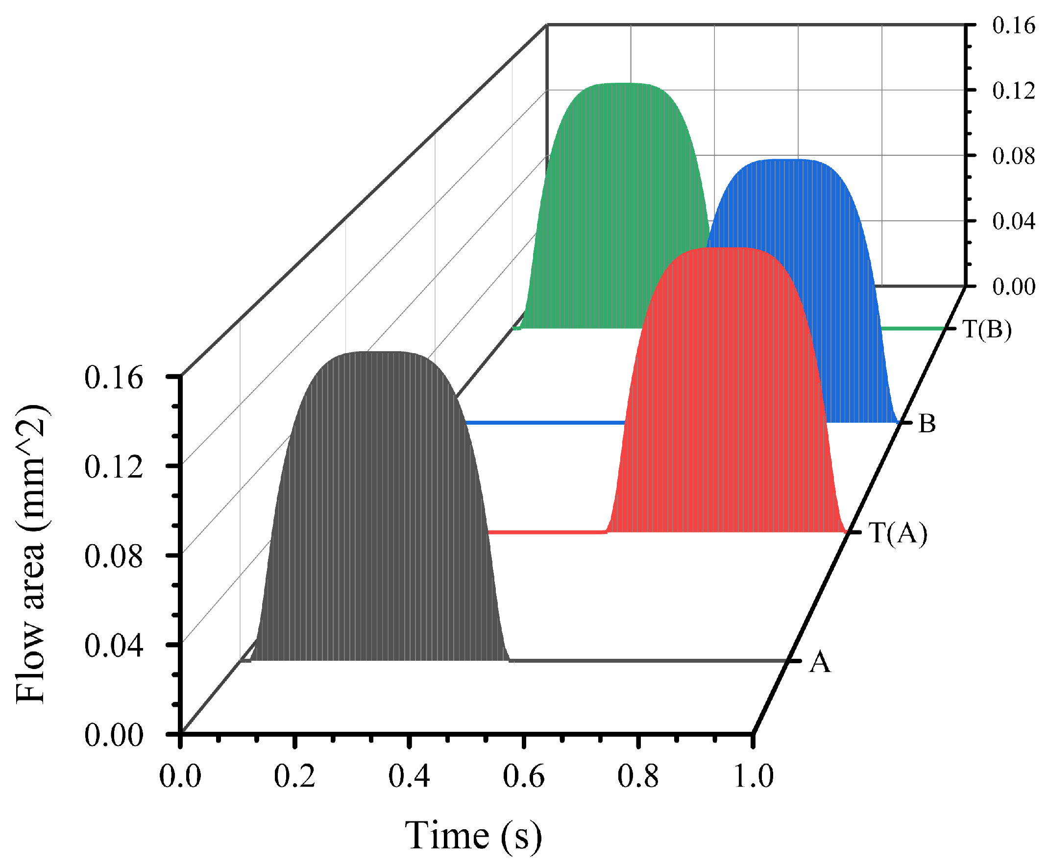
Based on the above valve port design and the working principle of rotary valve flow distribution, the positioning and sealing structures are designed to form an integrated valve assembly. The effective flow area corresponding to the valve core displacement is mapped to the geometric opening stroke, which is then converted into the area variation of the rotary valve port using a conversion relationship [
31]. The opening area is shown in
Figure 11.
- (2)
Control Equation of Variable Frequency Pump Control
To achieve accurate regulation of the rotary valve flow distribution, it is necessary to establish governing equations of the hydraulic system. The lumped-parameter method, implemented via the AMESim platform, is employed to solve these equations. The system hydraulics are governed by two fundamental conservation laws: the continuity equation (mass conservation) and the momentum equation (momentum conservation).
For each control volume, the net flow rate equals the rate of volume change plus the rate of pressure-induced compression due to fluid compressibility. The continuity equation in lumped-parameter form is given by:
The effective bulk modulus accounts for both fluid compressibility and the compliance of the hydraulic lines:
For flow through hydraulic elements (e.g., valves, orifices, and pipes), the pressure drop balances the inertial, viscous, and orifice effects. The momentum equation in lumped-parameter form is expressed as:
The relationship between the control voltage input to the frequency converter, the motor input voltage, and the flow rate [
32,
33,
34] allows the quantitative expression of flow rate control and can be derived as follows:
Therefore, the relationship between these two voltages (
) can be expressed by a proportional link. Based on the motor working principle, the electromagnetic torque of the three-phase AC asynchronous motor is given by [
35]:
When the slip ratio
is small, the formula can be simplified as:
Without considering low-voltage compensation, substituting the motor slip ratio into the above formula yields:
The torque balance equation of the motor system is:
After rearrangement, the equation is obtained as:
Calculation formulas for the axial piston pump [
36,
37]:
3.3.3. Parameter Setting
To systematically analyze the dynamic characteristics and steering performance of the three hydraulic cylinder synchronous steering control system under different operating parameters, the boundary conditions were established based on the overall physical model developed in the previous section. The inlet flow rate is set to 1.0, 1.25, and 1.5 L/s, corresponding to the pump flow rate, while the return pipeline pressure is maintained at a constant 0.1 MPa (atmospheric reference pressure). The flow passage area of the rotary valve is modeled using a data-driven function derived from the geometric opening curve, as shown in
Figure 11, with the discharge coefficient defined for the orifice. Simulations are performed using the AMESim standard solver (ODT) with the following settings: a variable-step ordinary differential equation solver employing the DASSL algorithm, a simulation duration of 12 s, and a data sampling interval of 0.001 s. The key assumptions of the numerical model are as follows.
Given the predominantly turbulent flow within the valve orifice, the drilling fluid is treated as a Newtonian fluid with a constant viscosity. Temperature variations are neglected, and both the bulk modulus and viscosity are assumed to be constant. Distributed parameter effects in the pipelines are approximated using lumped resistance, inertia, and capacitance elements. The fluid pressure throughout the simulation domain remains above the vapor pressure at all times. The valve core and hydraulic cylinders are regarded as rigid bodies with no elastic deformation, with only viscous friction considered for the cylinders and Coulomb friction neglected. All model parameters are derived from the actual experimental prototype, as shown in
Table 4. This framework enables the investigation of the effects of two key input parameters: rotary valve rotational speed and flow rate. Before solving the model, the coefficient values of the model equations are parameterized, as shown in
Table 4.
- (1)
Simulation of Three Hydraulic Cylinder Synchronous Characteristics Under Benchmark Working Conditions
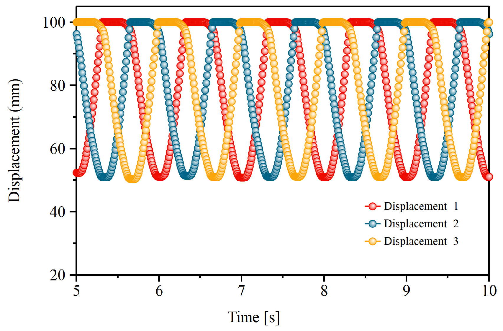
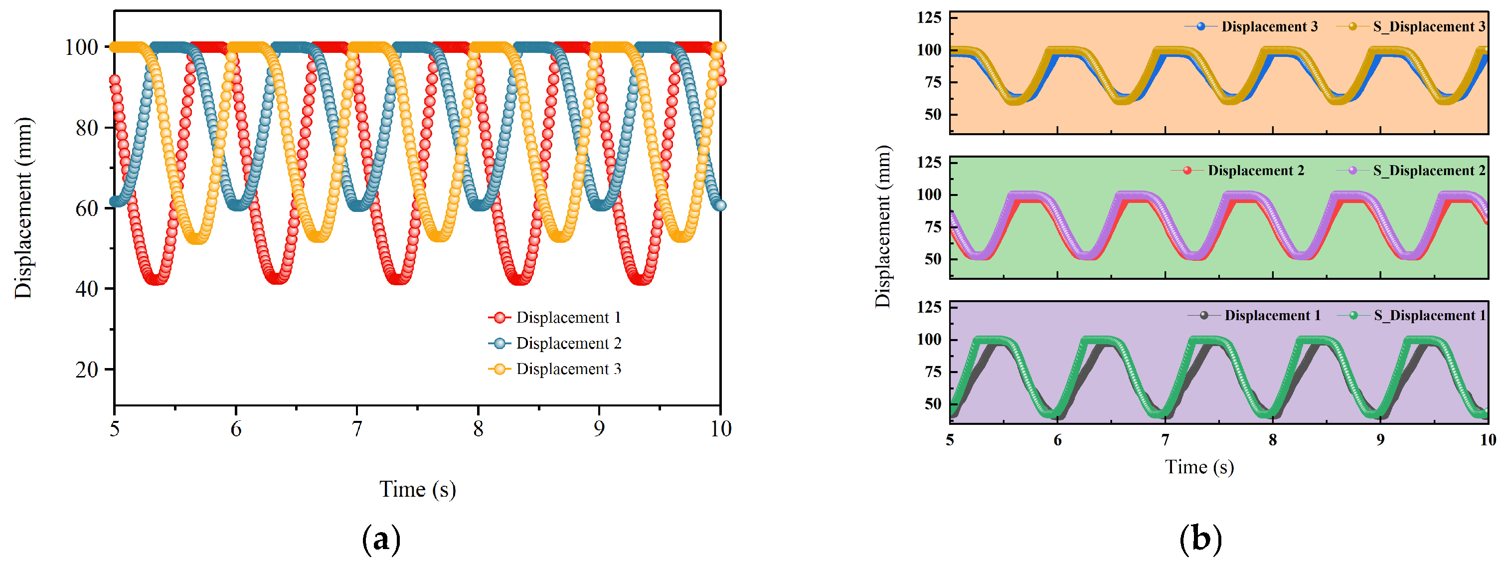
A fully symmetric reference working condition model for the three hydraulic cylinder is established under ideal consistent conditions. During the simulation, the structural, load, and control parameters of the three hydraulic cylinder are kept consistent to eliminate the influence of structural differences on the motion results, thus focusing on the system’s flow distribution mechanism and inherent power transmission characteristics. The system boundary conditions are uniformly set as follows: flow rate 1 L/s, rotary valve speed 90 rpm, rotary valve leakage gap 0.3 mm, and hydraulic cylinder piston diameter 38 mm. All the above parameters are derived from the structural design values and experimental calibration data of the actual test prototype and represent typical field operating conditions.
- (2)
Influence of Rotary Valve Speed on Steering Performance Under Fixed Displacement Condition
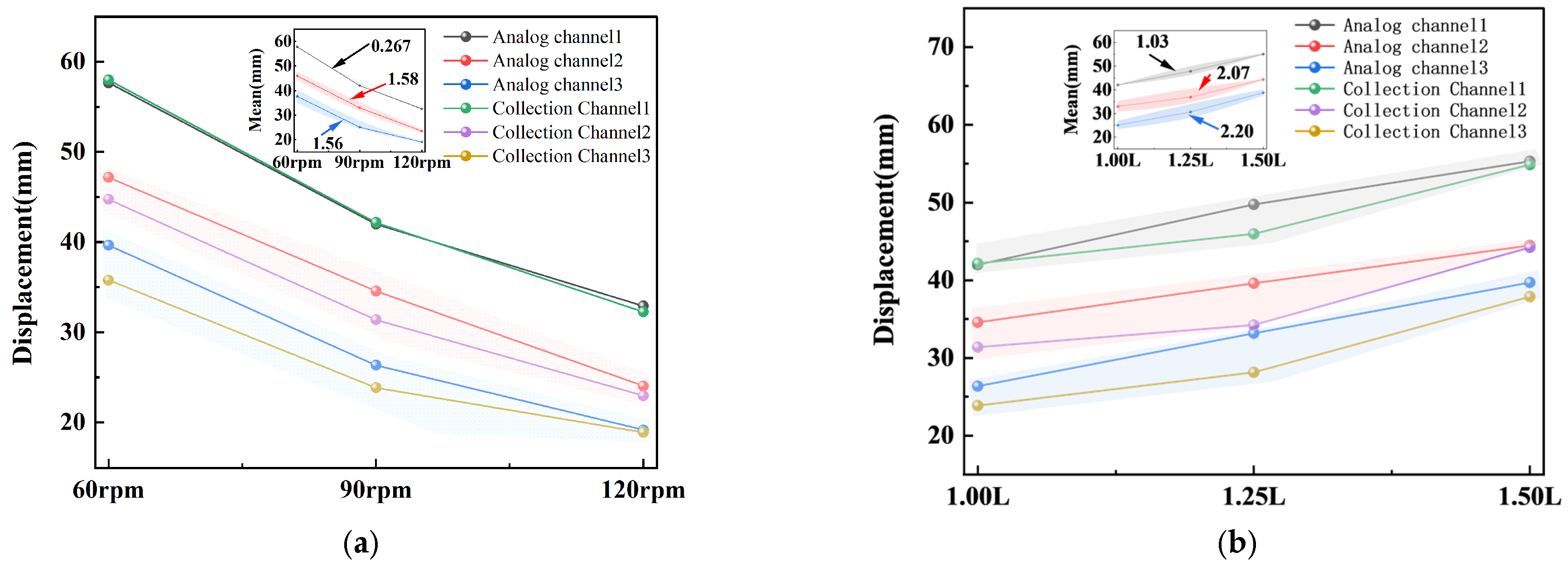
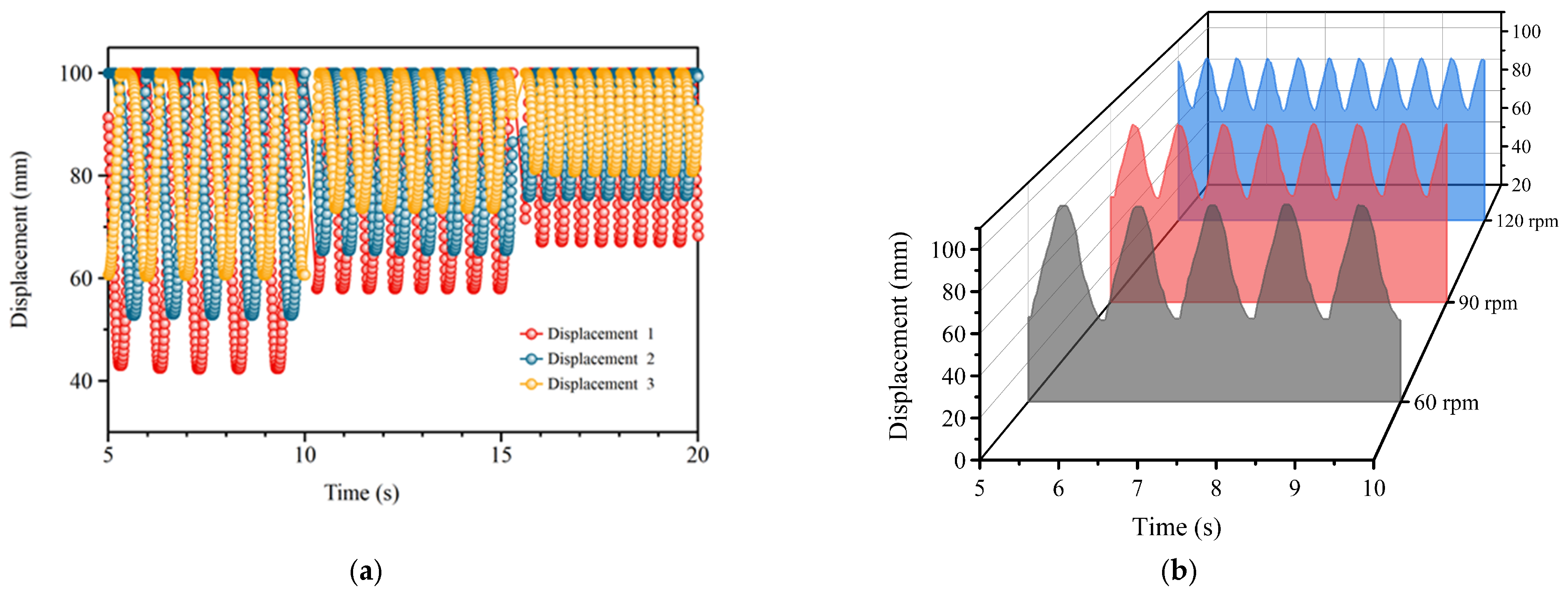
In the simulation, a constant flow input boundary condition is applied, and the flow rate is fixed at 1 L/s to isolate the effects of flow-related variables on the system response, thus allowing the analysis to focus on the rotary valve speed factor. The rotary valve speeds are set to 60 rpm, 90 rpm, and 120 rpm, respectively, covering low-frequency, medium-frequency, and high-frequency flow distribution intervals, which are consistent with the actual adjustability in field applications; the structural parameters of the three hydraulic cylinder are kept consistent, and displacement deviation working conditions are established by assigning different load values to simulate the uneven formation resistance during drilling. For each operating condition, displacement data from the steady-state operation stage are extracted, and the influences of start-up and transition processes are neglected. The displacement distribution characteristics and steering adjustment amplitudes of the three hydraulic cylinder under different speed conditions are compared, thus analyzing the influence law of flow distribution frequency variation on steering sensitivity and system stability.
- (3)
Influence of Flow Rate on Steering Performance Under Fixed Speed Conditions
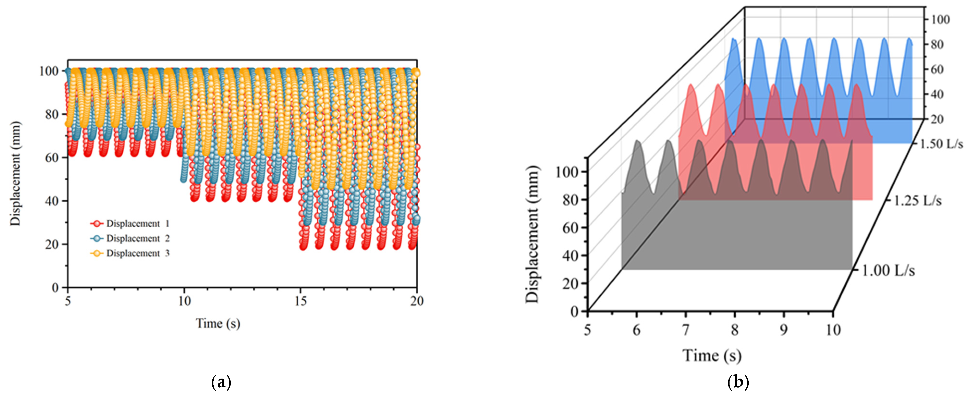
In the simulation, the flow distribution frequency is kept constant by fixing the rotary valve speed at 90 rpm, and a single-factor comparison study is conducted by varying the pump flow rate. The pump flow rates are set to 1 L/s, 1.25 L/s, and 1.5 L/s, respectively, with all other structural and control parameters kept unchanged to isolate the interference from the flow distribution frequency, ensuring the system response is solely affected by the flow rate variation. The above flow rate range covers the rated adjustment range of the main pump and typical field operating conditions for different drilling pressure and rotational speed requirements. Displacement data of the three hydraulic cylinder are extracted from the steady-state stage for each operating condition, and the variation trends of displacement deviation and steering amplitude under different flow rate input conditions are compared to evaluate the influence of flow rate adjustment on steering response capability and synchronization performance.




 and
and