Article

High-Efficiency Methanol Steam Reformer with Artificial Intelligence Complex System Response (AICSR) Optimized Pd–CuZn Catalysts for Portable Hydrogen Generation


1
Department of Engineering and System Science, National Tsing Hua University, Hshinchu 300044, Taiwan
2
Chemistry Department, National Tsing Hua University, Hshinchu 300044, Taiwan
3
Research Center for Applied Sciences, Academia Sinica, Taipei City 115201, Taiwan
*
Author to whom correspondence should be addressed.
Appl. Sci. 2026, 16(7), 3554; https://doi.org/10.3390/app16073554
Submission received: 6 March 2026 / Revised: 2 April 2026 / Accepted: 3 April 2026 / Published: 5 April 2026
(This article belongs to the Section Energy Science and Technology)

Abstract

We engineered a compact methanol steam reforming (MSR) system tailored to power a 1 kW High-Temperature Proton Exchange Membrane (HT-PEM) fuel cell. The unit integrates an evaporator, reformer, and burner within a cylindrical titanium-alloy vacuum flask to minimize parasitic heat loss. Guided by an Artificial Intelligence Complex System Response (AICSR) framework, we developed a segmented catalyst architecture that positions an optimized Pd/ZnO/Al2O3 catalyst downstream of a commercial Cu–Zn catalyst bed. This spatial configuration reduces palladium consumption by >50% while maintaining a hydrogen generation rate of 8000 sccm at 250 °C. During a 40 h stability test, the system exhibited a low deactivation rate of 0.235% h−1, with methanol conversion decaying gradually from 98.1% to 88.7%. The downstream PdZn intermetallic phase actively promoted the water–gas shift (WGS) reaction, restricting CO concentration to an average of 3.9% (minimum 2.5%). Achieving a system thermal efficiency of 88.589% and a 20 min startup time, this design validates AI-assisted spatial catalyst distribution as a highly viable strategy for compact hydrogen generation.

Graphical Abstract

1. Introduction

Global energy infrastructures remain heavily reliant on fossil fuels, which account for nearly 60% of oil consumption and 30% of total energy supply, particularly within the transportation sector [1,2]. This persistent dependence accelerates greenhouse gas emissions and exacerbates anthropogenic climate change [3]. Consequently, hydrogen provides a viable alternative as a zero-emission energy carrier characterized by high thermodynamic conversion efficiency.
Compared to conventional fuels, hydrogen delivers distinct thermodynamic advantages. Hydrogen-fueled combustion engines and fuel cells achieve efficiencies of up to 60% and 65–70%, respectively, far outperforming the 35–38% baseline of modern thermal power plants [4,5,6]. Integrating hydrogen fuel cells with electric powertrains yields overall system efficiencies of 40–60%, vastly exceeding the 11–25% limit typical of internal combustion gasoline vehicles [7,8]. Because hydrogen electrochemical oxidation yields only water vapor, it intrinsically eliminates CO2, NOx, and particulate emissions at the point of use [9]. Coupled with production pathways utilizing renewable resources, hydrogen stands as a foundational element in transitioning toward net-zero energy infrastructures [10,11,12].
Large-scale hydrogen deployment remains structurally constrained by prohibitive production costs and the lack of viable storage and distribution infrastructures [13]. Methanol mitigates these logistical bottlenecks by serving as a highly practical liquid hydrogen carrier. Exhibiting a volumetric energy density of 15.8 MJ/L (4.39 kWh/L)—orders of magnitude higher than ambient hydrogen (0.01 MJ/L)—methanol enables stable, ambient-condition storage and transport [14,15]. Furthermore, its lack of carbon–carbon bonds and high hydrogen-to-carbon ratio facilitate efficient catalytic reforming while thermodynamically suppressing coke formation. Coupling a methanol steam reformer (MSR) with downstream fuel cells inherently circumvents the membrane crossover degradation endemic to direct methanol fuel cells (DMFCs). This indirect reforming configuration delivers electrochemical performance analogous to pure-hydrogen-fed proton exchange membrane (PEMFC) or phosphoric acid fuel cell (PAFC) systems [16,17].
Methanol steam reforming (MSR) distinguishes itself among reforming pathways by delivering a maximum theoretical yield of three moles of H2 per mole of methanol [18,19,20]. Relative to methanol decomposition (MD) and partial oxidation (POM), MSR intrinsically maximizes hydrogen production while minimizing CO selectivity, satisfying the stringent gas purity criteria of CO-intolerant fuel cells [16]. Sustaining this optimal balance of high conversion and trace CO formation, however, conventionally dictates substantial catalyst loadings operating at low space velocities.
Despite the thermodynamic advantages of MSR, catalyst durability and CO selectivity remain primary operational bottlenecks. Conventional Cu/ZnO-based systems exhibit high intrinsic activity under mild conditions. Within these architectures, ZnO acts as a structural and textural promoter, enhancing copper dispersion, inhibiting thermal sintering, and improving hydrogen selectivity by suppressing CO formation [21,22]. Under practical thermal cycling, however, these copper-based catalysts remain highly susceptible to sintering-induced deactivation. Concurrently, they generate elevated CO concentrations that threaten the integrity of downstream fuel cell anodes. While integrating structural promoters like Al2O3 improves metal dispersion and thermal stability [23], these modifications only partially mitigate the inherent degradation mechanisms. Recent advancements in Cu-based architectures include the deployment of CeO2–Al2O3 supports [24], inverse ZrO2/Cu interfaces for near-zero CO emission [25], and morphologically tailored sol–gel Cu/ZnO/Al2O3 networks [26]. Beyond copper chemistries, palladium-based catalysts offer a structurally robust alternative, demonstrating superior resistance to both thermal sintering and sulfur poisoning while drastically reducing CO selectivity [27]. Targeted synthesis and activation protocols yield highly dispersed Pd nanoclusters that maximize both methanol conversion and hydrogen yield. Mechanistic investigations attribute this CO suppression to Pd–Zn intermetallic phase evolution and the modulation of formaldehyde intermediate pathways, establishing clear design principles for low-CO reforming [28,29]. The prohibitive cost of noble metals, however, structurally constrains their widespread commercialization, necessitating advanced strategies to minimize Pd loading without compromising catalytic efficacy.
Beyond catalyst formulation, reactor architecture fundamentally dictates the heat and mass transfer efficiencies of MSR systems. Modular and stacked configurations minimize thermal diffusion lengths and maximize internal heat recuperation. These geometries compress reactor volume, yielding rapid thermal responses, homogenized temperature gradients, and compact hydrogen yields. Demonstrating this, Sahlin et al. engineered a 5 kW integrated MSR–HT-PEM fuel cell unit utilizing a dual-loop thermal management strategy [30]. During startup, a burner-driven thermal oil loop rapidly heated the reformer, while a secondary cooling loop simultaneously preheated the evaporator and fuel cell stack. At steady state, this secondary loop extracted excess exothermic heat from the fuel cell to drive the endothermic evaporator, structurally preventing stack overheating.
Scaling down to microreactor dimensions further amplifies these mass-transfer advantages. Zheng et al. tailored a hybrid catalyst-support architecture, achieving complete methanol conversion while strictly suppressing CO selectivity [31]. For kW-scale systems, Zhang et al. implemented an aggressive waste-heat recovery network, stabilizing integrated operations and elevating overall thermal efficiency [32]. Exploiting stacked geometries, Qian et al. successfully decoupled the thermal zones for the reformer (290 °C) and the HT-PEM fuel cell (170 °C) [33]. By integrating proportional-integral-derivative (PID) control, their system suppressed thermal oscillations, achieving steady-state operation within a 17 min startup window and guaranteeing long-term durability.
Within the reactor architecture, thermal uniformity directly dictates both reaction stability and reformate quality. Ha et al. [34] systematically demonstrated the profound impact of spatial catalyst distribution on burner thermal profiles. When catalytic beds were concentrated near the inlet, rapid localized exothermic reactions induced severe wall overheating and thermal gradients, restricting fuel conversion to 91%. Conversely, shifting the catalyst toward the outlet prolonged gas–catalyst contact time, homogenizing the thermal profile (maximum ΔT = 40 °C) and elevating conversion to 98.2%. Applying these spatial engineering principles, we implemented a cloverleaf-shaped microchannel flow field [35] featuring an asymmetric 30:70 inlet-to-outlet catalyst mass ratio. This targeted distribution homogenized the internal thermal field and suppressed reformate CO concentration from 9.23% to 7.58%, directly upgrading overall hydrogen purity.
Beyond chemical formulations, microchannel and porous architectures offer profound structural optimizations for reformers [36,37,38]. These geometries inherently intensify mass and heat transfer, suppressing CO formation and elevating overall system efficiency. Concurrently, evaporator geometry dictates latent heat utilization; maldistribution of multiphase fluids severely degrades performance [39], necessitating rigorous optimization of inlet/outlet placements and distributor plates [40,41,42]. Diverging channel configurations effectively mitigate two-phase flow instabilities, stabilizing evaporation dynamics [43]. Synthesizing these engineering principles, Harkou et al. [44] established that reactor configuration is equally decisive as catalyst selection, identifying microreactor designs as critical pathways toward compact, high-efficiency reforming. At the catalytic level, Cu-based and PdZn systems present contrasting operational advantages: Cu-based materials deliver exceptional intrinsic activity, whereas PdZn intermetallics excel in thermal stability and CO suppression [45,46]. Moreover, strong metal-support interactions (SMSI) fundamentally govern MSR activity and intermediate CO pathways [47]. To navigate these multidimensional material and geometric variables, machine-learning frameworks have revolutionized predictive modeling and catalyst screening [48,49]. This data-driven paradigm directly aligns with our implementation of an Artificial Intelligence Complex System Response (AICSR) framework [50] to systematically optimize Pd loading and spatial distribution.
Despite significant advances in catalyst development and microchannel reactor design, a critical gap remains in their system-level integration for kW-scale portable applications. Existing studies are largely fragmented, focusing either on the intrinsic kinetics of Pd-based catalysts or on reactor-level transport phenomena, with limited understanding of how localized thermal gradients interact with degradation mechanisms in segmented catalyst beds. Moreover, the trade-off between CO suppression and noble metal cost remains unresolved, as no established strategy exists to determine the minimal effective Pd loading for stable operation. To address these challenges, this work engineers a compact, integrated methanol steam reforming (MSR) system tailored to power a 1 kW high-temperature proton exchange membrane (HT-PEM) fuel cell. Housed within a cylindrical titanium-alloy vacuum flask to minimize parasitic heat loss, the unit couples an evaporator, a microchannel reformer, and a catalytic burner. A cloverleaf-shaped flow geometry was implemented to homogenize the internal thermal field, while an Artificial Intelligence Complex System Response (AICSR) framework was deployed to optimize Pd loading, defining a segmented spatial architecture comprising an upstream Cu–Zn bed and a downstream Pd/ZnO/Al2O3 catalyst. This spatial engineering reduces noble metal consumption by over 50% while structurally suppressing CO formation. Operating at 250 °C, the system delivers 8000 sccm of hydrogen. During a 40 h stability test, methanol conversion decayed gradually from 98.1% to 88.7%, yielding a low deactivation rate of 0.235% h−1, while the downstream PdZn intermetallics maintained an average CO concentration of 3.9%. These results demonstrate the synergistic integration of AI-guided catalyst spatial distribution and compact thermal management, providing a practical pathway toward stable and efficient portable hydrogen generation.

2. Design of the Integrated Methanol Steam Reforming System

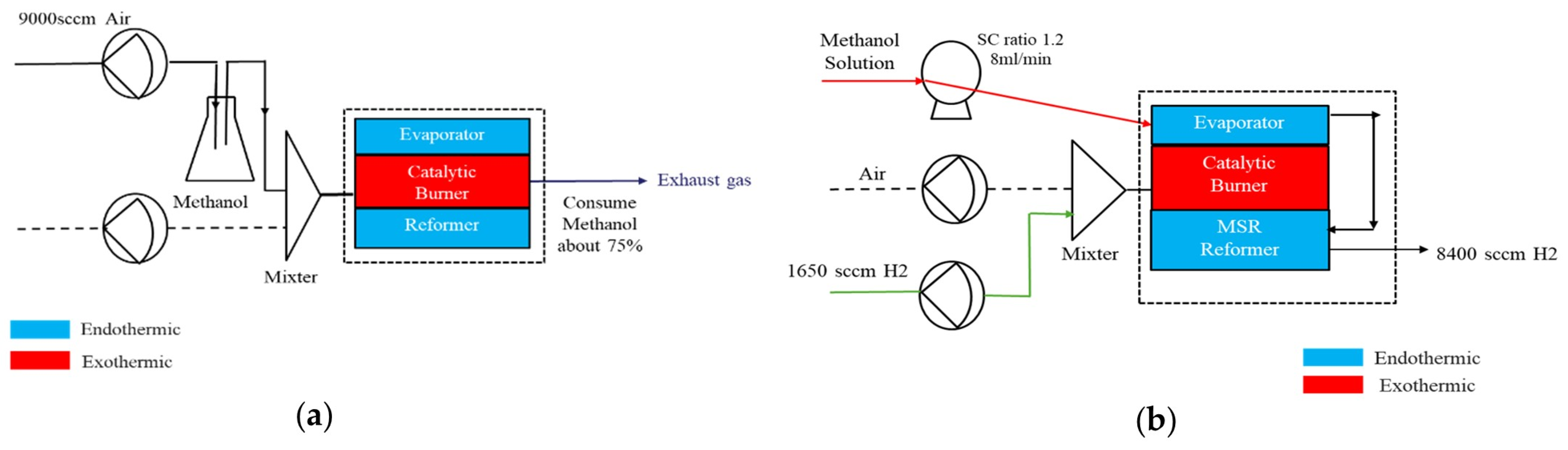
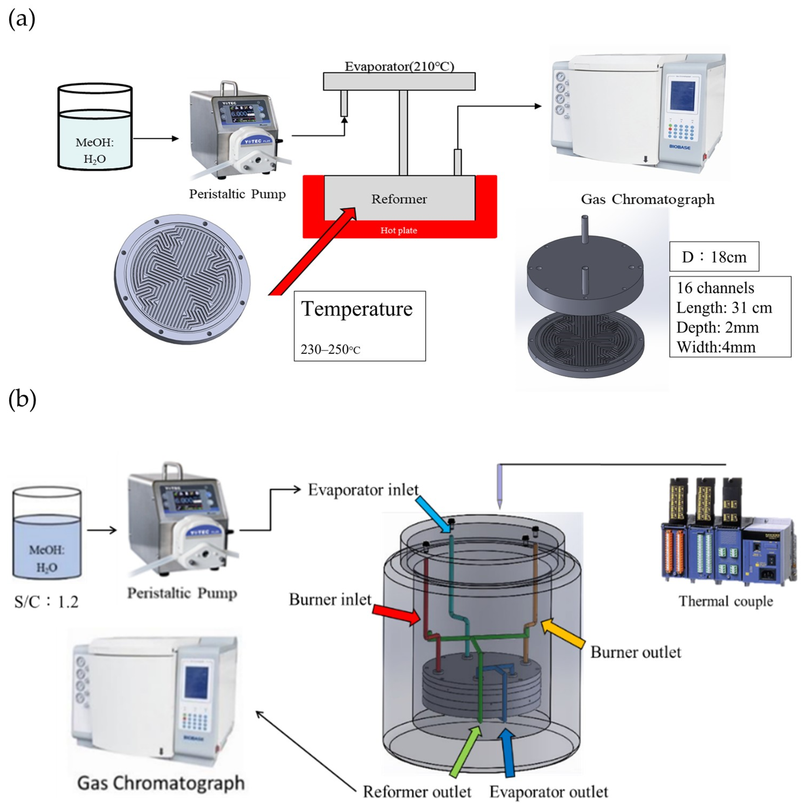
The schematic diagram of the portable methanol steam reforming (MSR) system is shown in Figure 1a. The integrated system comprises a reformer, catalytic burner, and evaporator (Figure 1a,b). Detailed design, fabrication, and testing procedures for each unit are provided in Supplementary Sections S1–S3.
The principal thermochemical pathways governing the system—comprising methanol steam reforming, alongside the catalytic combustion of both methanol and hydrogen—are defined as follows:
Methanol steam reforming (endothermic):
C H 3 O H + H 2 O 3 H 2 + C O 2 H 298 O = + 49.4   k J · m o l 1
Methanol combustion (exothermic):
C H 3 O H + 1.5 O 2 C O 2 + 2 H 2 O   H 298 O = 631.3   k J · m o l 1
Hydrogen combustion (exothermic):
H 2 + 0.5 O 2 H 2 O   H 298 O = 285.5   k J · m o l 1
During the startup phase (Figure 1a), a mixing chamber pre-blends methanol vapor with 9000 sccm of cylinder-supplied air before introduction into the catalytic burner. The ensuing exothermic combustion elevates the system temperature to 250 °C, supplying sufficient thermal energy to drive both the evaporator and the segmented catalytic reformer.
Transitioning to steady-state operation (Figure 1b), a peristaltic pump injects a methanol–water mixture—maintained at the thermodynamically optimal steam-to-carbon (S/C) molar ratio of 1.2—into the evaporator. The resulting vapor phase enters the reformer, generating a reformate stream composed of H2, CO2, trace CO, and unreacted methanol. To sustain the endothermic reforming process and maintain thermal equilibrium, the burner switches to combusting 1650 sccm of hydrogen, supplemented by 9000 sccm of air (equivalence ratio Φ = 1.6).
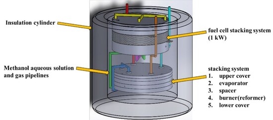
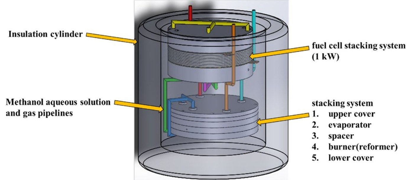
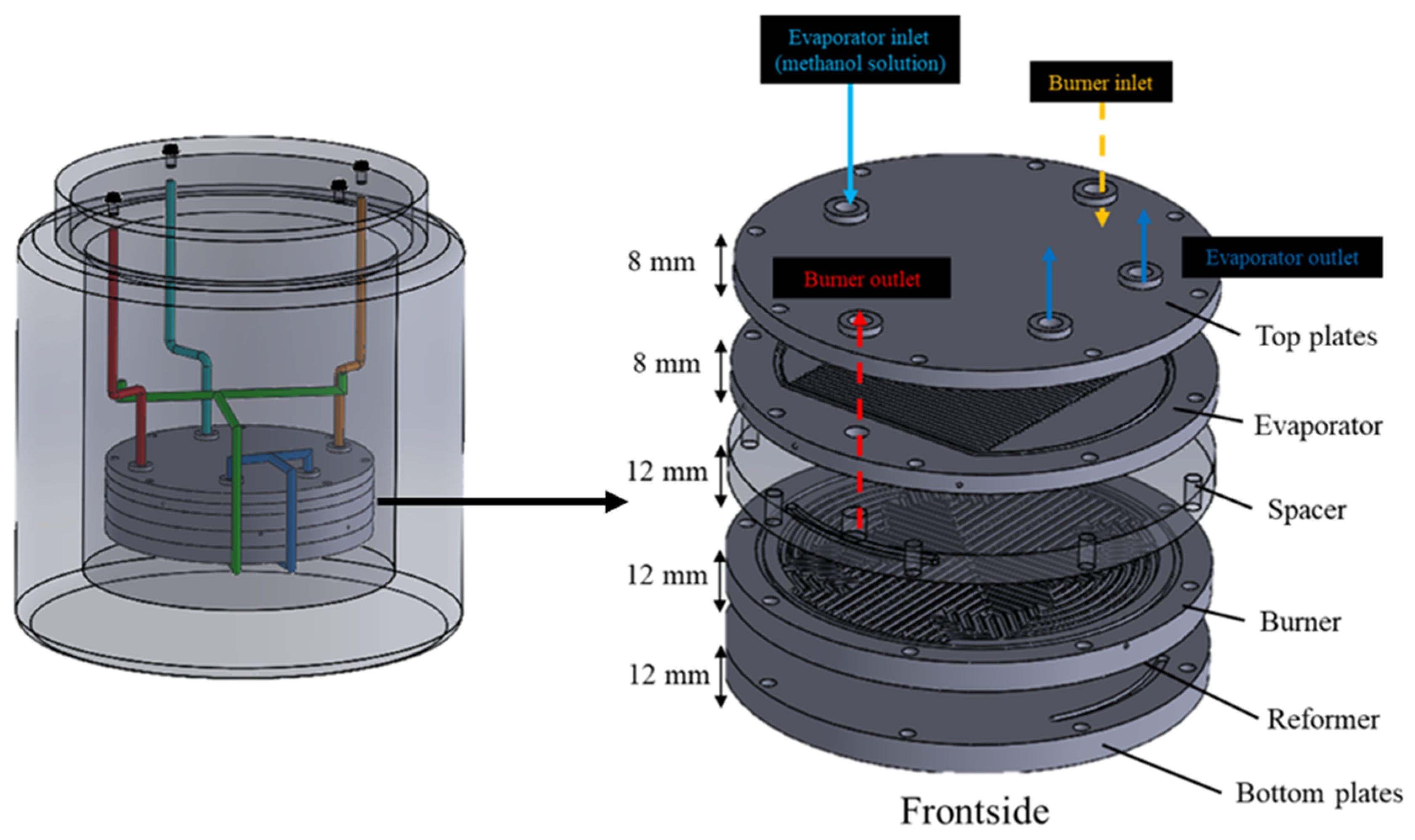
Figure 2 illustrates the stacked system architecture. The assembly descends from an upper end plate through the evaporator, a thermal insulation layer, the catalytic burner, the reformer, and a lower end plate. Crucially, the insulation layer restricts parasitic heat transfer from the burner to the evaporator, preventing fluid boiling instabilities. This vertically integrated topology minimizes thermal diffusion lengths, homogenizes temperature gradients, and maximizes catalytic efficiency. Torque-controlled bolting, coupled with intercalated graphite gaskets (Shen-Shih Enterprise Co., Ltd., New Taipei City, Taiwan), ensures uniform pressure distribution and absolute gas-tight sealing. Thermocouples continuously recorded the operational temperatures of the respective plates, while tee-joint sampling ports at the burner and reformer exhausts facilitated precise gas composition analysis.

3. Experimental

3.1. Artificial Intelligence Complex System Response (AICSR)

To systematically optimize both catalyst formulations and operational parameters, we implemented the Artificial Intelligence Complex System Response (AICSR) [51] framework. This platform operates as an interpretable, low-data machine learning architecture, integrating strategic parameter sampling with deterministic mathematical modeling.
We established the boundaries of critical input parameters based on strict thermodynamic and operational constraints. To efficiently map this high-dimensional space, we deployed an Orthogonal-Array-Composite-Design (OACD). This sampling strategy drastically reduces the required experimental trials while rigorously preserving parametric diversity. In heterogeneous catalysis, minimizing the dataset is a physical necessity rather than a mere statistical convenience; it effectively suppresses the time-on-stream bias induced by continuous catalyst deactivation mechanisms, such as thermal sintering and active-site agglomeration.
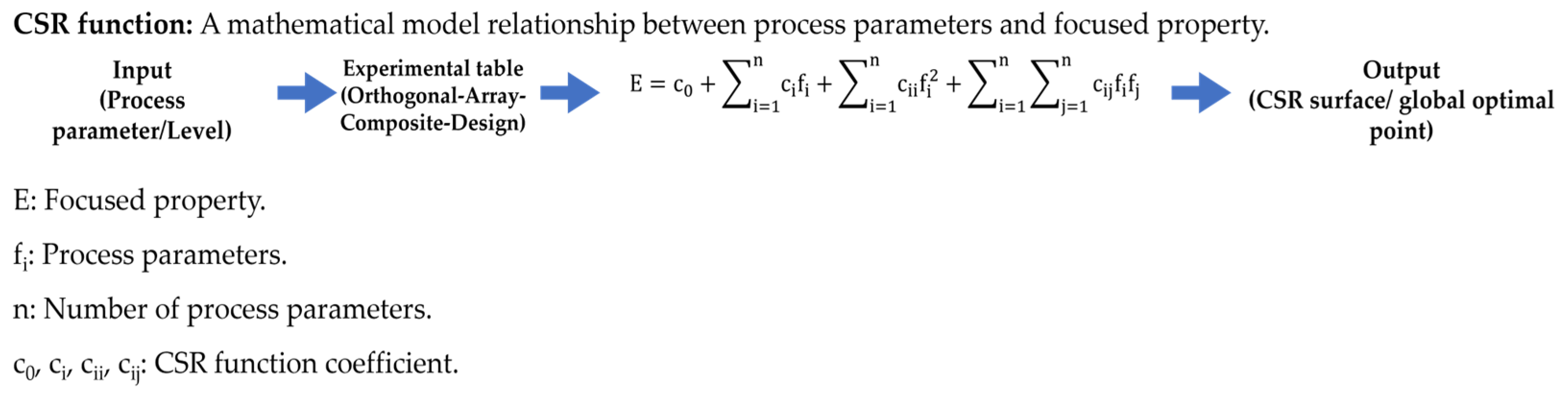
Key catalytic responses, including methanol conversion, hydrogen yield, and CO concentration—were explicitly mapped using the Complex System Response (CSR) equation:
E ( c ) = x 0 + i = 1 P x i c i + i = 1 P x i i c i 2 + i < j x i j c i c j
where E represents the catalytic response, and c i denotes the normalized input variables. The coefficients are obtained via least-squares regression over the OACD dataset.
Within this formulation, each term carries explicit physical significance:
  • x i : linear contribution of individual parameters to the system response
  • x i i : second-order intra-component effects, reflecting nonlinear constraints such as adsorption saturation or thermodynamic limits
  • x i j : cross-interaction terms, capturing synergistic or antagonistic effects between variables (e.g., metal–support interactions or bimetallic coupling)
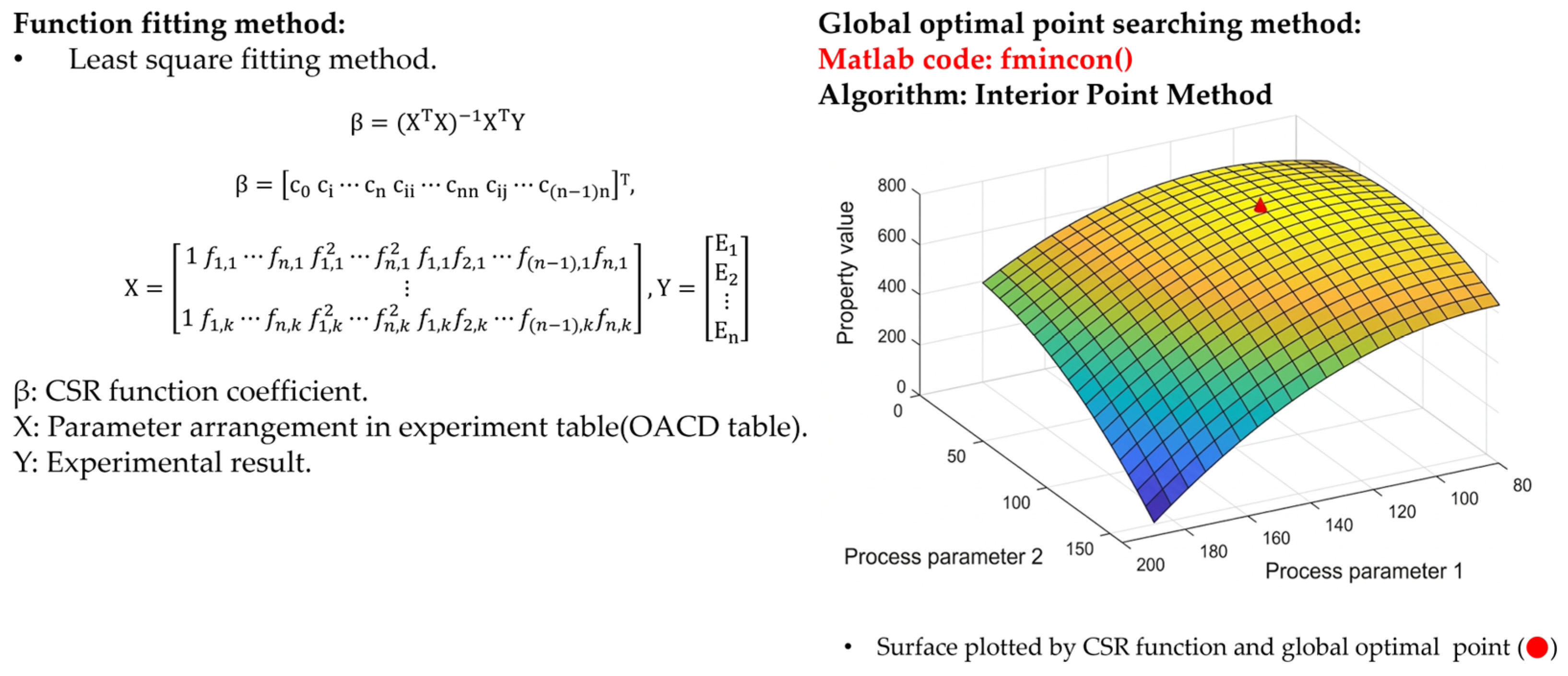
Rather than relying on localized statistical interpolation typical of conventional methodologies, this CSR architecture serves as a global, structured mapping of nonlinear physicochemical interactions. Finally, a constrained interior-point optimization algorithm was deployed across this deterministic landscape to identify the absolute global optimal parameter sets that maximize hydrogen production while structurally suppressing CO formation. By supporting iterative data integration, the AICSR framework enables adaptive, physics-informed refinement of the catalytic system (Figure 3).

3.2. Catalyst Preparation

To systematically evaluate thermal and kinetic performance, two distinct catalyst systems were prepared and investigated:
  • Cu–Zn catalyst: Commercial Cu–Zn catalyst was ground, sieved, and separated into two particle-size fractions, The large catalyst refers to particles with diameters ranging from 420 to 590 μm, whereas the Small catalyst corresponds to particles within the range of 177–250 μm. for thermal and kinetic evaluation.
  • Pd catalyst: Based on AICSR-optimized composition, Al2O3 and ZnO powders were impregnated with Pd(NO3)2 solution. The mixture was dried at 60 °C (8 h), calcined at 400 °C (4 h), and reduced under H2 at 250 °C (24 h), yielding Pd/ZnO/Al2O3.
  • The preparation routes for both catalysts are summarized in Figure S4.
  • For comparative reactor evaluation, we engineered two dual-bed catalyst configurations, each maintaining a total mass of 50 g packed in a strictly segmented 9:1 upstream-to-downstream mass ratio (45 g:5 g):
  • Configuration A (Particle Size Effect): An upstream primary bed (45 g, 90 wt%) of large Cu–Zn particles (420–590 μm) coupled with a downstream secondary bed (5 g, 10 wt%) of small Cu–Zn particles (177–250 μm)
  • Configuration B (Noble Metal Promotion): An identical upstream primary bed (45 g, 90 wt%) of large Cu–Zn particles, coupled with a downstream secondary bed (5 g, 10 wt%) of the synthesized Pd/ZnO/Al2O3 catalyst (177–250 μm).
As illustrated in Figure S6, the 45 g primary bed was positioned at the reactor inlet, while the respective 5 g secondary bed was anchored at the outlet. This decoupled spatial arrangement explicitly isolates the effects of geometric particle sizing (Configuration A) and secondary noble-metal catalysis (Configuration B) on overall methanol steam reforming efficiency and CO suppression.

3.3. Reformer Performance Testing

To evaluate standalone reformer performance, we metered a liquid methanol–water mixture—fixed at a steam-to-carbon (S/C) molar ratio of 1.2—into an evaporator maintained at 210 °C. The fully vaporized feed subsequently entered the catalytic reformer, operating within a targeted temperature window of 250 °C. We quantified the reformate gas composition (H2, CO2, CO, and residual CH3OH) using an online gas chromatograph (GC-1000 equipped with a thermal conductivity detector, China Chromatography Co., Ltd., New Taipei City, Taiwan) calibrated against certified standard gas mixtures. These continuous compositional measurements enabled the precise derivation of critical kinetic metrics, notably dynamic methanol conversion and CO concentration. Figure 4a illustrates the comprehensive testing apparatus alongside the cloverleaf-shaped microchannel flow field, a structural geometry specifically engineered to homogenize internal thermal gradients.

3.4. Integrated System Testing

The complete MSR system (burner–evaporator–reformer) was tested in two phases:
  • Startup Phase: To initiate the system, we introduced a premixed methanol/air stream into the catalytic burner. We sustained this exothermic combustion until the internal thermocouples registered steady-state target temperatures of 250 °C for the reformer and 170 °C for the evaporator. Concurrently, we sampled the burner exhaust via gas chromatography (GC) to monitor combustion completeness.
  • Steady State: Upon reaching the target thermal gradients, we initiated the reforming sequence by continuously pumping the liquid methanol–water feed into the evaporator. To autonomously maintain system thermal equilibrium, the burner transitioned to combusting a hydrogen/air mixture. We continuously routed the reformer effluent through the online GC to precisely quantify steady-state hydrogen yield and trace CO concentration.
The testing procedure and simulated operating conditions are illustrated in Figure 4b.

3.5. Data Analysis

The performance of the reformer and integrated system was quantified using the following indicators:
  • Methanol conversion (XMeOH)
X M e O H = F M e O H , i n F M e O H , o u t F M e O H , i n × 100 %
where F M e O H , i n and F M e O H , o u t represent the inlet and outlet methanol flow rates, respect tively.
  • Hydrogen yield (YH2)
Y H 2 = F H 2 , o u t 3 F M e O H , c o n s u m e d × 100 %
where F H 2 , o u t denotes the outlet hydrogen flow rate, and F M e O H , c o n s u m e d represents the amount of methanol consumed during the reaction. Theoretically, each mole of methanol can produce three moles of hydrogen according to the overall methanol steam reforming reaction. Therefore, the theoretical hydrogen amount can be expressed as:
F H 2 , t h e o r e t i c a l = 3 × F M e O H , c o n s u m e d
representing the fraction of theoretical maximum hydrogen production achieved.
  • CO selectivity (SCO)
S C O = y C O y C C + y C O 2
where y C O 2 and y C O represent the respective mole-fractions (or molar flow fractions) of CO2 and CO in the reaction products. indicating the proportion of CO relative to total carbon oxides in the reformate.
  • Energy efficiency (η)
η = L H V H 2 F H 2 , o u t L H V M e O H F M e O H , i n × 100 %
where L H V H 2 and L H V M e O H are the lower heating values of hydrogen and methanol, respectively (kJ/mol or kJ/kg); F H 2 , o u t is the molar flow rate of hydrogen actually produced (mol/s); and F M e O H , c o n s u m e d is the molar flow rate of methanol consumed in the reaction (mol/s).
Gas compositions were quantified via GC using calibration curves for H2, CO2, CO, and CH3OH. All data points represent the average of at least three independent runs, and standard deviations are reported where appropriate.

4. Results

4.1. AICSR-Based Optimization of Pd Catalyst Parameters

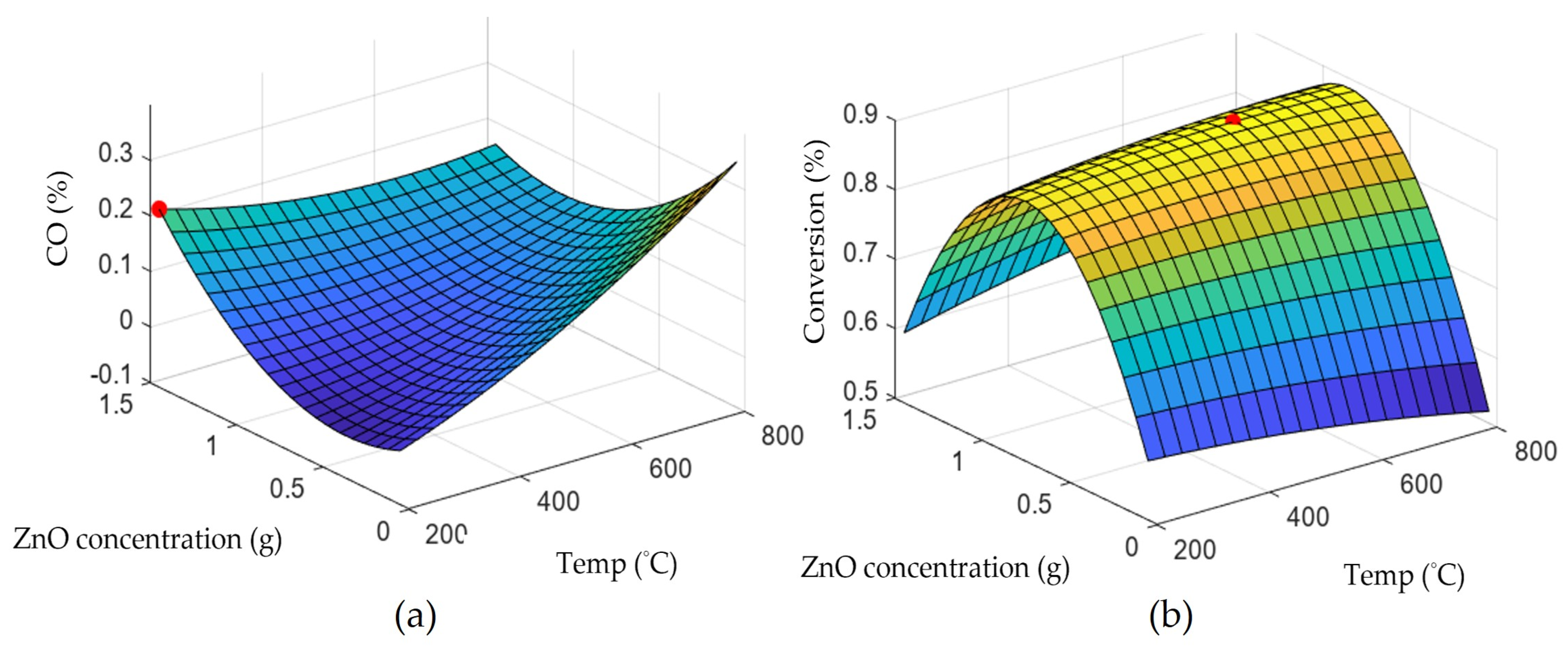
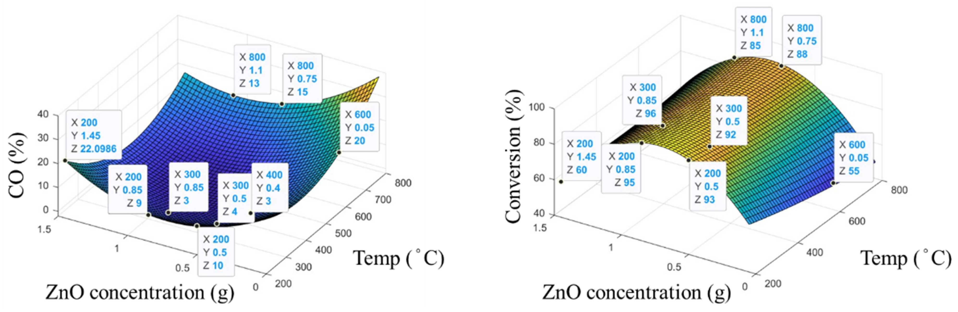
We utilized the Artificial Intelligence Complex System Response (AICSR) platform to systematically optimize the synthesis parameters of the Pd/ZnO/Al2O3 catalyst. Specifically, we screened ZnO concentration and calcination temperature as the primary independent variables. The platform initially generated an orthogonal array of five representative parameter sets, which we experimentally evaluated for methanol conversion and CO selectivity. Iterating these empirical responses back into the AICSR algorithm yielded the initial three-dimensional (3D) response surface plots (Figure 5). This mathematical mapping delineated the non-linear interactions between the synthesis variables and catalytic performance, with comprehensive quantitative data provided in Table S1.
These initial response surfaces indicated that calcination temperatures between 200 °C and 300 °C maximized methanol conversion while suppressing CO formation. To further refine the predictive model within this targeted domain, the AICSR algorithm proposed several candidate synthesis protocols. We experimentally validated four boundary combinations and merged this verification data to construct the updated 3D response surfaces (Figure 6). The augmented model rigorously confirmed the initial predicted trends (Table S2).
Extracting from this refined dataset, the AICSR framework predicted two global optima for the catalyst synthesis parameters. Subsequent experimental execution of these two protocols yielded catalytic performances that tightly aligned with algorithmic predictions, consistently achieving methanol conversions > 95% alongside CO concentrations < 3% under screening conditions (Tables S3 and S4). These tight correlations definitively validate the AICSR framework as a highly efficient, data-driven methodology for accelerating targeted catalyst design.

4.2. Characterization of Pd-ZnO/Al2O3 Catalyst

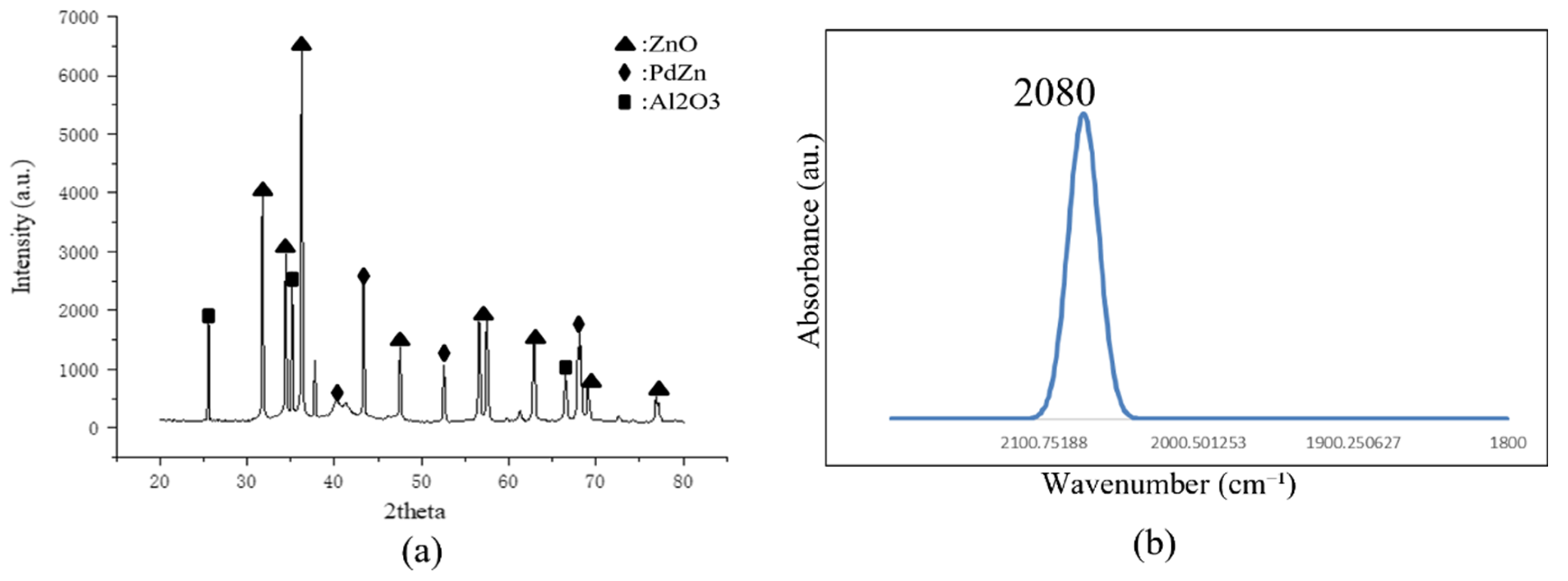
We investigated the bulk and surface configurations of the synthesized Pd/ZnO/Al2O3 catalyst utilizing X-ray diffraction (XRD) and CO-diffuse reflectance infrared Fourier transform spectroscopy (CO-DRIFTS). The XRD diffractograms (Figure 7a) display distinct reflections matching the structurally ordered PdZn intermetallic phase, with an absence of metallic Pd or PdO peaks. This structural profile indicates the extensive incorporation of Pd atoms into the ZnO lattice during reduction, yielding a homogeneous PdZn alloy without macroscopically segregated metallic domains.
Thermodynamically, this PdZn intermetallic architecture fundamentally alters the reaction pathway. The alloying process modifies the electronic valence state of surface Pd sites, favoring the selective scission of C–H and O–H bonds while preserving C–O bonds. Concurrently, the lattice-confined PdZn phase actively drives the downstream water–gas shift (WGS) reaction—consuming intermediate CO to generate CO2—while inherently resisting nanoparticle sintering under operating thermal stresses.
Complementary CO-DRIFTS spectra (Figure 7b) directly probe this modified surface electronic landscape, revealing a single linear CO adsorption band centered at 2080 cm−1 and a complete absence of bridging CO configurations. Relative to the linear CO stretching frequencies typical of pure Pd (<2070 cm−1) or conventional PdZn (~2075 cm−1), this localized blue shift signifies pronounced geometric isolation of surface Pd atoms. Zinc electronically perturbs these isolated Pd sites, actively attenuating the π-back-donation from Pd d-orbitals into the CO 2π* antibonding orbital. This diminished back-donation weakens the CO binding energy, directly mitigating CO poisoning and optimizing the activation barrier for intermediate conversion.
Importantly, the minor blue shift compared to theoretical PdZn benchmarks suggests the persistence of trace metallic Pd microdomains. This localized surface heterogeneity physically corroborates the residual CO formation observed during integrated reactor testing (minimum CO concentration of 2.5%). Ultimately, the synergy between bulk PdZn alloying (Figure 7a) and surface electronic modulation (Figure 7b) mechanistically underpins the sustained methanol conversion and the low thermal deactivation rate (0.235% h−1) established in our long-term system evaluations. PdZn alloy formation (XRD, Figure 7a) and surface Pd isolation/electronic modification (DRIFTS, Figure 7b) underpins the observed high methanol conversion, enhanced H2 selectivity, and improved catalyst stability. Further optimization of reduction conditions and surface alloying is expected to further suppress residual CO formation and maximize hydrogen purity.

4.3. Effect of Catalyst Configuration on Reformer Temperature Distribution and Performance

To explicitly isolate the influence of spatial catalyst arrangement on reaction dynamics, we comparatively evaluated Configuration A (pure Cu–Zn beds) and Configuration B (Cu–Zn upstream, Pd/ZnO/Al2O3 downstream) using the established 9:1 segmented packing architecture. We mapped macroscopic thermal gradients continuously via multi-point thermocouples and infrared (IR) thermography (Figure 8).
Operating at comparable mean bed temperatures (253.4 °C for Configuration A and 251.7 °C for Configuration B), the dual-bed configurations yielded distinctly divergent thermal and selectivity profiles. The baseline Configuration A exhibited a broader thermal variance with a standard deviation of 5.2 °C, alongside a high methanol conversion of 97.5% and a substantial reformate CO concentration of 6.7%. This indicates that while the upstream Cu–Zn agglomerates effectively drive the primary MSR pathway, they lack the intrinsic catalytic activity to propagate the secondary water–gas shift (WGS) reaction, leading to downstream CO accumulation.
Conversely, the Pd-promoted Configuration B significantly enhanced macroscopic thermal uniformity, compressing the temperature standard deviation to 3.1 °C. This stabilization physically demonstrates that the segmented architecture effectively mitigates localized thermal gradients across the reactor. Concurrently, Configuration B sustained a comparable fuel conversion of 96.4% while drastically suppressing the terminal CO concentration to a minimum of 2.5% (a 62.7% relative reduction). By catalytically consuming intermediate CO via the downstream WGS pathway, this targeted spatial configuration maximizes hydrogen purity and satisfies the stringent operational criteria of HT-PEM fuel cells.

4.4. Long-Term Stability Test and Performance Validation of Pd Catalyst

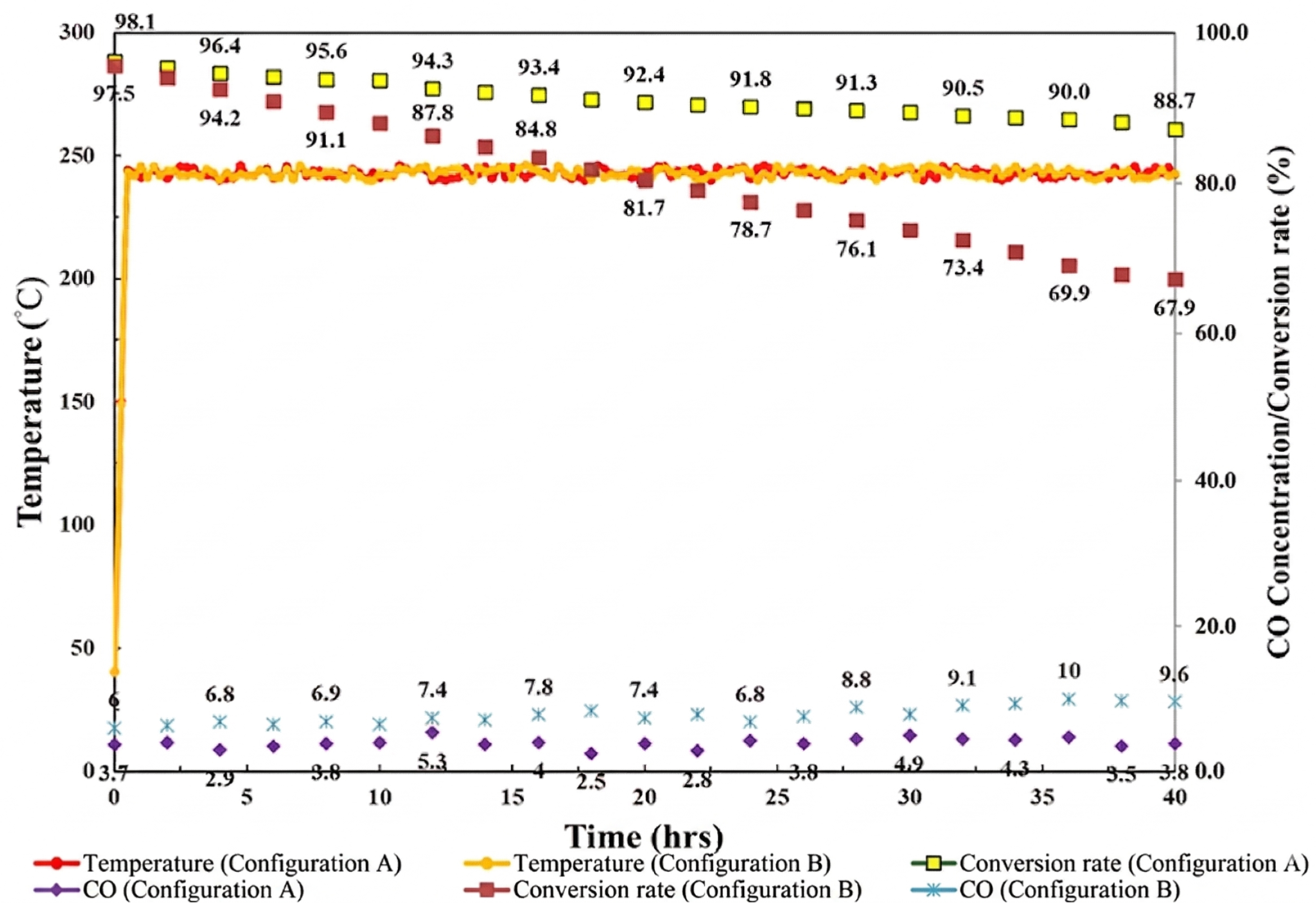
We evaluated the operational stability of the integrated reforming system under a continuous 1 kW-equivalent load over a 40 h time-on-stream (TOS) (Figure 9). To benchmark the AI-optimized formulation, we compared the baseline Configuration A (upstream large Cu–Zn coupled with downstream small Cu–Zn) against the Pd-promoted Configuration B (upstream large Cu–Zn coupled with downstream Pd/ZnO/Al2O3).
As summarized in Table 1, the configurations exhibited distinct stability profiles despite identical liquid feed rates (8 mL min−1). Configuration A underwent rapid deactivation driven by prolonged thermal and chemical stress; methanol conversion decayed from 97.5% to 67.9%, representing a deactivation rate of 0.74% h−1. Concurrently, terminal CO concentrations escalated to 6–10%. This degradation exposes the inherent structural vulnerability of conventional copper-based catalysts to thermal sintering and active site poisoning in high-throughput environments.
In contrast, the Pd-promoted Configuration B demonstrated superior catalytic robustness. Initial methanol conversion reached 98.1% and decayed to 88.7% over 40 h, yielding a deactivation rate of 0.235% h−1—a threefold improvement over the baseline. The downstream PdZn intermetallic phase restricted CO formation to an average of 3.9% (minimum 2.5%), preserving the reformate quality required for high-temperature polymer electrolyte membrane (HT-PEM) fuel cell integration. Configuration B also sustained a stable hydrogen flow rate of 8000 sccm. These findings confirm that AI-guided segmented Pd integration mitigates rapid catalyst degradation and optimizes continuous hydrogen yield for portable power generation.

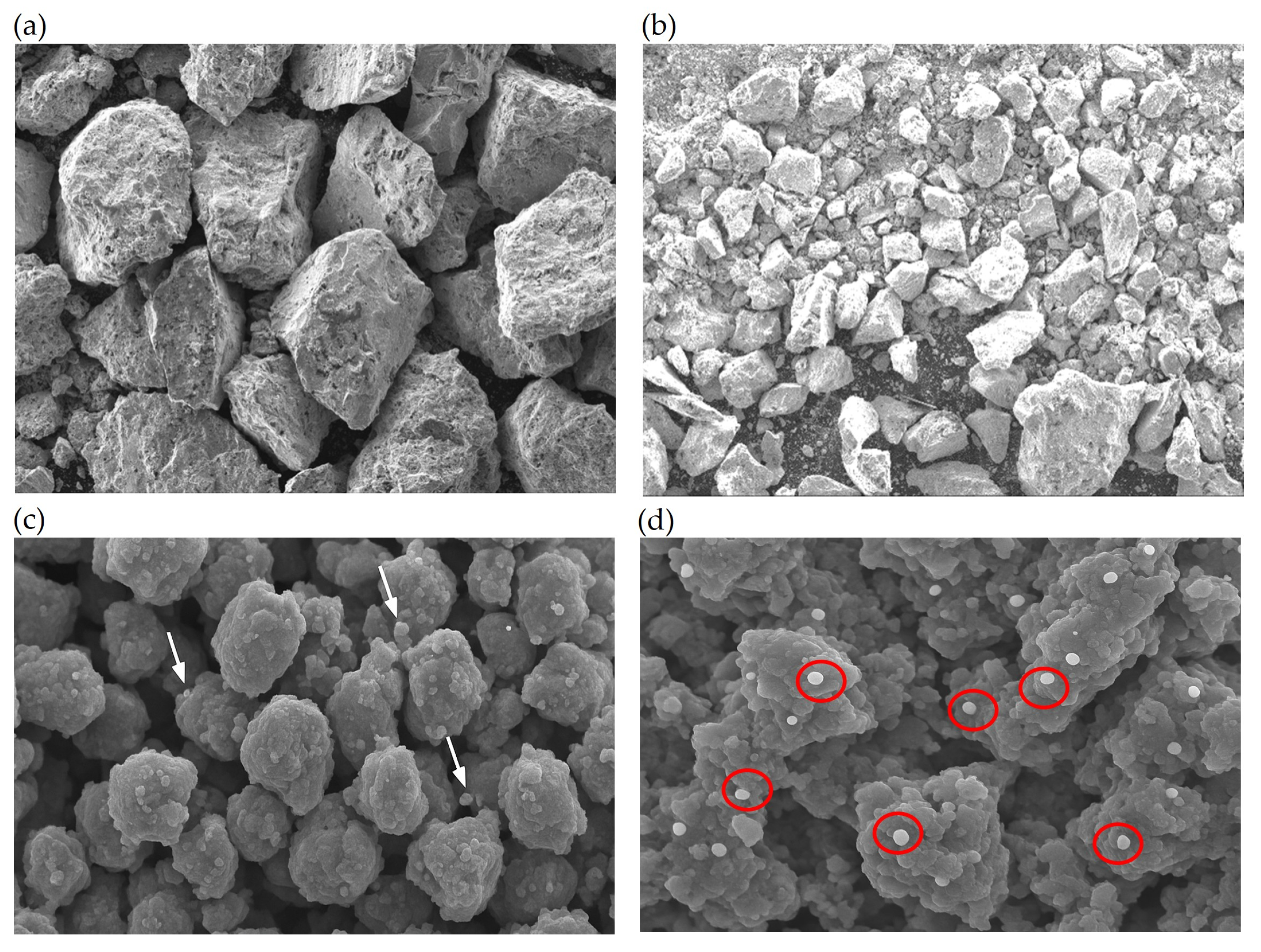
4.5. SEM Analysis of Fresh and Spent Catalysts

Figure 10 shows the SEM images of the Cu-Zn and Pd catalysts before and after 40 h of methanol steam reforming reaction. The Cu-Zn catalyst exhibited obvious particle fragmentation after reaction, with the particle size decreasing from 420–590 µm to 200–300 µm, indicating poor structural stability under the reaction conditions. In contrast, the Pd catalyst showed only slight agglomeration and surface reconstruction, while its porous morphology was largely preserved. These results suggest that the Pd catalyst had better resistance to sintering and structural degradation than the Cu-Zn catalyst during prolonged operation.

4.6. Thermal Efficiency Analysis During Steady-State Operation

The overall system efficiency is defined as the fraction of chemical energy recovered relative to the total fuel input (methanol + burner fuel).
Hydrogen-based efficiency
Considering only hydrogen as the useful product, the system achieves:
η H 2 = Q H 2 Q M e O H , i n + Q f u e l , i n
This corresponds to an efficiency of 83.5%, indicating effective conversion of input fuel into target hydrogen energy.
Total energy retention efficiency
When including unreacted methanol as recoverable chemical energy:
η s y s , t o t a l = Q H 2 + Q u n r e a c t e d M e O H Q M e O H , i n + Q f u e l , i n
The efficiency increases to 88.5%, reflecting the high overall energy retention within the system.
Reformer Thermal Utilization Efficiency
The reformer efficiency evaluates the effectiveness of thermal coupling between the burner and the reaction zone:
η r e f = Q f e e d e n t h a l p y + Q r e a c t i o n Q f u e l , i n
The calculated value is 94.0%, demonstrating highly efficient heat transfer within the reactor.
While idealized adiabatic systems may approach ~97%, the experimentally obtained value provides a realistic assessment. The remaining ~6% heat loss is primarily attributed to exhaust gas enthalpy, indicating minor but unavoidable thermal leakage.
Global Enthalpy Balance and Heat Loss
From a system-wide perspective, the total enthalpy input is:
  • Q i n , t o t a l = 1722.5   W
The net heat loss is:
Δ Q l o s s = Q i n , t o t a l Q o u t , t o t a l
resulting in:
  • ΔQloss = 197.5 W (~11.5%)
This level of heat loss highlights structural and insulation limitations, suggesting that further improvements in thermal management (e.g., insulation design or heat recovery) are necessary for enhanced system efficiency. The detailed energy balance of the MSR system is summarized in Table 2.

5. Discussion

The integrated methanol steam reforming (MSR) system developed in this study demonstrated robust performance in terms of stability, hydrogen production capacity, and thermal efficiency. A key factor was the incorporation of the AICSR-optimized Pd/ZnO/Al2O3 catalyst in the rear section of the reformer, which markedly improved internal temperature uniformity and minimized local hot spots. Thermal imaging confirmed a narrow temperature distribution, with a standard deviation of only 3.1 °C, reflecting enhanced thermal management and reaction stability.
Long-term testing under a 1000 W operating condition further highlighted the advantages of the Pd catalyst configuration. The measured deactivation rate was only 0.235%/h, substantially lower than the 0.74%/h observed with a conventional Cu–Zn catalyst arrangement. Throughout 40 h of continuous operation, methanol conversion consistently exceeded 95%, while the CO concentration averaged 3.91%, with a minimum of 2.5%. These results confirm the Pd catalyst’s ability to suppress CO formation, which is critical for downstream fuel cell integration, while simultaneously extending catalyst durability.
Thermal efficiency analysis reinforced these findings. The overall MSR system efficiency, calculated based on the total chemical energy input from methanol and the burner fuel, was approximately 88.5%, considering also the retained energy from unreacted methanol. For the reformer unit alone, the thermal efficiency—accounting for methanol feed plus the heat required for evaporation and additional reformer heating—reached 94.0%.
At steady state, the stacked MSR system reliably produced up to 7950 sccm of hydrogen, ensuring a sufficient and stable supply for practical fuel cell operation.
Overall, the combination of AICSR-guided catalyst optimization, strategic catalyst configuration, and effective thermal management enabled significant improvements in performance and longevity compared with conventional reforming systems. These results demonstrate the potential of the integrated MSR system as a compact, efficient, and durable hydrogen generator, offering strong prospects for both portable and stationary fuel cell applications.
Table 3 provides a comparative summary between our MSR system and previously reported designs. In terms of hydrogen production per unit weight, our system demonstrates the highest performance, achieving at least 1600 sccm·kg−1. Wang et al. [52] reported the fastest start-up time but limited hydrogen output (3320 sccm). In contrast, the large-scale system by Sahlin et al. [30] achieved a hydrogen production rate of 120,000 sccm, but at the cost of a system mass exceeding 60 kg (yielding 120,000 sccm·kg−1). In terms of thermal efficiency, our system outperforms all references, reaching 88.5%, highlighting its suitability for compact, high-efficiency hydrogen generation.
Overall, the comparative results indicate that our MSR system achieves an optimal balance between start-up time, hydrogen production rate, and system compactness, making it a promising candidate for portable and distributed energy applications.

6. Conclusions

This work is a system-level design paradigm for methanol steam reforming (MSR) by integrating flow-field engineering, spatial catalyst structuring, and AI-assisted optimization. The cloverleaf-shaped microchannel architecture enforces near-isothermal operation, restricting temperature deviations to 3.1 °C and suppressing the localized thermal gradients that historically limit microreactor scalability. Integrating this thermal control with an AICSR-optimized segmented catalyst bed allows the downstream Pd/ZnO/Al2O3 region to stabilize the PdZn intermetallic phase, structurally decoupling methanol conversion from CO selectivity constraints.
Quantitatively, the integrated reactor sustains a methanol conversion exceeding 95% and a stoichiometric hydrogen production rate of 8000 sccm. Global enthalpy balances confirm a system total energy retention efficiency of 88.5% and a reformer thermal utilization of 94.0%, validating the efficacy of the internal heat transfer network. During the 40 h accelerated screening, the system stabilized at a low deactivation rate of 0.235% h−1. Concurrently, terminal CO concentrations remained strictly bounded between 2.5% and 3.9%, satisfying the thermodynamic tolerance limits of high-temperature PEM (HT-PEM) fuel cells and eliminating the spatial penalty of downstream purification units.
Mechanistically, this study maps the direct dependency between thermal field uniformity and intermetallic phase stability, providing a deterministic approach to governing reaction selectivity under highly intensified conditions.
While the 40 h evaluation effectively isolates the superior thermal resistance of the segmented architecture, industrial commercialization requires extended validation. Future research will prioritize >500 h continuous time-on-stream testing to rigorously map the structural evolution of the PdZn phase and evaluate potential carbon-induced deactivation pathways. Concurrently, transitioning from steady-state mapping to dynamic load-following scenarios is necessary to evaluate the transient heat–reaction equilibrium under fluctuating power demands. Finally, implementing a comprehensive exergy analysis alongside direct HT-PEMFC stack integration will allow us to quantify specific entropy generation nodes, driving the next iteration of autonomous, minimized-loss portable hydrogen generation systems.

Supplementary Materials

The following supporting information can be downloaded at https://www.mdpi.com/article/10.3390/app16073554/s1: Figure S1: Structural diagram of the stacked methanol reforming system; Figure S2: (Left) Diverging Straight-Through Micro-Channel (with buffer zone), (Upper right) Schematic of inlet flow path (lower right) Schematic of outlet flow path; Figure S3: Cloverleaf Counterflow Micro-channel Plate; Figure S4: Schematic Diagram of the Preparation Processes for Pd and Cu-Zn Catalysts; Figure S5: Burner preparation process; Figure S6: Segmented packing configurations of the reformer; Figure S7: Experimental procedure of burner; Figure S8: Experimental procedure of evaporator; Figure S9: Schematic diagram of evaporator test heating area; Table S1: Experimental results of methanol conversion and CO concentration for five optimal Pd catalyst; Table S2: Experimental validation of selected calcination temperatures and ZnO concentrations and their effects on methanol conversion and CO concentration; Table S3: Predicted optimal Pd catalyst compositions and corresponding methanol conversion and CO concentration by AICSR; Table S4: Experimental results of Pd catalyst optimal compositions and their methanol conversion and CO concentration. The supplementary materials provide detailed information on the system structure, catalyst preparation process, and testing procedures, complementing the experimental results and technical details discussed in the main manuscript. These materials are intended to offer additional technical insights to support the discussion and conclusions of the paper.

Author Contributions

Conceptualization, F.-G.T.; methodology, F.-G.T.; validation, X.-J.W. and H.-J.L.; investigation, X.-J.W. and H.-J.L.; resources, F.-G.T.; writing—original draft preparation, X.-J.W., H.-J.L. and J.-W.L.; writing—review and editing, F.-G.T.; visualization, X.-J.W. and J.-W.L.; supervision, F.-G.T.; project administration, F.-G.T.; funding acquisition, F.-G.T. All authors have read and agreed to the published version of the manuscript.

Funding

The research was financially supported by the Ministry of Science and Technology (MOST) of Taiwan (MOST 110-2221-E-007-076-MY3).

Institutional Review Board Statement

Not applicable.

Informed Consent Statement

Not applicable.

Data Availability Statement

The data presented in this study are available upon request.

Conflicts of Interest

The authors declare no conflicts of interest.

References

  1. Heard, B.P.; Brook, B.W.; Wigley, T.M.L.; Bradshaw, C.J.A. Burden of proof: A comprehensive review of the feasibility of 100% renewable-electricity systems. Renew. Sustain. Energy Rev. 2017, 76, 1122–1133. [Google Scholar] [CrossRef]
  2. IEA. World Energy Outlook 2021; IEA: Paris, France, 2021; Available online: https://www.iea.org/reports/world-energy-outlook-2021 (accessed on 15 February 2026).
  3. IPCC. Climate Change 2021: The Physical Science Basis, Working Group I Contribution to the Sixth Assessment Report; Cambridge University Press: Cambridge, UK, 2021. [Google Scholar]
  4. Kirubakaran, A.; Jain, S.; Nema, R. A review on fuel cell technologies and power electronic interface. Renew. Sustain. Energy Rev. 2009, 13, 2430–2440. [Google Scholar] [CrossRef]
  5. Sammes, N.; Bove, R.; Stahl, K. Phosphoric acid fuel cells: Fundamentals and applications. Curr. Opin. Solid State Mater. Sci. 2004, 8, 372–378. [Google Scholar] [CrossRef]
  6. Lan, R.; Xu, X.; Tao, S.; Irvine, J.T. A fuel cell operating between room temperature and 250 °C based on a new phosphoric acid based composite electrolyte. J. Power Sources 2010, 195, 6983–6987. [Google Scholar] [CrossRef]
  7. Halder, P.; Babaie, M.; Salek, F.; Shah, K.; Stevanovic, S.; Bodisco, T.A.; Zare, A. Performance, emissions and economic analyses of hydrogen fuel cell vehicles. Renew. Sustain. Energy Rev. 2024, 199, 114543. [Google Scholar] [CrossRef]
  8. Zhang, M.; Li, X.; Han, D.; Shang, L.; Xu, L. Energy management strategy for fuel cell hybrid tractor considering demand power frequency characteristic compensation. Sci. Rep. 2024, 14, 27844. [Google Scholar] [CrossRef]
  9. Otalvaro, N.D.; Sogne, G.; Delgado, K.H.; Wild, S.; Pitter, S.; Sauer, J. Kinetics of the direct DME synthesis from CO2 rich syngas under variation of the CZA-to-γ-Al2O3 ratio of a mixed catalyst bed. RSC Adv. 2021, 11, 24556–24569. [Google Scholar] [CrossRef]
  10. Figueredo, W.M.; Saavedra, O.R.; Neto, P.B.L.; Oliveira, D.Q. Design and operational challenges of renewable-powered isolated microgrids: A zero-carbon approach. Sci. Rep. 2025, 15, 45296. [Google Scholar] [CrossRef]
  11. Nnabuife, S.G.; Oko, E.; Kuang, B.; Bello, A.; Onwualu, A.P.; Oyagha, S.; Whidborne, J. The prospects of hydrogen in achieving net zero emissions by 2050: A critical review. Sustain. Chem. Clim. Action 2023, 2, 100024. [Google Scholar] [CrossRef]
  12. Sarmah, M.K.; Singh, T.P.; Kalita, P.; Dewan, A. Sustainable hydrogen generation and storage—A review. RSC Adv. 2023, 13, 25253–25275. [Google Scholar] [CrossRef] [PubMed]
  13. Usman, M.R. Hydrogen storage methods: Review and current status. Renew. Sustain. Energy Rev. 2022, 167, 112743. [Google Scholar] [CrossRef]
  14. Schorn, F.; Breuer, J.L.; Samsun, R.C.; Schnorbus, T.; Heuser, B.; Peters, R.; Stolten, D. Methanol as a renewable energy carrier: An assessment of production and transportation costs for selected global locations. Adv. Appl. Energy 2021, 3, 100050. [Google Scholar] [CrossRef]
  15. Palo, D.R.; Dagle, R.A.; Holladay, J.D. Methanol steam reforming for hydrogen production. Chem. Rev. 2007, 10, 3992–4021. [Google Scholar] [CrossRef]
  16. Li, N.; Cui, X.; Zhu, J.; Zhou, M.; Liso, V.; Cinti, G.; Sahlin, S.L.; Araya, S.S. A review of reformed methanol-high temperature proton exchange membrane fuel cell systems. Renew. Sustain. Energy Rev. 2023, 182, 113395. [Google Scholar] [CrossRef]
  17. Ahmed, M.; Dincer, I. A review on methanol crossover in direct methanol fuel cells: Challenges and achievements. Int. J. Energy Res. 2011, 35, 1213–1228. [Google Scholar] [CrossRef]
  18. Abbas, A.H.M.; Cheralathan, K.K.; Porpatham, E.; Arumugam, S.K. Hydrogen generation using methanol steam reforming–catalysts, reactors, and thermo-chemical recuperation. Renew. Sustain. Energy Rev. 2024, 191, 114147. [Google Scholar] [CrossRef]
  19. Hassan, A. Controversial mechanisms of methanol steam reforming: A review. Int. J. Hydrogen Energy 2024, 93, 1487–1501. [Google Scholar] [CrossRef]
  20. Rostami, M.; Farajollahi, A.H.; Amirkhani, R.; Farshchi, M.E. A review study on methanol steam reforming catalysts: Evaluation of the catalytic performance, characterizations, and operational parameters. AIP Adv. 2023, 13, 030701. [Google Scholar] [CrossRef]
  21. Sanches, S.G.; Huertas Flores, J.; Pais da Silva, M.I. Cu/ZnO and Cu/ZnO/ZrO2 catalysts used for methanol steam reforming. Mol. Catal. 2018, 454, 55–62. [Google Scholar]
  22. Mateos-Pedrero, C.; Silva, H.; Tanaka, D.A.P.; Liguori, S.; Iulianelli, A.; Basile, A.; Mendes, A. CuO/ZnO catalysts for methanol steam reforming: The role of the support polarity ratio and surface area. Appl. Catal. B Environ. Energy 2015, 174, 67–76. [Google Scholar] [CrossRef]
  23. Kamsuwan, T.; Guntida, A.; Praserthdam, P.; Jongsomjit, B. Differences in deterioration behaviors of Cu/ZnO/Al2O3 catalysts with different Cu contents toward hydrogenation of CO and CO2. ACS Omega 2022, 29, 25783–25797. [Google Scholar] [CrossRef] [PubMed]
  24. Ruocco, C.; Meloni, E.; Muccioli, O.; Palma, V. Intensified methanol steam reforming over active and stable CeO2-Al2O3 supported catalysts. Fuel Process. Technol. 2025, 272, 108212. [Google Scholar] [CrossRef]
  25. Xu, X.; Lan, T.; Zhao, G.; Nie, Q.; Jiang, F.; Lu, Y. Interface-hydroxyl enabling methanol steam reforming toward CO-free hydrogen production over inverse ZrO2/Cu catalyst. Appl. Catal. B Environ. 2023, 334, 122839. [Google Scholar] [CrossRef]
  26. Fornari, A.C.; Neto, R.M.; Lenzi, G.G.; dos Santos, O.A.A.; Jorge, L.M.D.M. Utilization of sol-gel CuO-ZnO-Al2O3 catalysts in the methanol steam reforming for hydrogen production. Can. J. Chem. Eng. 2017, 95, 2258–2271. [Google Scholar] [CrossRef]
  27. Liu, L.; Lin, Y.; Hu, Y.; Lin, Z.; Lin, S.; Du, M.; Zhang, L.; Zhang, X.-H.; Lin, J.; Zhang, Z.; et al. ZnAl2O4 spinel-supported PdZnβ catalyst with parts per million Pd for methanol steam reforming. ACS Catal. 2022, 12, 2714–2721. [Google Scholar] [CrossRef]
  28. Nowicka, E.; Althahban, S.M.; Luo, Y.; Kriegel, R.; Shaw, G.; Morgan, D.J.; He, Q.; Watanabe, M.; Armbrüster, M.; Kiely, C.J.; et al. Highly selective PdZn/ZnO catalysts for the methanol steam reforming reaction. Catal. Sci. Technol. 2018, 8, 5848–5857. [Google Scholar] [CrossRef]
  29. Li, X.; Li, L.; Lin, J.; Qiao, B.; Yang, X.; Wang, A.; Wang, X. Reactivity of methanol steam reforming on ZnPd intermetallic catalyst: Understanding from microcalorimetric and FT-IR studies. J. Phys. Chem. C 2018, 122, 12395–12403. [Google Scholar] [CrossRef]
  30. Sahlin, S.L.; Andreasen, S.J.; Kær, S.K. System model development for a methanol reformed 5 kW high temperature PEM fuel cell system. Int. J. Hydrogen Energy 2015, 40, 13080–13089. [Google Scholar] [CrossRef]
  31. Zheng, T.; Zhou, D.; Zhan, Y.; Xu, Y. Integration design optimization of self-thermal methanol steam reforming microreactor for hydrogen production. Int. J. Hydrogen Energy 2023, 48, 32642–32653. [Google Scholar] [CrossRef]
  32. Zhang, R.; Zheng, H.; Li, C.; Huang, F.; Yu, X.; Tu, S.-D. Optimization of kW-scale methanol reforming high-temperature proton exchange membrane fuel cells with efficient waste heat utilization. Fuel 2024, 375, 132478. [Google Scholar] [CrossRef]
  33. Qian, S.; Zhou, H.; Mei, D.; Wang, Y. Development of integrated thermally autonomous reformed methanol-proton exchange membrane fuel cell system. J. Power Sources 2024, 624, 235536. [Google Scholar] [CrossRef]
  34. Ha, C.; Jiao, Y.; Wang, C.; Qin, J.; Wang, S.; Liu, H.; Liu, Z.; Guo, F. Experimental study of hydrogen catalytic combustion wall temperature distribution characteristics and its effect on the coupling performance of autothermal reformers. Energy 2023, 271, 127052. [Google Scholar] [CrossRef]
  35. Tseng, F.-G.; Hu, W.-H.; Li, H.-J.; Wang, X.-J. Circular Catalytic Hydrogen/Methanol Plate Burner with Stackable Clover Channels Supporting Rapid Start-Up and Stable Operation for Highly Efficient Reformer System. Appl. Sci. 2024, 14, 12069. [Google Scholar] [CrossRef]
  36. Lu, W.; Zhang, R.; Toan, S.; Xu, R.; Zhou, F.; Sun, Z.; Sun, Z. Microchannel structure design for hydrogen supply from methanol steam reforming. Chem. Eng. J. 2022, 429, 132286. [Google Scholar] [CrossRef]
  37. Wang, Y.; Hong, Z.; Mei, D. A thermally autonomous methanol steam reforming microreactor with porous copper foam as catalyst support for hydrogen production. Int. J. Hydrogen Energy 2021, 46, 6734–6744. [Google Scholar] [CrossRef]
  38. Mdlovu, N.V.; Lin, K.-S.; Yeh, H.-P.; François, M.; Hussain, A.; Badshah, S.M. Autothermal reforming of methanol in a microreactor using porous alumina supported CuO/ZnO with CeO2 sol catalysts washcoat. J. Energy Inst. 2025, 119, 101949. [Google Scholar] [CrossRef]
  39. Chen, J.; Li, T. Design issues of thermally integrated methanol reforming systems for the production of hydrogen: Effects of channel dimensions and catalyst properties. Energy Fuels 2019, 33, 12026–12040. [Google Scholar] [CrossRef]
  40. Mei, D.; Liang, L.; Qian, M.; Lou, X. Modeling and analysis of flow distribution in an A-type microchannel reactor. Int. J. Hydrogen Energy 2013, 38, 15488–15499. [Google Scholar] [CrossRef]
  41. Mei, D.; Liang, L.; Qian, M.; Feng, Y. A performance study of methanol steam reforming in an A-type microchannel reactor. Int. J. Hydrogen Energy 2014, 39, 17690–17701. [Google Scholar] [CrossRef]
  42. Uriz, I.; Arzamendi, G.; Diéguez, P.; Echave, F.; Sanz, O.; Montes, M.; Gandía, L. CFD analysis of the effects of the flow distribution and heat losses on the steam reforming of methanol in catalytic (Pd/ZnO) microreactors. Chem. Eng. J. 2014, 238, 37–44. [Google Scholar] [CrossRef]
  43. Lee, J.D.; Wu, T.; Huang, C.L.; Chao, Y.; Pan, Y. Investigation of a two-phase flow natural circulation loop with divergent microchannel evaporator. In Proceedings of the International Conference on Heat Transfer, Fluid Mechanics and Thermodynamics, Orlando, FL, USA, 13–15 July 2014. [Google Scholar]
  44. Harkou, E.; Wang, H.; Manos, G.; Constantinou, A.; Tang, J. Advances in catalyst and reactor design for methanol steam reforming and PEMFC applications. Chem. Sci. 2025, 16, 3810–3831. [Google Scholar] [CrossRef] [PubMed]
  45. Bichon, P.; Asheim, M.; Jordal, T.S.A.; Fathi, M.; Holmen, A.; Blekkan, E. Hydrogen from methanol steam-reforming over Cu-based catalysts with and without Pd promotion. Int. J. Hydrogen Energy 2007, 32, 1799–1805. [Google Scholar] [CrossRef]
  46. Mabaleha, S.S.; Kalita, P. Enhancing hydrogen production in methanol steam reforming using PdZn-based catalysts: A mini-review on CO suppression. Energy Fuels 2024, 38, 13565–13584. [Google Scholar] [CrossRef]
  47. Ranjekar, A.M.; Yadav, G.D. Steam reforming of methanol for hydrogen production: A critical analysis of catalysis, processes, and scope. Ind. Eng. Chem. Res. 2021, 60, 89–113. [Google Scholar] [CrossRef]
  48. Li, S.; Zhang, Y.; Fang, Z.; Meng, K.; Tian, R.; He, H.; Sun, S. Extracting the synthetic route of pd-based catalysts in methanol steam reforming from the scientific literature. J. Chem. Inf. Model. 2023, 63, 6249–6260. [Google Scholar] [CrossRef] [PubMed]
  49. Kumar, A.; Pant, K.K.; Upadhyayula, S.; Kodamana, H. Multiobjective Bayesian optimization framework for the synthesis of methanol from syngas using interpretable Gaussian process models. ACS Omega 2022, 8, 410–421. [Google Scholar] [CrossRef]
  50. Gil, Y.; Garijo, D.; Khider, D.; Knoblock, C.A.; Ratnakar, V.; Osorio, M.; Vargas, H.; Pham, M.; Pujara, J.; Shbita, B.; et al. Artificial intelligence for modeling complex systems: Taming the complexity of expert models to improve decision making. ACM Trans. Interact. Intell. Syst. 2021, 11, 1–49. [Google Scholar] [CrossRef]
  51. Yan, L.; Khong, J.H.; Kostadinov, A.; Chen, W.J.; Fuh, J.Y.H.; Ho, C.M. Directly Mapping Interacting Components to Complex Systems’ Emergent Properties. arXiv 2025, arXiv:2510.10881. [Google Scholar] [CrossRef]
  52. Wang, Y.; Wu, Q.; Mei, D.; Wang, Y. A methanol fuel processing system with methanol steam reforming and CO selective methanation modules for PEMFC application. Int. J. Energy Res. 2021, 45, 6163–6173. [Google Scholar] [CrossRef]
Figure 1. Flow schematic of the integrated methanol steam reforming (MSR) system during (a) the startup phase and (b) steady-state operation.
Applsci 16 03554 g001
Figure 2. Schematic of Methanol Steam Reforming System. In the left schematic, the cyan and dark blue pipelines represent the evaporator inlet and outlet, respectively; the orange and red pipelines indicate the burner inlet and outlet, respectively; and the green pipeline represents the reformer gas outlet.
Applsci 16 03554 g002
Figure 3. The full operation logic and structure of the AICSR framework.
Applsci 16 03554 g003aApplsci 16 03554 g003b
Figure 4. (a) System-level schematic of the integrated MSR testing apparatus and (b) detailed testing workflow and simulated operating conditions for the cloverleaf microchannel reformer.
Applsci 16 03554 g004
Figure 5. 3D response surface plots showing the effects of ZnO concentration and calcination temperature on methanol conversion and CO concentration. (a) The red dot represents the minimum CO concentration predicted by the AI-CSR framework. (b) The red dot represents the maximum methanol conversion predicted by the AI-CSR framework.
Applsci 16 03554 g005
Figure 6. Updated 3D plots combining initial and validation experiments.
Applsci 16 03554 g006
Figure 7. (a) X-ray diffraction (XRD) patterns of the synthesized Pd/ZnO/Al2O3 catalyst, and (b) CO-DRIFTS spectra detailing the surface electronic structure of the PdZn intermetallic phase.
Applsci 16 03554 g007
Figure 8. Temperature distribution comparison under two catalyst configurations. The arrows indicate the measurement locations of the thermocouple sensors.
Applsci 16 03554 g008
Figure 9. Long-term stability test (40 h) of the integrated MSR system, comparing methanol conversion, CO concentration, and bed temperature between the baseline Cu–Zn (Configuration A) and Pd-promoted (Configuration B) catalysts.
Applsci 16 03554 g009
Figure 10. SEM images of (a) fresh Cu-Zn catalyst (420–590 µm), (b) spent Cu-Zn catalyst after 40 h MSR operation (200–300 µm), (c) fresh Pd catalyst (150–250 µm), and (d) spent Pd catalyst after 40 h MSR operation (120–220 µm). The white arrows in (c) indicate highly dispersed Pd particles, and the red circles in (d) highlight the slight agglomeration of Pd particles. Operating conditions: T = 250 °C, feed rate = 8 mL/min, S/C = 1.2.
Applsci 16 03554 g010
Table 1. Quantitative Performance Comparison of Catalyst Configurations.
Configuration A (Baseline)Configuration B (Pd-Promoted)
Feeding rate8 mL/min
Long term times40 h
Decrease rate (%h−1)0.740.235
Conversion rate (%)97.5 67.998.1 → 88.7
CO concentration6–10Avg. 3.9 (min. 2.5)
H2 flow rate (sccm)79508000
Table 2. Energy balance of the methanol steam reforming system.
Item CategoryValue (W)Description/Basis
Energy Input (Q_in)
Methanol feed (LHV)13720.129 mol min−1
Burner fuel input350.5Catalytic combustion supply
Total Chemical Input1722.5Basis for system efficiency
Energy Output (Q_out)
H2 chemical energy14398000 sccm (LHV)
Unreacted methanol86Residual chemical energy
Subtotal (useful output)1525Recoverable chemical energy
Heat loss (ΔQ_loss)197.5Thermal dissipation + exhaust
Total Output1722.5Energy balance closure
Internal Heat Distribution (not additional input)
Feed enthalpy (Q_feed)228.2Vaporization + sensible heating
Reaction heat (Q_reaction)101.1Endothermic MSR
Thermal utilization (η_ref basis)94.0%(Qfeed + Qreaction)/Qfuel
Table 3. Comparison of the performance of various methanal steam reformer.
This Work[30][52][33][34]
Hydrogen production per weight1600 sccm/kg1023 sccm/kg207.5 sccm/kgN/A800 sccm/kg
Start-up time20 min170 min16 min17 minN/A
Hydrogen production8000 sccm120,000 sccm3320 sccm540 sccm3000 sccm
Thermal efficiency88.5%N/A74.2%N/A57%
N/A: Data not explicitly reported in the cited literature.
Disclaimer/Publisher’s Note: The statements, opinions and data contained in all publications are solely those of the individual author(s) and contributor(s) and not of MDPI and/or the editor(s). MDPI and/or the editor(s) disclaim responsibility for any injury to people or property resulting from any ideas, methods, instructions or products referred to in the content.